Cambridge IGCSE Design and Technology 0445 — 2019 May/June Paper 3 · Variant 2
0445/32/M/J/19 · 13 questions · 50 marks · ≈56 min
The question paper and its mark scheme, free to read here and free to download. This is Cambridge’s own paper, exactly as it was sat.
Question paper20 pages
Mark scheme8 pages
Answers below. Sit the paper first if you are practising.
Questions as text
Q1 · A kitchen pedal bin
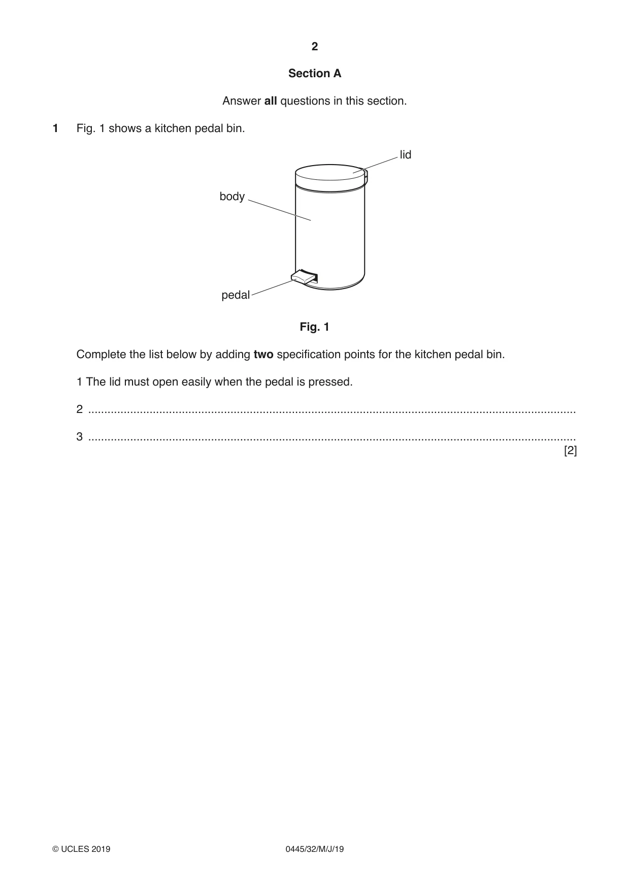
1 Fig. 1 shows a kitchen pedal bin. lid body pedal Fig. 1 Complete the list below by adding two specification points for the kitchen pedal bin. 1 The lid must open easily when the pedal is pressed. 2 ....................................................................................................................................................... 3 ....................................................................................................................................................... [2]
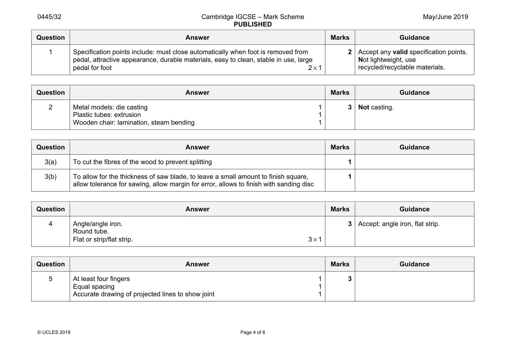
Mark scheme: 1 Specification points include: must close automatically when foot is removed from pedal, attractive appearance, durable materials, easy to clean, stable in use, large pedal for foot 2 × 1 2 Not lightweight, use recycled/recyclable materials.
Q2 · Complete the table by stating the manufacturing process used to make each product
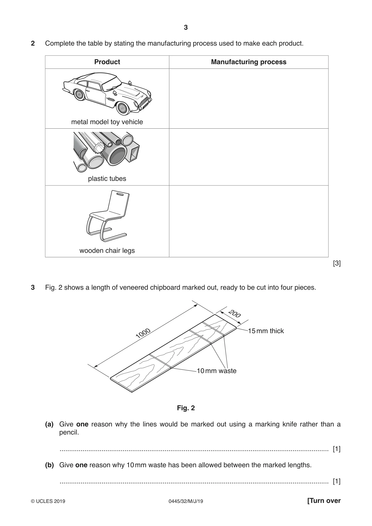
2 Complete the table by stating the manufacturing process used to make each product. Product Manufacturing process metal model toy vehicle plastic tubes wooden chair legs [3]
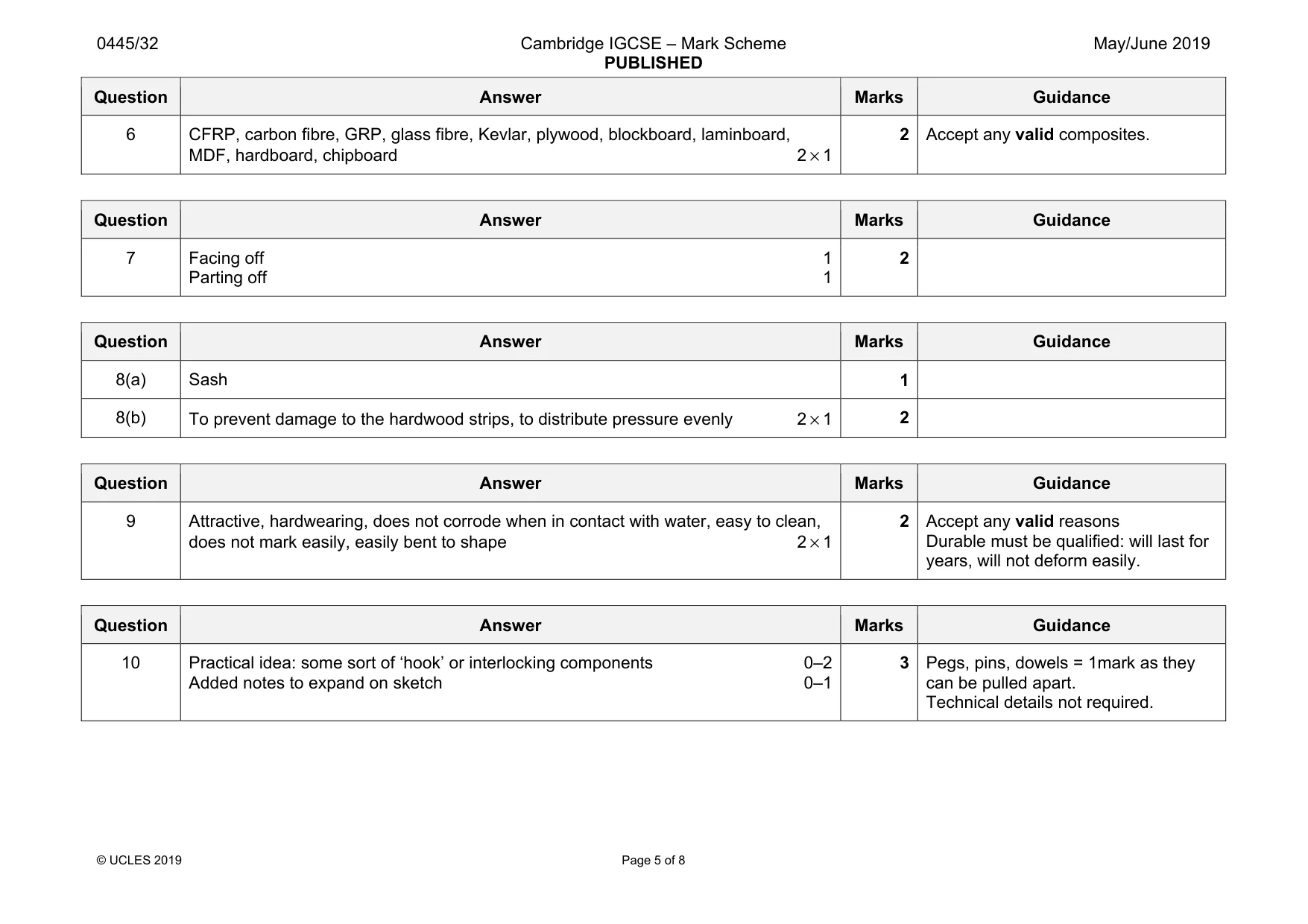
Mark scheme: 2 Metal models: die casting 1 Plastic tubes: extrusion 1 Wooden chair: lamination, steam bending 1 3 Not casting.
Q3 · A length of veneered chipboard marked out, ready to be cut into four pieces
3 Fig. 2 shows a length of veneered chipboard marked out, ready to be cut into four pieces. 200 1000 15 mm thick 10 mm waste Fig. 2 (a) Give one reason why the lines would be marked out using a marking knife rather than a pencil. ............................................................................................................................................. [1] (b) Give one reason why 10 mm waste has been allowed between the marked lengths. ............................................................................................................................................. [1]
Mark scheme: 3(a) To cut the fibres of the wood to prevent splitting 1 3(b) To allow for the thickness of saw blade, to leave a small amount to finish square, allow tolerance for sawing, allow margin for error, allows to finish with sanding disc 1
Q4 · Name the three standard metal sections shown below
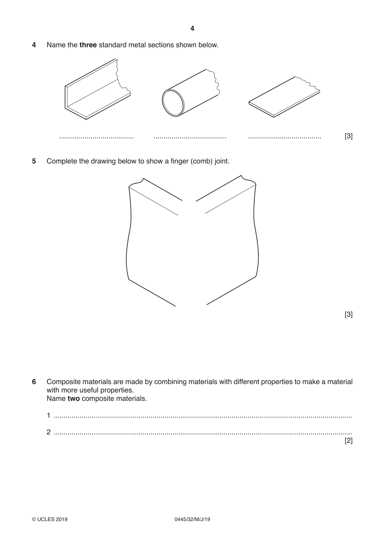
4 Name the three standard metal sections shown below. ...................................... ..................................... ..................................... [3]
Mark scheme: 4 Angle/angle iron. Round tube. Flat or strip/flat strip. 3 × 1 3
Q5 · Complete the drawing below to show a finger (comb) joint
5 Complete the drawing below to show a finger (comb) joint. [3]
Mark scheme: 5 At least four fingers 1 Equal spacing 1 Accurate drawing of projected lines to show joint 1 3
Q6 · Composite materials are made by combining materials with different properties to make a…
6 Composite materials are made by combining materials with different properties to make a material with more useful properties. Name two composite materials. 1 ....................................................................................................................................................... 2 ....................................................................................................................................................... [2]
Mark scheme: 6 CFRP, carbon fibre, GRP, glass fibre, Kevlar, plywood, blockboard, laminboard, MDF, hardboard, chipboard 2 × 1 2
Q7 · The table shows two different centre lathe processes used when turning round metal bar
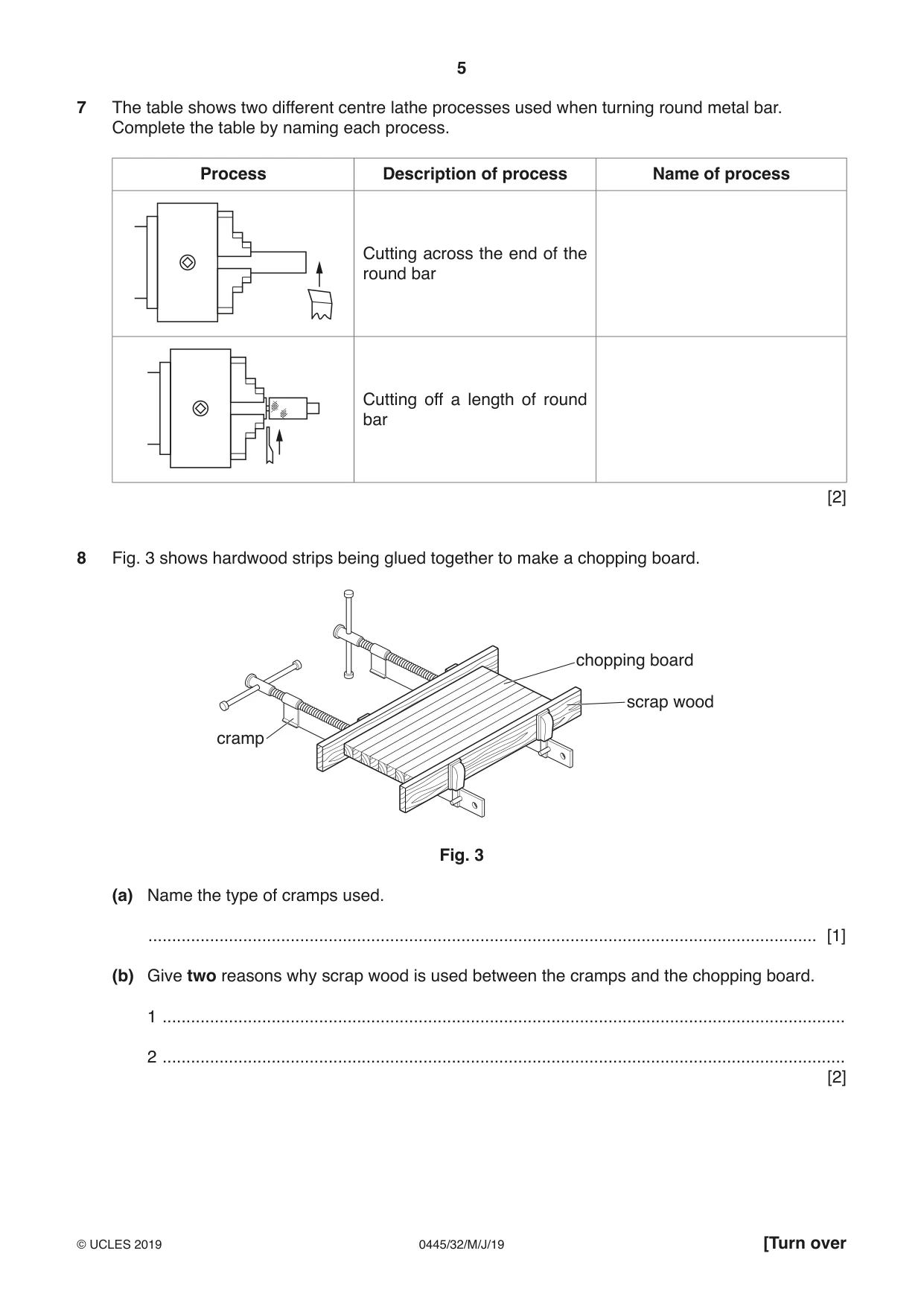
7 The table shows two different centre lathe processes used when turning round metal bar. Complete the table by naming each process. Process Description of process Name of process Cutting across the end of the round bar Cutting off a length of round bar [2]
Mark scheme: 7 Facing off 1 Parting off 1 2
Q8 · Hardwood strips being glued together to make a chopping board
8 Fig. 3 shows hardwood strips being glued together to make a chopping board. chopping board scrap wood cramp Fig. 3 (a) Name the type of cramps used. ............................................................................................................................................. [1] (b) Give two reasons why scrap wood is used between the cramps and the chopping board. 1 ................................................................................................................................................ 2 ................................................................................................................................................ [2]
Mark scheme: 8(a) Sash 1 8(b) To prevent damage to the hardwood strips, to distribute pressure evenly 2 × 1 2
Q9 · A toast rack made from stainless steel
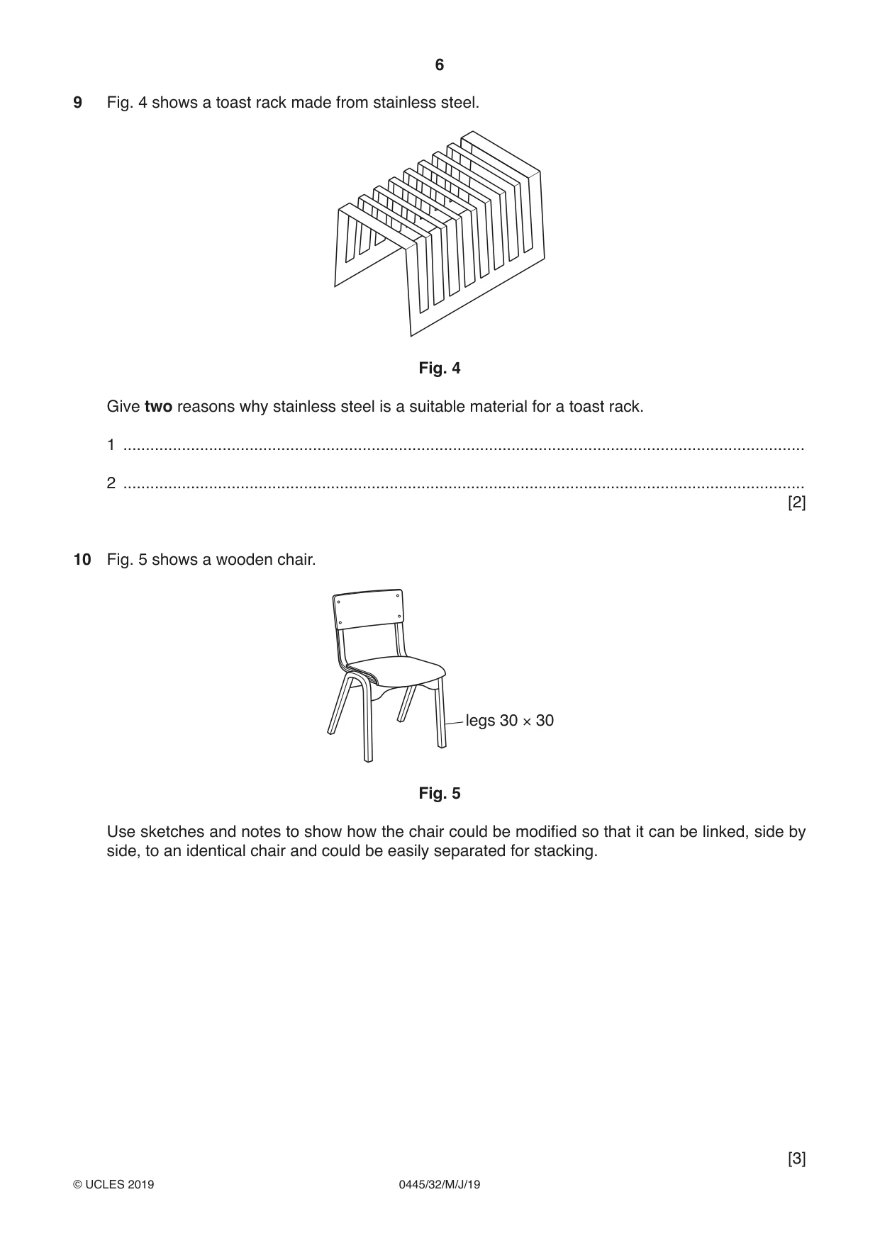
9 Fig. 4 shows a toast rack made from stainless steel. Fig. 4 Give two reasons why stainless steel is a suitable material for a toast rack. 1 ....................................................................................................................................................... 2 ....................................................................................................................................................... [2]
Mark scheme: 9 Attractive, hardwearing, does not corrode when in contact with water, easy to clean, does not mark easily, easily bent to shape 2 × 1 2 Accept any valid reasons Durable must be qualified: will last for years, will not deform easily.
Question 10
10 Fig. 5 shows a wooden chair. legs 30 × 30 Fig. 5 Use sketches and notes to show how the chair could be modified so that it can be linked, side by side, to an identical chair and could be easily separated for stacking. [3]
Mark scheme: 10 Practical idea: some sort of ‘hook’ or interlocking components 0–2 Added notes to expand on sketch 0–1 3 Pegs, pins, dowels = 1mark as they can be pulled apart. Technical details not required.
Q11 · An incomplete design of a child’s novelty clock
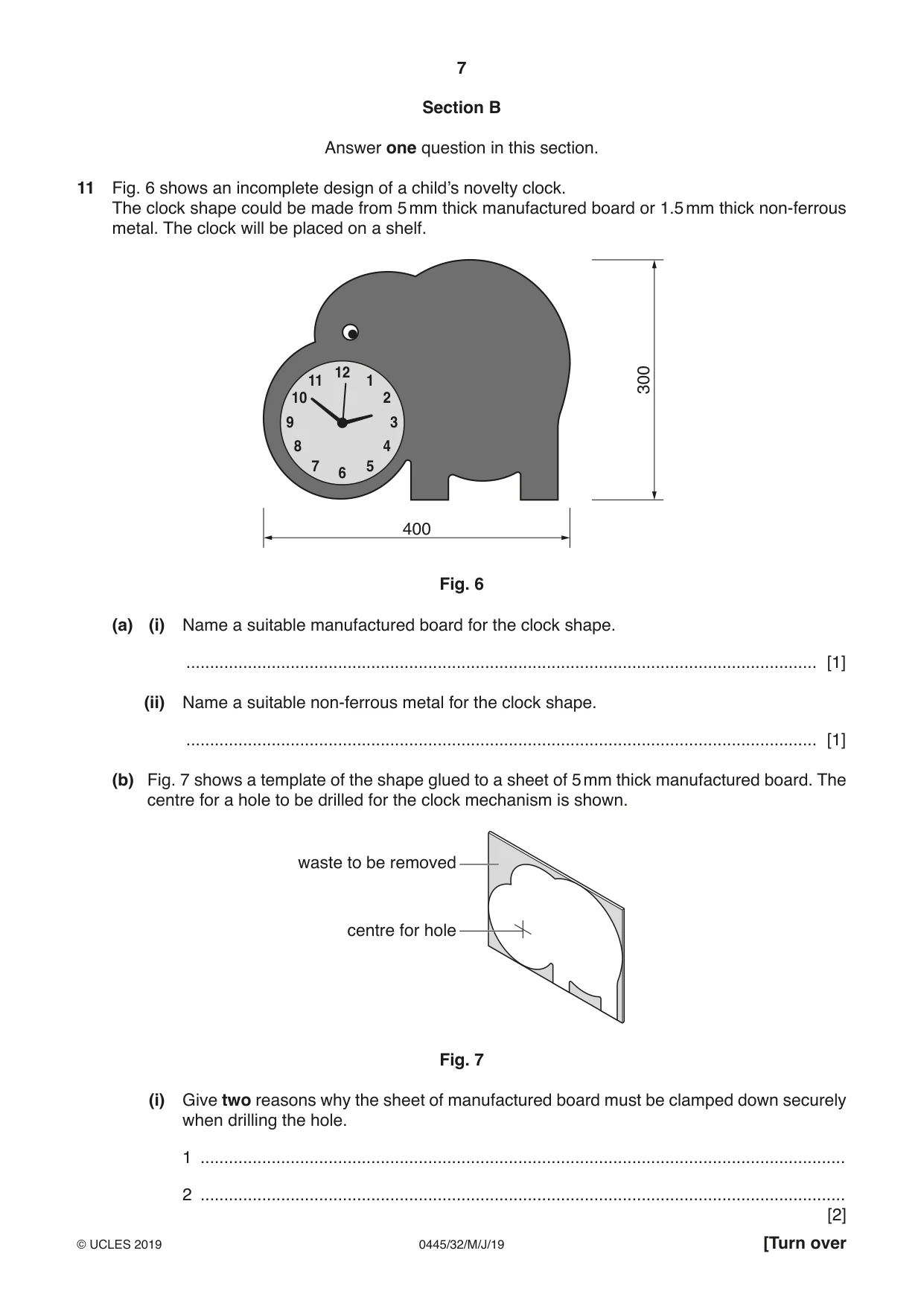
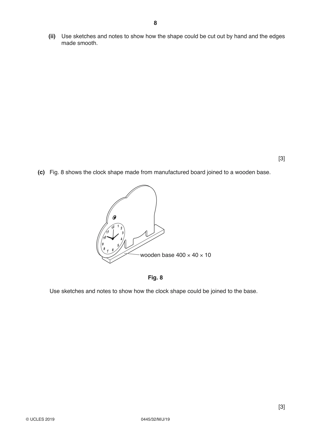
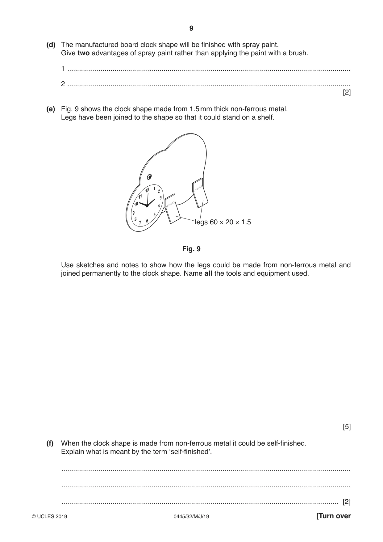
11 Fig. 6 shows an incomplete design of a child’s novelty clock. The clock shape could be made from 5 mm thick manufactured board or 1.5 mm thick non-ferrous metal. The clock will be placed on a shelf. 12 11 1 300 10 2 9 3 8 4 7 5 6 400 Fig. 6 (a) (i) Name a suitable manufactured board for the clock shape. ..................................................................................................................................... [1] (ii) Name a suitable non-ferrous metal for the clock shape. ..................................................................................................................................... [1] (b) Fig. 7 shows a template of the shape glued to a sheet of 5 mm thick manufactured board. The centre for a hole to be drilled for the clock mechanism is shown. waste to be removed centre for hole Fig. 7 (i) Give two reasons why the sheet of manufactured board must be clamped down securely when drilling the hole. 1 ........................................................................................................................................ 2 ........................................................................................................................................ [2] (ii) Use sketches and notes to show how the shape could be cut out by hand and the edges made smooth. [3] (c) Fig. 8 shows the clock shape made from manufactured board joined to a wooden base. 12 1 2 11 3 10 4 9 5 8 7 6 wooden base 400 × 40 × 10 Fig. 8 Use sketches and notes to show how the clock shape could be joined to the base. [3] (d) The manufactured board clock shape will be finished with spray paint. Give two advantages of spray paint rather than applying the paint with a brush. 1 ................................................................................................................................................ 2 ................................................................................................................................................ [2] (e) Fig. 9 shows the clock shape made from 1.5 mm thick non-ferrous metal. Legs have been joined to the shape so that it could stand on a shelf. 12 1 2 11 3 10 4 9 5 8 7 6 legs 60 × 20 × 1.5 Fig. 9 Use sketches and notes to show how the legs could be made from non-ferrous metal and joined permanently to the clock shape. Name all the tools and equipment used. [5] (f) When the clock shape is made from non-ferrous metal it could be self-finished. Explain what is meant by the term ‘self-finished’. ................................................................................................................................................... ................................................................................................................................................... ............................................................................................................................................. [2] (g) Describe in detail how CAD/CAM could be used to produce the numbers 1 to 12 on the 5 mm thick manufactured board clock face. ................................................................................................................................................... ................................................................................................................................................... ................................................................................................................................................... ................................................................................................................................................... ................................................................................................................................................... ............................................................................................................................................. [4] (h) State two ways, other than shape and colour, by which designers make products used by young children appealing and exciting. 1 ................................................................................................................................................ 2 ................................................................................................................................................ [2]
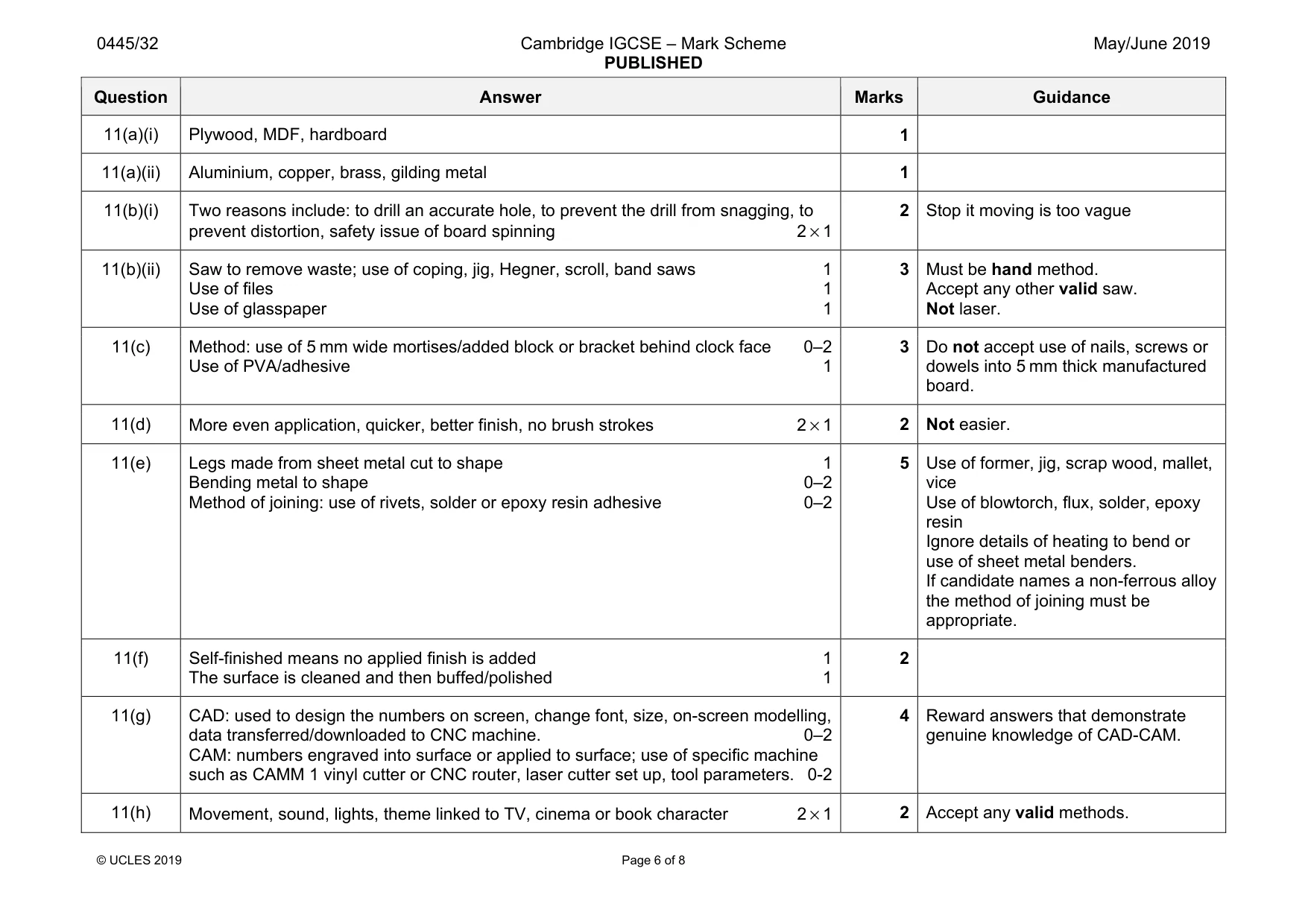
Mark scheme: 11(a)(i) Plywood, MDF, hardboard 1 11(a)(ii) Aluminium, copper, brass, gilding metal 1 11(b)(i) Two reasons include: to drill an accurate hole, to prevent the drill from snagging, to prevent distortion, safety issue of board spinning 2 × 1 2 Stop it moving is too vague 11(b)(ii) Saw to remove waste; use of coping, jig, Hegner, scroll, band saws 1 Use of files 1 Use of glasspaper 1 3 Must be hand method. Accept any other valid saw. Not laser. 11(c) Method: use of 5 mm wide mortises/added block or bracket behind clock face 0–2 Use of PVA/adhesive 1 3 Do not accept use of nails, screws or dowels into 5 mm thick manufactured board. 11(d) More even application, quicker, better finish, no brush strokes 2 × 1 2 Not easier. 11(e) Legs made from sheet metal cut to shape 1 Bending metal to shape 0–2 Method of joining: use of rivets, solder or epoxy resin adhesive 0–2 5 Use of former, jig, scrap wood, mallet, vice Use of blowtorch, flux, solder, epoxy resin Ignore details of heating to bend or use of sheet metal benders. If candidate names a non-ferrous alloy the method of joining must be appropriate. 11(f) Self-finished means no applied finish is added 1 The surface is cleaned and then buffed/polished 1 2 11(g) CAD: used to design the numbers on screen, change font, size, on-screen modelling, data transferred/downloaded to CNC machine. 0–2 CAM: numbers engraved into surface or applied to surface; use of specific machine such as CAMM 1 vinyl cutter or CNC router, laser cutter set up, tool parameters. 0-2 4 Reward answers that demonstrate genuine knowledge of CAD-CAM. 11(h) Movement, sound, lights, theme linked to TV, cinema or book character 2 × 1 2 Accept any valid methods.
Q12 · Views of a storage unit designed to hold a tablet, mobile phone and remote control
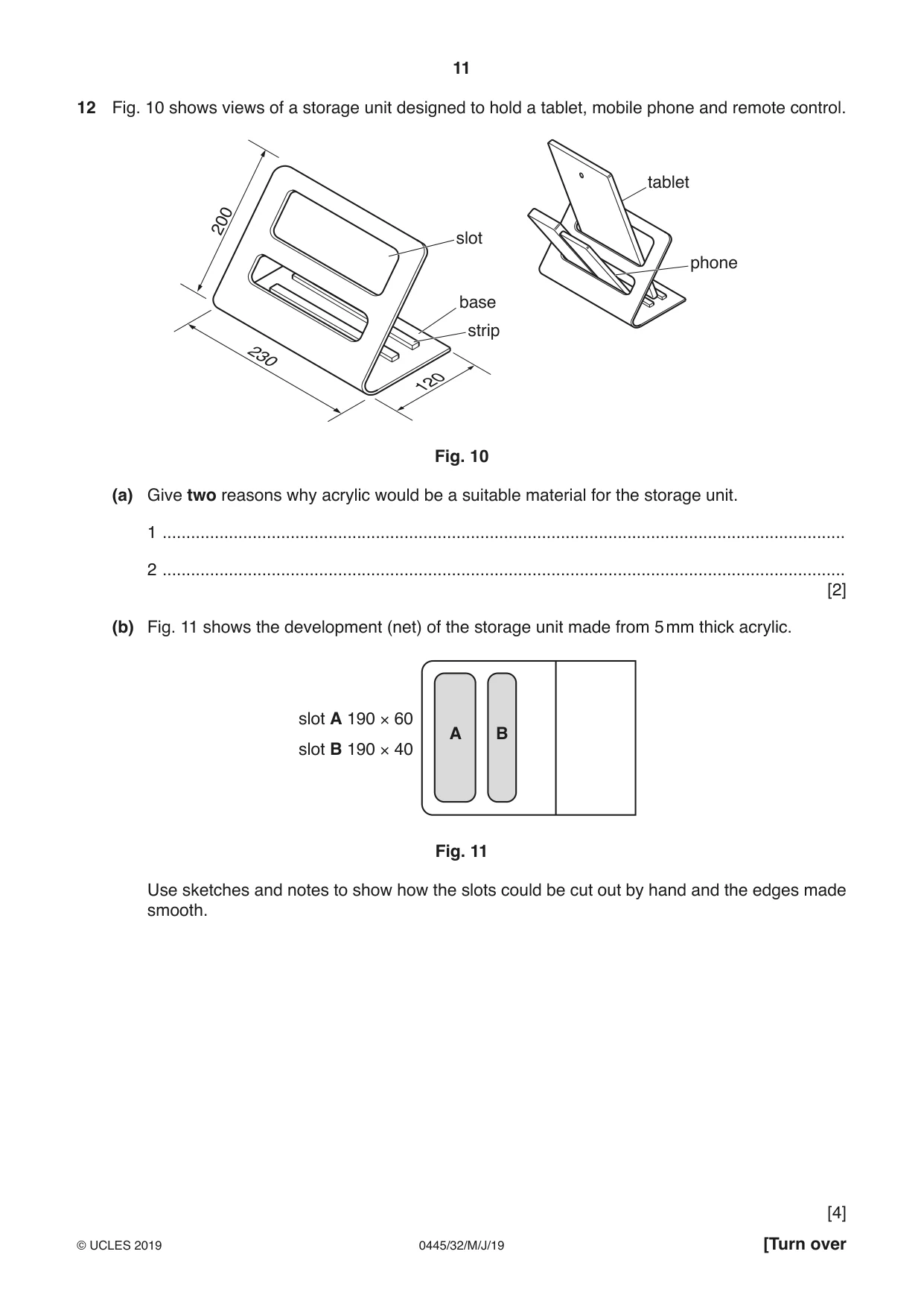
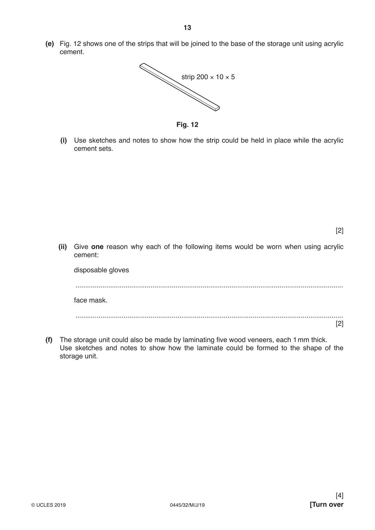
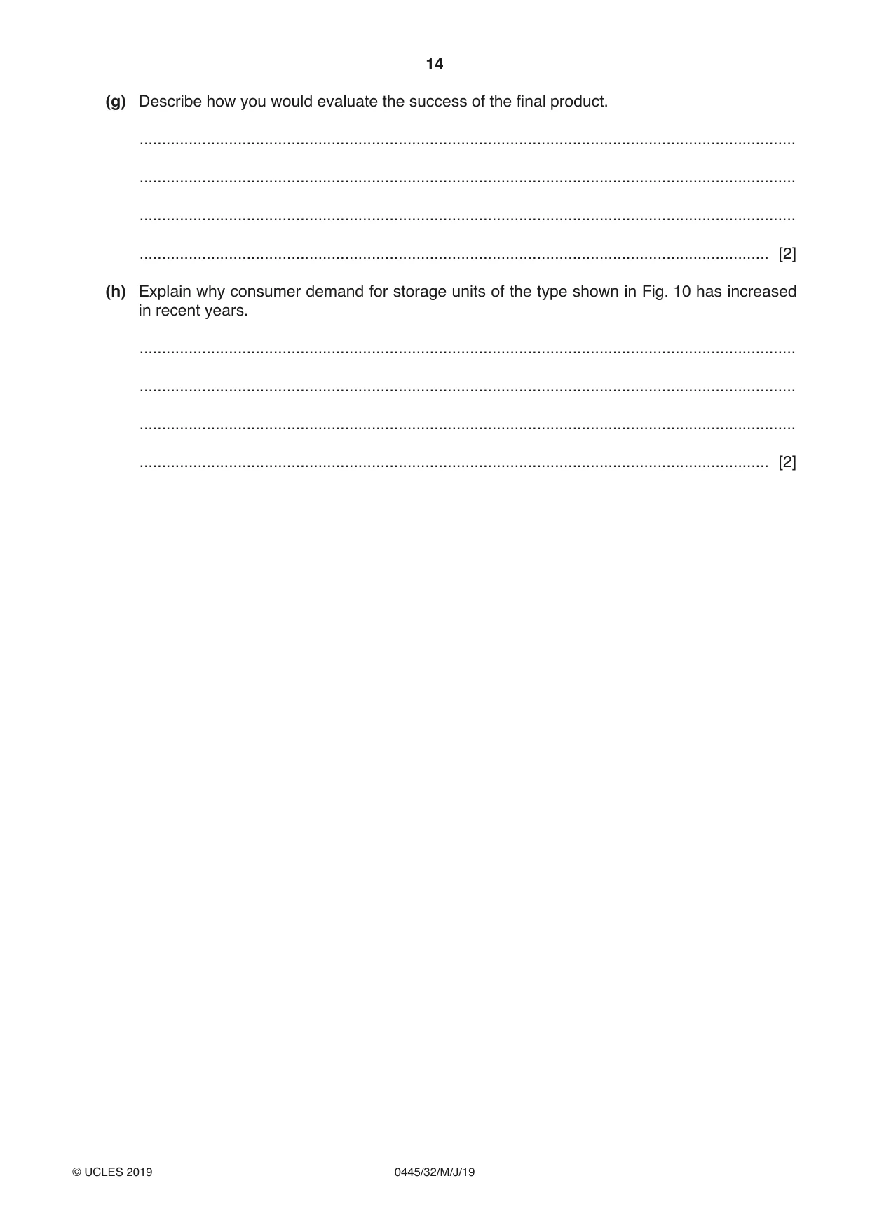
12 Fig. 10 shows views of a storage unit designed to hold a tablet, mobile phone and remote control. tablet 200 slot phone base strip 230 120 Fig. 10 (a) Give two reasons why acrylic would be a suitable material for the storage unit. 1 ................................................................................................................................................ 2 ................................................................................................................................................ [2] (b) Fig. 11 shows the development (net) of the storage unit made from 5 mm thick acrylic. slot A 190 × 60 A B slot B 190 × 40 Fig. 11 Use sketches and notes to show how the slots could be cut out by hand and the edges made smooth. [4] (c) The development (net) and slots could be cut out using a CNC machine. Describe the stages involved when using a CNC machine to cut out the development (net) and slots. ................................................................................................................................................... ................................................................................................................................................... ................................................................................................................................................... ................................................................................................................................................... ................................................................................................................................................... ............................................................................................................................................. [4] (d) Use sketches and notes to show how the acrylic development (net) could be bent to shape. [3] (e) Fig. 12 shows one of the strips that will be joined to the base of the storage unit using acrylic cement. strip 200 × 10 × 5 Fig. 12 (i) Use sketches and notes to show how the strip could be held in place while the acrylic cement sets. [2] (ii) Give one reason why each of the following items would be worn when using acrylic cement: disposable gloves ........................................................................................................................................... face mask. ........................................................................................................................................... [2] (f) The storage unit could also be made by laminating five wood veneers, each 1 mm thick. Use sketches and notes to show how the laminate could be formed to the shape of the storage unit. (g) Describe how you would evaluate the success of the final product. ................................................................................................................................................... ................................................................................................................................................... ................................................................................................................................................... ............................................................................................................................................. [2] (h) Explain why consumer demand for storage units of the type shown in Fig. 10 has increased in recent years. ................................................................................................................................................... ................................................................................................................................................... ................................................................................................................................................... ............................................................................................................................................. [2]
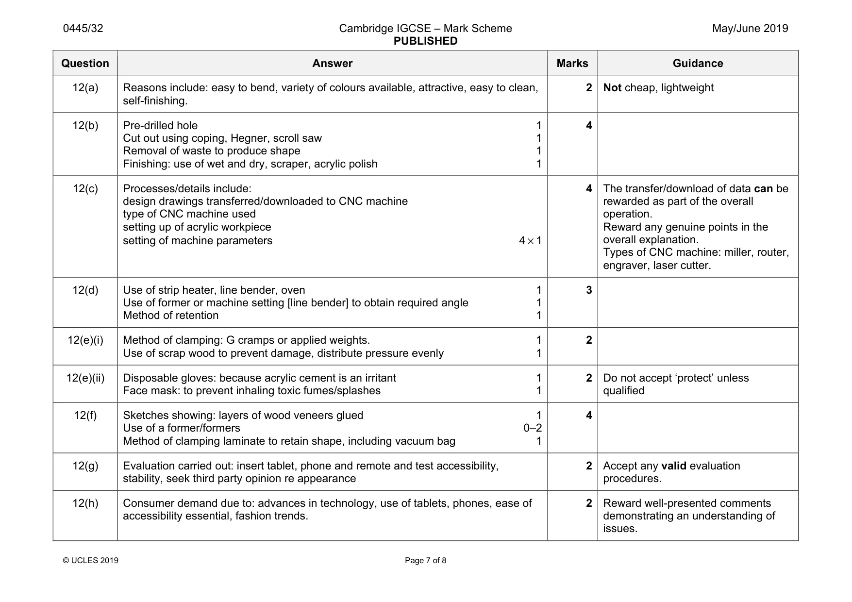
Mark scheme: 12(a) Reasons include: easy to bend, variety of colours available, attractive, easy to clean, self-finishing. 2 12(b) Pre-drilled hole 1 Cut out using coping, Hegner, scroll saw 1 Removal of waste to produce shape 1 Finishing: use of wet and dry, scraper, acrylic polish 1 4 12(c) Processes/details include: design drawings transferred/downloaded to CNC machine type of CNC machine used setting up of acrylic workpiece setting of machine parameters 4 × 1 4 The transfer/download of data can be rewarded as part of the overall operation. Reward any genuine points in the overall explanation. Types of CNC machine: miller, router, engraver, laser cutter. 12(d) Use of strip heater, line bender, oven 1 Use of former or machine setting [line bender] to obtain required angle 1 Method of retention 1 3 12(e)(i) Method of clamping: G cramps or applied weights. 1 Use of scrap wood to prevent damage, distribute pressure evenly 1 2 12(e)(ii) Disposable gloves: because acrylic cement is an irritant 1 Face mask: to prevent inhaling toxic fumes/splashes 1 2 Do not accept ‘protect’ unless qualified 12(f) Sketches showing: layers of wood veneers glued 1 Use of a former/formers 0–2 Method of clamping laminate to retain shape, including vacuum bag 1 4 12(g) Evaluation carried out: insert tablet, phone and remote and test accessibility, stability, seek third party opinion re appearance 2 Accept any valid evaluation procedures. 12(h) Consumer demand due to: advances in technology, use of tablets, phones, ease of accessibility essential, fashion trends. 2 Reward well-presented comments demonstrating an understanding of issues.
Q13 · A child’s ride-on toy made mainly from wood
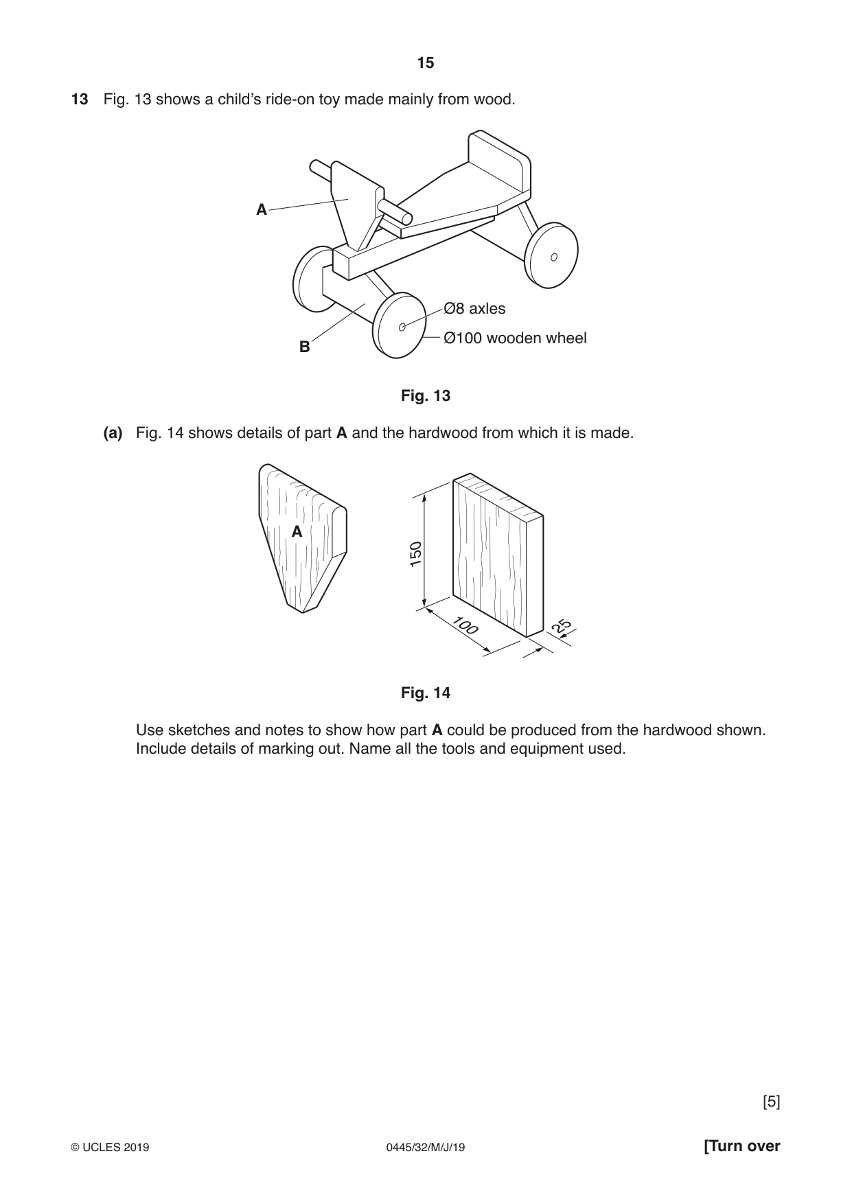
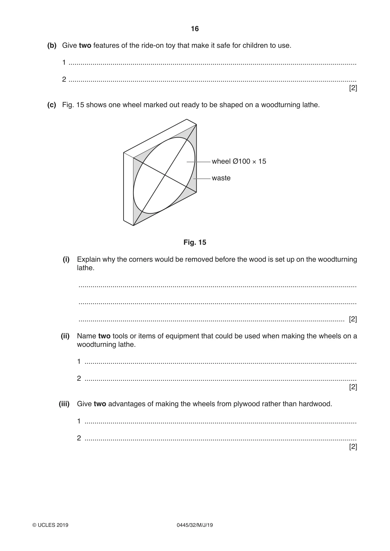
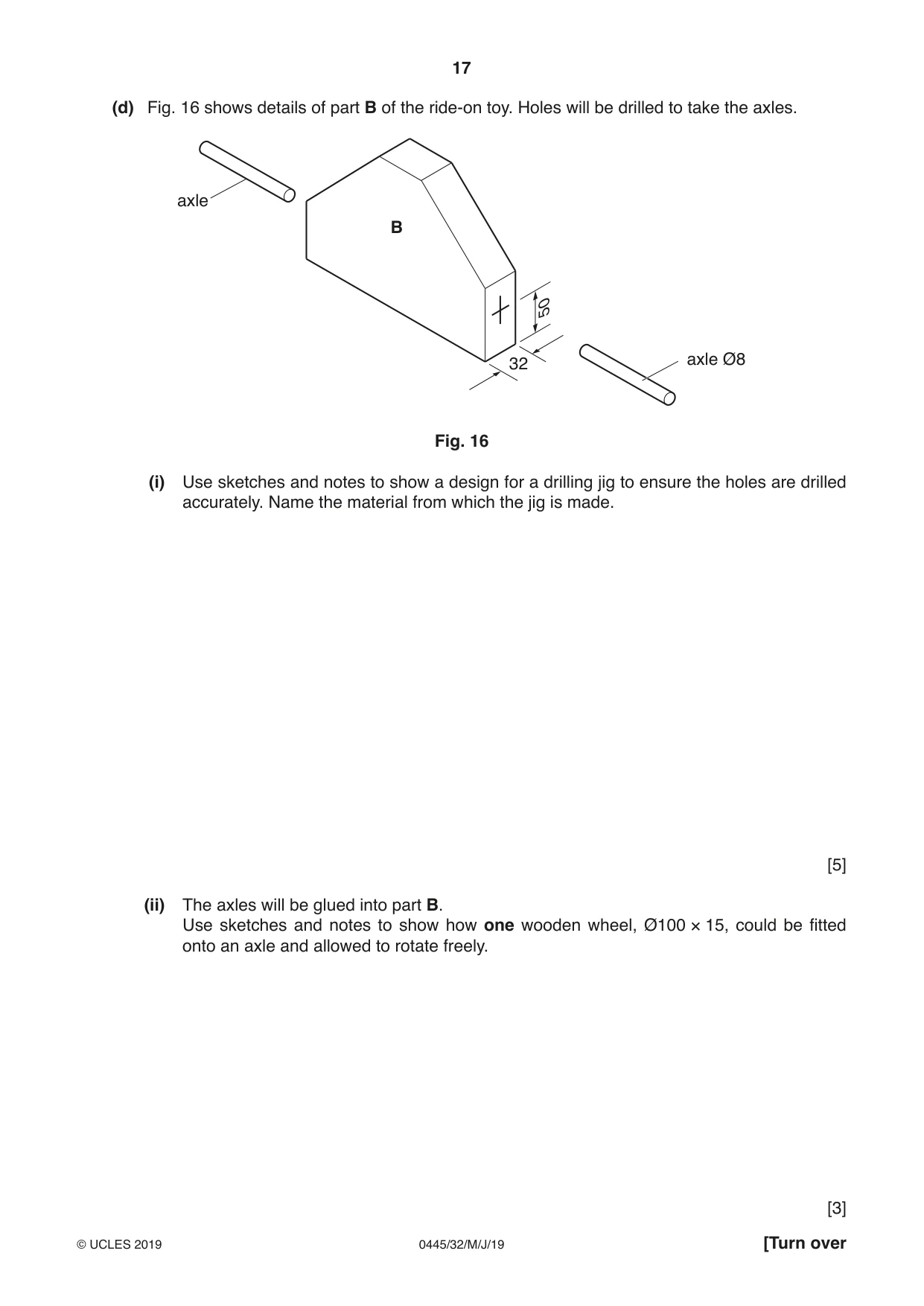
13 Fig. 13 shows a child’s ride-on toy made mainly from wood. A Ø8 axles Ø100 wooden wheel B Fig. 13 (a) Fig. 14 shows details of part A and the hardwood from which it is made. A 150 100 25 Fig. 14 Use sketches and notes to show how part A could be produced from the hardwood shown. Include details of marking out. Name all the tools and equipment used. [5] (b) Give two features of the ride-on toy that make it safe for children to use. 1 ................................................................................................................................................ 2 ................................................................................................................................................ [2] (c) Fig. 15 shows one wheel marked out ready to be shaped on a woodturning lathe. wheel Ø100 × 15 waste Fig. 15 (i) Explain why the corners would be removed before the wood is set up on the woodturning lathe. ........................................................................................................................................... ........................................................................................................................................... ..................................................................................................................................... [2] (ii) Name two tools or items of equipment that could be used when making the wheels on a woodturning lathe. 1 ........................................................................................................................................ 2 ........................................................................................................................................ [2] (iii) Give two advantages of making the wheels from plywood rather than hardwood. 1 ........................................................................................................................................ 2 ........................................................................................................................................ [2] (d) Fig. 16 shows details of part B of the ride-on toy. Holes will be drilled to take the axles. axle B 50 32 axle Ø8 Fig. 16 (i) Use sketches and notes to show a design for a drilling jig to ensure the holes are drilled accurately. Name the material from which the jig is made. [5] (ii) The axles will be glued into part B. Use sketches and notes to show how one wooden wheel, Ø100 × 15, could be fitted onto an axle and allowed to rotate freely. [3]
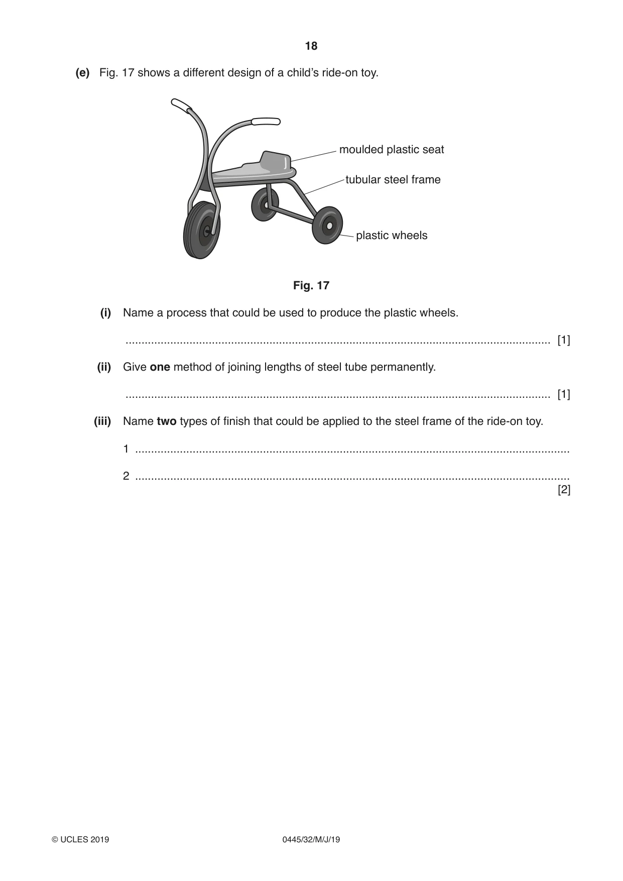
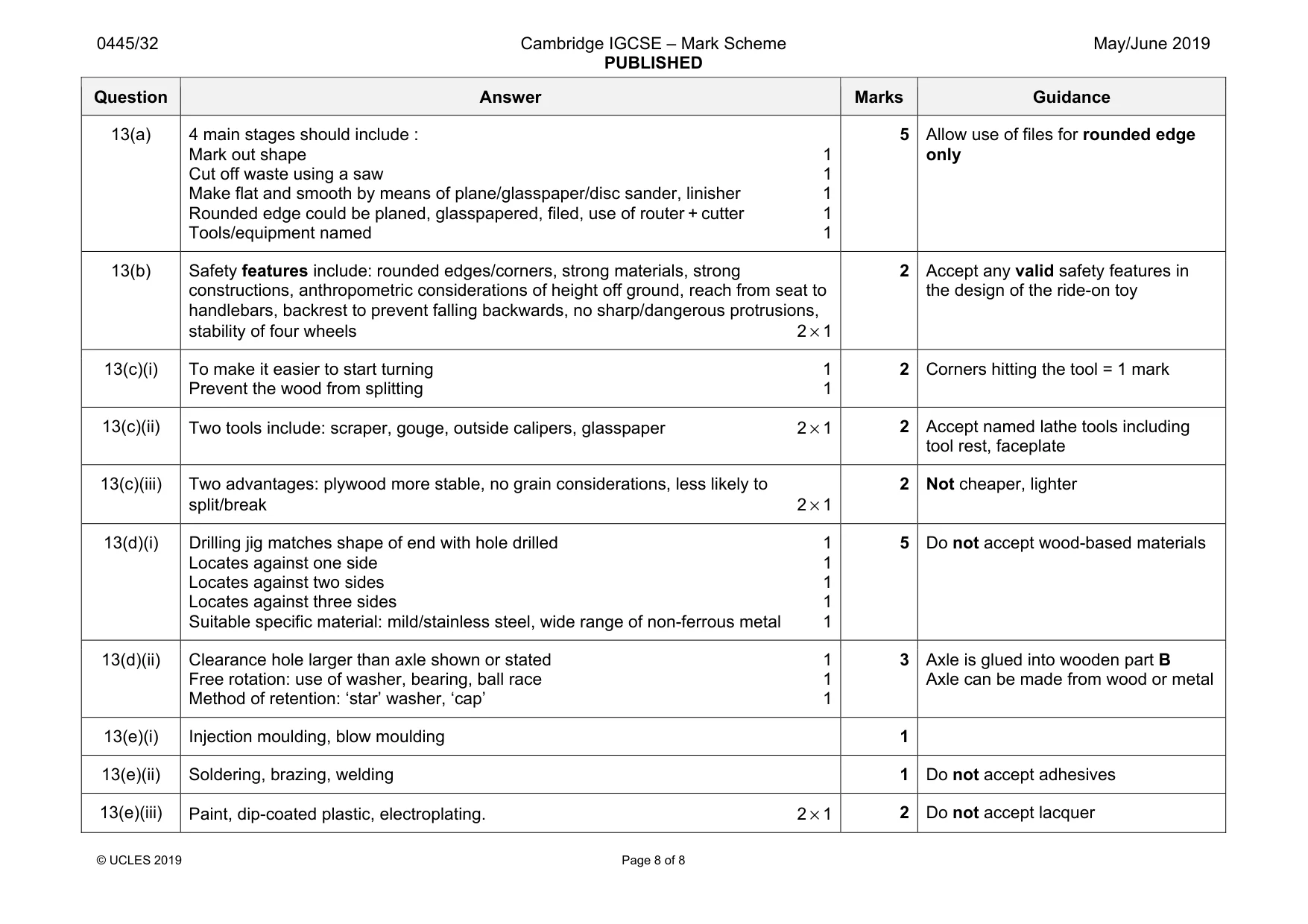
Mark scheme: 13(a) 4 main stages should include : Mark out shape 1 Cut off waste using a saw 1 Make flat and smooth by means of plane/glasspaper/disc sander, linisher 1 Rounded edge could be planed, glasspapered, filed, use of router + cutter 1 Tools/equipment named 1 5 only 13(b) Safety features include: rounded edges/corners, strong materials, strong constructions, anthropometric considerations of height off ground, reach from seat to handlebars, backrest to prevent falling backwards, no sharp/dangerous protrusions, stability of four wheels 2 × 1 2 Accept any valid safety features in the design of the ride-on toy 13(c)(i) To make it easier to start turning 1 Prevent the wood from splitting 1 2 Corners hitting the tool = 1 mark 13(c)(ii) Two tools include: scraper, gouge, outside calipers, glasspaper 2 × 1 2 Accept named lathe tools including tool rest, faceplate 13(c)(iii) Two advantages: plywood more stable, no grain considerations, less likely to split/break 2 × 1 2 Not cheaper, lighter 13(d)(i) Drilling jig matches shape of end with hole drilled 1 Locates against one side 1 Locates against two sides 1 Locates against three sides 1 Suitable specific material: mild/stainless steel, wide range of non-ferrous metal 1 5 Do not accept wood-based materials 13(d)(ii) Clearance hole larger than axle shown or stated 1 Free rotation: use of washer, bearing, ball race 1 Method of retention: ‘star’ washer, ‘cap’ 1 3 Axle is glued into wooden part B Axle can be made from wood or metal 13(e)(i) Injection moulding, blow moulding 1 13(e)(ii) Soldering, brazing, welding 1 Do not accept adhesives 13(e)(iii) Paint, dip-coated plastic, electroplating. 2 × 1 2 Do not accept lacquer
What was in this paper
The subtopics covered by these 13 questions, and how many questions each got. Open one in a new tab to see every Cambridge question on it.
What you needed in this session
Cambridge’s own grade thresholds for 2019 May/June, Paper 3 · Variant 2. A higher threshold means an easier paper — the bar moves with how the cohort did.