Cambridge IGCSE Design and Technology 0445 — 2019 May/June Paper 3 · Variant 1
0445/31/M/J/19 · 13 questions · 50 marks · ≈56 min
The question paper and its mark scheme, free to read here and free to download. This is Cambridge’s own paper, exactly as it was sat.
Question paper20 pages



Mark scheme9 pages
Answers below. Sit the paper first if you are practising.
Questions as text
Q1 · Two signs used in a workshop are shown below
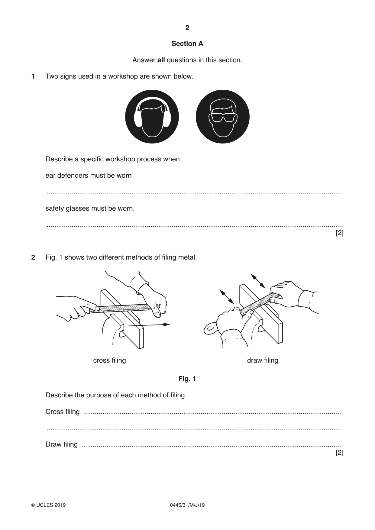
1 Two signs used in a workshop are shown below. Describe a specific workshop process when: ear defenders must be worn .......................................................................................................................................................... safety glasses must be worn. .......................................................................................................................................................... [2]
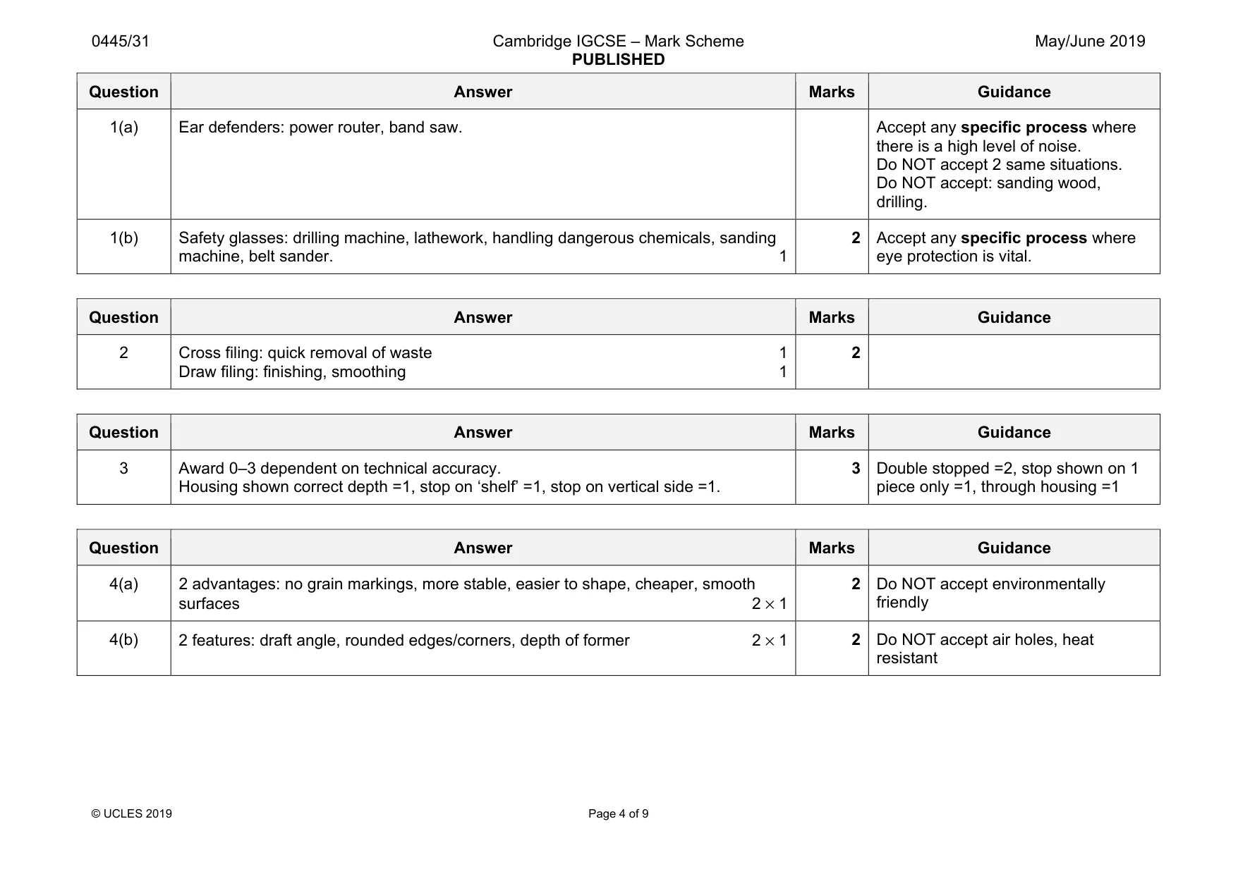
Mark scheme: 1(b) Safety glasses: drilling machine, lathework, handling dangerous chemicals, sanding machine, belt sander. 1 2 Accept any specific process where eye protection is vital.
Q2 · Two different methods of filing metal
2 Fig. 1 shows two different methods of filing metal. cross filing draw filing Fig. 1 Describe the purpose of each method of filing. Cross filing ....................................................................................................................................... .......................................................................................................................................................... Draw filing ........................................................................................................................................ [2]
Mark scheme: 2 Cross filing: quick removal of waste 1 Draw filing: finishing, smoothing 1 2
Q3 · Complete the drawing below to show an exploded view of a stopped housing joint
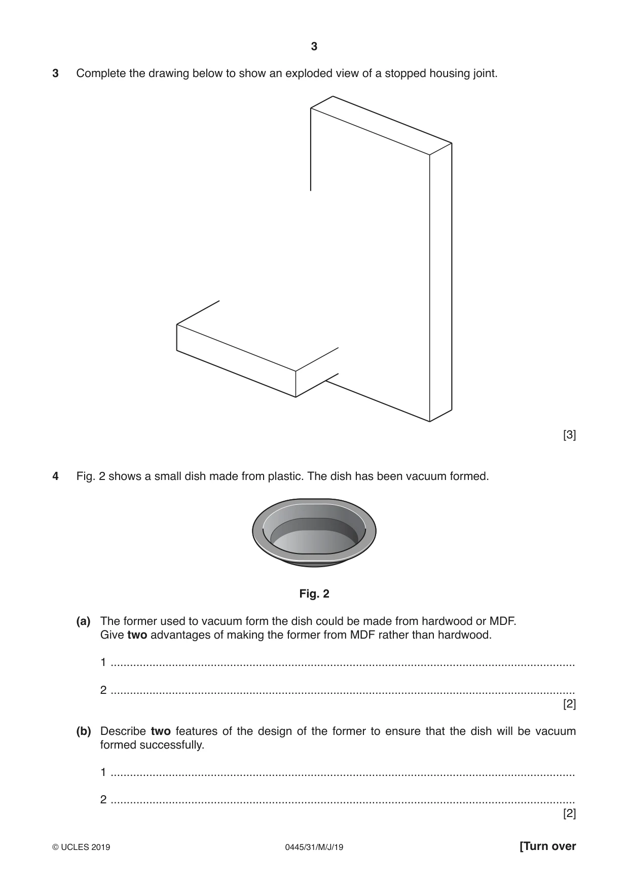
3 Complete the drawing below to show an exploded view of a stopped housing joint. [3]
Mark scheme: 3 Award 0–3 dependent on technical accuracy. Housing shown correct depth =1, stop on ‘shelf’ =1, stop on vertical side =1. 3 piece only =1, through housing =1
Q4 · A small dish made from plastic
4 Fig. 2 shows a small dish made from plastic. The dish has been vacuum formed. Fig. 2 (a) The former used to vacuum form the dish could be made from hardwood or MDF. Give two advantages of making the former from MDF rather than hardwood. 1 ................................................................................................................................................ 2 ................................................................................................................................................ [2] (b) Describe two features of the design of the former to ensure that the dish will be vacuum formed successfully. 1 ................................................................................................................................................ 2 ................................................................................................................................................ [2]
Mark scheme: 4(a) 2 advantages: no grain markings, more stable, easier to shape, cheaper, smooth surfaces 2 × 1 2 Do NOT accept environmentally friendly 4(b) 2 features: draft angle, rounded edges/corners, depth of former 2 × 1 2 Do NOT accept air holes, heat resistant
Question 5
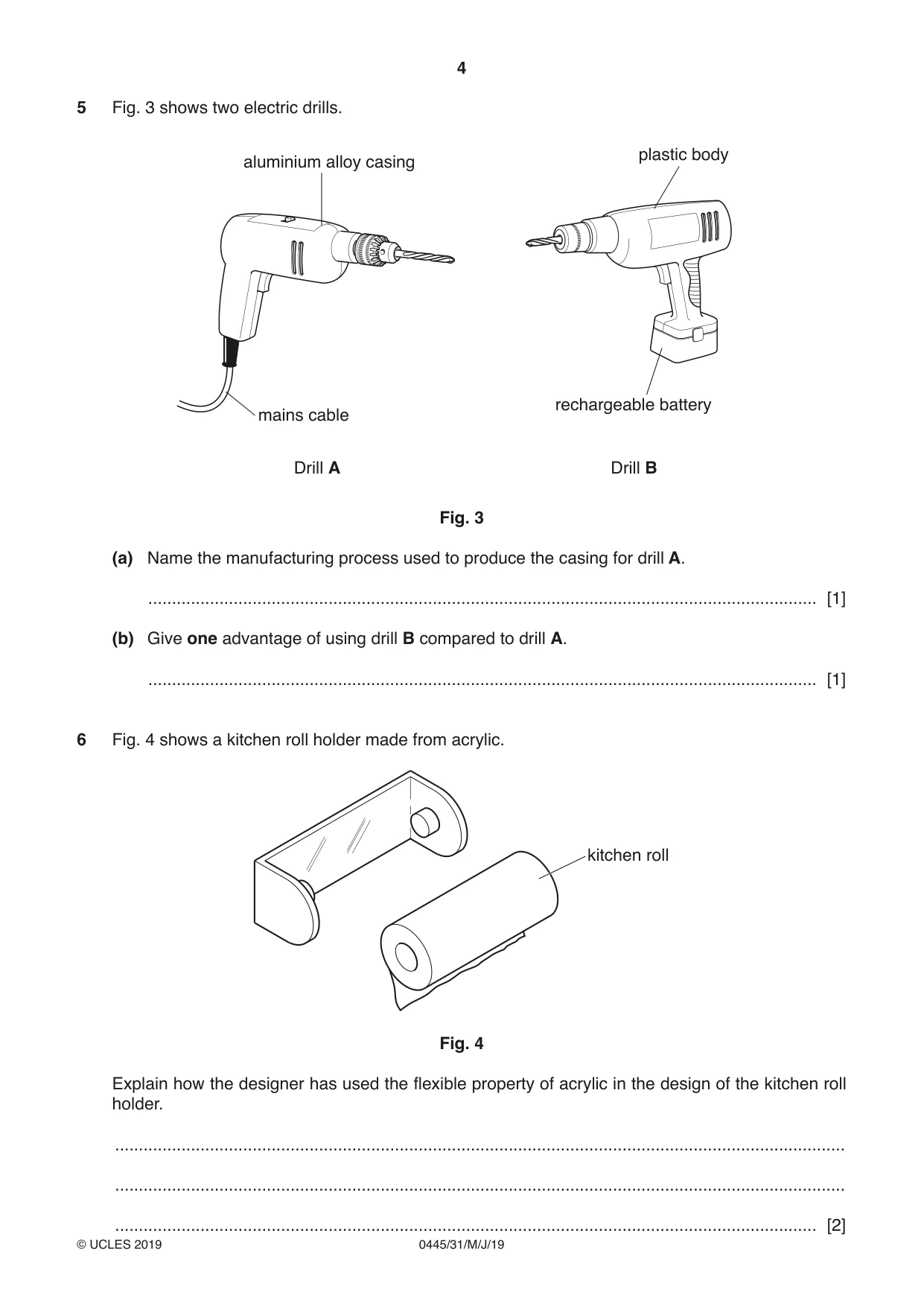
5 Fig. 3 shows two electric drills. plastic body aluminium alloy casing rechargeable battery mains cable Drill A Drill B Fig. 3 (a) Name the manufacturing process used to produce the casing for drill A. ............................................................................................................................................. [1] (b) Give one advantage of using drill B compared to drill A. ............................................................................................................................................. [1]
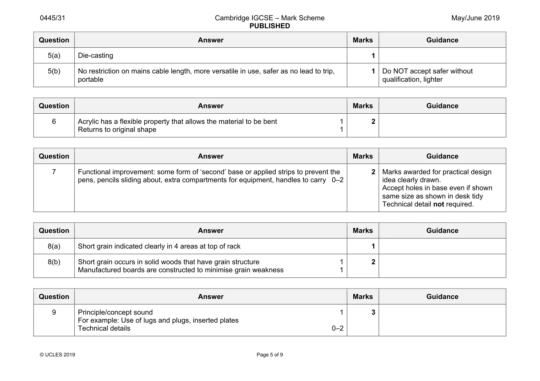
Mark scheme: 5(a) Die-casting 1 5(b) No restriction on mains cable length, more versatile in use, safer as no lead to trip, portable 1 Do NOT accept safer without qualification, lighter
Q6 · A kitchen roll holder made from acrylic
6 Fig. 4 shows a kitchen roll holder made from acrylic. kitchen roll Fig. 4 Explain how the designer has used the flexible property of acrylic in the design of the kitchen roll holder. .......................................................................................................................................................... ..........................................................................................................................................................
Mark scheme: 6 Acrylic has a flexible property that allows the material to be bent 1 Returns to original shape 1 2
Q7 · A basic design for a desk tidy made in a school workshop
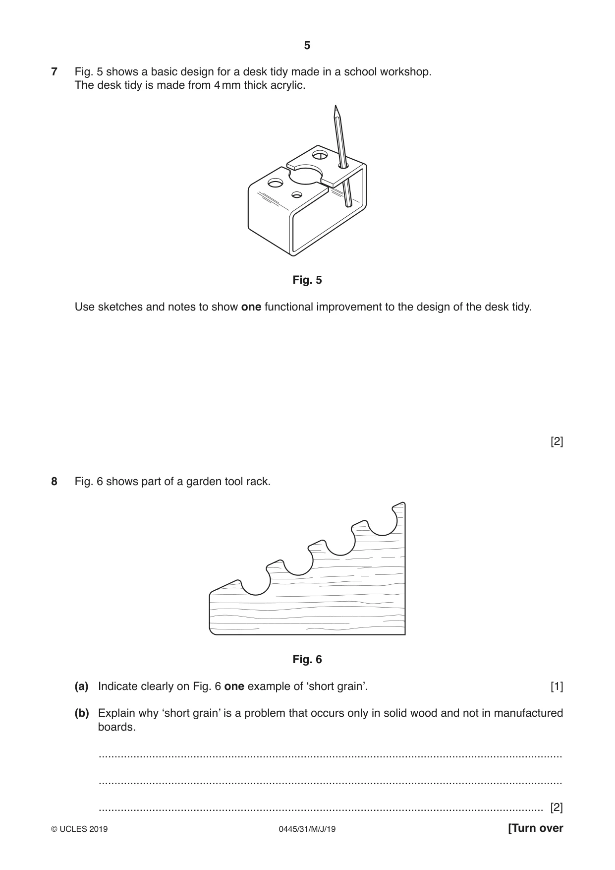
7 Fig. 5 shows a basic design for a desk tidy made in a school workshop. The desk tidy is made from 4 mm thick acrylic. Fig. 5 Use sketches and notes to show one functional improvement to the design of the desk tidy. [2]
Mark scheme: 7 Functional improvement: some form of ‘second’ base or applied strips to prevent the pens, pencils sliding about, extra compartments for equipment, handles to carry 0–2 2 Marks awarded for practical design idea clearly drawn. Accept holes in base even if shown same size as shown in desk tidy Technical detail not required.
Q8 · Part of a garden tool rack
8 Fig. 6 shows part of a garden tool rack. Fig. 6 (a) Indicate clearly on Fig. 6 one example of ‘short grain’. [1] (b) Explain why ‘short grain’ is a problem that occurs only in solid wood and not in manufactured boards. ................................................................................................................................................... ................................................................................................................................................... ............................................................................................................................................. [2]
Mark scheme: 8(a) Short grain indicated clearly in 4 areas at top of rack 1 8(b) Short grain occurs in solid woods that have grain structure 1 Manufactured boards are constructed to minimise grain weakness 1 2
Q9 · A round tube that will be joined to a metal strip made from mild steel
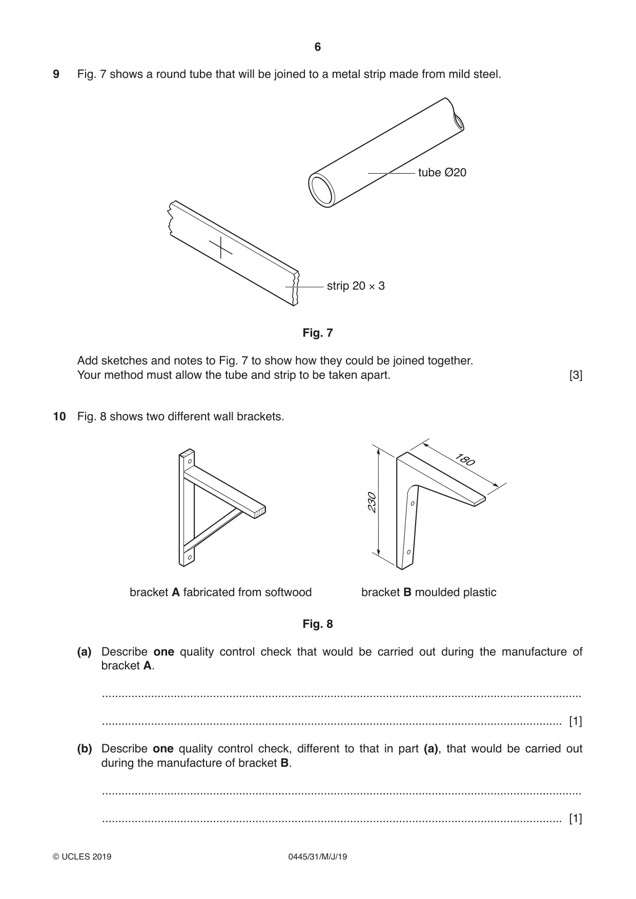
9 Fig. 7 shows a round tube that will be joined to a metal strip made from mild steel. tube Ø20 strip 20 × 3 Fig. 7 Add sketches and notes to Fig. 7 to show how they could be joined together. Your method must allow the tube and strip to be taken apart. [3]
Mark scheme: 9 Principle/concept sound 1 For example: Use of lugs and plugs, inserted plates Technical details 0–2 3
Q10 · Two different wall brackets
10 Fig. 8 shows two different wall brackets. 180 230 bracket A fabricated from softwood bracket B moulded plastic Fig. 8 (a) Describe one quality control check that would be carried out during the manufacture of bracket A. ................................................................................................................................................... ............................................................................................................................................. [1] (b) Describe one quality control check, different to that in part (a), that would be carried out during the manufacture of bracket B. ................................................................................................................................................... ............................................................................................................................................. [1]
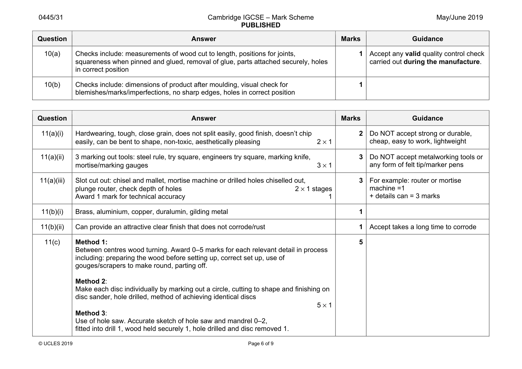
Mark scheme: 10(a) Checks include: measurements of wood cut to length, positions for joints, squareness when pinned and glued, removal of glue, parts attached securely, holes in correct position 1 carried out during the manufacture. 10(b) Checks include: dimensions of product after moulding, visual check for blemishes/marks/imperfections, no sharp edges, holes in correct position 1
Q11 · Views of a child’s counting toy
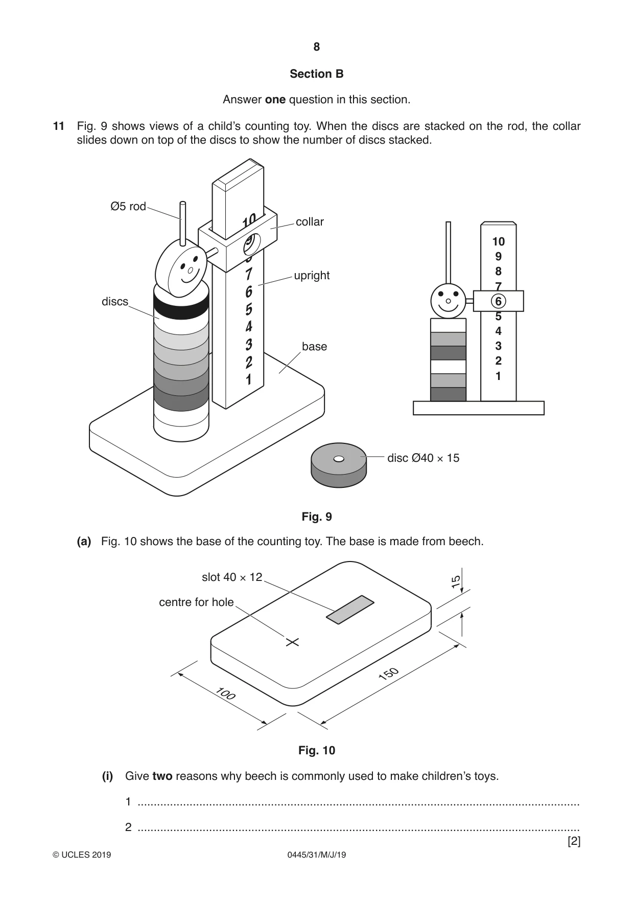
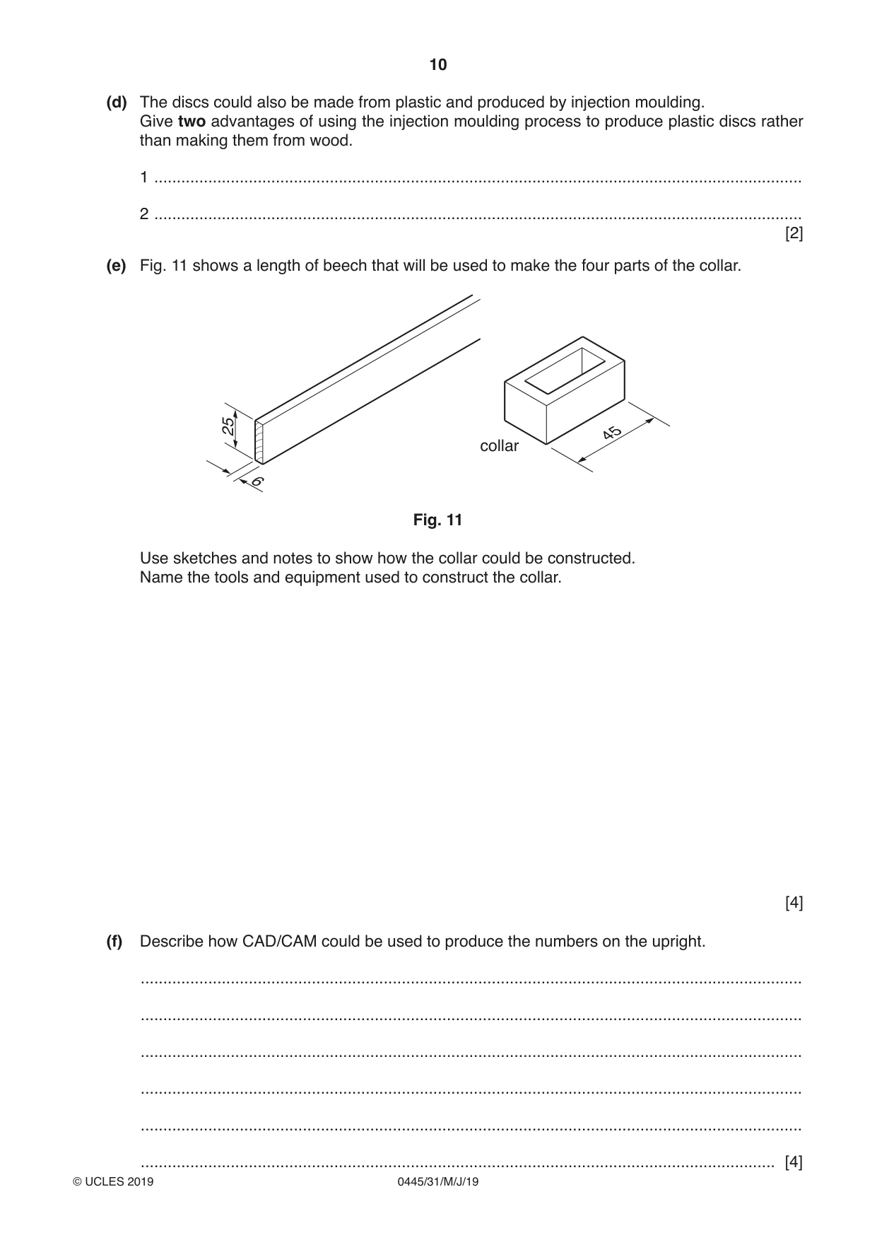
11 Fig. 9 shows views of a child’s counting toy. When the discs are stacked on the rod, the collar slides down on top of the discs to show the number of discs stacked. Ø5 rod collar 10 9 8 upright 7 discs 6 5 4 base 3 2 1 disc Ø40 × 15 Fig. 9 (a) Fig. 10 shows the base of the counting toy. The base is made from beech. slot 40 × 12 15 centre for hole 150 100 Fig. 10 (i) Give two reasons why beech is commonly used to make children’s toys. 1 ........................................................................................................................................ 2 ........................................................................................................................................ (ii) Name three marking out tools, other than a pencil, that could be used to mark out the centre for the hole and the slot. 1 ........................................................................................................................................ 2 ........................................................................................................................................ 3 ........................................................................................................................................ [3] (iii) Describe how the slot could be cut out 10 mm deep to take the upright. ........................................................................................................................................... ........................................................................................................................................... ........................................................................................................................................... ........................................................................................................................................... ..................................................................................................................................... [3] (b) The Ø5 rod is made from non-ferrous metal. (i) Name a suitable non-ferrous metal for the rod. ..................................................................................................................................... [1] (ii) Give one reason why a non-ferrous metal could be more suitable than a ferrous metal for the rod. ..................................................................................................................................... [1] (c) Use sketches and notes to show how ten identical wooden discs could be made in a school workshop. Show clearly how the holes in each disc could be produced accurately. [5] (d) The discs could also be made from plastic and produced by injection moulding. Give two advantages of using the injection moulding process to produce plastic discs rather than making them from wood. 1 ................................................................................................................................................ 2 ................................................................................................................................................ [2] (e) Fig. 11 shows a length of beech that will be used to make the four parts of the collar. 25 45 collar 6 Fig. 11 Use sketches and notes to show how the collar could be constructed. Name the tools and equipment used to construct the collar. [4] (f) Describe how CAD/CAM could be used to produce the numbers on the upright. ................................................................................................................................................... ................................................................................................................................................... ................................................................................................................................................... ................................................................................................................................................... ................................................................................................................................................... ............................................................................................................................................. [4]
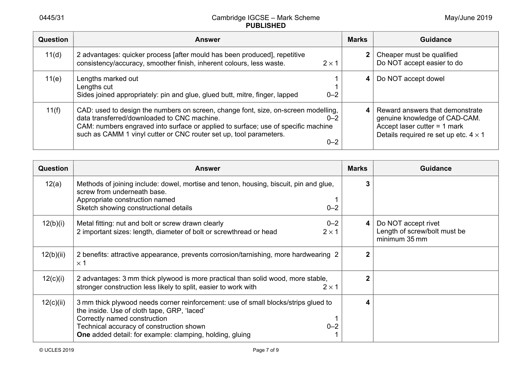
Mark scheme: 11(a)(i) Hardwearing, tough, close grain, does not split easily, good finish, doesn’t chip easily, can be bent to shape, non-toxic, aesthetically pleasing 2 × 1 2 Do NOT accept strong or durable, cheap, easy to work, lightweight 11(a)(ii) 3 marking out tools: steel rule, try square, engineers try square, marking knife, mortise/marking gauges 3 × 1 3 Do NOT accept metalworking tools or any form of felt tip/marker pens 11(a)(iii) Slot cut out: chisel and mallet, mortise machine or drilled holes chiselled out, plunge router, check depth of holes 2 × 1 stages Award 1 mark for technical accuracy 1 3 For example: router or mortise machine =1 + details can = 3 marks 11(b)(i) Brass, aluminium, copper, duralumin, gilding metal 1 11(b)(ii) Can provide an attractive clear finish that does not corrode/rust 1 Accept takes a long time to corrode 11(c) Method 1: Between centres wood turning. Award 0–5 marks for each relevant detail in process including: preparing the wood before setting up, correct set up, use of gouges/scrapers to make round, parting off. Method 2: Make each disc individually by marking out a circle, cutting to shape and finishing on disc sander, hole drilled, method of achieving identical discs 5 × 1 Method 3: Use of hole saw. Accurate sketch of hole saw and mandrel 0–2, fitted into drill 1, wood held securely 1, hole drilled and disc removed 1. 5 Question Answer Marks Guidance 11(d) 2 advantages: quicker process [after mould has been produced], repetitive consistency/accuracy, smoother finish, inherent colours, less waste. 2 × 1 2 Cheaper must be qualified Do NOT accept easier to do 11(e) Lengths marked out 1 Lengths cut 1 Sides joined appropriately: pin and glue, glued butt, mitre, finger, lapped 0–2 4 Do NOT accept dowel 11(f) CAD: used to design the numbers on screen, change font, size, on-screen modelling, data transferred/downloaded to CNC machine. 0–2 CAM: numbers engraved into surface or applied to surface; use of specific machine such as CAMM 1 vinyl cutter or CNC router set up, tool parameters. 0–2 4 Reward answers that demonstrate genuine knowledge of CAD-CAM. Accept laser cutter = 1 mark Details required re set up etc. 4 × 1
Q12 · An incomplete design for a reading lamp to be made in a school workshop
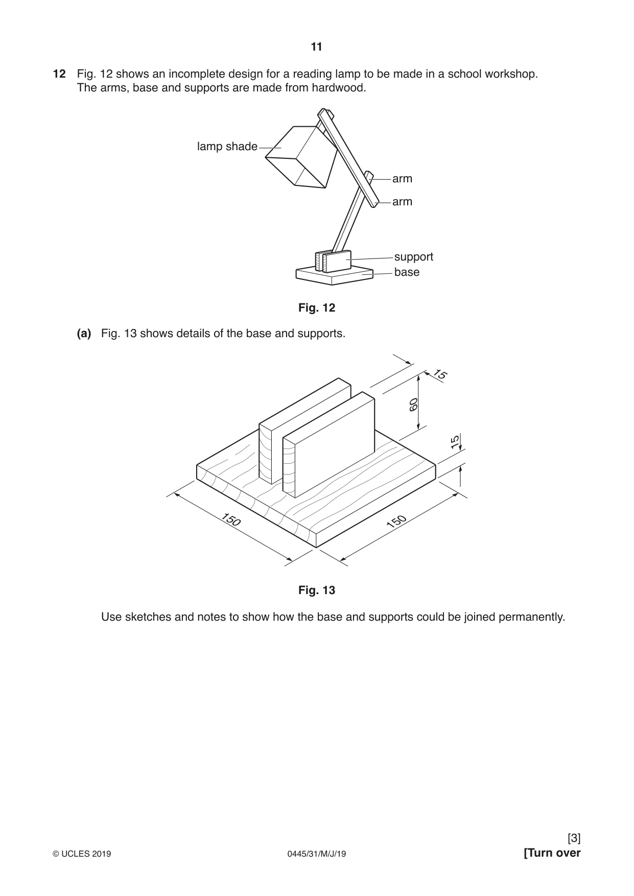
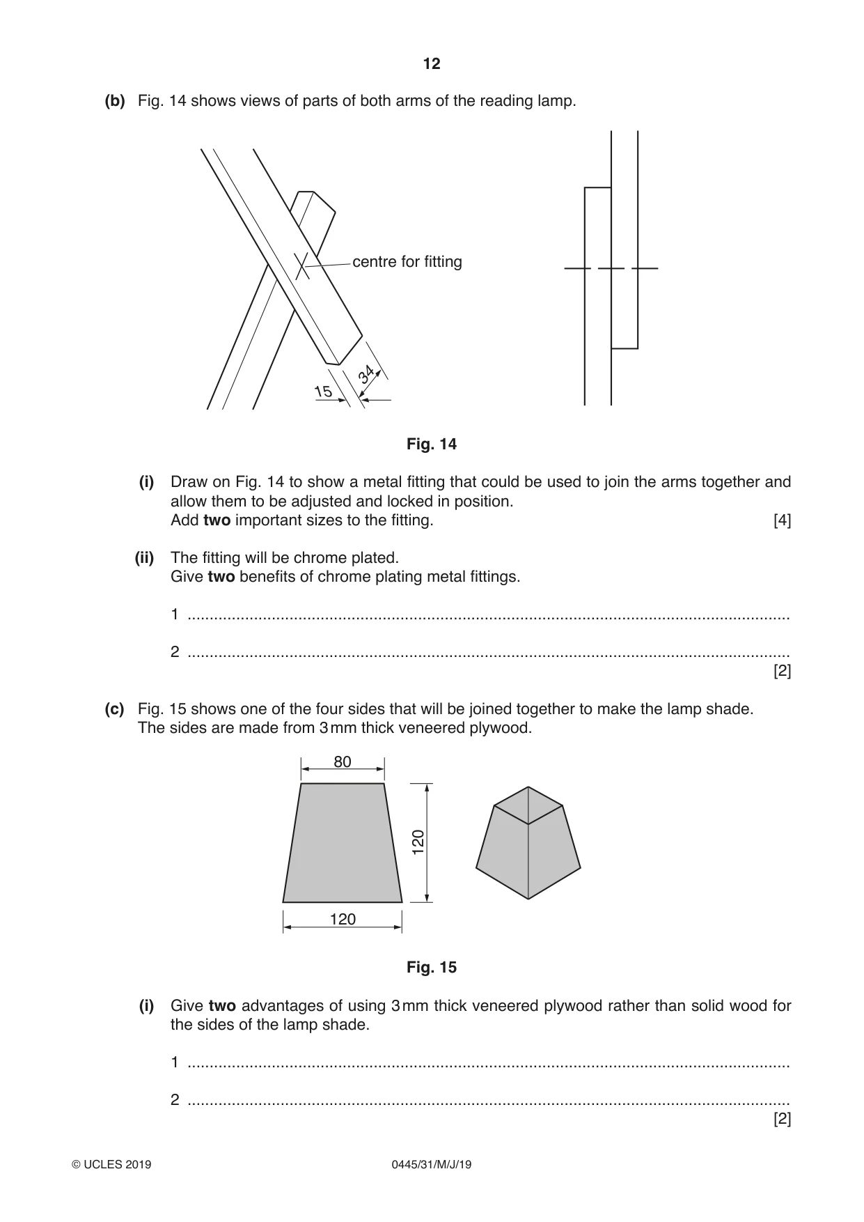
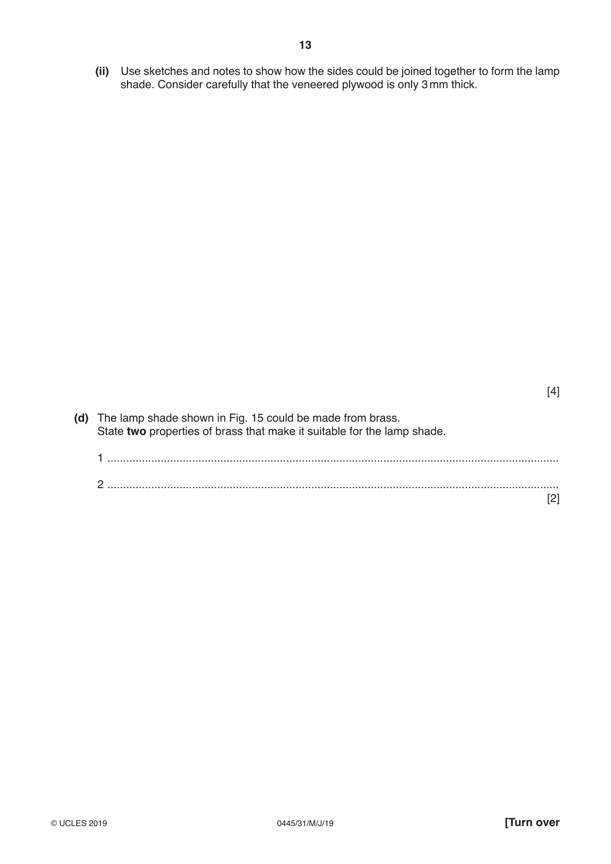
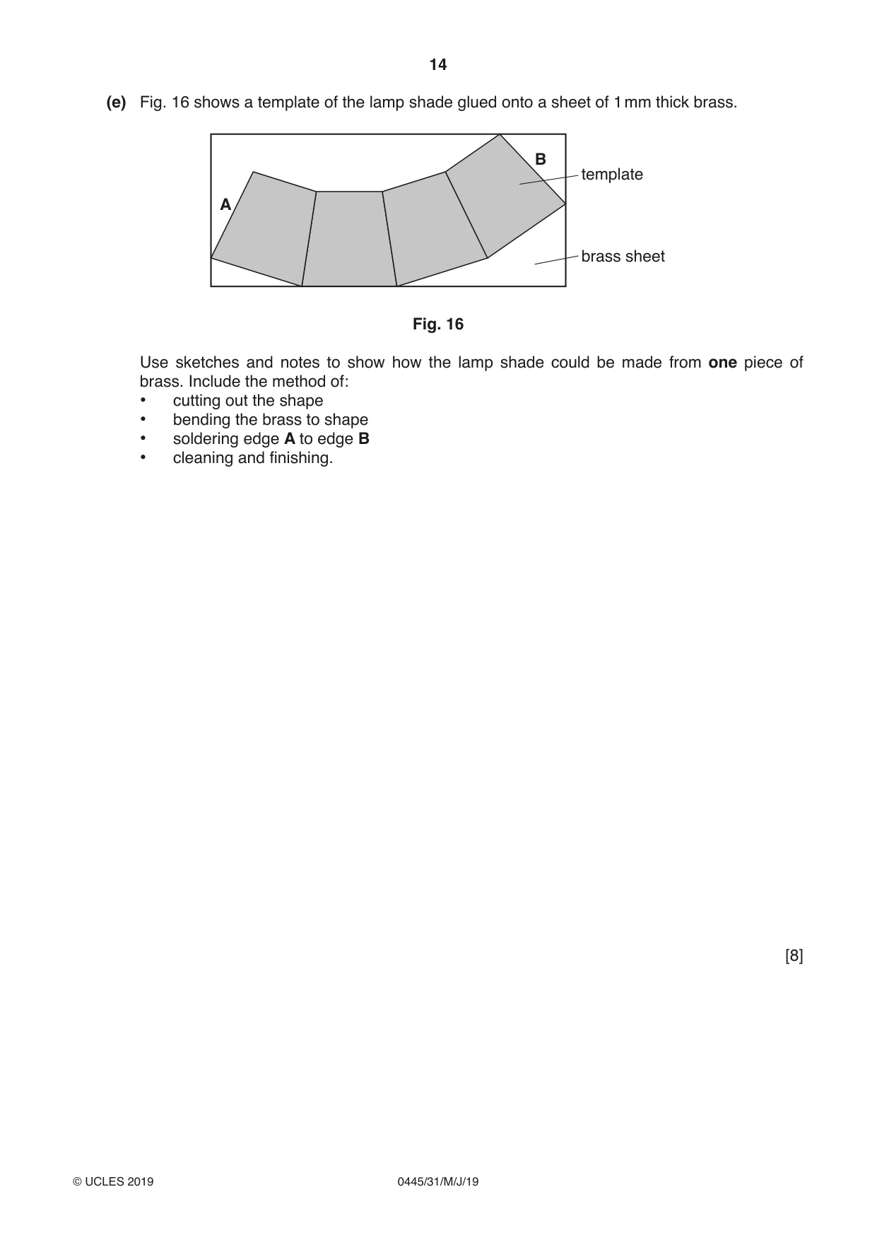
12 Fig. 12 shows an incomplete design for a reading lamp to be made in a school workshop. The arms, base and supports are made from hardwood. lamp shade arm arm support base Fig. 12 (a) Fig. 13 shows details of the base and supports. 15 60 15 150 150 Fig. 13 Use sketches and notes to show how the base and supports could be joined permanently. (b) Fig. 14 shows views of parts of both arms of the reading lamp. centre for fitting 34 15 Fig. 14 (i) Draw on Fig. 14 to show a metal fitting that could be used to join the arms together and allow them to be adjusted and locked in position. Add two important sizes to the fitting. [4] (ii) The fitting will be chrome plated. Give two benefits of chrome plating metal fittings. 1 ........................................................................................................................................ 2 ........................................................................................................................................ [2] (c) Fig. 15 shows one of the four sides that will be joined together to make the lamp shade. The sides are made from 3 mm thick veneered plywood. 80 120 120 Fig. 15 (i) Give two advantages of using 3 mm thick veneered plywood rather than solid wood for the sides of the lamp shade. 1 ........................................................................................................................................ 2 ........................................................................................................................................ [2] (ii) Use sketches and notes to show how the sides could be joined together to form the lamp shade. Consider carefully that the veneered plywood is only 3 mm thick. [4] (d) The lamp shade shown in Fig. 15 could be made from brass. State two properties of brass that make it suitable for the lamp shade. 1 ................................................................................................................................................ 2 ................................................................................................................................................ [2] (e) Fig. 16 shows a template of the lamp shade glued onto a sheet of 1 mm thick brass. B template A brass sheet Fig. 16 Use sketches and notes to show how the lamp shade could be made from one piece of brass. Include the method of: • cutting out the shape • bending the brass to shape • soldering edge A to edge B • cleaning and finishing. [8]
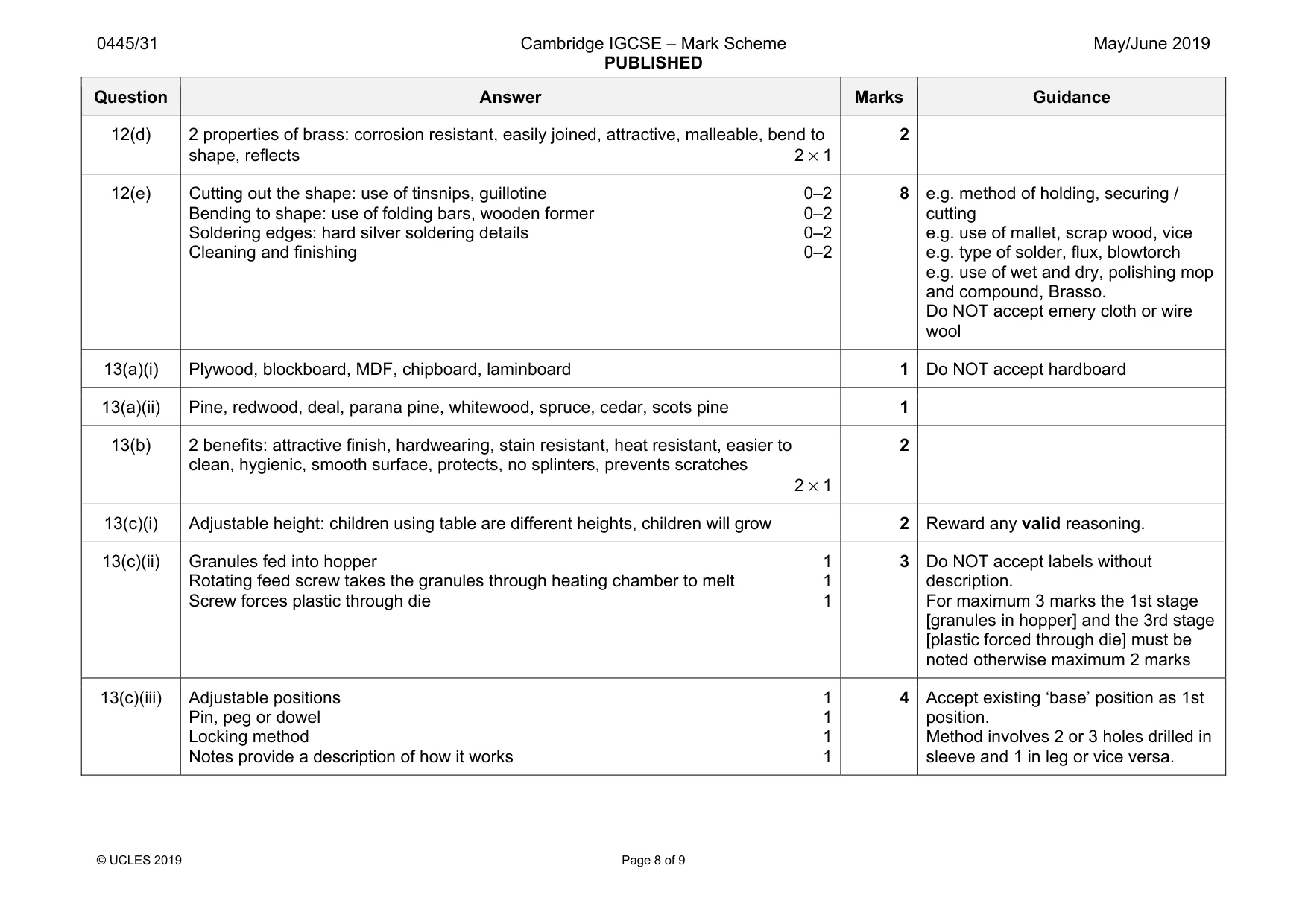
Mark scheme: 12(a) Methods of joining include: dowel, mortise and tenon, housing, biscuit, pin and glue, screw from underneath base. Appropriate construction named 1 Sketch showing constructional details 0–2 3 12(b)(i) Metal fitting: nut and bolt or screw drawn clearly 0–2 2 important sizes: length, diameter of bolt or screwthread or head 2 × 1 4 Do NOT accept rivet Length of screw/bolt must be minimum 35 mm 12(b)(ii) 2 benefits: attractive appearance, prevents corrosion/tarnishing, more hardwearing 2 × 1 2 12(c)(i) 2 advantages: 3 mm thick plywood is more practical than solid wood, more stable, stronger construction less likely to split, easier to work with 2 × 1 2 12(c)(ii) 3 mm thick plywood needs corner reinforcement: use of small blocks/strips glued to the inside. Use of cloth tape, GRP, ‘laced’ Correctly named construction 1 Technical accuracy of construction shown 0–2 One added detail: for example: clamping, holding, gluing 1 4 Question Answer Marks Guidance 12(d) 2 properties of brass: corrosion resistant, easily joined, attractive, malleable, bend to shape, reflects 2 × 1 2 12(e) Cutting out the shape: use of tinsnips, guillotine 0–2 Bending to shape: use of folding bars, wooden former 0–2 Soldering edges: hard silver soldering details 0–2 Cleaning and finishing 0–2 8 e.g. method of holding, securing / cutting e.g. use of mallet, scrap wood, vice e.g. type of solder, flux, blowtorch e.g. use of wet and dry, polishing mop and compound, Brasso. Do NOT accept emery cloth or wire wool
Q13 · Views of a children’s play table
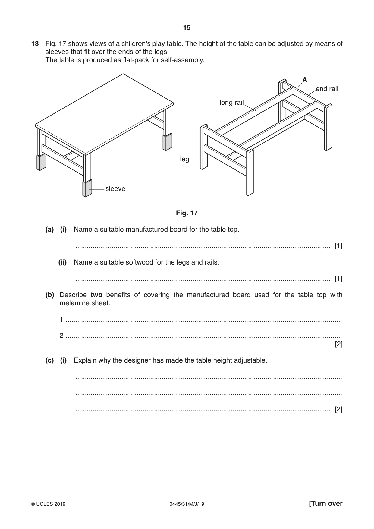
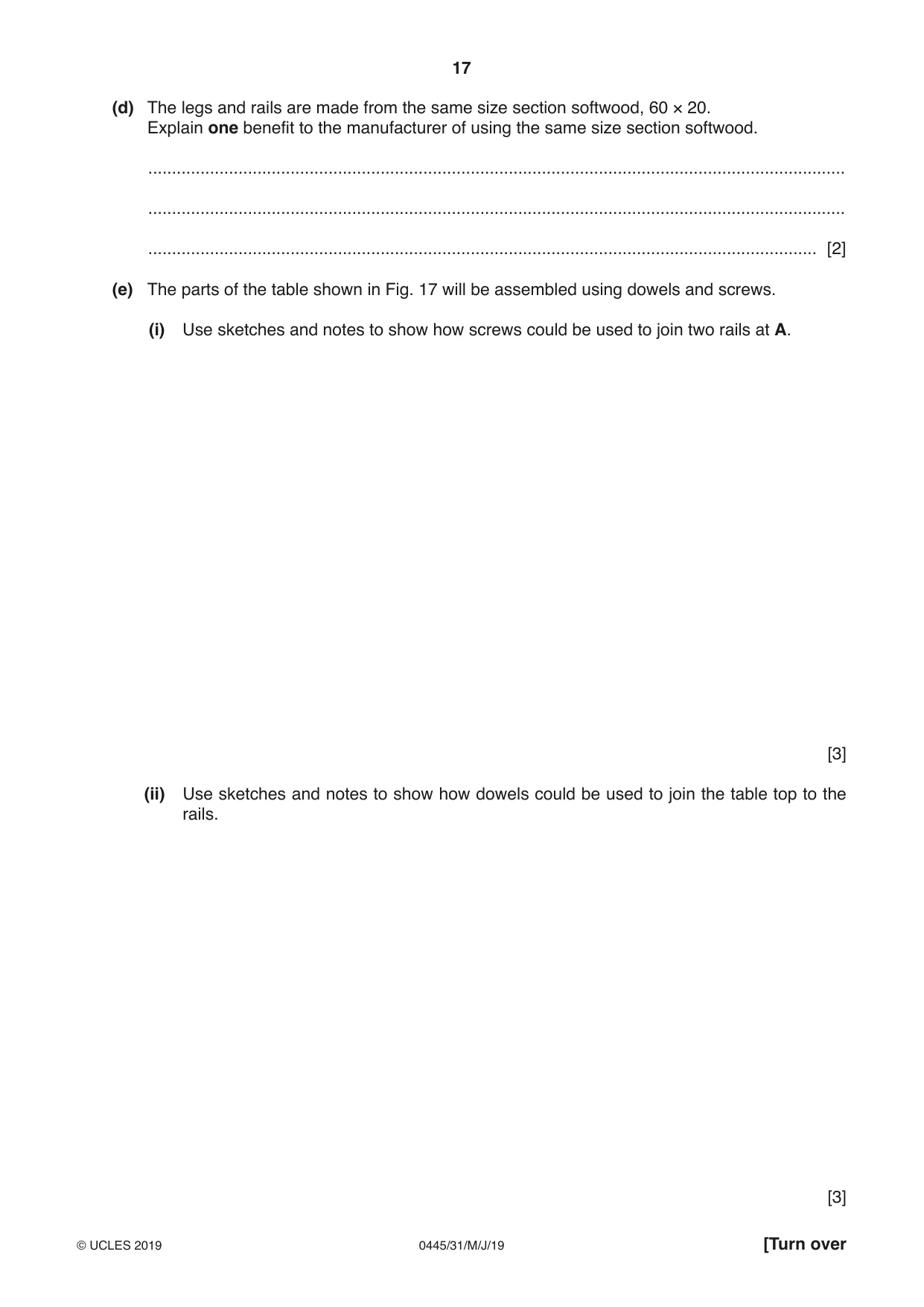
13 Fig. 17 shows views of a children’s play table. The height of the table can be adjusted by means of sleeves that fit over the ends of the legs. The table is produced as flat-pack for self-assembly. A end rail long rail leg sleeve Fig. 17 (a) (i) Name a suitable manufactured board for the table top. ..................................................................................................................................... [1] (ii) Name a suitable softwood for the legs and rails. ..................................................................................................................................... [1] (b) Describe two benefits of covering the manufactured board used for the table top with melamine sheet. 1 ................................................................................................................................................ 2 ................................................................................................................................................ [2] (c) (i) Explain why the designer has made the table height adjustable. ........................................................................................................................................... ........................................................................................................................................... ..................................................................................................................................... [2] (ii) The height of the table can be adjusted by means of sleeves that fit over the ends of the legs. The sleeve shown below will be produced by the extrusion process. 150 65 22 Fig. 18 shows part of an extrusion moulding machine. Add notes to Fig. 18 to describe the extrusion process. Fig. 18 [3] (iii) The height of the table can be adjusted by moving the sleeve up or down and locking it in position. Use sketches and notes to show how the table could be set at three different heights. Include details of any fittings and materials used. [4] (d) The legs and rails are made from the same size section softwood, 60 × 20. Explain one benefit to the manufacturer of using the same size section softwood. ................................................................................................................................................... ................................................................................................................................................... ............................................................................................................................................. [2] (e) The parts of the table shown in Fig. 17 will be assembled using dowels and screws. (i) Use sketches and notes to show how screws could be used to join two rails at A. [3] (ii) Use sketches and notes to show how dowels could be used to join the table top to the rails. [3]
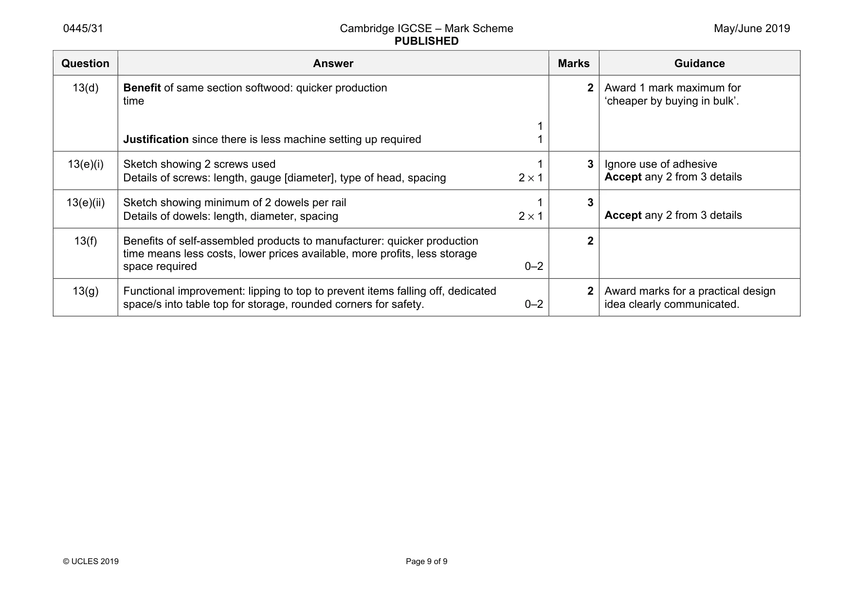
Mark scheme: 13(a)(i) Plywood, blockboard, MDF, chipboard, laminboard 1 Do NOT accept hardboard 13(a)(ii) Pine, redwood, deal, parana pine, whitewood, spruce, cedar, scots pine 1 13(b) 2 benefits: attractive finish, hardwearing, stain resistant, heat resistant, easier to clean, hygienic, smooth surface, protects, no splinters, prevents scratches 2 × 1 2 13(c)(i) Adjustable height: children using table are different heights, children will grow 2 Reward any valid reasoning. 13(c)(ii) Granules fed into hopper 1 Rotating feed screw takes the granules through heating chamber to melt 1 Screw forces plastic through die 1 3 Do NOT accept labels without description. For maximum 3 marks the 1st stage [granules in hopper] and the 3rd stage [plastic forced through die] must be noted otherwise maximum 2 marks 13(c)(iii) Adjustable positions 1 Pin, peg or dowel 1 Locking method 1 Notes provide a description of how it works 1 4 Accept existing ‘base’ position as 1st position. Method involves 2 or 3 holes drilled in sleeve and 1 in leg or vice versa. Question Answer Marks Guidance 13(d) Benefit of same section softwood: quicker production time 1 Justification since there is less machine setting up required 1 2 Award 1 mark maximum for ‘cheaper by buying in bulk’. 13(e)(i) Sketch showing 2 screws used 1 Details of screws: length, gauge [diameter], type of head, spacing 2 × 1 3 Ignore use of adhesive Accept any 2 from 3 details 13(e)(ii) Sketch showing minimum of 2 dowels per rail 1 Details of dowels: length, diameter, spacing 2 × 1 3 Accept any 2 from 3 details 13(f) Benefits of self-assembled products to manufacturer: quicker production time means less costs, lower prices available, more profits, less storage space required 0–2 2 13(g) Functional improvement: lipping to top to prevent items falling off, dedicated space/s into table top for storage, rounded corners for safety. 0–2 2 Award marks for a practical design idea clearly communicated.
What was in this paper
The subtopics covered by these 13 questions, and how many questions each got. Open one in a new tab to see every Cambridge question on it.
What you needed in this session
Cambridge’s own grade thresholds for 2019 May/June, Paper 3 · Variant 1. A higher threshold means an easier paper — the bar moves with how the cohort did.