Cambridge IGCSE Design and Technology 0445 — 2018 Oct/Nov Paper 3 · Variant 2
0445/32/O/N/18 · 13 questions · 50 marks · ≈56 min
The question paper and its mark scheme, free to read here and free to download. This is Cambridge’s own paper, exactly as it was sat.
Question paper20 pages
Mark scheme6 pages
Answers below. Sit the paper first if you are practising.
Questions as text
Q1 · A length of wood marked to the required width
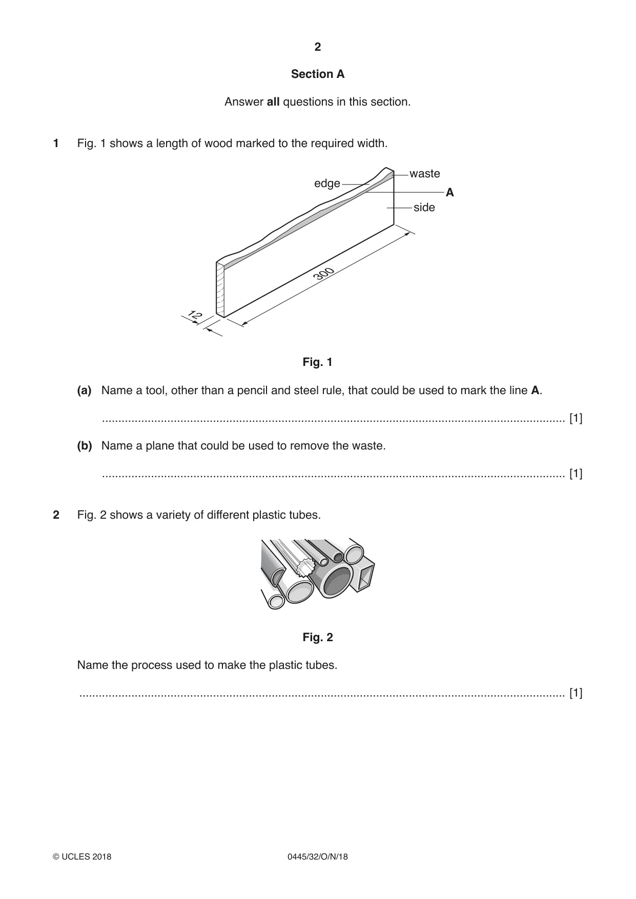
1 Fig. 1 shows a length of wood marked to the required width. waste edge A side 300 12 Fig. 1 (a) Name a tool, other than a pencil and steel rule, that could be used to mark the line A. .............................................................................................................................................. [1] (b) Name a plane that could be used to remove the waste. .............................................................................................................................................. [1]
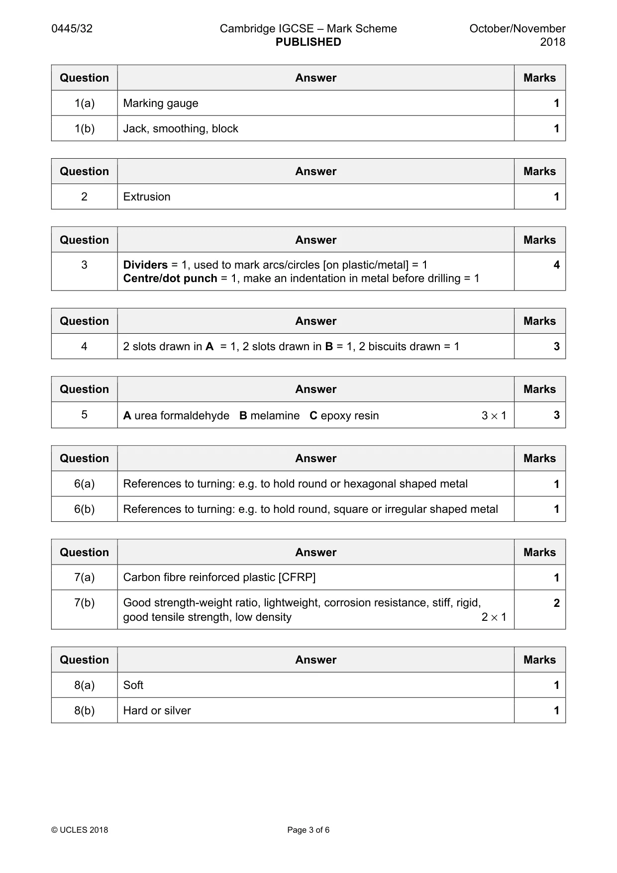
Mark scheme: Question Answer Marks 1(a) Marking gauge 1 1(b) Jack, smoothing, block 1
Q2 · A variety of different plastic tubes
2 Fig. 2 shows a variety of different plastic tubes. Fig. 2 Name the process used to make the plastic tubes. ..................................................................................................................................................... [1]
Mark scheme: 2 Extrusion 1
Q3 · Complete the table below by naming each tool and describing a specific use for each
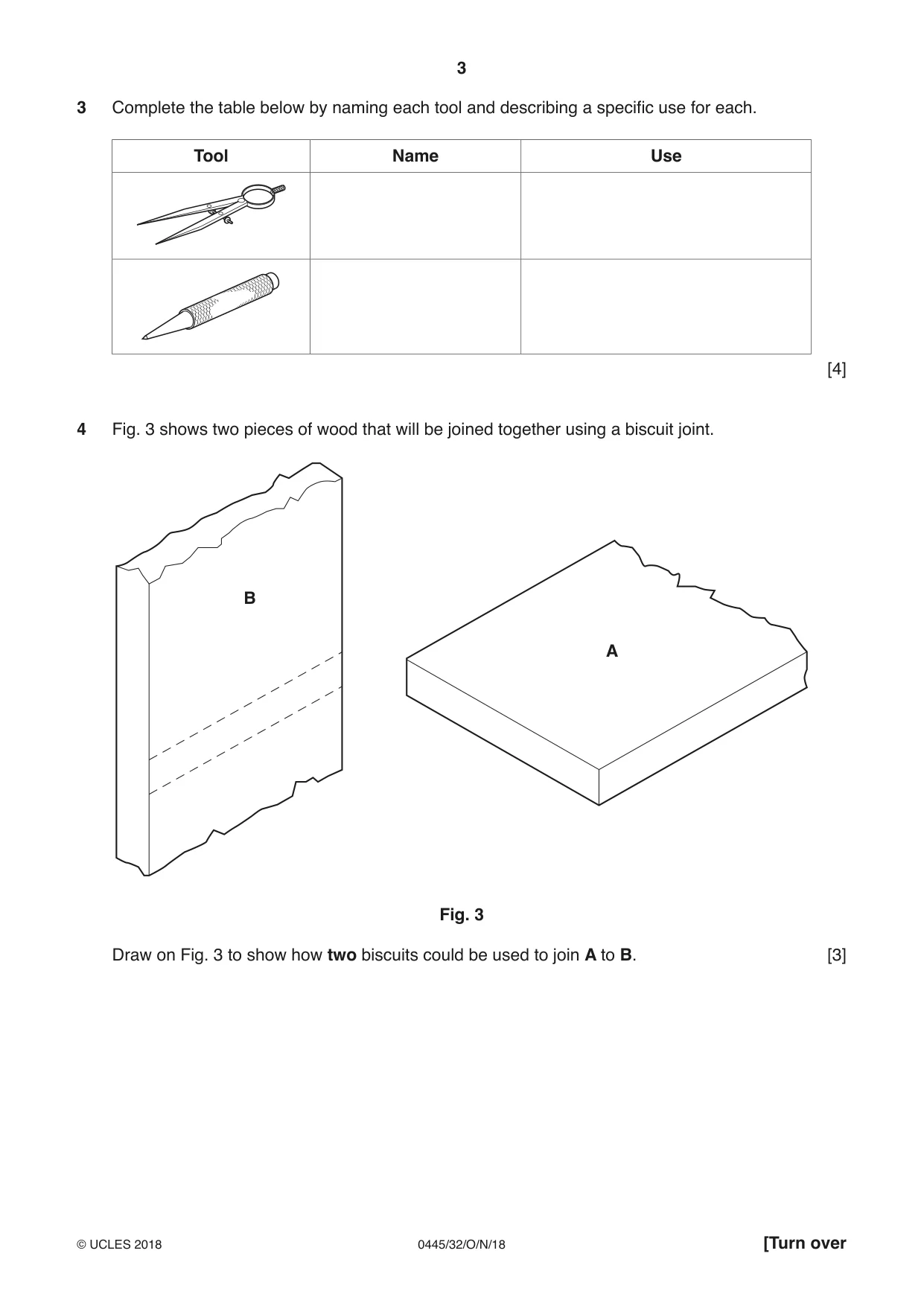
3 Complete the table below by naming each tool and describing a specific use for each. Tool Name Use [4]
Mark scheme: 3 Dividers = 1, used to mark arcs/circles [on plastic/metal] = 1 4 Centre/dot punch = 1, make an indentation in metal before drilling = 1
Q4 · Two pieces of wood that will be joined together using a biscuit joint
4 Fig. 3 shows two pieces of wood that will be joined together using a biscuit joint. B A Fig. 3 Draw on Fig. 3 to show how two biscuits could be used to join A to B. [3]
Mark scheme: 4 2 slots drawn in A = 1, 2 slots drawn in B = 1, 2 biscuits drawn = 1 3
Q5 · Three products made from different thermosetting plastics
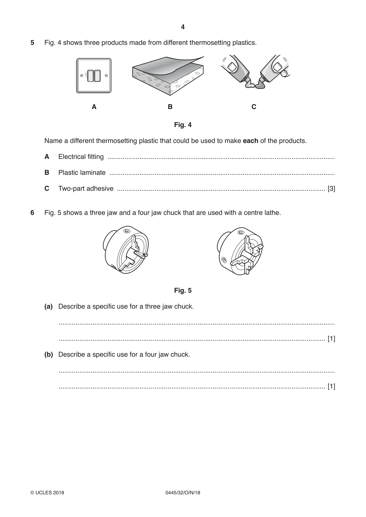
5 Fig. 4 shows three products made from different thermosetting plastics. A B C Fig. 4 Name a different thermosetting plastic that could be used to make each of the products. A Electrical fitting ......................................................................................................................... B Plastic laminate ........................................................................................................................ C Two-part adhesive ............................................................................................................... [3]
Mark scheme: 5 A urea formaldehyde B melamine C epoxy resin 3 × 1 3
Q6 · A three jaw and a four jaw chuck that are used with a centre lathe
6 Fig. 5 shows a three jaw and a four jaw chuck that are used with a centre lathe. Fig. 5 (a) Describe a specific use for a three jaw chuck. ................................................................................................................................................... .............................................................................................................................................. [1] (b) Describe a specific use for a four jaw chuck. ................................................................................................................................................... .............................................................................................................................................. [1]
Mark scheme: 6(a) References to turning: e.g. to hold round or hexagonal shaped metal 1 6(b) References to turning: e.g. to hold round, square or irregular shaped metal 1
Q7 · A pair of shin pads used by hockey players
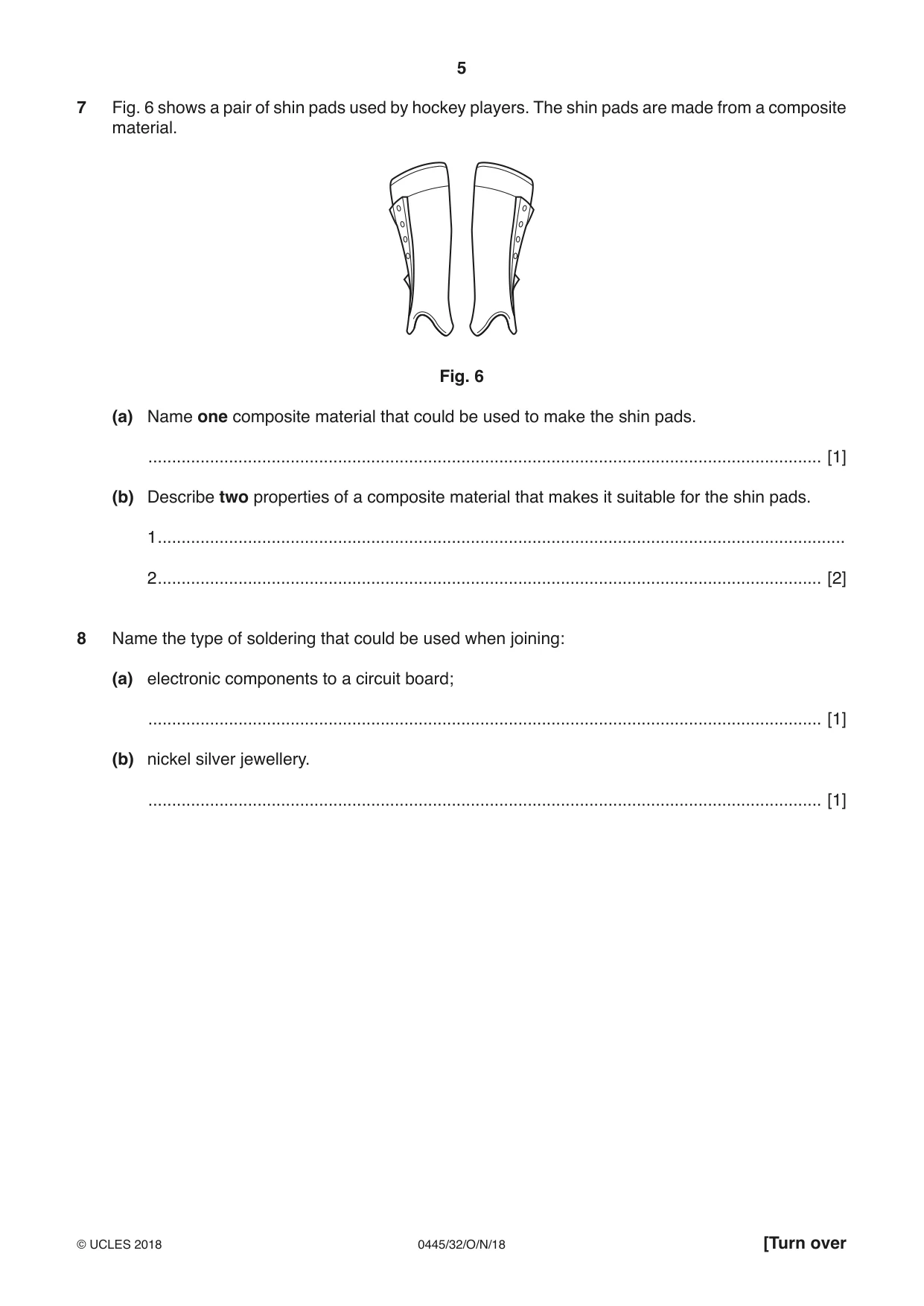
7 Fig. 6 shows a pair of shin pads used by hockey players. The shin pads are made from a composite material. Fig. 6 (a) Name one composite material that could be used to make the shin pads. .............................................................................................................................................. [1] (b) Describe two properties of a composite material that makes it suitable for the shin pads. 1 ................................................................................................................................................. 2 ............................................................................................................................................ [2]
Mark scheme: 7(a) Carbon fibre reinforced plastic [CFRP] 1 7(b) Good strength-weight ratio, lightweight, corrosion resistance, stiff, rigid, 2 good tensile strength, low density 2 × 1
Q8 · Name the type of soldering that could be used when joining: (a) electronic components to…
8 Name the type of soldering that could be used when joining: (a) electronic components to a circuit board; .............................................................................................................................................. [1] (b) nickel silver jewellery. .............................................................................................................................................. [1]
Mark scheme: 8(a) Soft 1 8(b) Hard or silver 1
Q9 · Part of a leg and rail of a table and a knock-down (KD) fitting
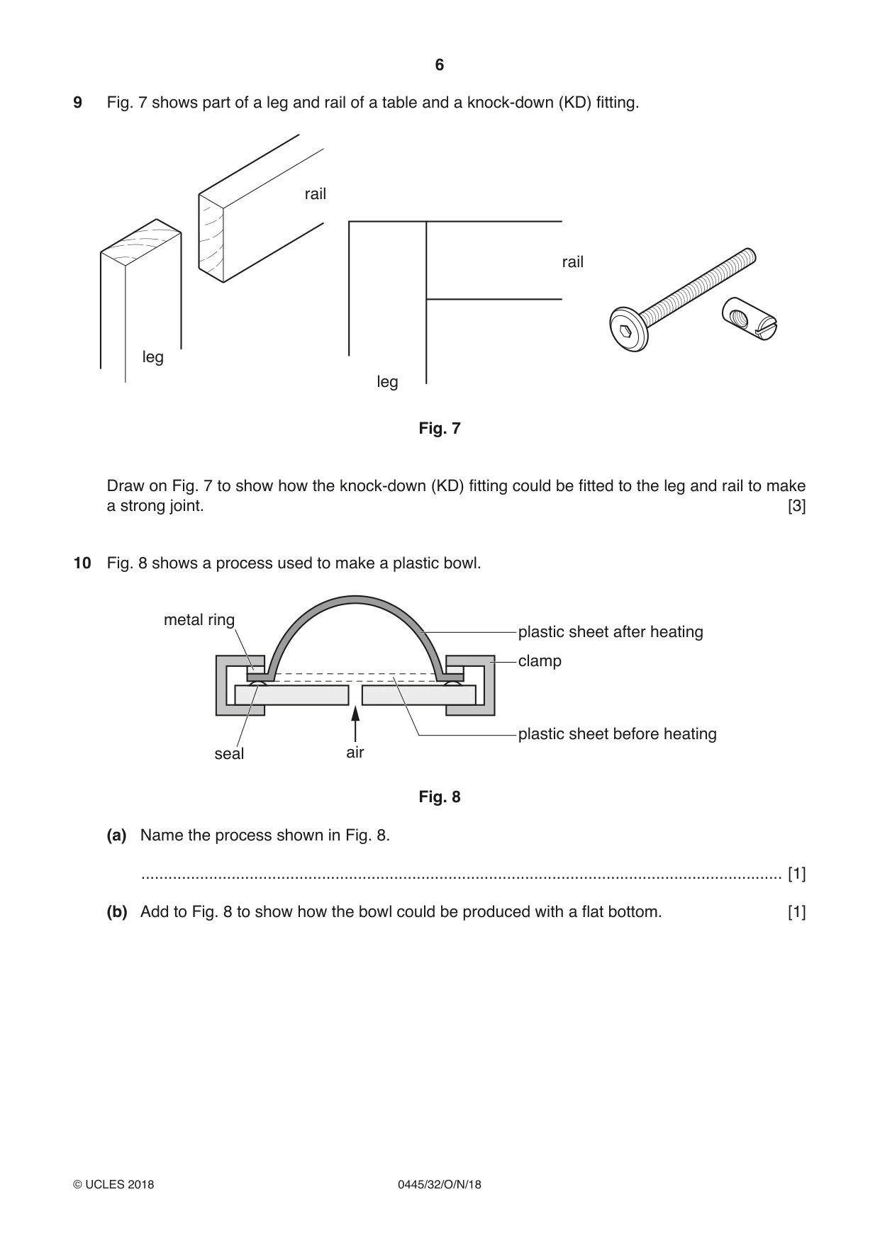
9 Fig. 7 shows part of a leg and rail of a table and a knock-down (KD) fitting. rail rail leg leg Fig. 7 Draw on Fig. 7 to show how the knock-down (KD) fitting could be fitted to the leg and rail to make a strong joint. [3]
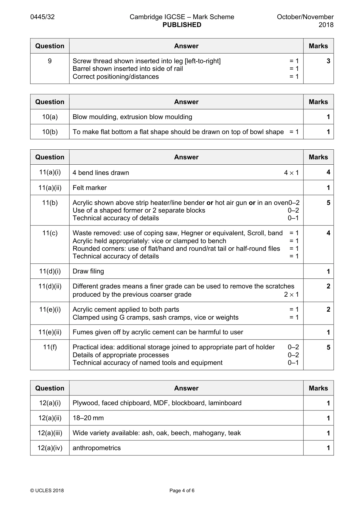
Mark scheme: 9 Screw thread shown inserted into leg [left-to-right] = 1 3 Barrel shown inserted into side of rail = 1 Correct positioning/distances = 1
Q10 · A process used to make a plastic bowl
10 Fig. 8 shows a process used to make a plastic bowl. metal ring plastic sheet after heating clamp plastic sheet before heating seal air Fig. 8 (a) Name the process shown in Fig. 8. .............................................................................................................................................. [1] (b) Add to Fig. 8 to show how the bowl could be produced with a flat bottom. [1]
Mark scheme: 10(a) Blow moulding, extrusion blow moulding 1 10(b) To make flat bottom a flat shape should be drawn on top of bowl shape = 1 1
Q11 · Views of a toothbrush holder made from 4 mm thick acrylic
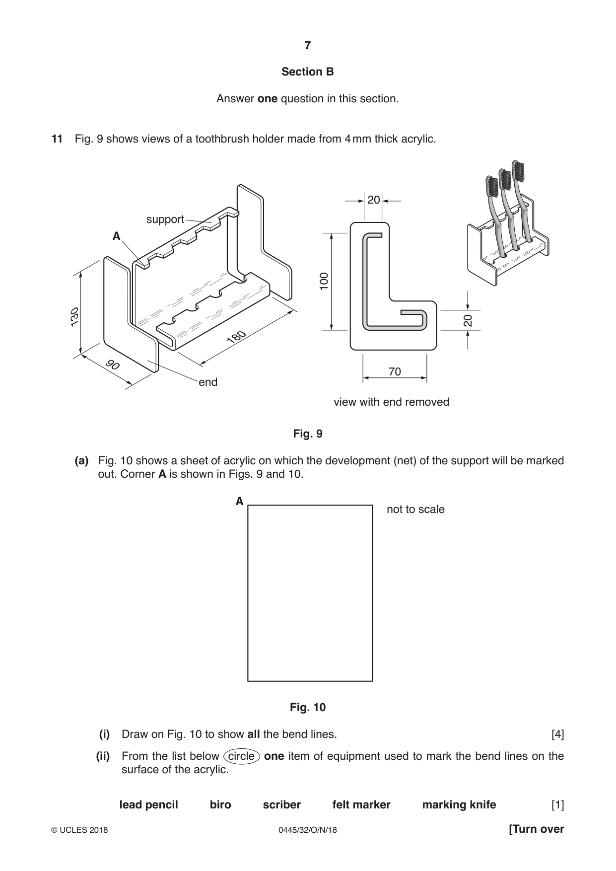
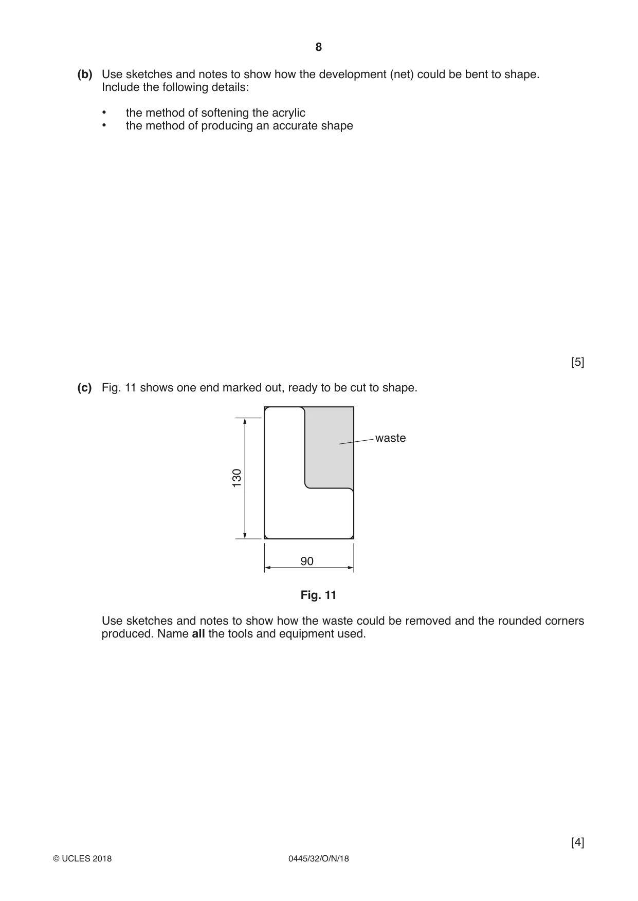
11 Fig. 9 shows views of a toothbrush holder made from 4 mm thick acrylic. 20 support A 100 20 130 180 90 70 end view with end removed Fig. 9 (a) Fig. 10 shows a sheet of acrylic on which the development (net) of the support will be marked out. Corner A is shown in Figs. 9 and 10. A not to scale Fig. 10 (i) Draw on Fig. 10 to show all the bend lines. [4] (ii) From the list below circle one item of equipment used to mark the bend lines on the surface of the acrylic. lead pencil biro scriber felt marker marking knife [1] (b) Use sketches and notes to show how the development (net) could be bent to shape. Include the following details: • the method of softening the acrylic • the method of producing an accurate shape [5] (c) Fig. 11 shows one end marked out, ready to be cut to shape. waste 130 90 Fig. 11 Use sketches and notes to show how the waste could be removed and the rounded corners produced. Name all the tools and equipment used. [4] (d) The edges of the ends and support will be self-finished to a high quality before the parts are joined together. (i) Name the method of filing used to make the edges smooth. ...................................................................................................................................... [1] (ii) Explain why two different grades of wet and dry (silicon carbide) paper would be used when self-finishing the edges. ........................................................................................................................................... ........................................................................................................................................... ...................................................................................................................................... [2] (e) The support will be joined to the ends by using acrylic cement. (i) Describe how the acrylic cement would be applied and how the parts would be held together while the acrylic cement sets. ........................................................................................................................................... ........................................................................................................................................... ...................................................................................................................................... [2] (ii) State why it is important to work in a well-ventilated area when using acrylic cement. ...................................................................................................................................... [1] (f) Use sketches and notes to show how the toothbrush holder could be modified so that a tube of toothpaste could be stored. Describe how the modification could be made in a school workshop. Name all tools and equipment used. [5]
Mark scheme: 11(a)(i) 4 bend lines drawn 4 × 1 4 11(a)(ii) Felt marker 1 11(b) Acrylic shown above strip heater/line bender or hot air gun or in an oven0–2 5 Use of a shaped former or 2 separate blocks 0–2 Technical accuracy of details 0–1 11(c) Waste removed: use of coping saw, Hegner or equivalent, Scroll, band = 1 4 Acrylic held appropriately: vice or clamped to bench = 1 Rounded corners: use of flat/hand and round/rat tail or half-round files = 1 Technical accuracy of details = 1 11(d)(i) Draw filing 1 11(d)(ii) Different grades means a finer grade can be used to remove the scratches 2 produced by the previous coarser grade 2 × 1 11(e)(i) Acrylic cement applied to both parts = 1 2 Clamped using G cramps, sash cramps, vice or weights = 1 11(e)(ii) Fumes given off by acrylic cement can be harmful to user 1 11(f) Practical idea: additional storage joined to appropriate part of holder 0–2 5 Details of appropriate processes 0–2 Technical accuracy of named tools and equipment 0–1
Q12 · An incomplete design of a desk
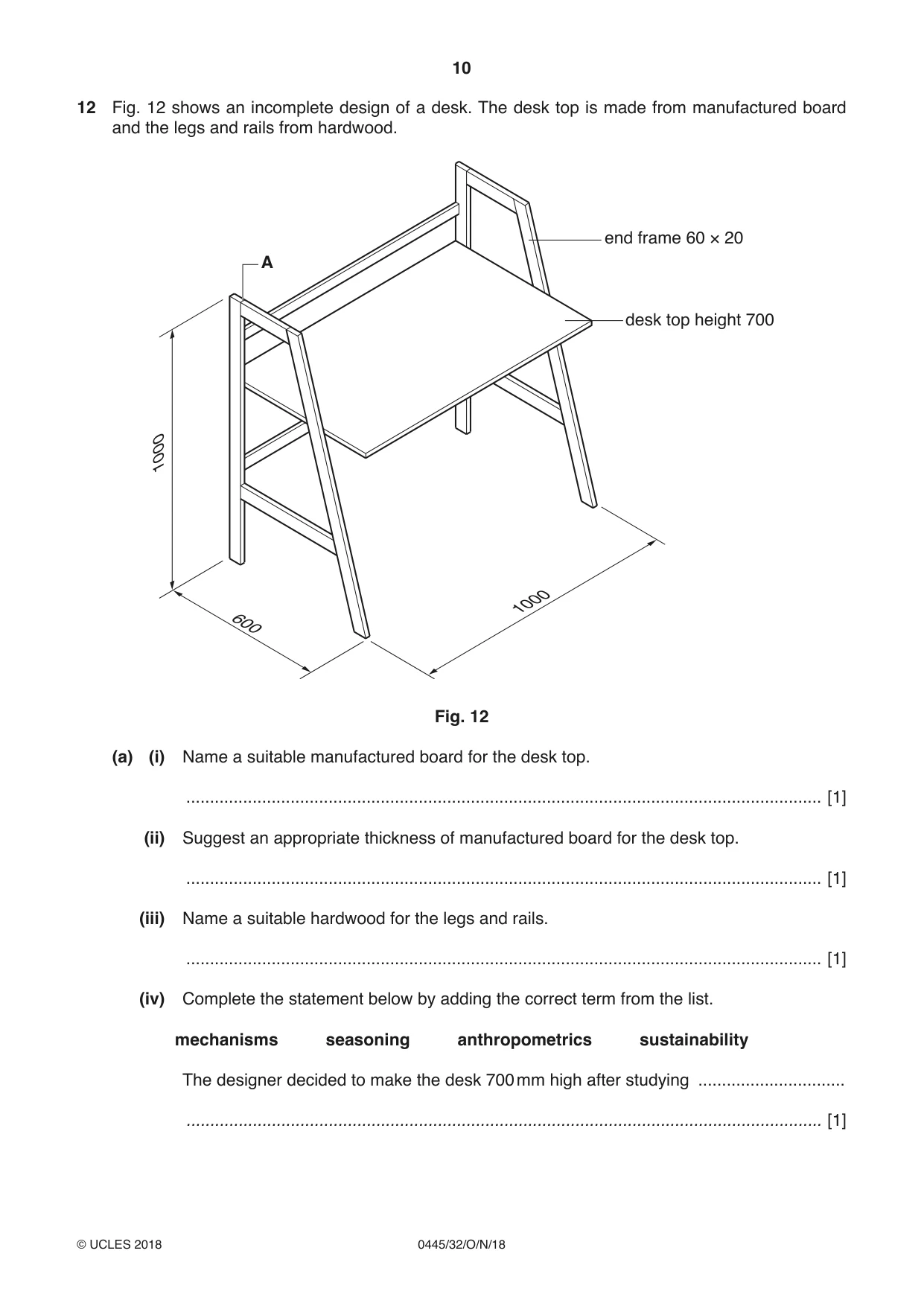
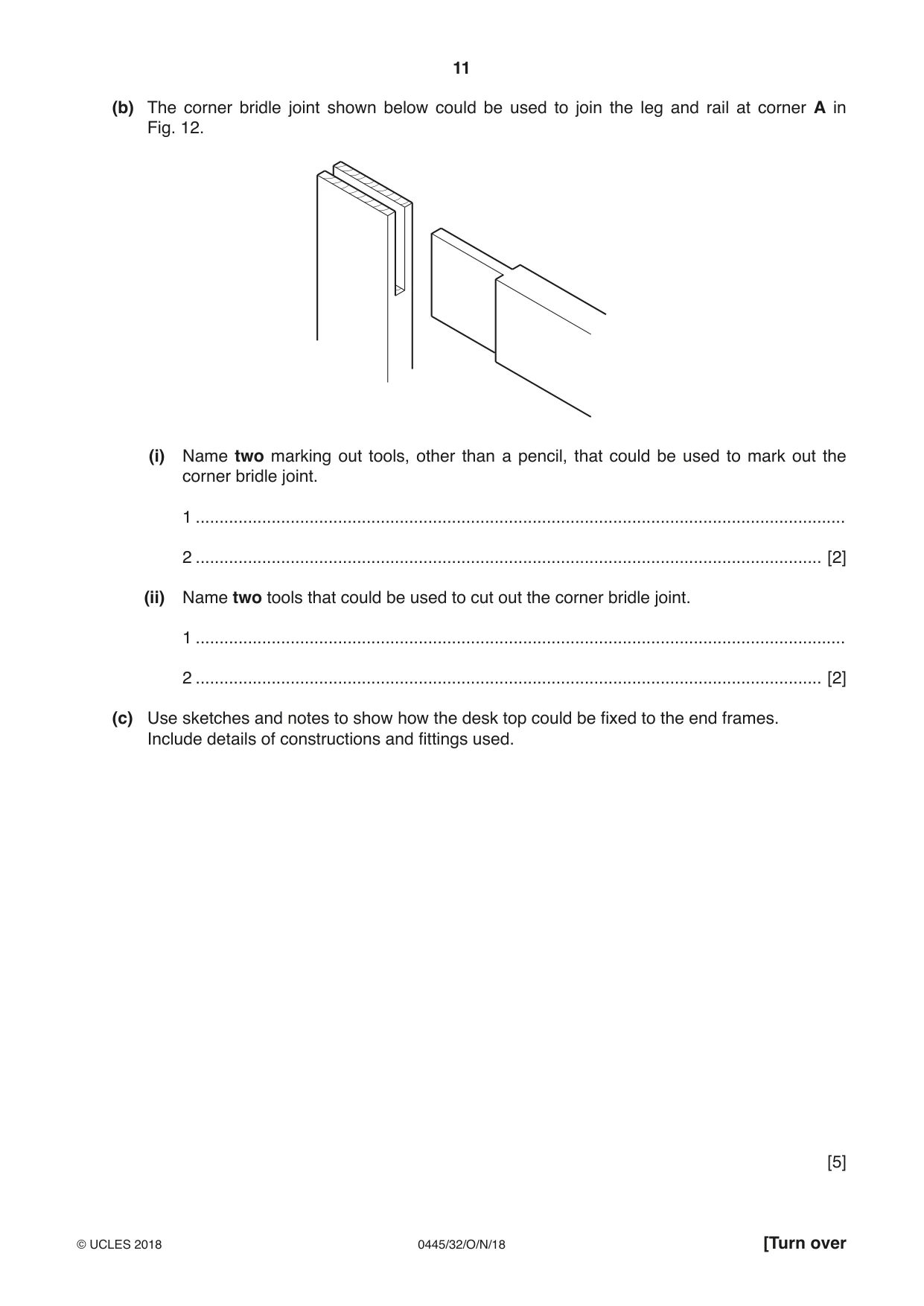
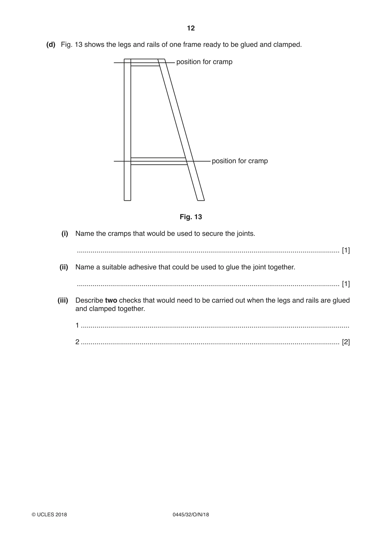
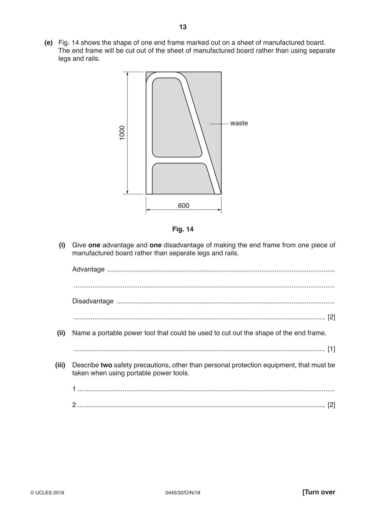
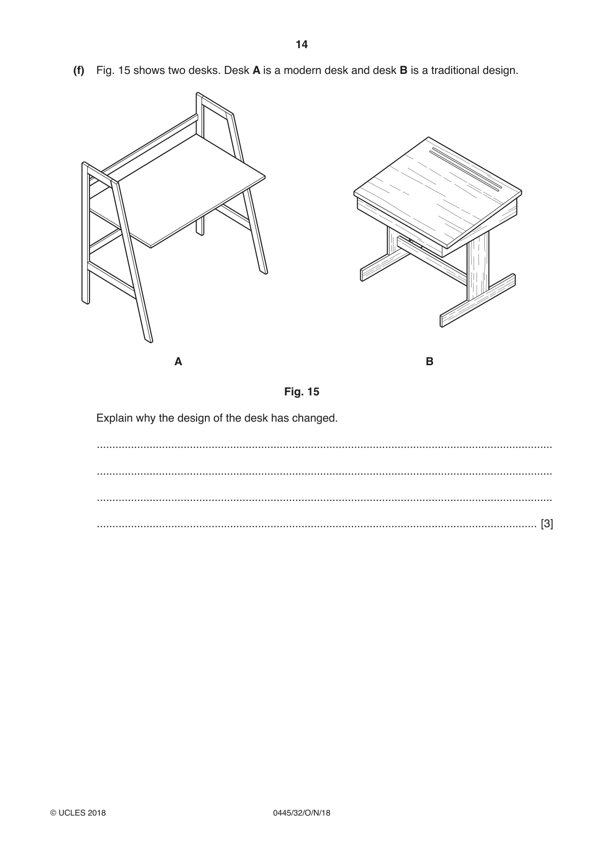
12 Fig. 12 shows an incomplete design of a desk. The desk top is made from manufactured board and the legs and rails from hardwood. end frame 60 × 20 A desk top height 700 1000 1000 600 Fig. 12 (a) (i) Name a suitable manufactured board for the desk top. ...................................................................................................................................... [1] (ii) Suggest an appropriate thickness of manufactured board for the desk top. ...................................................................................................................................... [1] (iii) Name a suitable hardwood for the legs and rails. ...................................................................................................................................... [1] (iv) Complete the statement below by adding the correct term from the list. mechanisms seasoning anthropometrics sustainability The designer decided to make the desk 700 mm high after studying ............................... ...................................................................................................................................... [1] (b) The corner bridle joint shown below could be used to join the leg and rail at corner A in Fig. 12. (i) Name two marking out tools, other than a pencil, that could be used to mark out the corner bridle joint. 1 ......................................................................................................................................... 2 .................................................................................................................................... [2] (ii) Name two tools that could be used to cut out the corner bridle joint. 1 ......................................................................................................................................... 2 .................................................................................................................................... [2] (c) Use sketches and notes to show how the desk top could be fixed to the end frames. Include details of constructions and fittings used. [5] (d) Fig. 13 shows the legs and rails of one frame ready to be glued and clamped. position for cramp position for cramp Fig. 13 (i) Name the cramps that would be used to secure the joints. ...................................................................................................................................... [1] (ii) Name a suitable adhesive that could be used to glue the joint together. ...................................................................................................................................... [1] (iii) Describe two checks that would need to be carried out when the legs and rails are glued and clamped together. 1 ......................................................................................................................................... 2 .................................................................................................................................... [2] (e) Fig. 14 shows the shape of one end frame marked out on a sheet of manufactured board. The end frame will be cut out of the sheet of manufactured board rather than using separate legs and rails. waste 1000 600 Fig. 14 (i) Give one advantage and one disadvantage of making the end frame from one piece of manufactured board rather than separate legs and rails. Advantage ......................................................................................................................... ........................................................................................................................................... Disadvantage .................................................................................................................... ...................................................................................................................................... [2] (ii) Name a portable power tool that could be used to cut out the shape of the end frame. ...................................................................................................................................... [1] (iii) Describe two safety precautions, other than personal protection equipment, that must be taken when using portable power tools. 1 ......................................................................................................................................... 2 .................................................................................................................................... [2] (f) Fig. 15 shows two desks. Desk A is a modern desk and desk B is a traditional design. A B Fig. 15 Explain why the design of the desk has changed. ................................................................................................................................................... ................................................................................................................................................... ................................................................................................................................................... .............................................................................................................................................. [3]
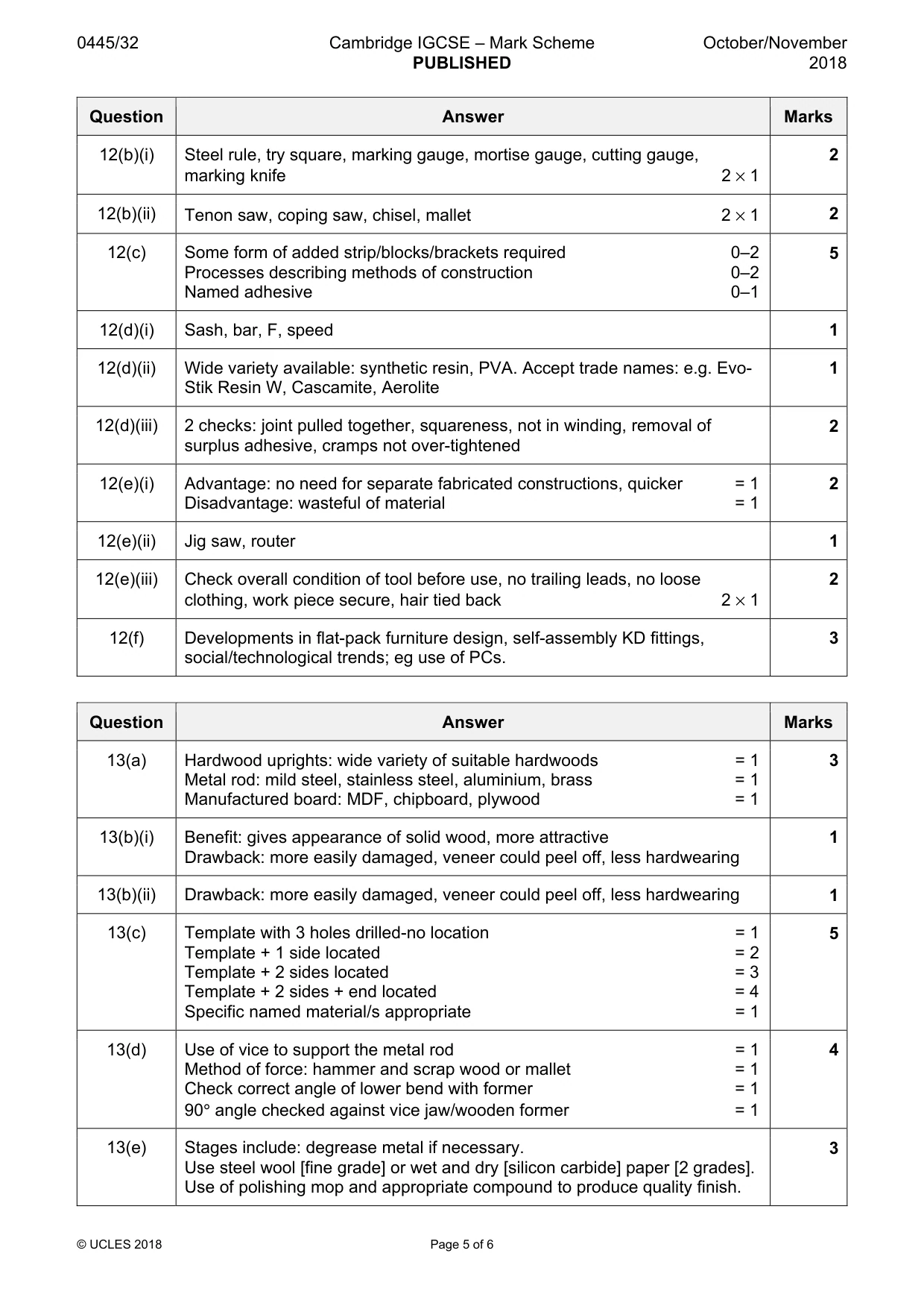
Mark scheme: 12(a)(i) Plywood, faced chipboard, MDF, blockboard, laminboard 1 12(a)(ii) 18–20 mm 1 12(a)(iii) Wide variety available: ash, oak, beech, mahogany, teak 1 12(a)(iv) anthropometrics 1 12(b)(i) Steel rule, try square, marking gauge, mortise gauge, cutting gauge, 2 marking knife 2 × 1 12(b)(ii) Tenon saw, coping saw, chisel, mallet 2 × 1 2 12(c) Some form of added strip/blocks/brackets required 0–2 5 Processes describing methods of construction 0–2 Named adhesive 0–1 12(d)(i) Sash, bar, F, speed 1 12(d)(ii) Wide variety available: synthetic resin, PVA. Accept trade names: e.g. Evo- 1 Stik Resin W, Cascamite, Aerolite 12(d)(iii) 2 checks: joint pulled together, squareness, not in winding, removal of 2 surplus adhesive, cramps not over-tightened 12(e)(i) Advantage: no need for separate fabricated constructions, quicker = 1 2 Disadvantage: wasteful of material = 1 12(e)(ii) Jig saw, router 1 12(e)(iii) Check overall condition of tool before use, no trailing leads, no loose 2 clothing, work piece secure, hair tied back 2 × 1 12(f) Developments in flat-pack furniture design, self-assembly KD fittings, 3 social/technological trends; eg use of PCs.
Q13 · A wall-mounted adjustable shelving system
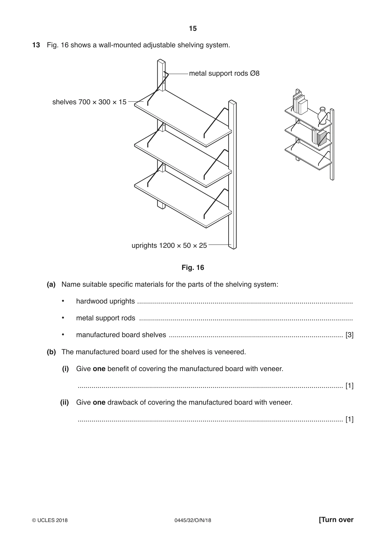
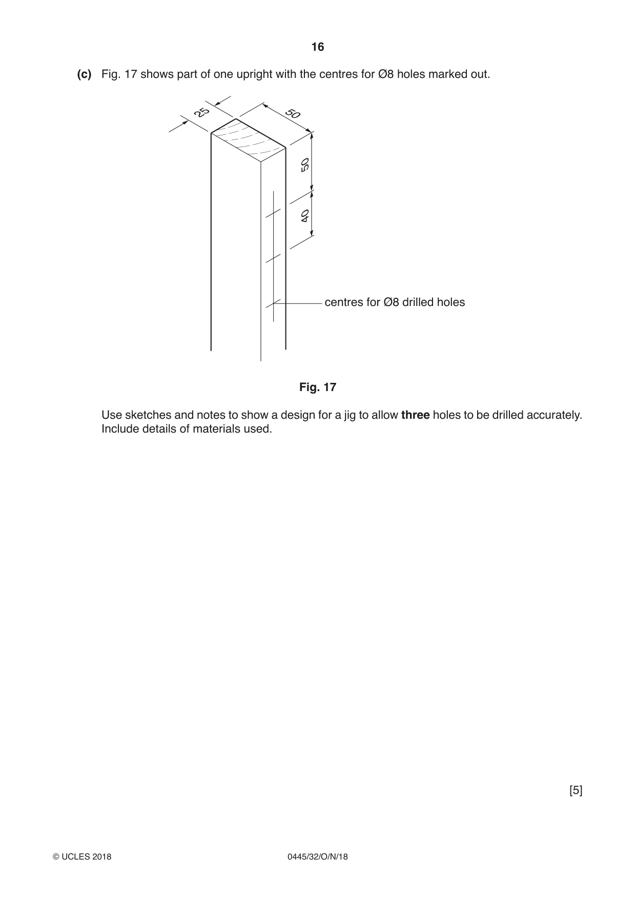
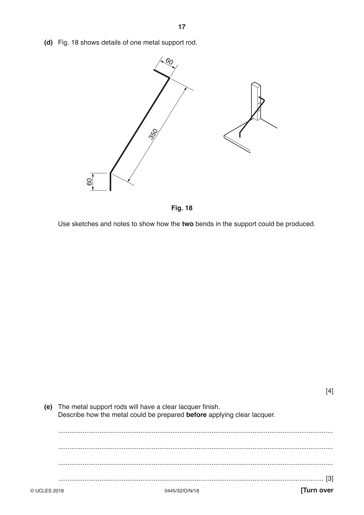
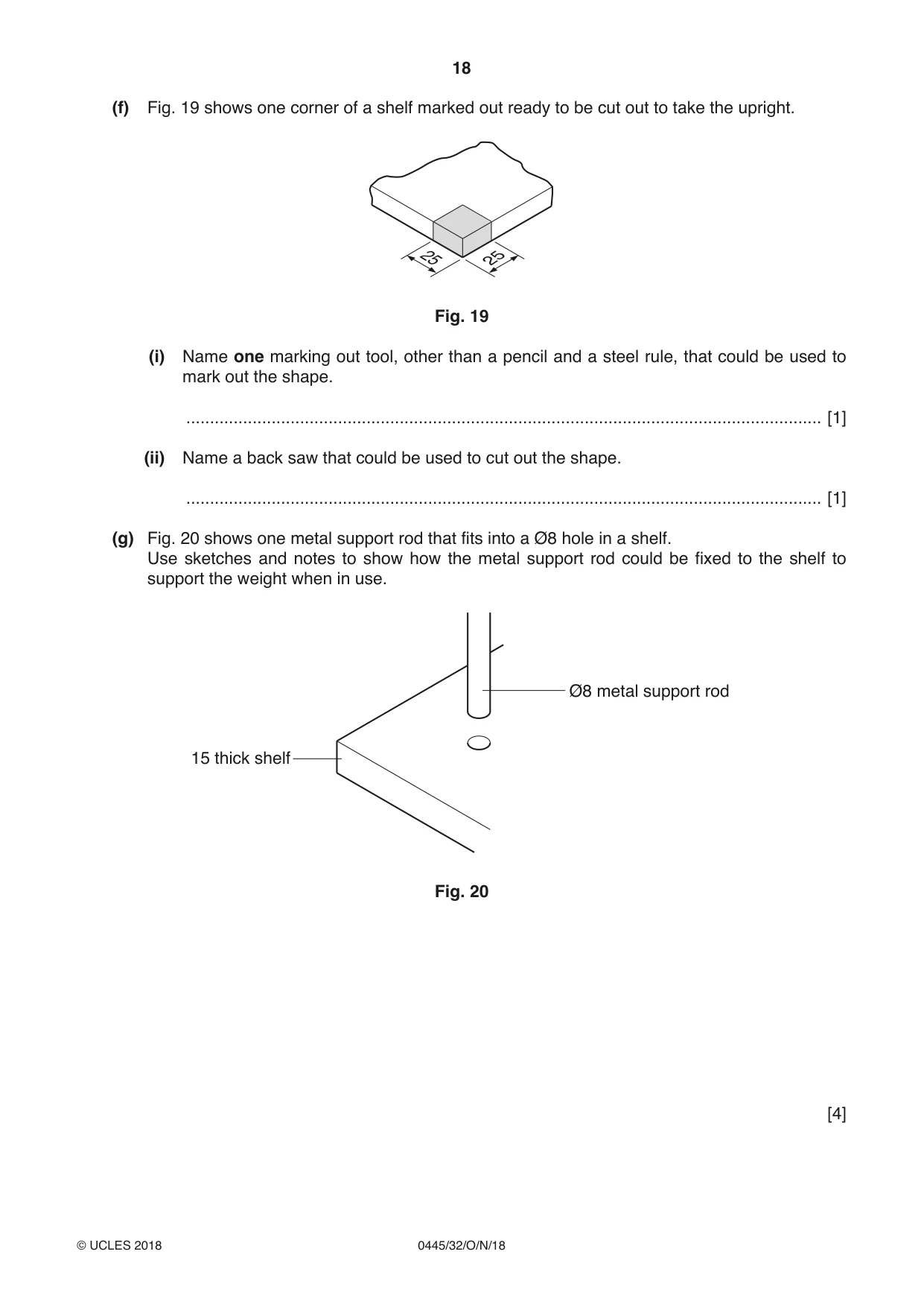
13 Fig. 16 shows a wall-mounted adjustable shelving system. metal support rods Ø8 shelves 700 × 300 × 15 uprights 1200 × 50 × 25 Fig. 16 (a) Name suitable specific materials for the parts of the shelving system: • hardwood uprights ............................................................................................................. • metal support rods ............................................................................................................ • manufactured board shelves ........................................................................................ [3] (b) The manufactured board used for the shelves is veneered. (i) Give one benefit of covering the manufactured board with veneer. ...................................................................................................................................... [1] (ii) Give one drawback of covering the manufactured board with veneer. ...................................................................................................................................... [1] (c) Fig. 17 shows part of one upright with the centres for Ø8 holes marked out. 25 50 50 40 centres for Ø8 drilled holes Fig. 17 Use sketches and notes to show a design for a jig to allow three holes to be drilled accurately. Include details of materials used. [5] (d) Fig. 18 shows details of one metal support rod. 60 350 60 Fig. 18 Use sketches and notes to show how the two bends in the support could be produced. [4] (e) The metal support rods will have a clear lacquer finish. Describe how the metal could be prepared before applying clear lacquer. ................................................................................................................................................... ................................................................................................................................................... ................................................................................................................................................... .............................................................................................................................................. [3]
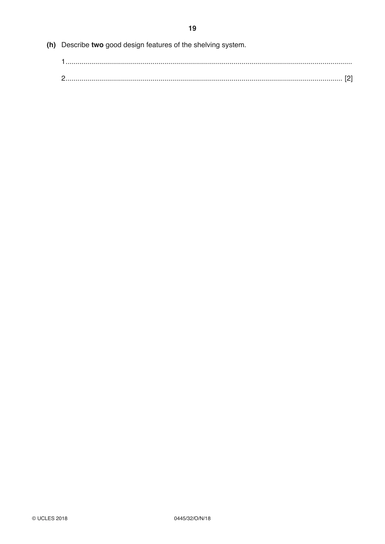
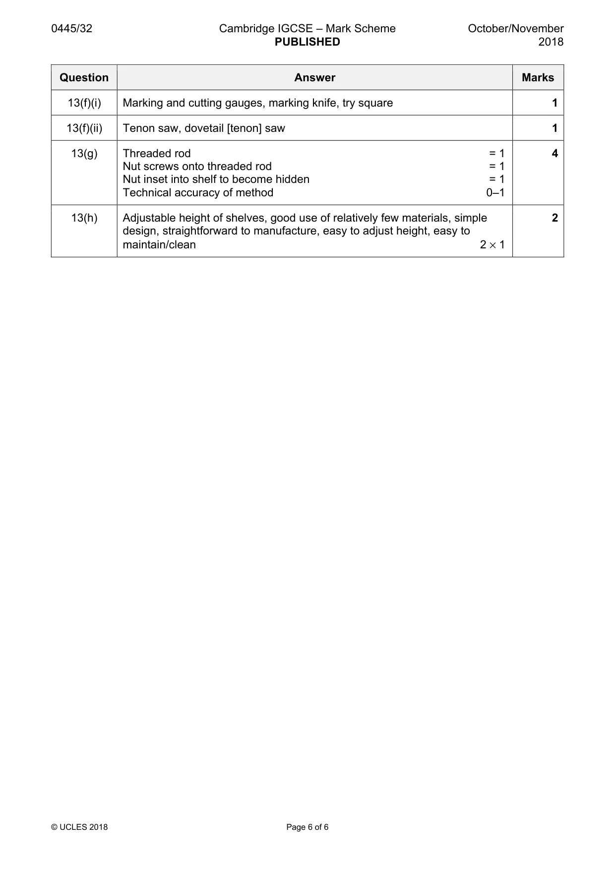
Mark scheme: 13(a) Hardwood uprights: wide variety of suitable hardwoods = 1 3 Metal rod: mild steel, stainless steel, aluminium, brass = 1 Manufactured board: MDF, chipboard, plywood = 1 13(b)(i) Benefit: gives appearance of solid wood, more attractive 1 Drawback: more easily damaged, veneer could peel off, less hardwearing 13(b)(ii) Drawback: more easily damaged, veneer could peel off, less hardwearing 1 13(c) Template with 3 holes drilled-no location = 1 5 Template + 1 side located = 2 Template + 2 sides located = 3 Template + 2 sides + end located = 4 Specific named material/s appropriate = 1 13(d) Use of vice to support the metal rod = 1 4 Method of force: hammer and scrap wood or mallet = 1 Check correct angle of lower bend with former = 1 90° angle checked against vice jaw/wooden former = 1 13(e) Stages include: degrease metal if necessary. 3 Use steel wool [fine grade] or wet and dry [silicon carbide] paper [2 grades]. Use of polishing mop and appropriate compound to produce quality finish. 13(f)(i) Marking and cutting gauges, marking knife, try square 1 13(f)(ii) Tenon saw, dovetail [tenon] saw 1 13(g) Threaded rod = 1 4 Nut screws onto threaded rod = 1 Nut inset into shelf to become hidden = 1 Technical accuracy of method 0–1 13(h) Adjustable height of shelves, good use of relatively few materials, simple 2 design, straightforward to manufacture, easy to adjust height, easy to maintain/clean 2 × 1
What was in this paper
The subtopics covered by these 13 questions, and how many questions each got. Open one in a new tab to see every Cambridge question on it.
What you needed in this session
Cambridge’s own grade thresholds for 2018 Oct/Nov, Paper 3 · Variant 2. A higher threshold means an easier paper — the bar moves with how the cohort did.