Cambridge IGCSE Design and Technology 0445 — 2018 Oct/Nov Paper 3 · Variant 1
0445/31/O/N/18 · 13 questions · 50 marks · ≈56 min
The question paper and its mark scheme, free to read here and free to download. This is Cambridge’s own paper, exactly as it was sat.
Question paper20 pages
Mark scheme10 pages
Answers below. Sit the paper first if you are practising.
Questions as text
Q1 · Name the two standard metal sections shown below
1 Name the two standard metal sections shown below. ......................................... ............................................... [2]
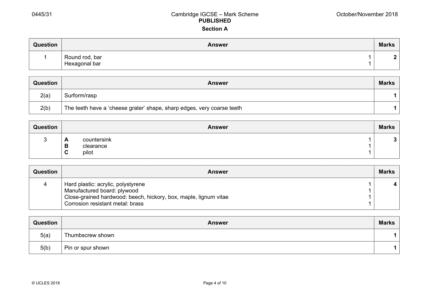
Mark scheme: 1 Round rod, bar 1 Hexagonal bar 1 2
Q2 · Name the type of tools shown in Fig
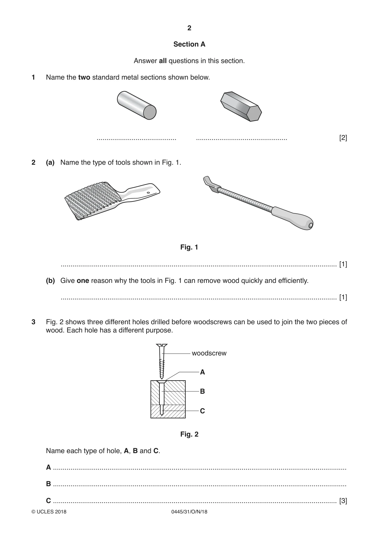
2 (a) Name the type of tools shown in Fig. 1. Fig. 1 .............................................................................................................................................. [1] (b) Give one reason why the tools in Fig. 1 can remove wood quickly and efficiently. .............................................................................................................................................. [1]
Mark scheme: 2(a) Surform/rasp 1 2(b) The teeth have a ‘cheese grater’ shape, sharp edges, very coarse teeth 1
Q3 · Three different holes drilled before woodscrews can be used to join the two pieces of wood
3 Fig. 2 shows three different holes drilled before woodscrews can be used to join the two pieces of wood. Each hole has a different purpose. woodscrew A B C Fig. 2 Name each type of hole, A, B and C. A ....................................................................................................................................................... B ....................................................................................................................................................... C .................................................................................................................................................. [3]
Mark scheme: 3 A countersink 1 B clearance 1 C pilot 1 3
Q4 · Complete the table below by naming a different material that matches each of the…
4 Complete the table below by naming a different material that matches each of the descriptions. Material Description hard plastic, wide range of colours, used to make car rear light clusters manufactured board made by gluing layers together at 90° to each other close-grained hardwood used to make mallet heads and children’s toys an alloy of copper and zinc, metal with corrosion resistance, electrical conductivity [4]
Mark scheme: 4 Hard plastic: acrylic, polystyrene 1 Manufactured board: plywood 1 Close-grained hardwood: beech, hickory, box, maple, lignum vitae 1 Corrosion resistant metal: brass 1 4
Q5 · An incomplete drawing of a marking gauge
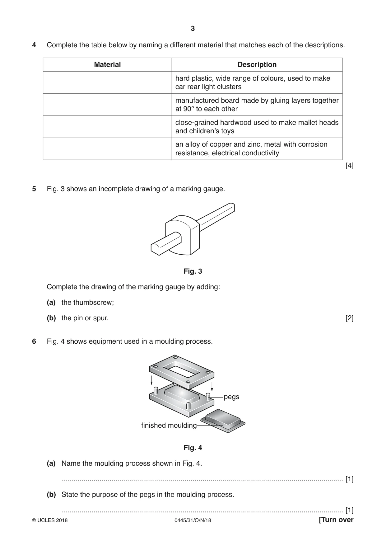
5 Fig. 3 shows an incomplete drawing of a marking gauge. Fig. 3 Complete the drawing of the marking gauge by adding: (a) the thumbscrew; (b) the pin or spur. [2]
Mark scheme: 5(a) Thumbscrew shown 1 5(b) Pin or spur shown 1 Qu uestion Answer Mar rks
Q6 · Equipment used in a moulding process
6 Fig. 4 shows equipment used in a moulding process. pegs finished moulding Fig. 4 (a) Name the moulding process shown in Fig. 4. .............................................................................................................................................. [1] (b) State the purpose of the pegs in the moulding process.
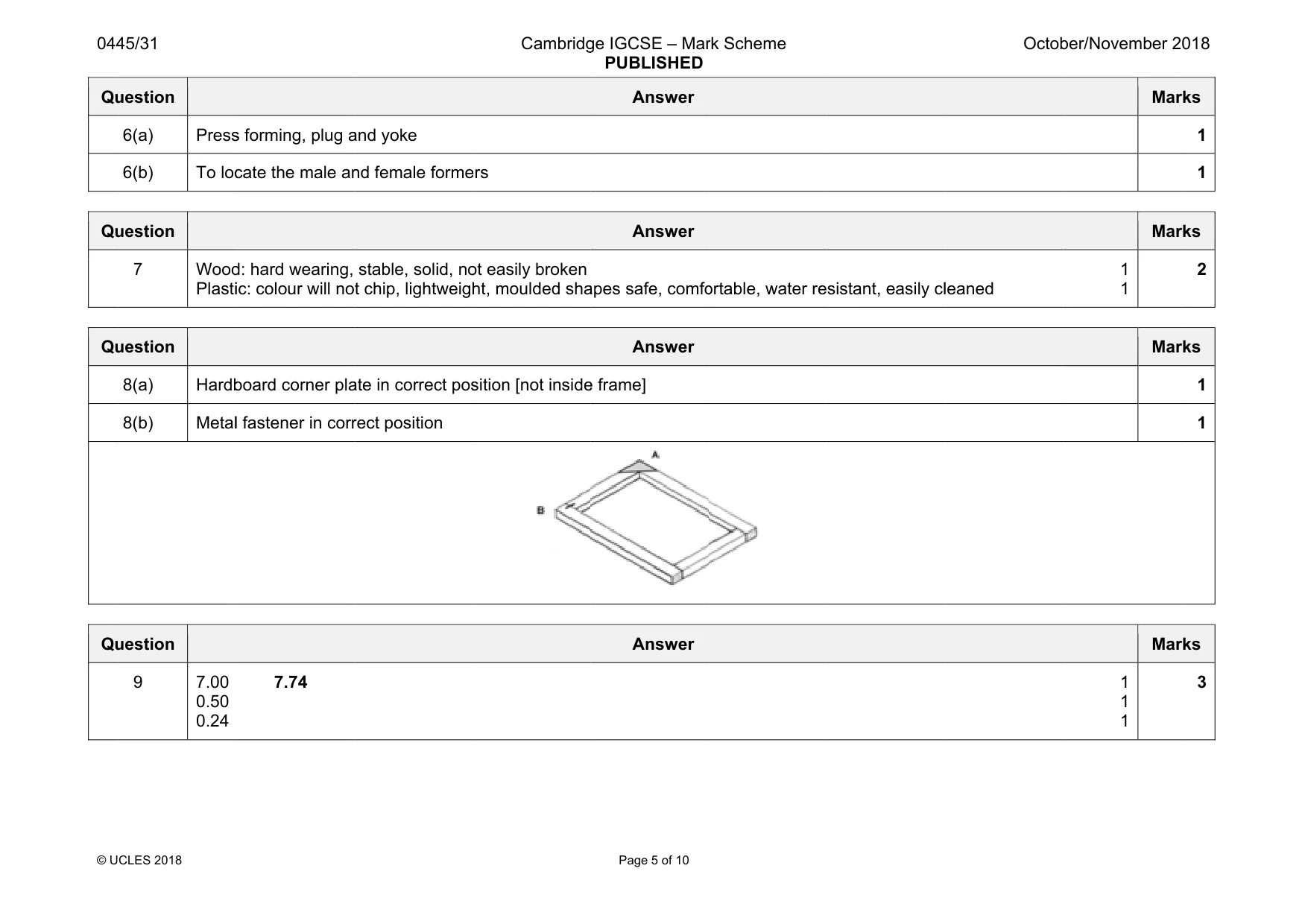
Mark scheme: Qu 6(a) Press 6(b) To loc uestion s forming, plug a cate the male an and yoke nd female forme ers Answer Mar 1 1 rks
Q7 · Two sit-on toys used by children
7 Fig. 5 shows two sit-on toys used by children. Toy A is made from wood and toy B from plastic. A B Fig. 5 Describe one benefit to the user of making a sit-on toy from: wood ................................................................................................................................................. plastic ............................................................................................................................................... [2]
Mark scheme: Qu 7 Wood Plasti uestion d: hard wearing, ic: colour will no stable, solid, no t chip, lightweigh ot easily broken ht, moulded sha apes safe, comfo Answer ortable, water re sistant, easily cl leaned 1 1 Mar 2 rks
Q8 · A wooden frame construction, a hardboard corner plate and a corrugated fastener
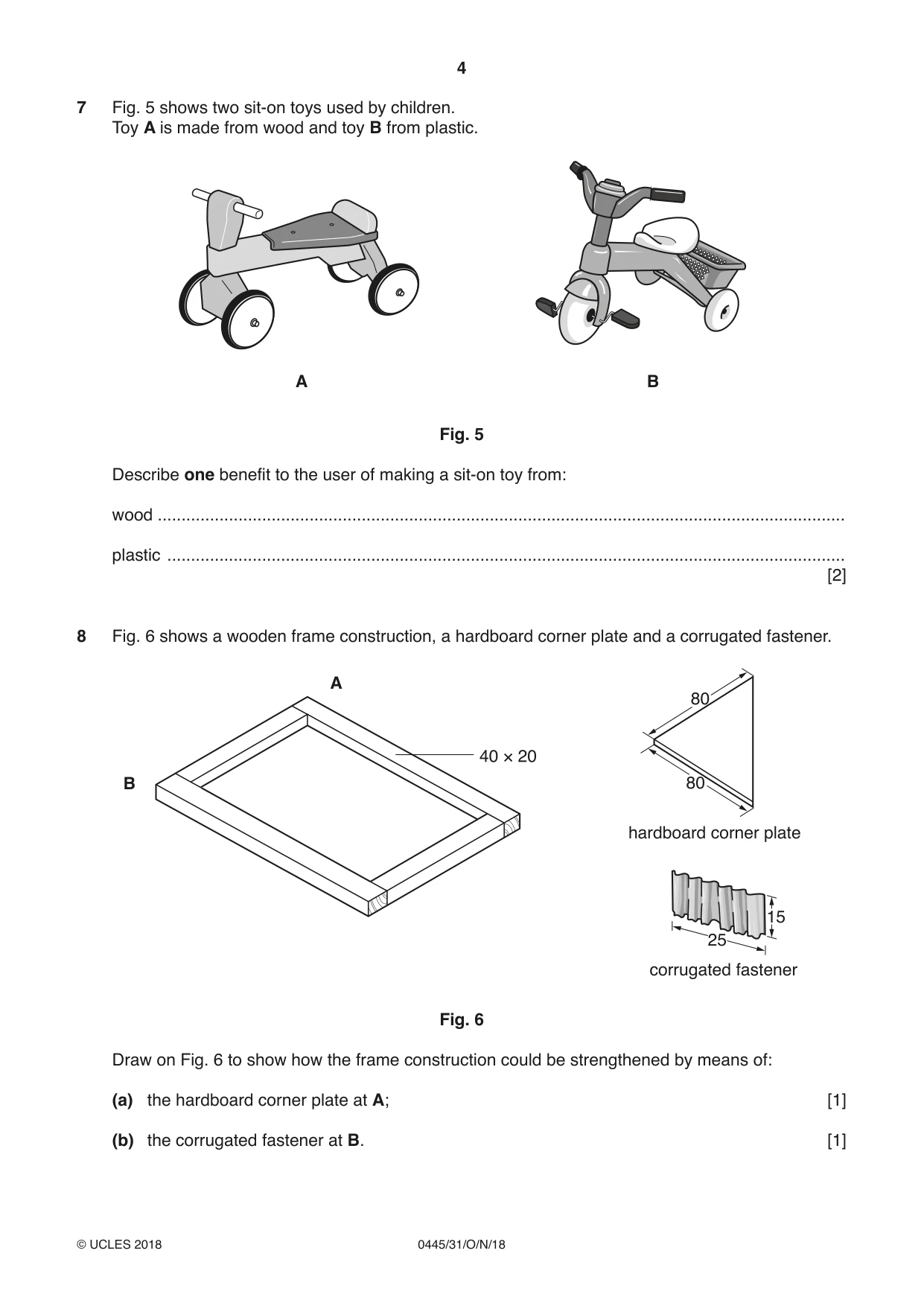
8 Fig. 6 shows a wooden frame construction, a hardboard corner plate and a corrugated fastener. A 80 B 80 hardboard corner plate 15 25 corrugated fastener Fig. 6 Draw on Fig. 6 to show how the frame construction could be strengthened by means of: (a) the hardboard corner plate at A; [1] (b) the corrugated fastener at B. [1]
Mark scheme: Qu 8(a) Hardb 8(b) Metal uestion board corner pla l fastener in corr ate in correct pos rect position sition [not inside e frame] Answer Mar 1 1 rks
Q9 · A metric micrometer and a close-up view of the sleeve and thimble
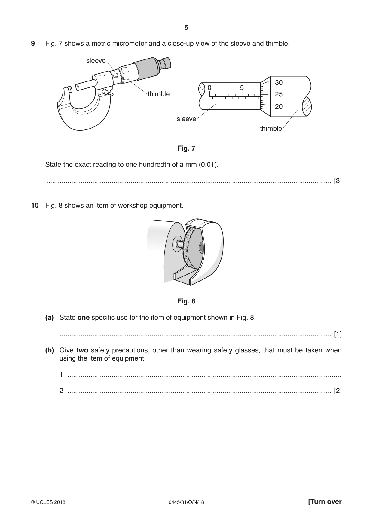
9 Fig. 7 shows a metric micrometer and a close-up view of the sleeve and thimble. sleeve 30 0 5 thimble 25 20 sleeve thimble Fig. 7 State the exact reading to one hundredth of a mm (0.01). ..................................................................................................................................................... [3]
Mark scheme: 9 7.00 0.50 0.24 7.74 1 1 1 3
Q10 · An item of workshop equipment
10 Fig. 8 shows an item of workshop equipment. Fig. 8 (a) State one specific use for the item of equipment shown in Fig. 8. .............................................................................................................................................. [1] (b) Give two safety precautions, other than wearing safety glasses, that must be taken when using the item of equipment. 1 ............................................................................................................................................... 2 .......................................................................................................................................... [2]
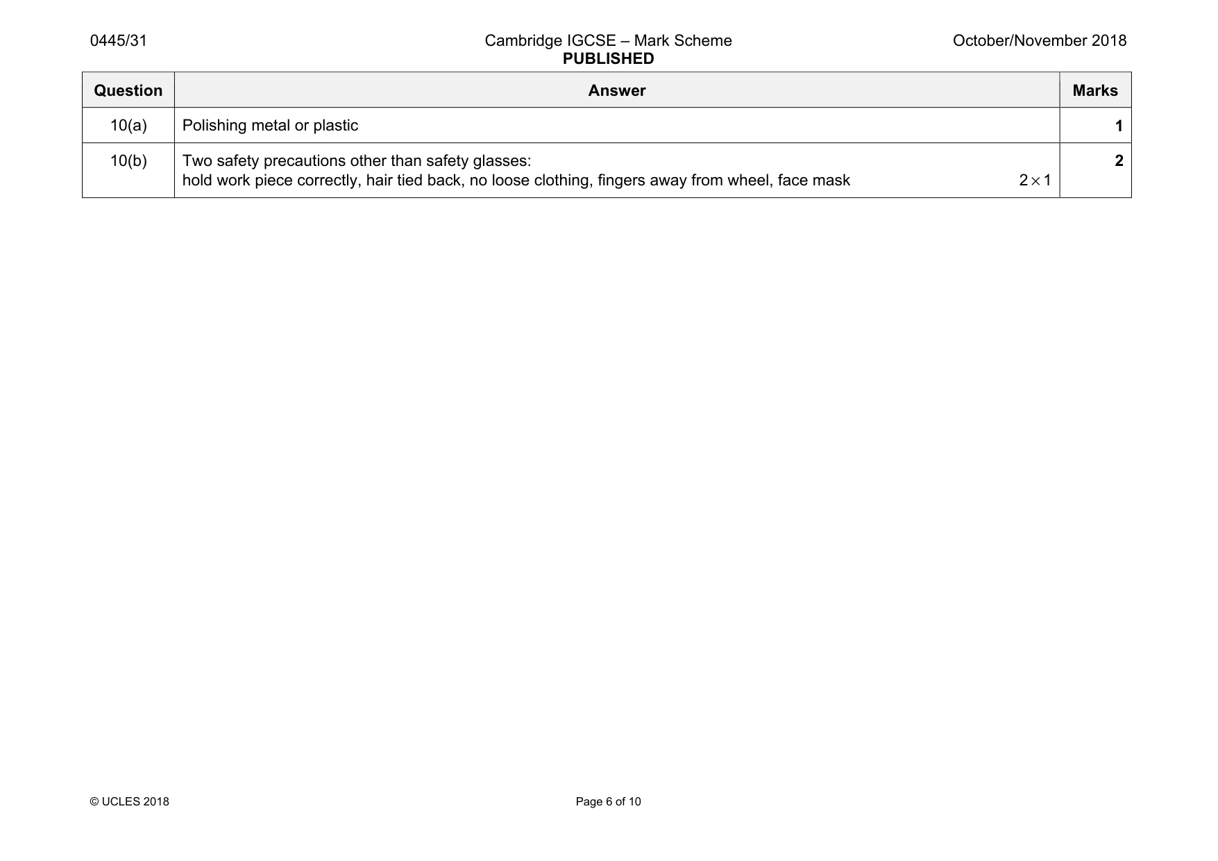
Mark scheme: 10(a) Polishing metal or plastic 1 10(b) Two safety precautions other than safety glasses: hold work piece correctly, hair tied back, no loose clothing, fingers away from wheel, face mask 2 × 1 2
Question 11
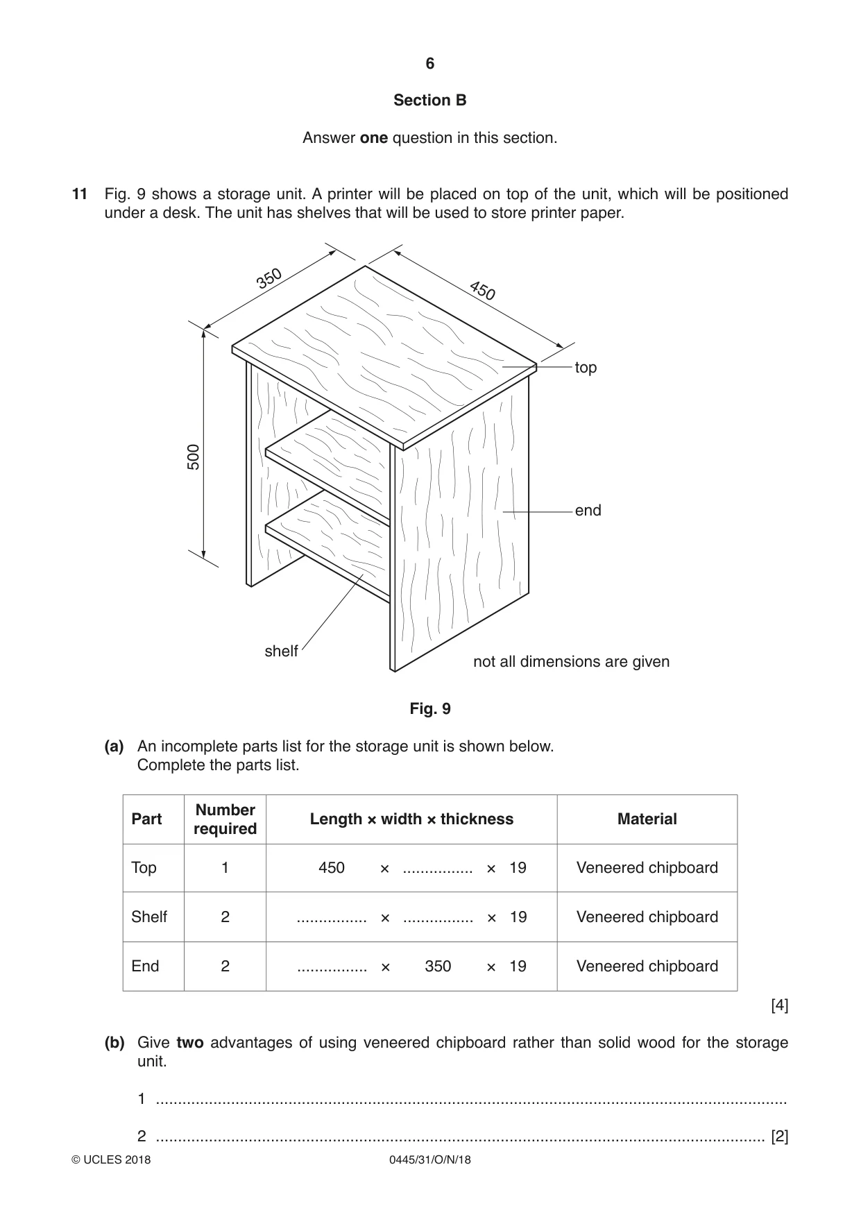
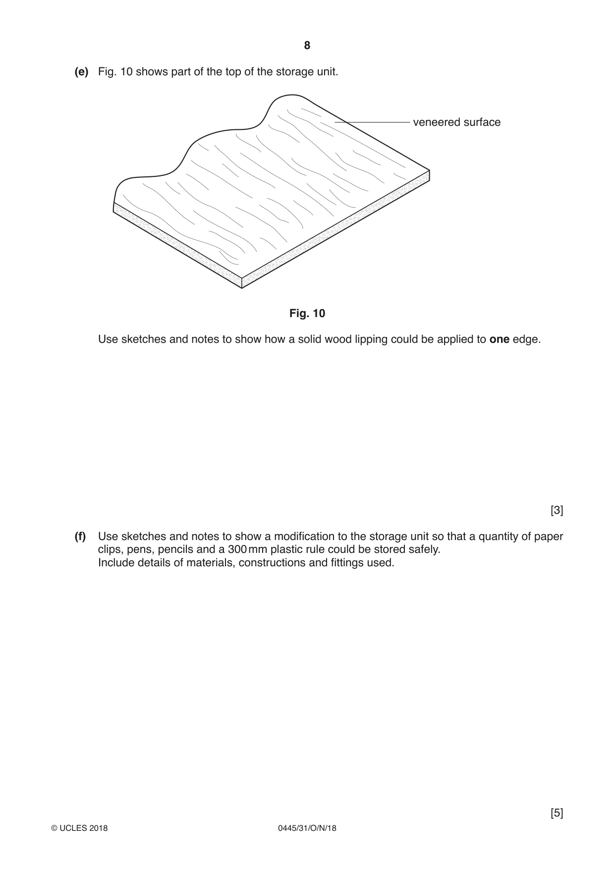
11 Fig. 9 shows a storage unit. A printer will be placed on top of the unit, which will be positioned under a desk. The unit has shelves that will be used to store printer paper. 350 450 top 500 end shelf not all dimensions are given Fig. 9 (a) An incomplete parts list for the storage unit is shown below. Complete the parts list. Number Part Length × width × thickness Material required Top 1 450 × ................ × 19 Veneered chipboard Shelf 2 ................ × ................ × 19 Veneered chipboard End 2 ................ × 350 × 19 Veneered chipboard [4] (b) Give two advantages of using veneered chipboard rather than solid wood for the storage unit. 1 ............................................................................................................................................... 2 .......................................................................................................................................... [2] (c) Sketch and name a pre-manufactured component that would enable the storage unit to be moved about easily. [3] (d) Use sketches and notes to show how one shelf could be joined to one end using knock-down (KD) fittings. [4] (e) Fig. 10 shows part of the top of the storage unit. veneered surface Fig. 10 Use sketches and notes to show how a solid wood lipping could be applied to one edge. [3] (f) Use sketches and notes to show a modification to the storage unit so that a quantity of paper clips, pens, pencils and a 300 mm plastic rule could be stored safely. Include details of materials, constructions and fittings used. [5] (g) There is a possibility that the paper stored on the shelves could fall through the back of the unit. Use sketches and notes to show how this could be prevented. Include details of materials, constructions and fittings used. [4]
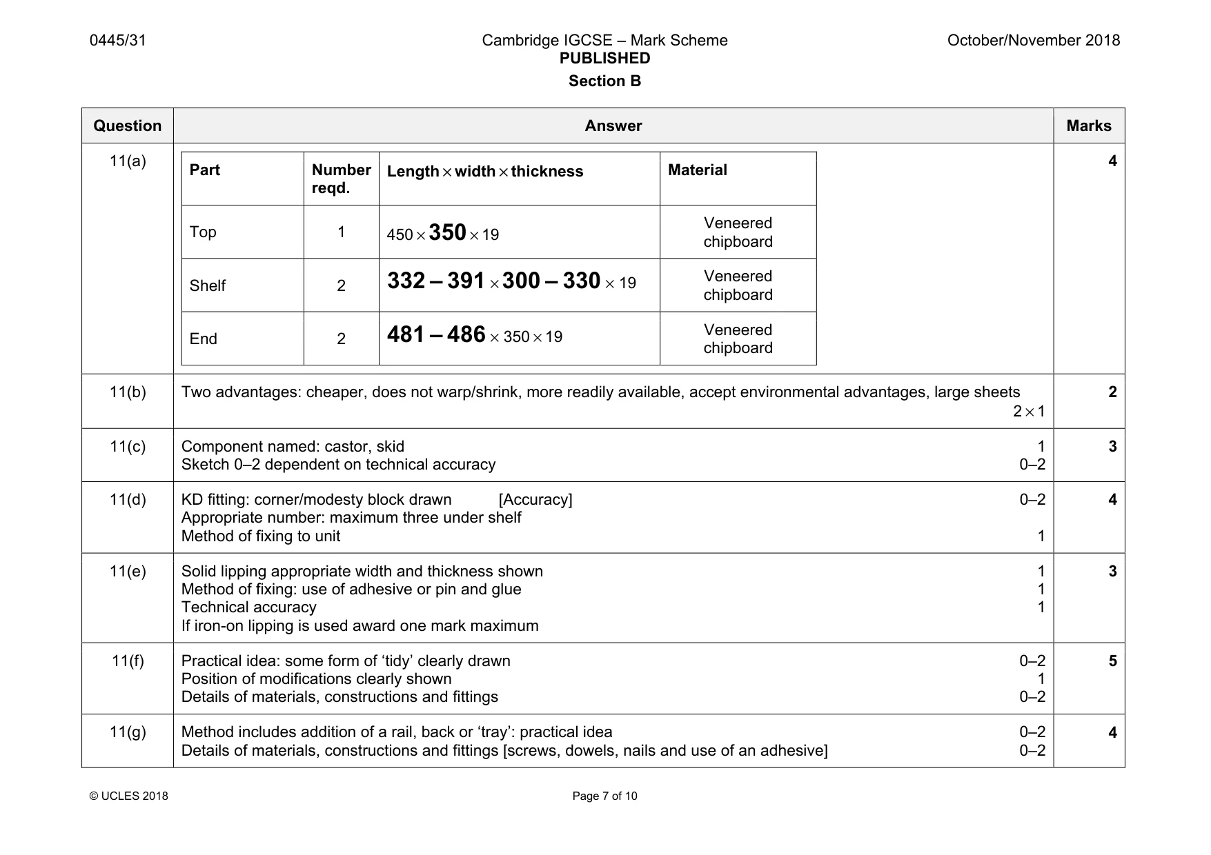
Mark scheme: 11(a) Part Number reqd. Length × width × thickness Material Top 1 450 × 350 × 19 Veneered chipboard Shelf 2 332 – 391 × 300 – 330 × 19 Veneered chipboard End 2 481 – 486 × 350 × 19 Veneered chipboard 4 11(b) Two advantages: cheaper, does not warp/shrink, more readily available, accept environmental advantages, large sheets 2 × 1 2 11(c) Component named: castor, skid 1 Sketch 0–2 dependent on technical accuracy 0–2 3 11(d) KD fitting: corner/modesty block drawn [Accuracy] 0–2 Appropriate number: maximum three under shelf Method of fixing to unit 1 4 11(e) Solid lipping appropriate width and thickness shown 1 Method of fixing: use of adhesive or pin and glue 1 Technical accuracy 1 If iron-on lipping is used award one mark maximum 3 11(f) Practical idea: some form of ‘tidy’ clearly drawn 0–2 Position of modifications clearly shown 1 Details of materials, constructions and fittings 0–2 5 11(g) Method includes addition of a rail, back or ‘tray’: practical idea 0–2 Details of materials, constructions and fittings [screws, dowels, nails and use of an adhesive] 0–2 4
Q12 · A headphone stand made from 5 thick acrylic
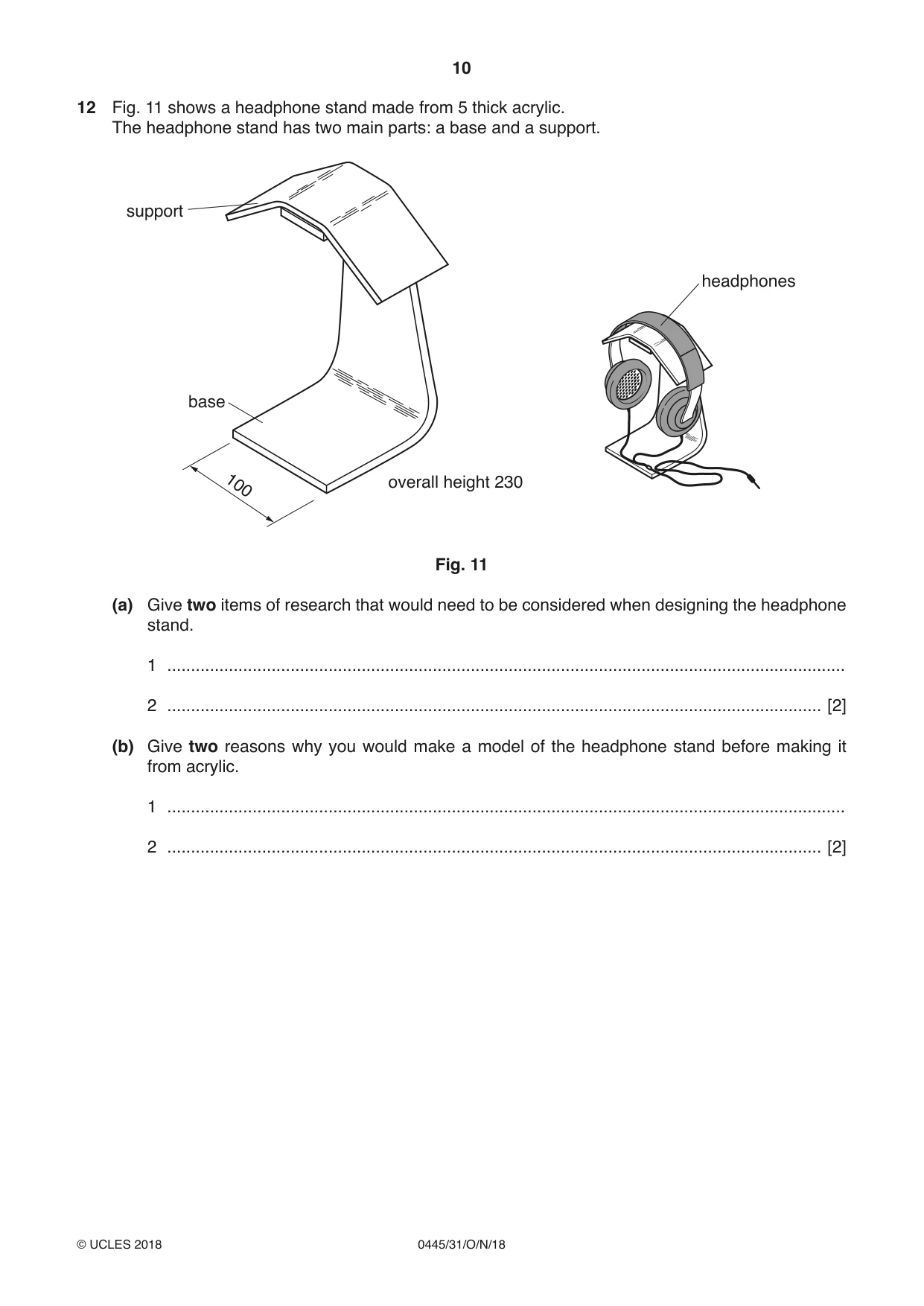
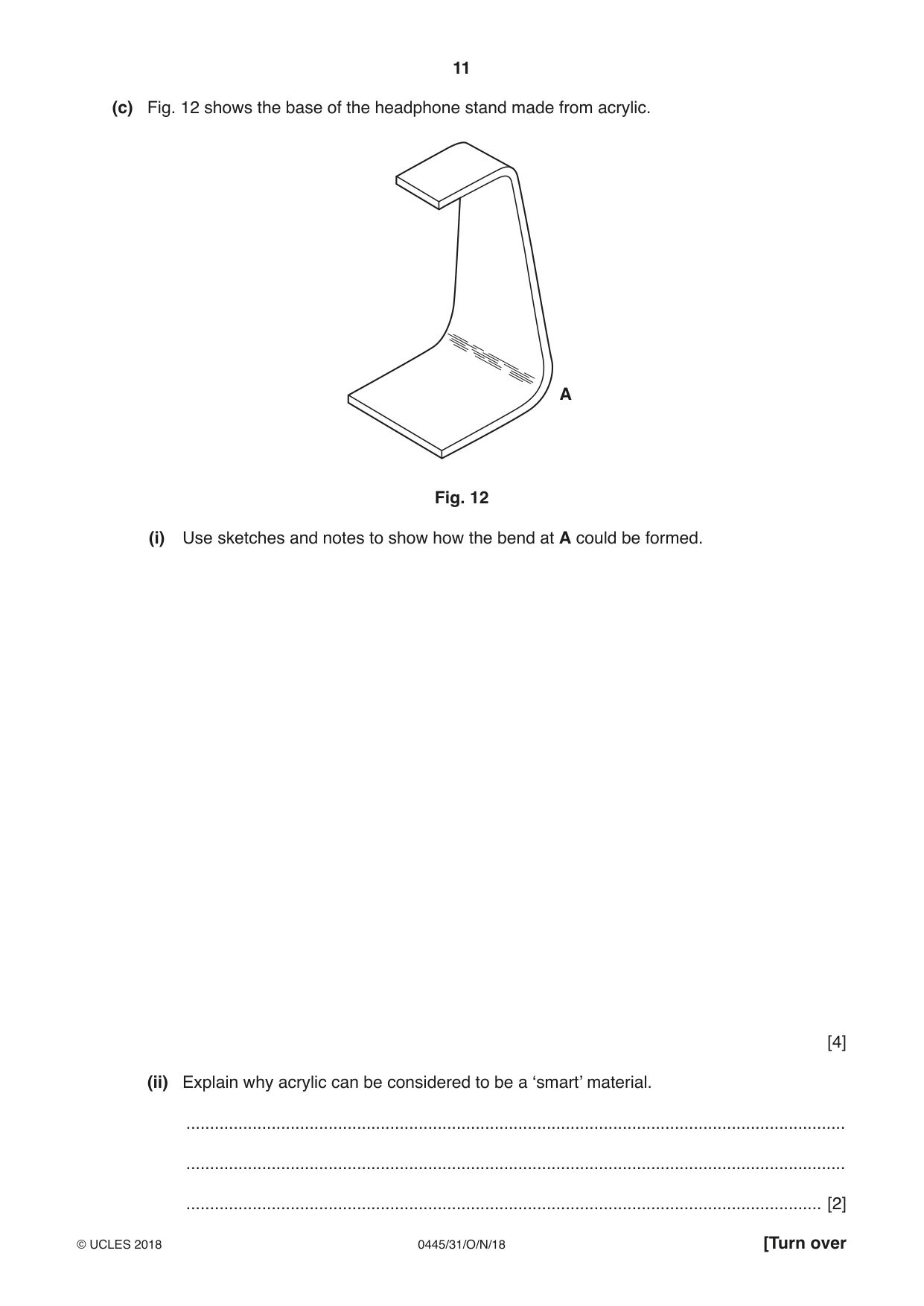
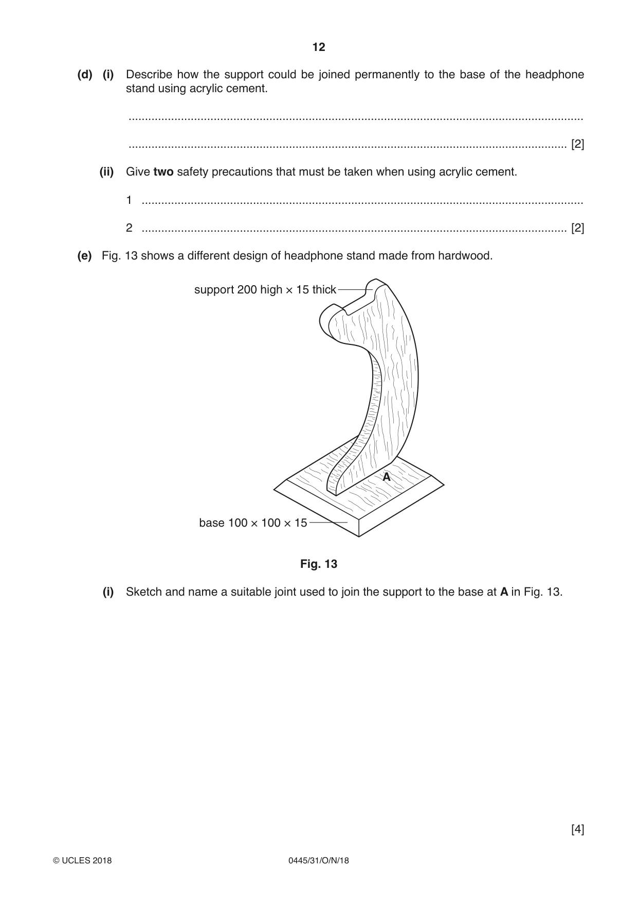
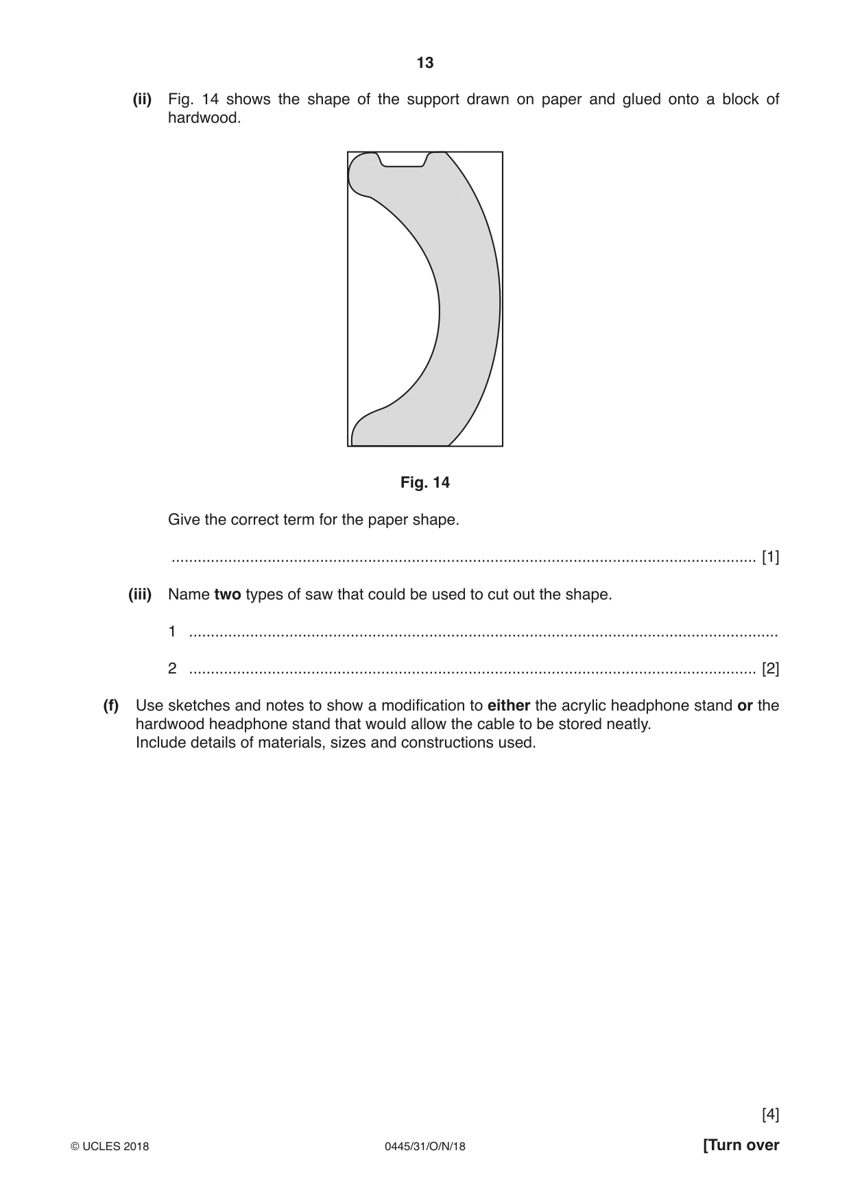
12 Fig. 11 shows a headphone stand made from 5 thick acrylic. The headphone stand has two main parts: a base and a support. support headphones base 100 overall height 230 Fig. 11 (a) Give two items of research that would need to be considered when designing the headphone stand. 1 ............................................................................................................................................... 2 .......................................................................................................................................... [2] (b) Give two reasons why you would make a model of the headphone stand before making it from acrylic. 1 ............................................................................................................................................... 2 .......................................................................................................................................... [2] (c) Fig. 12 shows the base of the headphone stand made from acrylic. A Fig. 12 (i) Use sketches and notes to show how the bend at A could be formed. [4] (ii) Explain why acrylic can be considered to be a ‘smart’ material. ........................................................................................................................................... ........................................................................................................................................... ...................................................................................................................................... [2] (d) (i) Describe how the support could be joined permanently to the base of the headphone stand using acrylic cement. ........................................................................................................................................... ...................................................................................................................................... [2] (ii) Give two safety precautions that must be taken when using acrylic cement. 1 ....................................................................................................................................... 2 .................................................................................................................................. [2] (e) Fig. 13 shows a different design of headphone stand made from hardwood. support 200 high × 15 thick A base 100 × 100 × 15 Fig. 13 (i) Sketch and name a suitable joint used to join the support to the base at A in Fig. 13. [4] (ii) Fig. 14 shows the shape of the support drawn on paper and glued onto a block of hardwood. Fig. 14 Give the correct term for the paper shape. ...................................................................................................................................... [1] (iii) Name two types of saw that could be used to cut out the shape. 1 ....................................................................................................................................... 2 .................................................................................................................................. [2] (f) Use sketches and notes to show a modification to either the acrylic headphone stand or the hardwood headphone stand that would allow the cable to be stored neatly. Include details of materials, sizes and constructions used. [4]
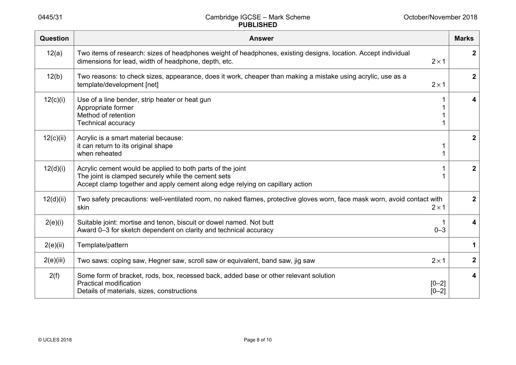
Mark scheme: 12(a) Two items of research: sizes of headphones weight of headphones, existing designs, location. Accept individual dimensions for lead, width of headphone, depth, etc. 2 × 1 2 12(b) Two reasons: to check sizes, appearance, does it work, cheaper than making a mistake using acrylic, use as a template/development [net] 2 × 1 2 12(c)(i) Use of a line bender, strip heater or heat gun 1 Appropriate former 1 Method of retention 1 Technical accuracy 1 4 12(c)(ii) Acrylic is a smart material because: it can return to its original shape 1 when reheated 1 2 12(d)(i) Acrylic cement would be applied to both parts of the joint 1 The joint is clamped securely while the cement sets 1 Accept clamp together and apply cement along edge relying on capillary action 2 12(d)(ii) Two safety precautions: well-ventilated room, no naked flames, protective gloves worn, face mask worn, avoid contact with skin 2 × 1 2 2(e)(i) Suitable joint: mortise and tenon, biscuit or dowel named. Not butt 1 Award 0–3 for sketch dependent on clarity and technical accuracy 0–3 4 2(e)(ii) Template/pattern 1 2(e)(iii) Two saws: coping saw, Hegner saw, scroll saw or equivalent, band saw, jig saw 2 × 1 2 2(f) Some form of bracket, rods, box, recessed back, added base or other relevant solution Practical modification [0–2] Details of materials, sizes, constructions [0–2] 4
Q13 · Two designs of shelf units
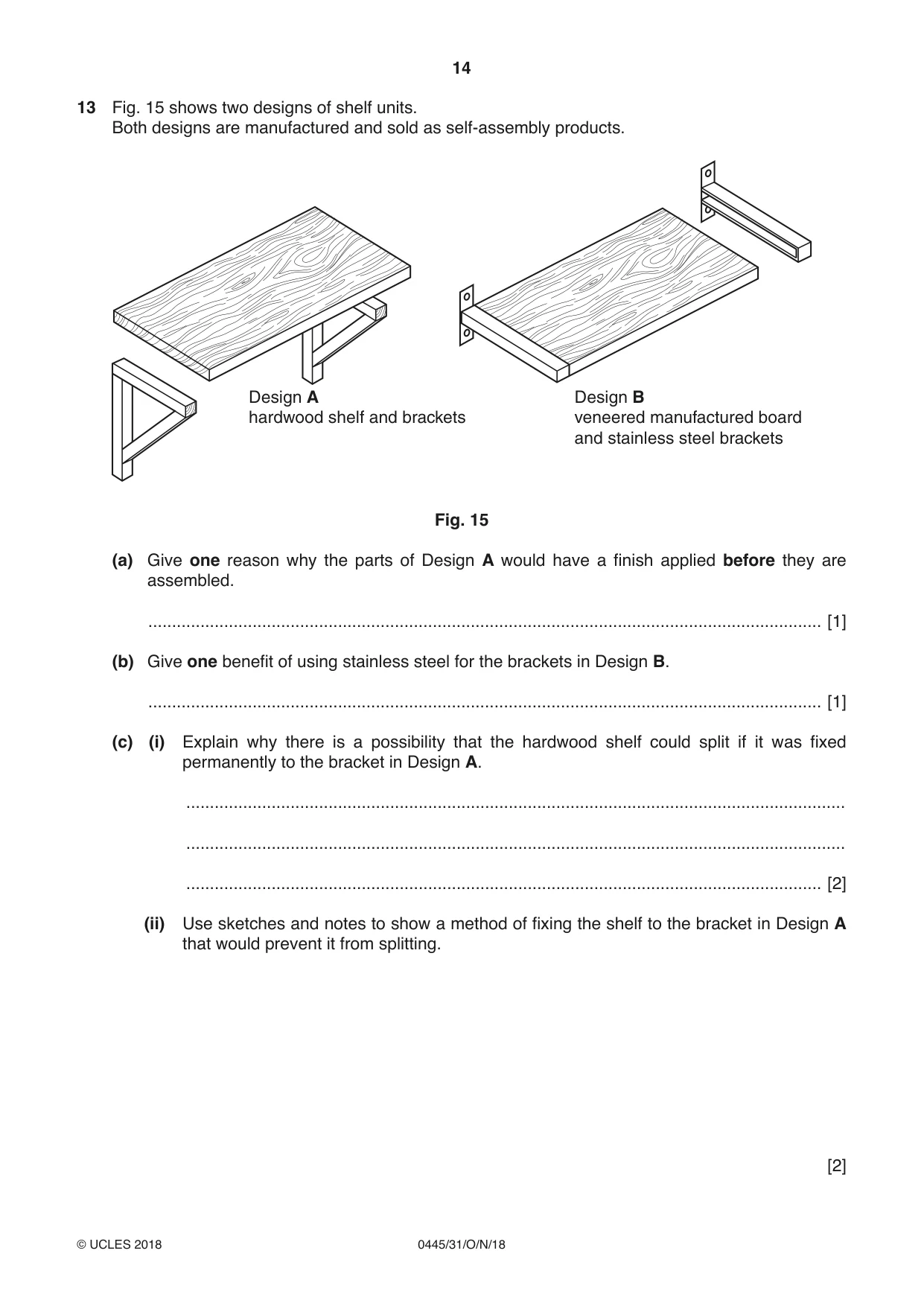
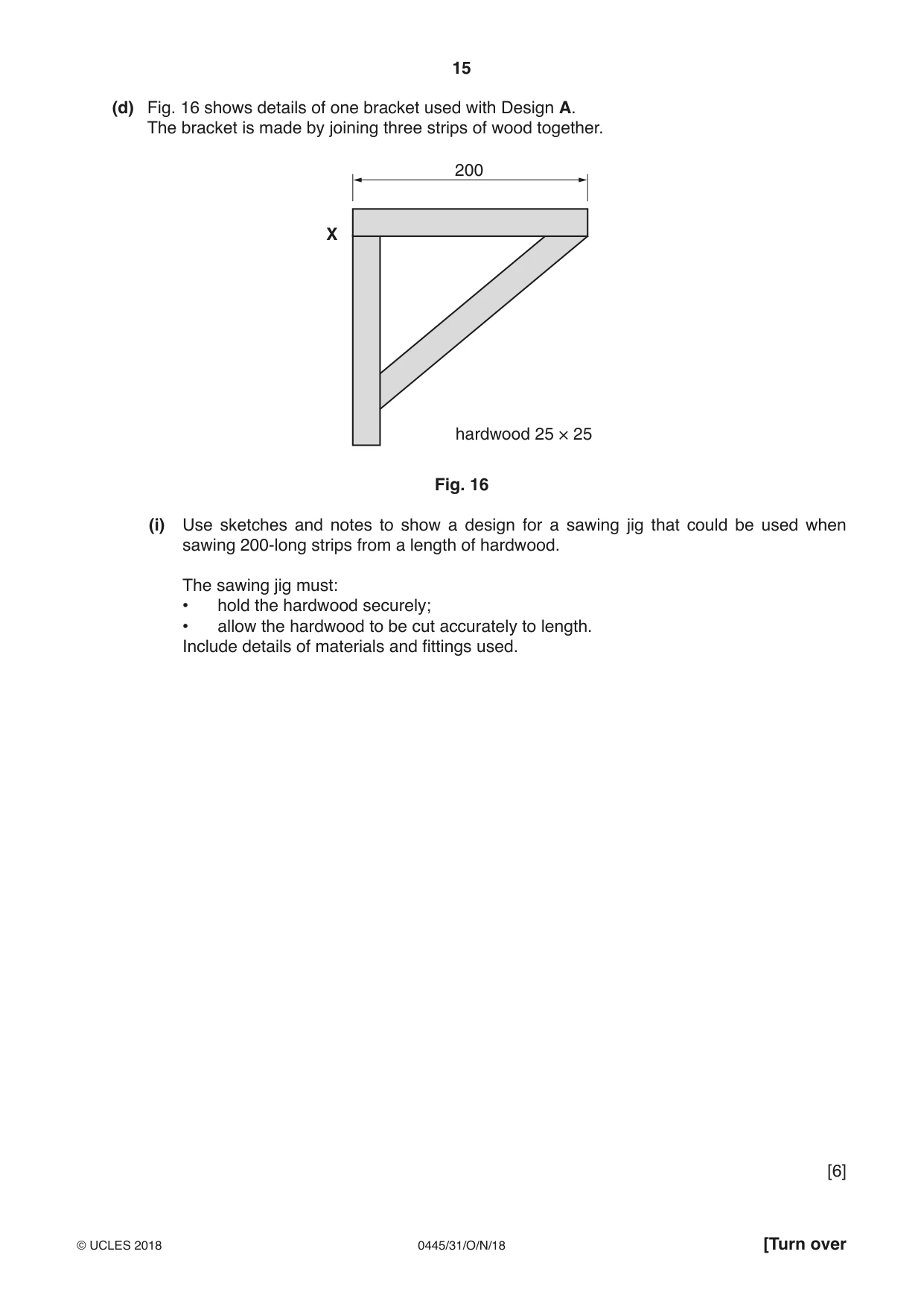
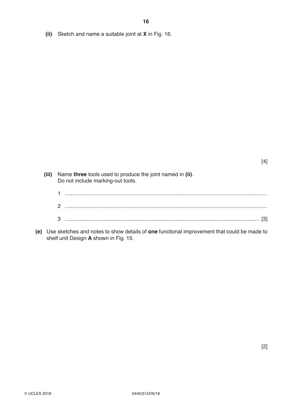
13 Fig. 15 shows two designs of shelf units. Both designs are manufactured and sold as self-assembly products. Design A Design B hardwood shelf and brackets veneered manufactured board and stainless steel brackets Fig. 15 (a) Give one reason why the parts of Design A would have a finish applied before they are assembled. .............................................................................................................................................. [1] (b) Give one benefit of using stainless steel for the brackets in Design B. .............................................................................................................................................. [1] (c) (i) Explain why there is a possibility that the hardwood shelf could split if it was fixed permanently to the bracket in Design A. ........................................................................................................................................... ........................................................................................................................................... ...................................................................................................................................... [2] (ii) Use sketches and notes to show a method of fixing the shelf to the bracket in Design A that would prevent it from splitting. [2] (d) Fig. 16 shows details of one bracket used with Design A. The bracket is made by joining three strips of wood together. 200 X hardwood 25 × 25 Fig. 16 (i) Use sketches and notes to show a design for a sawing jig that could be used when sawing 200-long strips from a length of hardwood. The sawing jig must: • hold the hardwood securely; • allow the hardwood to be cut accurately to length. Include details of materials and fittings used. [6] (ii) Sketch and name a suitable joint at X in Fig. 16. [4] (iii) Name three tools used to produce the joint named in (ii). Do not include marking-out tools. 1 ....................................................................................................................................... 2 ....................................................................................................................................... 3 .................................................................................................................................. [3] (e) Use sketches and notes to show details of one functional improvement that could be made to shelf unit Design A shown in Fig. 15. [2]
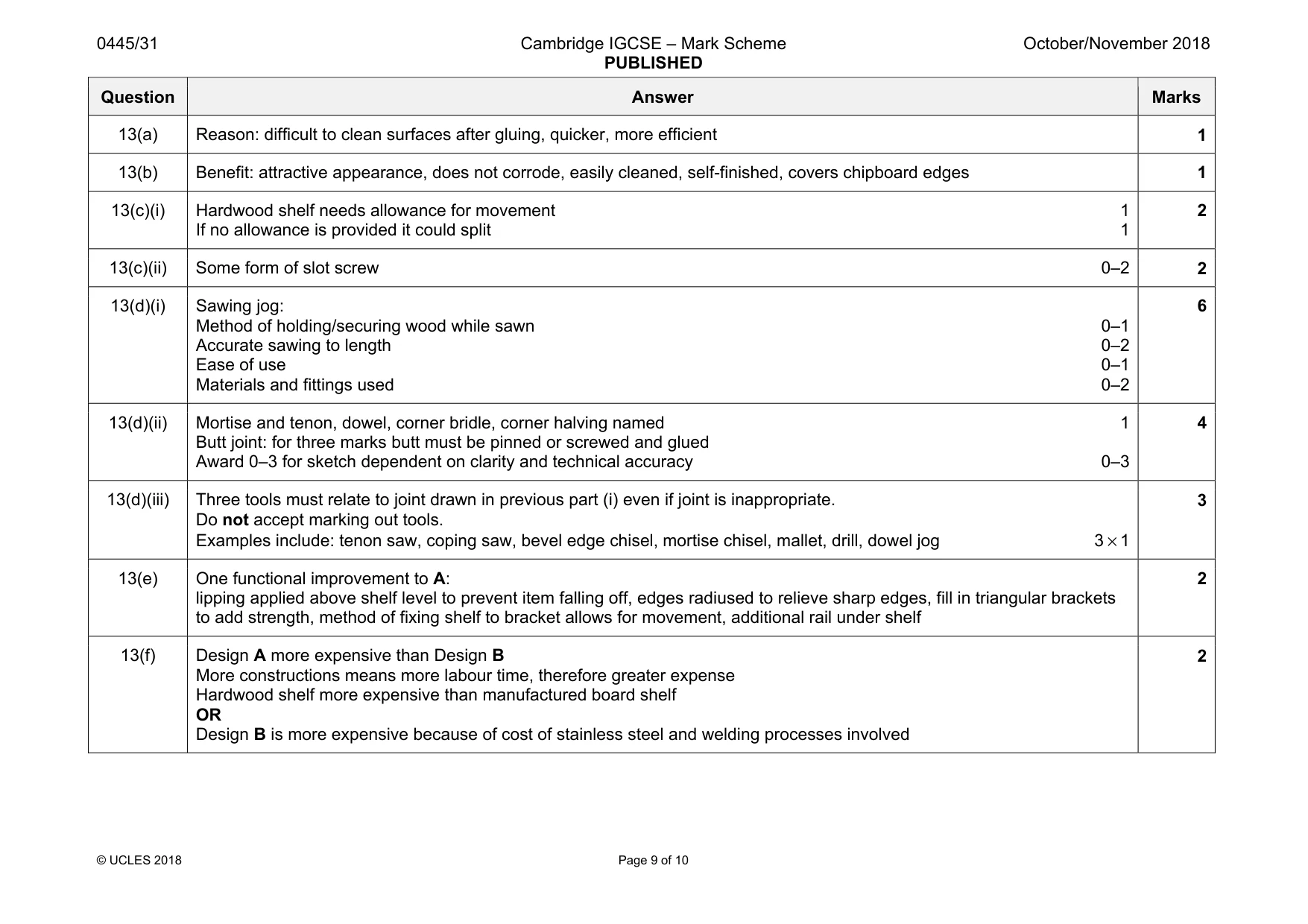
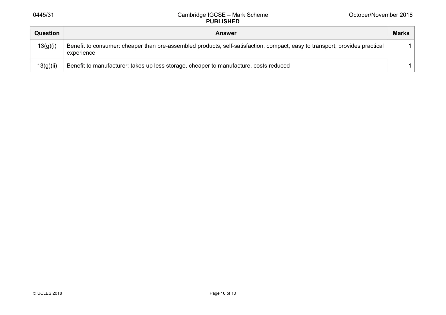
Mark scheme: 13(a) Reason: difficult to clean surfaces after gluing, quicker, more efficient 1 13(b) Benefit: attractive appearance, does not corrode, easily cleaned, self-finished, covers chipboard edges 1 13(c)(i) Hardwood shelf needs allowance for movement 1 If no allowance is provided it could split 1 2 13(c)(ii) Some form of slot screw 0–2 2 13(d)(i) Sawing jog: Method of holding/securing wood while sawn 0–1 Accurate sawing to length 0–2 Ease of use 0–1 Materials and fittings used 0–2 6 13(d)(ii) Mortise and tenon, dowel, corner bridle, corner halving named 1 Butt joint: for three marks butt must be pinned or screwed and glued Award 0–3 for sketch dependent on clarity and technical accuracy 0–3 4 13(d)(iii) Three tools must relate to joint drawn in previous part (i) even if joint is inappropriate. Do not accept marking out tools. Examples include: tenon saw, coping saw, bevel edge chisel, mortise chisel, mallet, drill, dowel jog 3 × 1 3 13(e) One functional improvement to A: lipping applied above shelf level to prevent item falling off, edges radiused to relieve sharp edges, fill in triangular brackets to add strength, method of fixing shelf to bracket allows for movement, additional rail under shelf 2 13(f) Design A more expensive than Design B More constructions means more labour time, therefore greater expense Hardwood shelf more expensive than manufactured board shelf OR Design B is more expensive because of cost of stainless steel and welding processes involved 2 Question Answer Marks 13(g)(i) Benefit to consumer: cheaper than pre-assembled products, self-satisfaction, compact, easy to transport, provides practical experience 1 13(g)(ii) Benefit to manufacturer: takes up less storage, cheaper to manufacture, costs reduced 1
What was in this paper
The subtopics covered by these 13 questions, and how many questions each got. Open one in a new tab to see every Cambridge question on it.
What you needed in this session
Cambridge’s own grade thresholds for 2018 Oct/Nov, Paper 3 · Variant 1. A higher threshold means an easier paper — the bar moves with how the cohort did.