Cambridge IGCSE Design and Technology 0445 — 2017 May/June Paper 3 · Variant 2
0445/32/M/J/17 · 13 questions · 50 marks · ≈56 min
The question paper and its mark scheme, free to read here and free to download. This is Cambridge’s own paper, exactly as it was sat.
Question paper16 pages
Mark scheme6 pages
Answers below. Sit the paper first if you are practising.
Questions as text
Q1 · Two pieces of hardwood that have been glued together
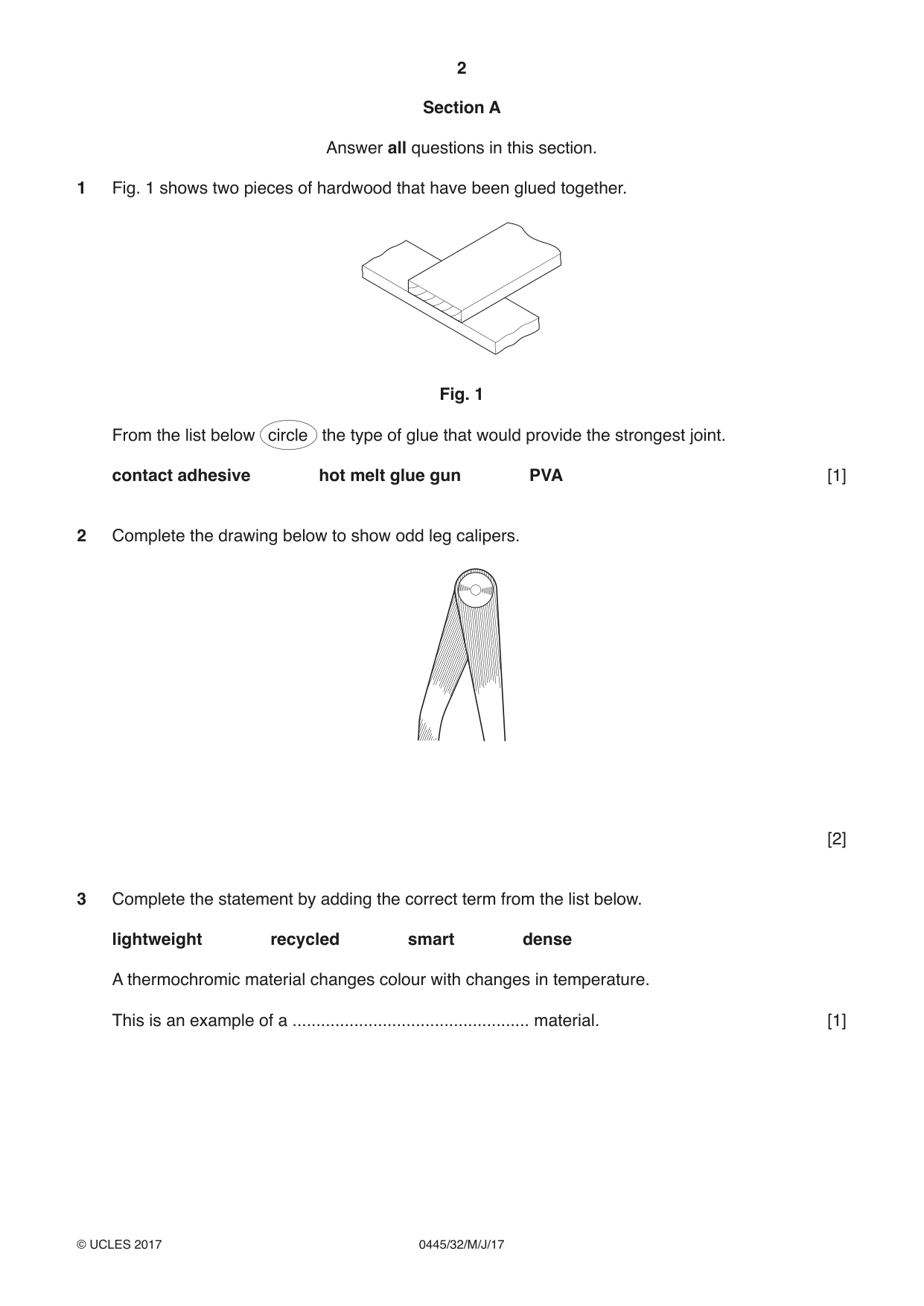
1 Fig. 1 shows two pieces of hardwood that have been glued together. Fig. 1 From the list below circle the type of glue that would provide the strongest joint. contact adhesive hot melt glue gun PVA [1]
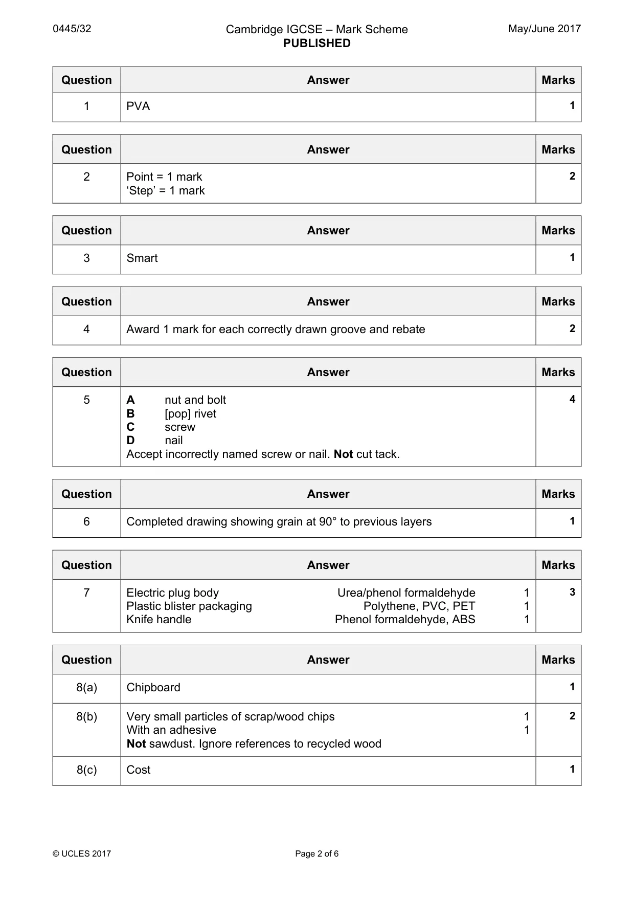
Mark scheme: Question Answer Marks 1 PVA 1
Q2 · Complete the drawing below to show odd leg calipers
2 Complete the drawing below to show odd leg calipers. [2]
Mark scheme: 2 Point = 1 mark 2 ‘Step’ = 1 mark
Q3 · Complete the statement by adding the correct term from the list below
3 Complete the statement by adding the correct term from the list below. lightweight recycled smart dense A thermochromic material changes colour with changes in temperature. This is an example of a .................................................. material. [1]
Mark scheme: 3 Smart 1
Q4 · The end of a length of wood
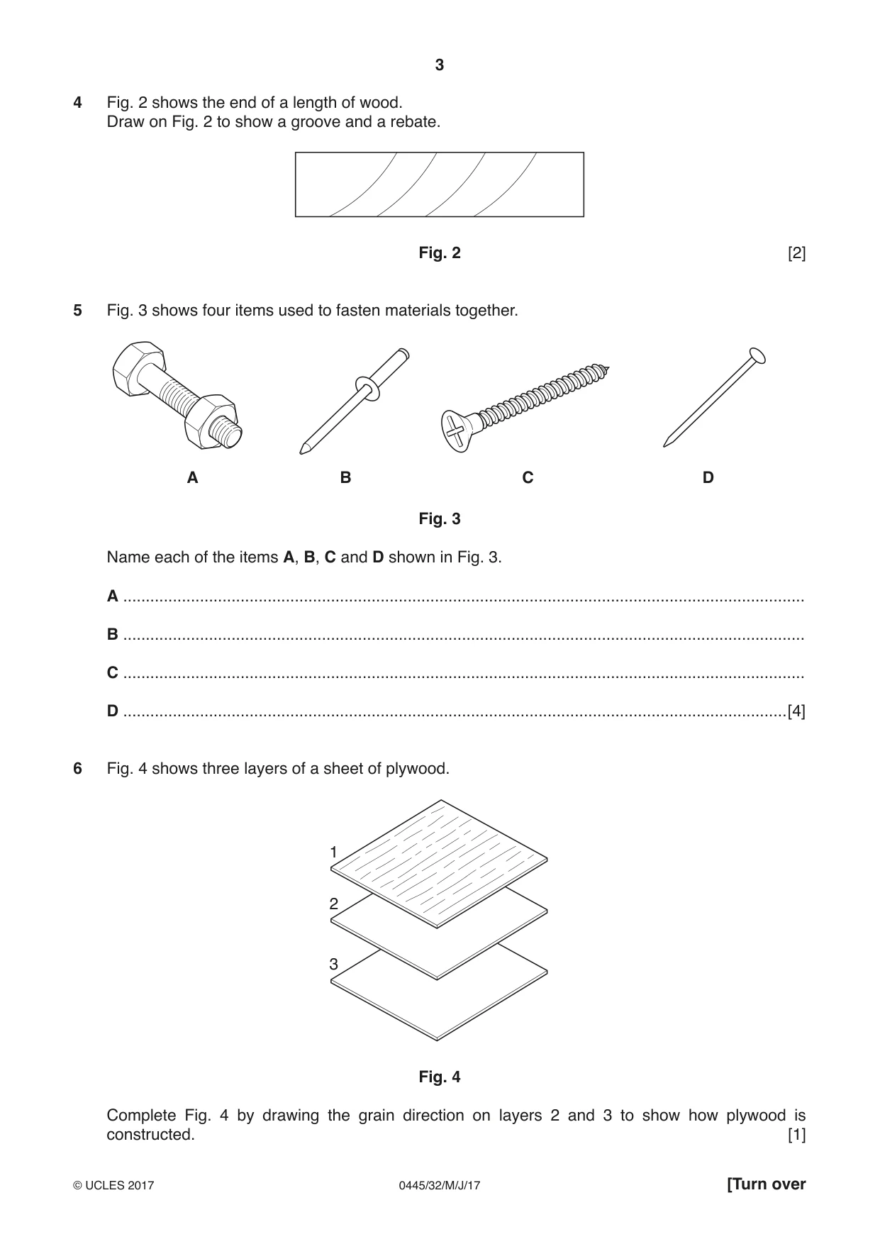
4 Fig. 2 shows the end of a length of wood. Draw on Fig. 2 to show a groove and a rebate. Fig. 2 [2]
Mark scheme: 4 Award 1 mark for each correctly drawn groove and rebate 2
Q5 · Four items used to fasten materials together
5 Fig. 3 shows four items used to fasten materials together. A B C D Fig. 3 Name each of the items A, B, C and D shown in Fig. 3. A ....................................................................................................................................................... B ....................................................................................................................................................... C ....................................................................................................................................................... D ...................................................................................................................................................[4]
Mark scheme: 5 A nut and bolt 4 B [pop] rivet C screw D nail Accept incorrectly named screw or nail. Not cut tack.
Q6 · Three layers of a sheet of plywood
6 Fig. 4 shows three layers of a sheet of plywood. 1 2 3 Fig. 4 Complete Fig. 4 by drawing the grain direction on layers 2 and 3 to show how plywood is constructed. [1]
Mark scheme: 6 Completed drawing showing grain at 90° to previous layers 1
Q7 · The table below shows products made mainly from plastic
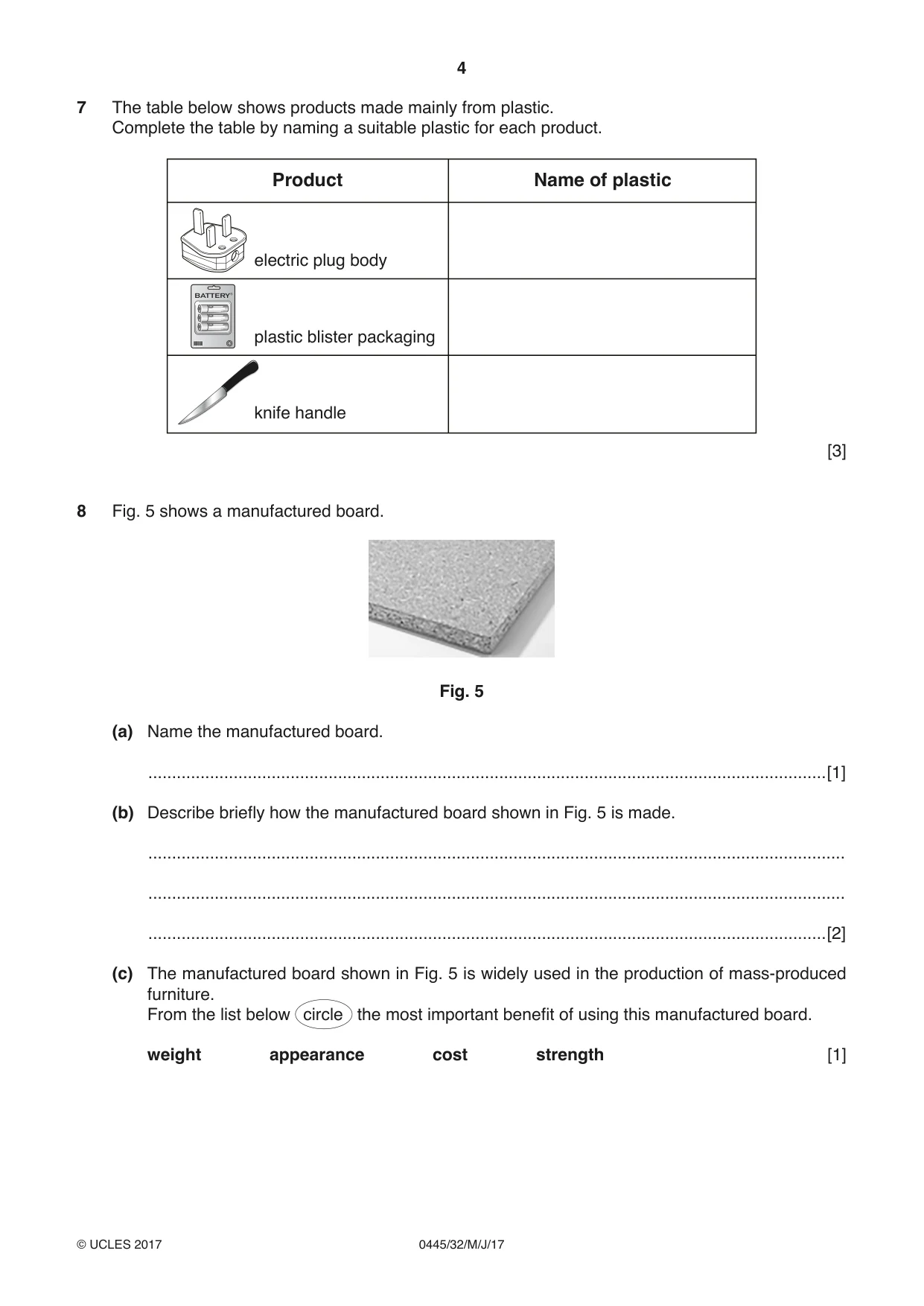
7 The table below shows products made mainly from plastic. Complete the table by naming a suitable plastic for each product. Product Name of plastic electric plug body BATTERY plastic blister packaging knife handle [3]
Mark scheme: 7 Electric plug body Urea/phenol formaldehyde 1 3 Plastic blister packaging Polythene, PVC, PET 1 Knife handle Phenol formaldehyde, ABS 1
Question 8
8 Fig. 5 shows a manufactured board. Fig. 5 (a) Name the manufactured board. ...............................................................................................................................................[1] (b) Describe briefly how the manufactured board shown in Fig. 5 is made. ................................................................................................................................................... ................................................................................................................................................... ...............................................................................................................................................[2] (c) The manufactured board shown in Fig. 5 is widely used in the production of mass-produced furniture. From the list below circle the most important benefit of using this manufactured board. weight appearance cost strength [1]
Mark scheme: 8(a) Chipboard 1 8(b) Very small particles of scrap/wood chips 1 2 With an adhesive 1 Not sawdust. Ignore references to recycled wood 8(c) Cost 1
Q9 · A mild steel bracket for a hanging basket
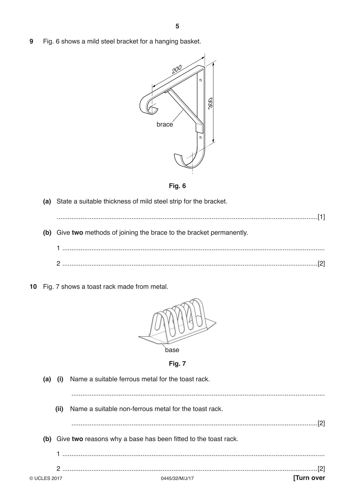
9 Fig. 6 shows a mild steel bracket for a hanging basket. 200 300 brace Fig. 6 (a) State a suitable thickness of mild steel strip for the bracket. ...............................................................................................................................................[1] (b) Give two methods of joining the brace to the bracket permanently. 1 ................................................................................................................................................ 2 ............................................................................................................................................[2]
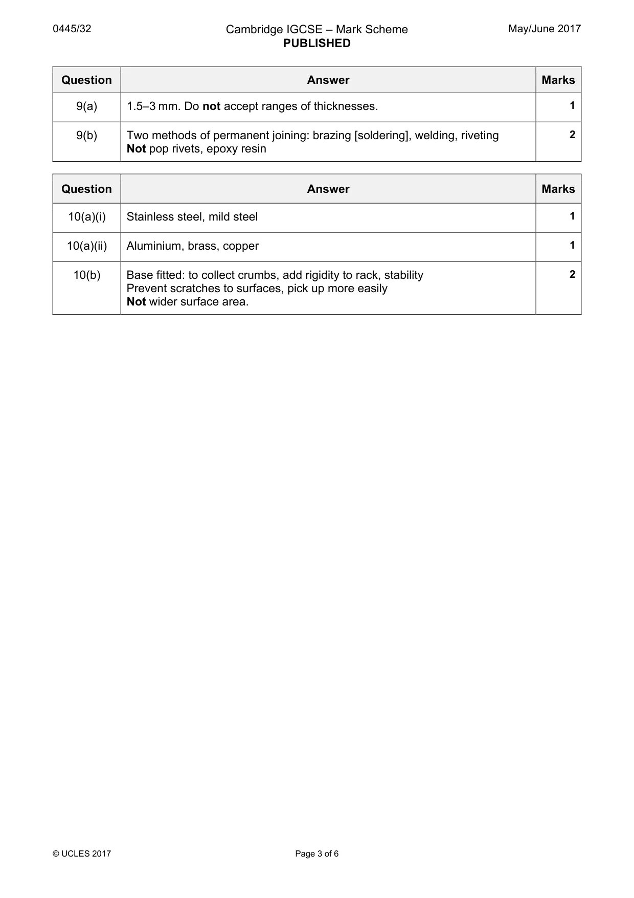
Mark scheme: 9(a) 1.5–3 mm. Do not accept ranges of thicknesses. 1 9(b) Two methods of permanent joining: brazing [soldering], welding, riveting 2 Not pop rivets, epoxy resin
Q10 · A toast rack made from metal
10 Fig. 7 shows a toast rack made from metal. base Fig. 7 (a) (i) Name a suitable ferrous metal for the toast rack. ........................................................................................................................................... (ii) Name a suitable non-ferrous metal for the toast rack. .......................................................................................................................................[2] (b) Give two reasons why a base has been fitted to the toast rack. 1 ................................................................................................................................................
Mark scheme: 10(a)(i) Stainless steel, mild steel 1 10(a)(ii) Aluminium, brass, copper 1 10(b) Base fitted: to collect crumbs, add rigidity to rack, stability 2 Prevent scratches to surfaces, pick up more easily Not wider surface area. Section B
Q11 · Views of an artist’s drawing board
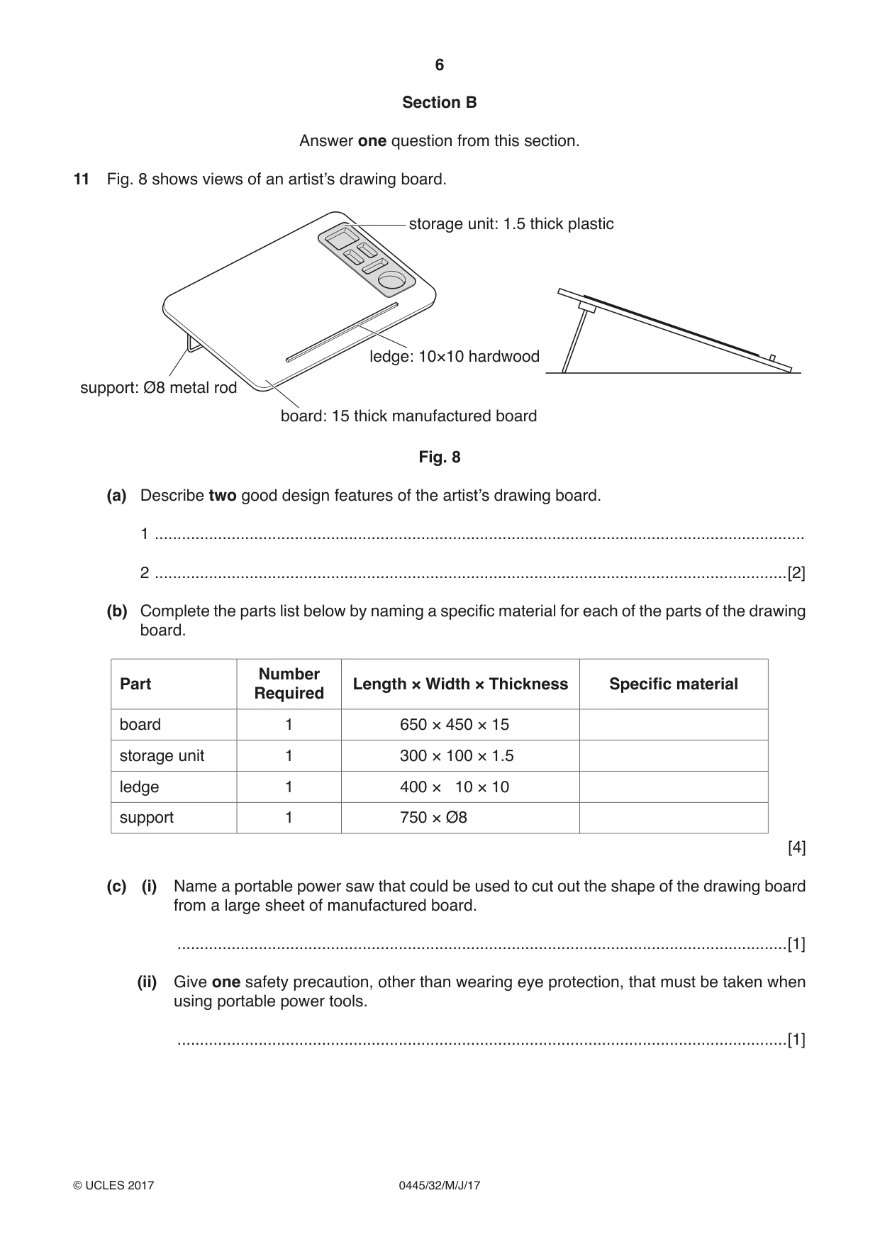
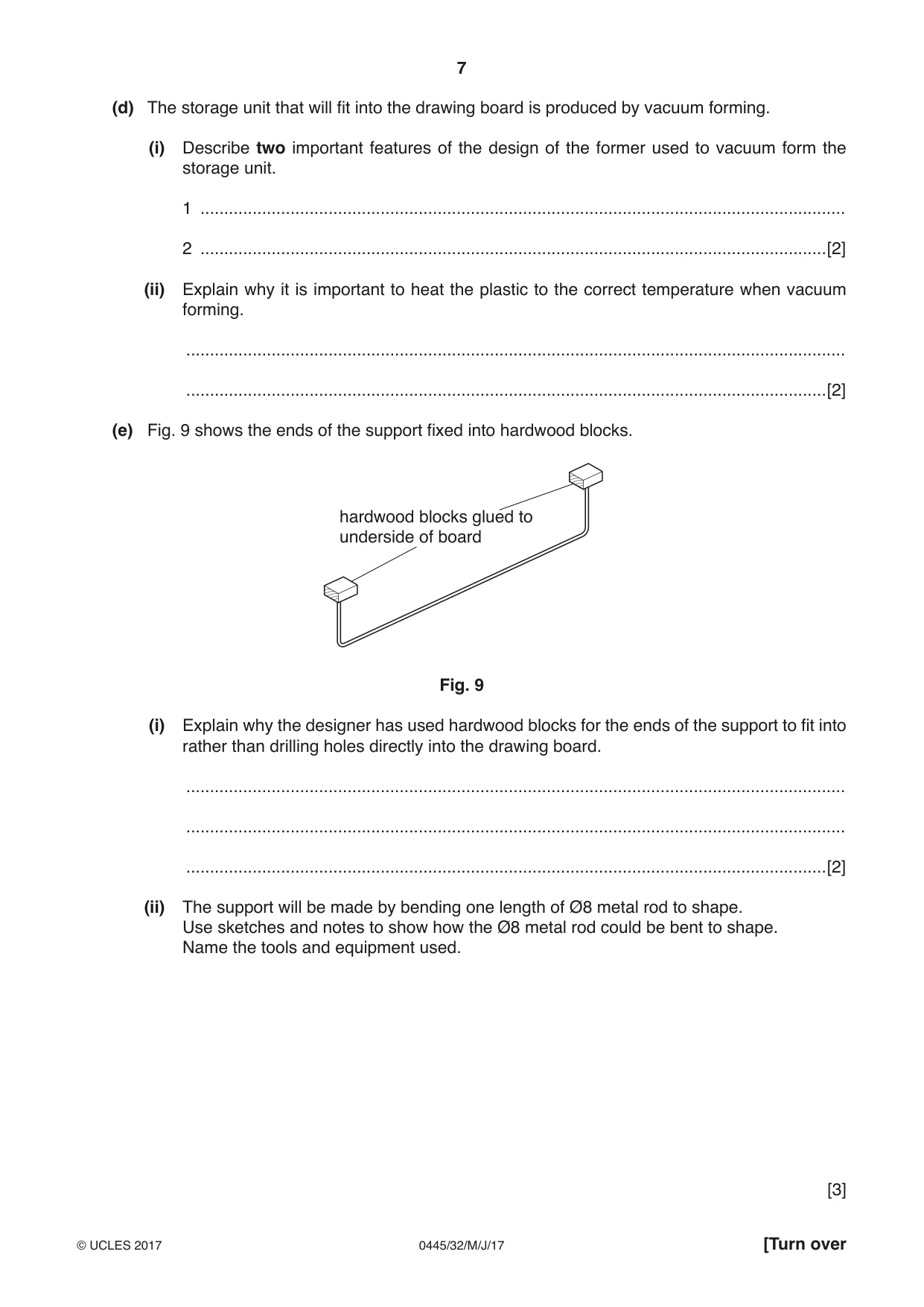
11 Fig. 8 shows views of an artist’s drawing board. storage unit: 1.5 thick plastic ledge: 10×10 hardwood support: Ø8 metal rod board: 15 thick manufactured board Fig. 8 (a) Describe two good design features of the artist’s drawing board. 1 ................................................................................................................................................ 2 ............................................................................................................................................[2] (b) Complete the parts list below by naming a specific material for each of the parts of the drawing board. Number Part Length × Width × Thickness Specific material Required board 1 650 × 450 × 15 storage unit 1 300 × 100 × 1.5 ledge 1 400 × 10 × 10 support 1 750 × Ø8 [4] (c) (i) Name a portable power saw that could be used to cut out the shape of the drawing board from a large sheet of manufactured board. .......................................................................................................................................[1] (ii) Give one safety precaution, other than wearing eye protection, that must be taken when using portable power tools. .......................................................................................................................................[1] (d) The storage unit that will fit into the drawing board is produced by vacuum forming. (i) Describe two important features of the design of the former used to vacuum form the storage unit. 1 ........................................................................................................................................ 2 ....................................................................................................................................[2] (ii) Explain why it is important to heat the plastic to the correct temperature when vacuum forming. ........................................................................................................................................... .......................................................................................................................................[2] (e) Fig. 9 shows the ends of the support fixed into hardwood blocks. hardwood blocks glued to underside of board Fig. 9 (i) Explain why the designer has used hardwood blocks for the ends of the support to fit into rather than drilling holes directly into the drawing board. ........................................................................................................................................... ........................................................................................................................................... .......................................................................................................................................[2] (ii) The support will be made by bending one length of Ø8 metal rod to shape. Use sketches and notes to show how the Ø8 metal rod could be bent to shape. Name the tools and equipment used. [3] (f) Use sketches and notes to show a different method of supporting the drawing board to that shown in Fig. 8. Include details of all materials and constructions used. [6] (g) Give two benefits of using a portable power sander to prepare the surface of the drawing board before a finish is applied. 1 ................................................................................................................................................ 2 ............................................................................................................................................[2]
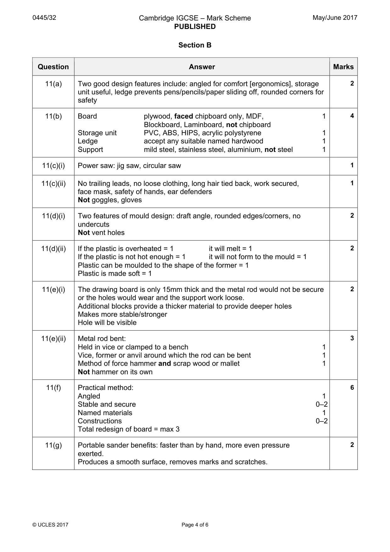
Mark scheme: 11(a) Two good design features include: angled for comfort [ergonomics], storage 2 unit useful, ledge prevents pens/pencils/paper sliding off, rounded corners for safety 11(b) Board plywood, faced chipboard only, MDF, 1 4 Blockboard, Laminboard, not chipboard Storage unit PVC, ABS, HIPS, acrylic polystyrene 1 Ledge accept any suitable named hardwood 1 Support mild steel, stainless steel, aluminium, not steel 1 11(c)(i) Power saw: jig saw, circular saw 1 11(c)(ii) No trailing leads, no loose clothing, long hair tied back, work secured, 1 face mask, safety of hands, ear defenders Not goggles, gloves 11(d)(i) Two features of mould design: draft angle, rounded edges/corners, no 2 undercuts Not vent holes 11(d)(ii) If the plastic is overheated = 1 it will melt = 1 2 If the plastic is not hot enough = 1 it will not form to the mould = 1 Plastic can be moulded to the shape of the former = 1 Plastic is made soft = 1 11(e)(i) The drawing board is only 15mm thick and the metal rod would not be secure 2 or the holes would wear and the support work loose. Additional blocks provide a thicker material to provide deeper holes Makes more stable/stronger Hole will be visible 11(e)(ii) Metal rod bent: 3 Held in vice or clamped to a bench 1 Vice, former or anvil around which the rod can be bent 1 Method of force hammer and scrap wood or mallet 1 Not hammer on its own 11(f) Practical method: 6 Angled 1 Stable and secure 0–2 Named materials 1 Constructions 0–2 Total redesign of board = max 3 11(g) Portable sander benefits: faster than by hand, more even pressure 2 exerted. Produces a smooth surface, removes marks and scratches.
Q12 · A bird feeder made from wood and plastic
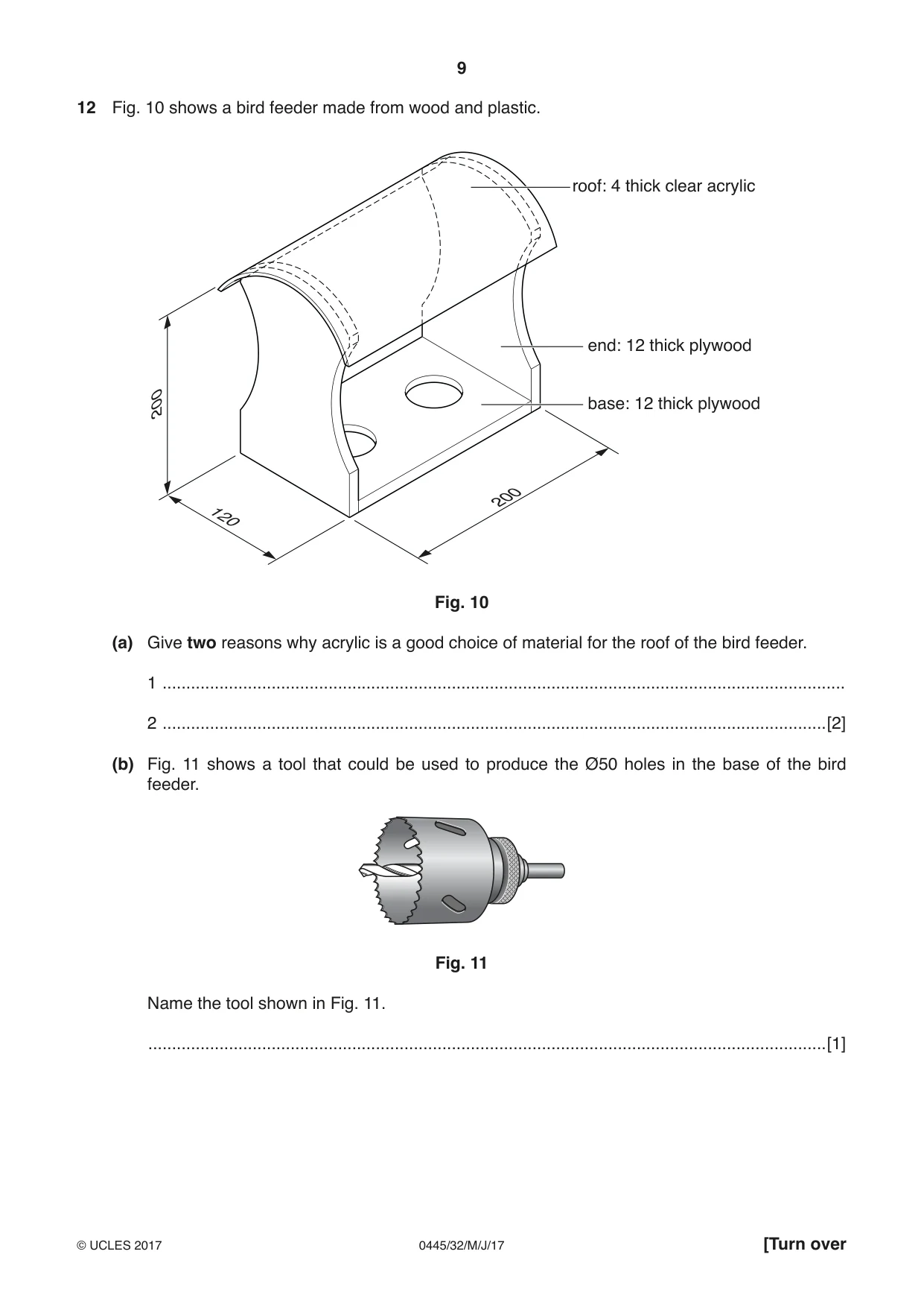
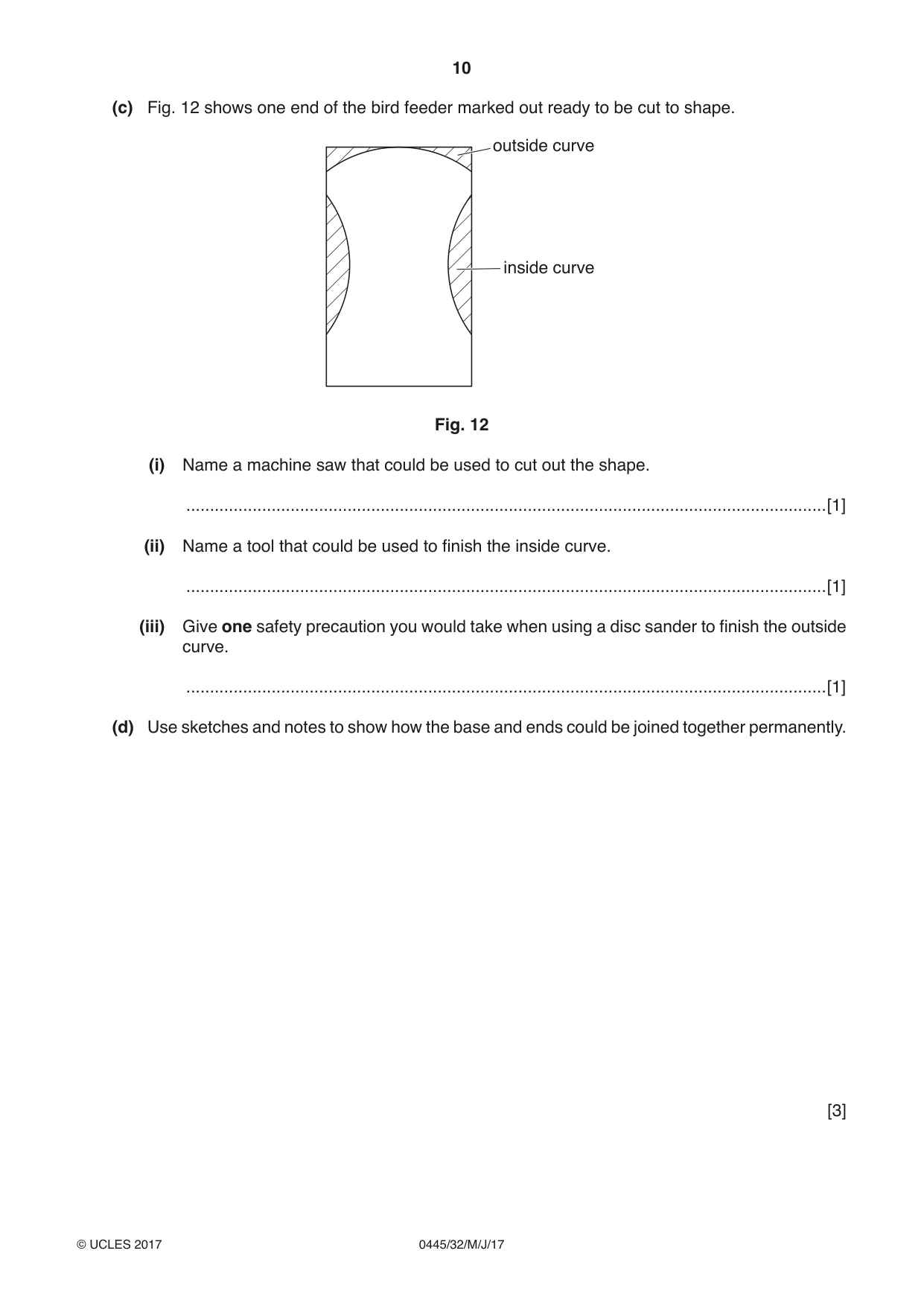
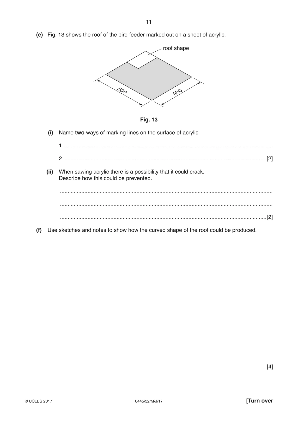
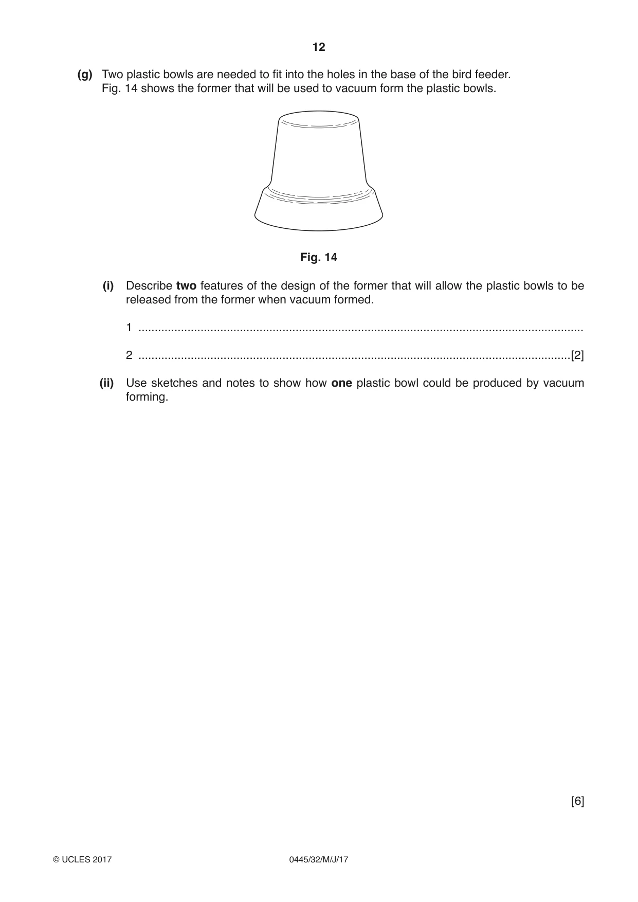
12 Fig. 10 shows a bird feeder made from wood and plastic. roof: 4 thick clear acrylic end: 12 thick plywood base: 12 thick plywood 200 200 120 Fig. 10 (a) Give two reasons why acrylic is a good choice of material for the roof of the bird feeder. 1 ................................................................................................................................................ 2 ............................................................................................................................................[2] (b) Fig. 11 shows a tool that could be used to produce the Ø50 holes in the base of the bird feeder. Fig. 11 Name the tool shown in Fig. 11. ...............................................................................................................................................[1] (c) Fig. 12 shows one end of the bird feeder marked out ready to be cut to shape. outside curve inside curve Fig. 12 (i) Name a machine saw that could be used to cut out the shape. .......................................................................................................................................[1] (ii) Name a tool that could be used to finish the inside curve. .......................................................................................................................................[1] (iii) Give one safety precaution you would take when using a disc sander to finish the outside curve. .......................................................................................................................................[1] (d) Use sketches and notes to show how the base and ends could be joined together permanently. [3] (e) Fig. 13 shows the roof of the bird feeder marked out on a sheet of acrylic. roof shape 500 400 Fig. 13 (i) Name two ways of marking lines on the surface of acrylic. 1 ........................................................................................................................................ 2 ....................................................................................................................................[2] (ii) When sawing acrylic there is a possibility that it could crack. Describe how this could be prevented. ........................................................................................................................................... ........................................................................................................................................... .......................................................................................................................................[2] (f) Use sketches and notes to show how the curved shape of the roof could be produced. [4] (g) Two plastic bowls are needed to fit into the holes in the base of the bird feeder. Fig. 14 shows the former that will be used to vacuum form the plastic bowls. Fig. 14 (i) Describe two features of the design of the former that will allow the plastic bowls to be released from the former when vacuum formed. 1 ........................................................................................................................................ 2 ....................................................................................................................................[2] (ii) Use sketches and notes to show how one plastic bowl could be produced by vacuum forming. [6]
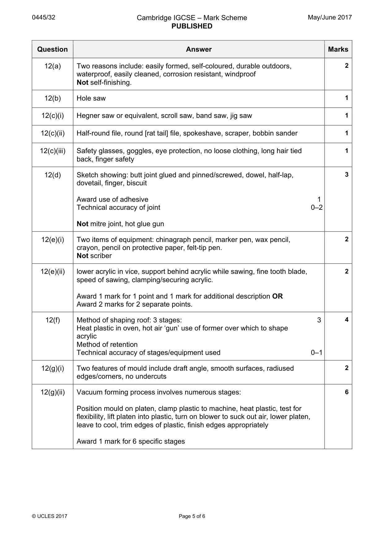
Mark scheme: 12(a) Two reasons include: easily formed, self-coloured, durable outdoors, 2 waterproof, easily cleaned, corrosion resistant, windproof Not self-finishing. 12(b) Hole saw 1 12(c)(i) Hegner saw or equivalent, scroll saw, band saw, jig saw 1 12(c)(ii) Half-round file, round [rat tail] file, spokeshave, scraper, bobbin sander 1 12(c)(iii) Safety glasses, goggles, eye protection, no loose clothing, long hair tied 1 back, finger safety 12(d) Sketch showing: butt joint glued and pinned/screwed, dowel, half-lap, 3 dovetail, finger, biscuit Award use of adhesive 1 Technical accuracy of joint 0–2 Not mitre joint, hot glue gun 12(e)(i) Two items of equipment: chinagraph pencil, marker pen, wax pencil, 2 crayon, pencil on protective paper, felt-tip pen. Not scriber 12(e)(ii) lower acrylic in vice, support behind acrylic while sawing, fine tooth blade, 2 speed of sawing, clamping/securing acrylic. Award 1 mark for 1 point and 1 mark for additional description OR Award 2 marks for 2 separate points. 12(f) Method of shaping roof: 3 stages: 3 4 Heat plastic in oven, hot air ‘gun’ use of former over which to shape acrylic Method of retention Technical accuracy of stages/equipment used 0–1 12(g)(i) Two features of mould include draft angle, smooth surfaces, radiused 2 edges/corners, no undercuts 12(g)(ii) Vacuum forming process involves numerous stages: 6 Position mould on platen, clamp plastic to machine, heat plastic, test for flexibility, lift platen into plastic, turn on blower to suck out air, lower platen, leave to cool, trim edges of plastic, finish edges appropriately Award 1 mark for 6 specific stages
Q13 · Views of a computer desk manufactured as flat-pack for self-assembly
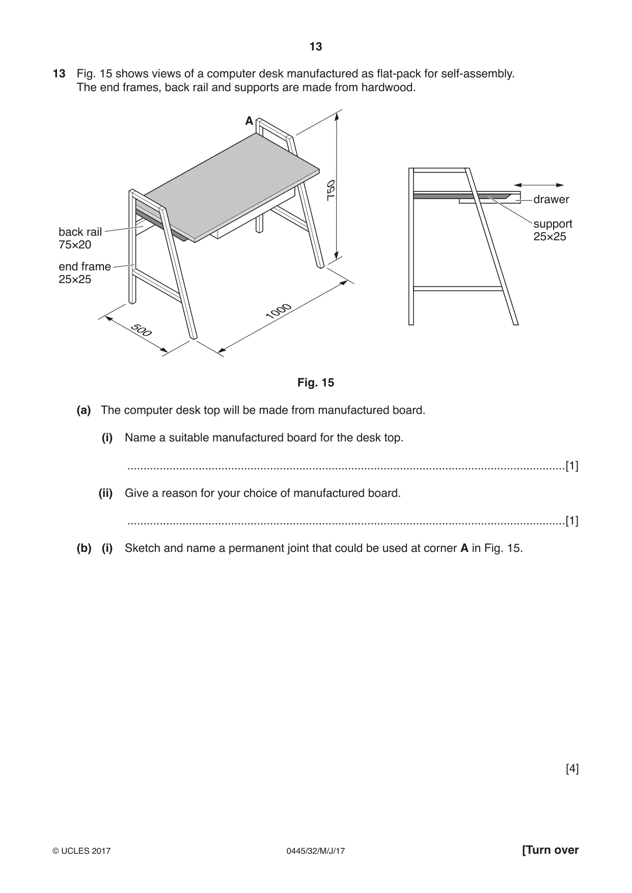
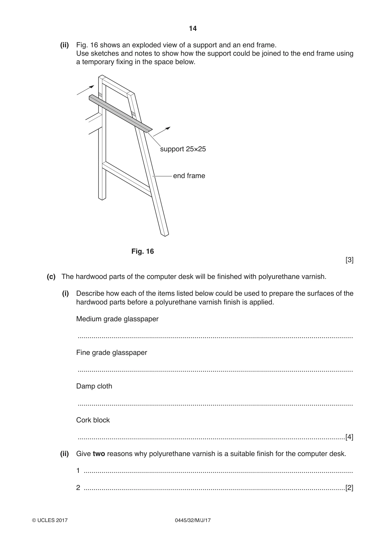
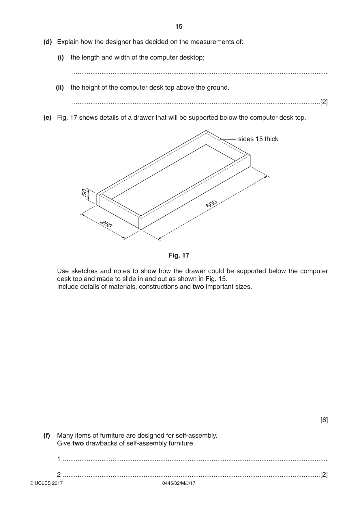
13 Fig. 15 shows views of a computer desk manufactured as flat-pack for self-assembly. The end frames, back rail and supports are made from hardwood. A 750 drawer support back rail 25×25 75×20 end frame 25×25 1000 500 Fig. 15 (a) The computer desk top will be made from manufactured board. (i) Name a suitable manufactured board for the desk top. .......................................................................................................................................[1] (ii) Give a reason for your choice of manufactured board. .......................................................................................................................................[1] (b) (i) Sketch and name a permanent joint that could be used at corner A in Fig. 15. [4] (ii) Fig. 16 shows an exploded view of a support and an end frame. Use sketches and notes to show how the support could be joined to the end frame using a temporary fixing in the space below. support 25×25 end frame Fig. 16 [3] (c) The hardwood parts of the computer desk will be finished with polyurethane varnish. (i) Describe how each of the items listed below could be used to prepare the surfaces of the hardwood parts before a polyurethane varnish finish is applied. Medium grade glasspaper ........................................................................................................................................... Fine grade glasspaper ........................................................................................................................................... Damp cloth ........................................................................................................................................... Cork block .......................................................................................................................................[4] (ii) Give two reasons why polyurethane varnish is a suitable finish for the computer desk. 1 ........................................................................................................................................ 2 ....................................................................................................................................[2] (d) Explain how the designer has decided on the measurements of: (i) the length and width of the computer desktop; ........................................................................................................................................... (ii) the height of the computer desk top above the ground. .......................................................................................................................................[2] (e) Fig. 17 shows details of a drawer that will be supported below the computer desk top. sides 15 thick 50 600 250 Fig. 17 Use sketches and notes to show how the drawer could be supported below the computer desk top and made to slide in and out as shown in Fig. 15. Include details of materials, constructions and two important sizes. [6] (f) Many items of furniture are designed for self-assembly. Give two drawbacks of self-assembly furniture. 1 ................................................................................................................................................
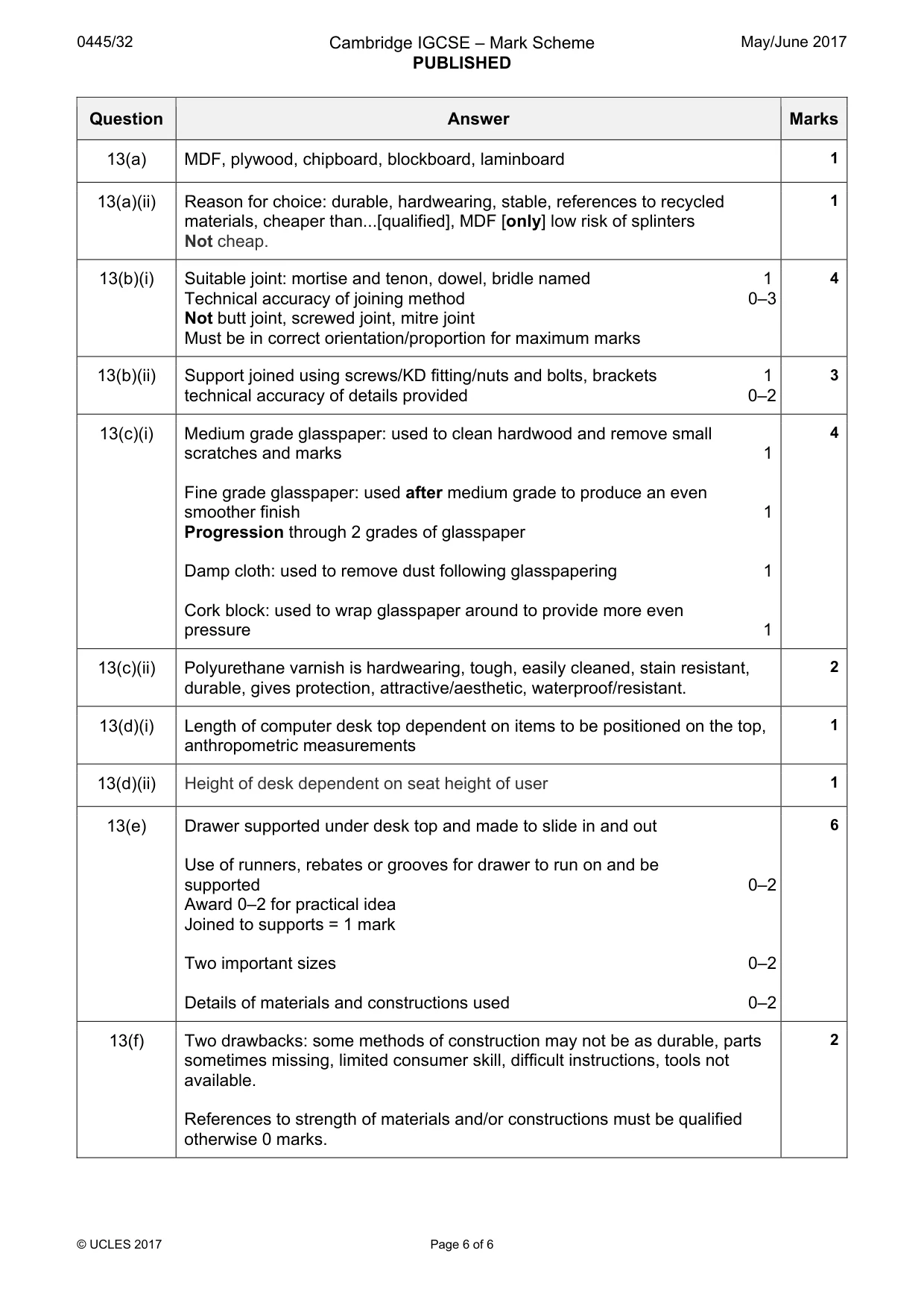
Mark scheme: 13(a) MDF, plywood, chipboard, blockboard, laminboard 1 13(a)(ii) Reason for choice: durable, hardwearing, stable, references to recycled 1 materials, cheaper than...[qualified], MDF [only] low risk of splinters Not cheap. 13(b)(i) Suitable joint: mortise and tenon, dowel, bridle named 1 4 Technical accuracy of joining method 0–3 Not butt joint, screwed joint, mitre joint Must be in correct orientation/proportion for maximum marks 13(b)(ii) Support joined using screws/KD fitting/nuts and bolts, brackets 1 3 technical accuracy of details provided 0–2 13(c)(i) Medium grade glasspaper: used to clean hardwood and remove small 4 scratches and marks 1 Fine grade glasspaper: used after medium grade to produce an even smoother finish 1 Progression through 2 grades of glasspaper Damp cloth: used to remove dust following glasspapering 1 Cork block: used to wrap glasspaper around to provide more even pressure 1 13(c)(ii) Polyurethane varnish is hardwearing, tough, easily cleaned, stain resistant, 2 durable, gives protection, attractive/aesthetic, waterproof/resistant. 13(d)(i) Length of computer desk top dependent on items to be positioned on the top, 1 anthropometric measurements 13(d)(ii) Height of desk dependent on seat height of user 1 13(e) Drawer supported under desk top and made to slide in and out 6 Use of runners, rebates or grooves for drawer to run on and be supported 0–2 Award 0–2 for practical idea Joined to supports = 1 mark Two important sizes 0–2 Details of materials and constructions used 0–2 13(f) Two drawbacks: some methods of construction may not be as durable, parts 2 sometimes missing, limited consumer skill, difficult instructions, tools not available. References to strength of materials and/or constructions must be qualified otherwise 0 marks.
What was in this paper
The subtopics covered by these 13 questions, and how many questions each got. Open one in a new tab to see every Cambridge question on it.
What you needed in this session
Cambridge’s own grade thresholds for 2017 May/June, Paper 3 · Variant 2. A higher threshold means an easier paper — the bar moves with how the cohort did.