Cambridge IGCSE Design and Technology 0445 — 2017 May/June Paper 3 · Variant 1
0445/31/M/J/17 · 13 questions · 50 marks · ≈56 min
The question paper and its mark scheme, free to read here and free to download. This is Cambridge’s own paper, exactly as it was sat.
Question paper20 pages


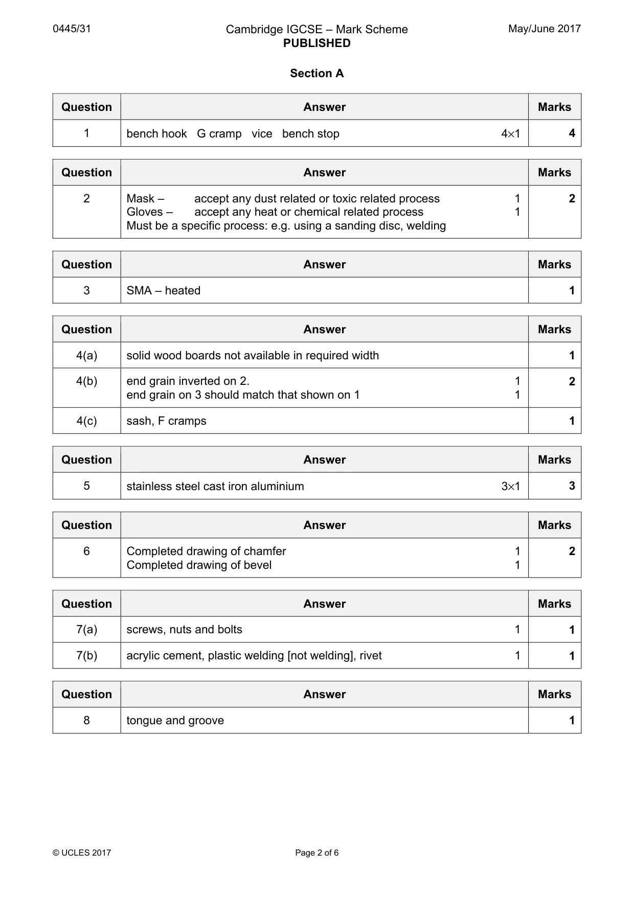
Mark scheme6 pages
Answers below. Sit the paper first if you are practising.
Questions as text
Q1 · Complete the table below by naming each of the tools or items of equipment used to hold…
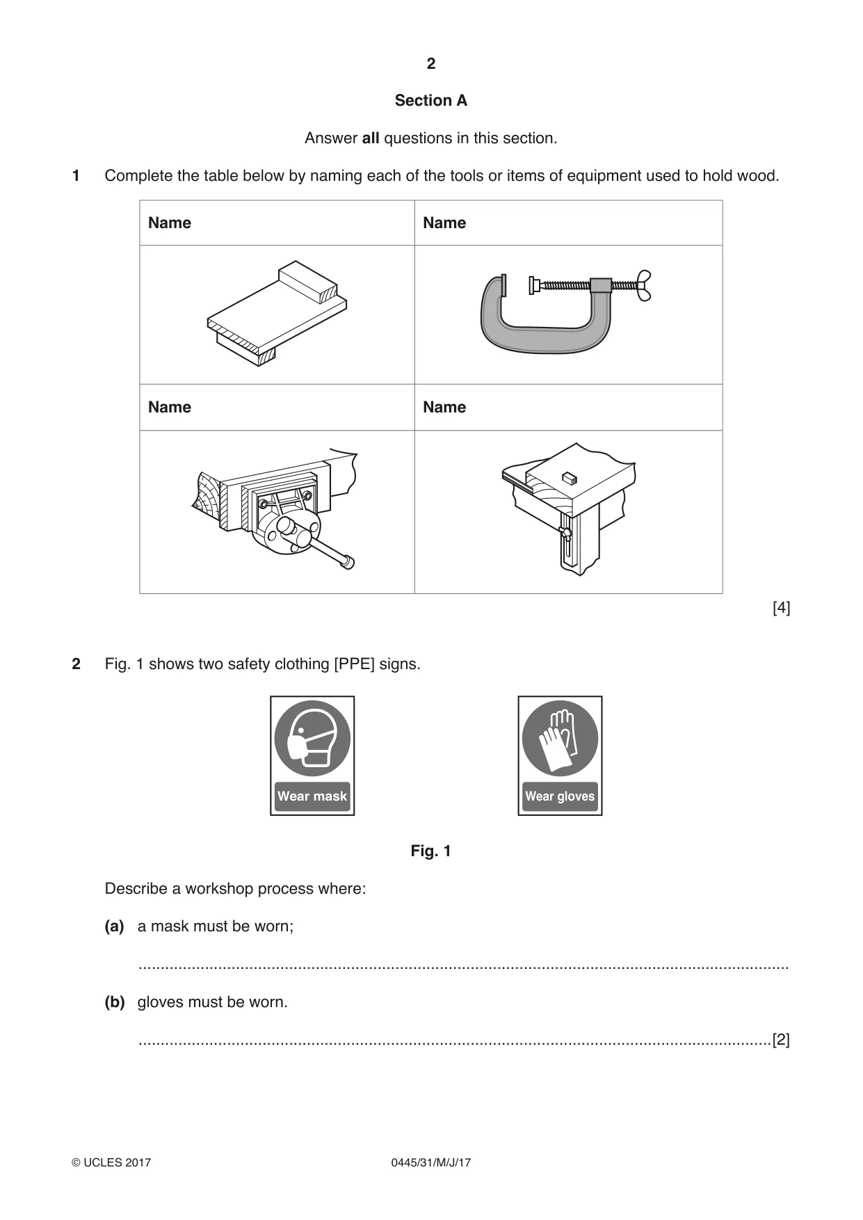
1 Complete the table below by naming each of the tools or items of equipment used to hold wood. Name Name Name Name [4]
Mark scheme: Question Answer Marks 1 bench hook G cramp vice bench stop 4×1 4
Q2 · Two safety clothing [PPE] signs
2 Fig. 1 shows two safety clothing [PPE] signs. Wear mask Wear gloves Fig. 1 Describe a workshop process where: (a) a mask must be worn; ................................................................................................................................................... (b) gloves must be worn. ...............................................................................................................................................[2]
Mark scheme: 2 Mask – accept any dust related or toxic related process 1 2 Gloves – accept any heat or chemical related process 1 Must be a specific process: e.g. using a sanding disc, welding
Q3 · Shape Memory Alloy [SMA] is an example of a ‘smart’ material
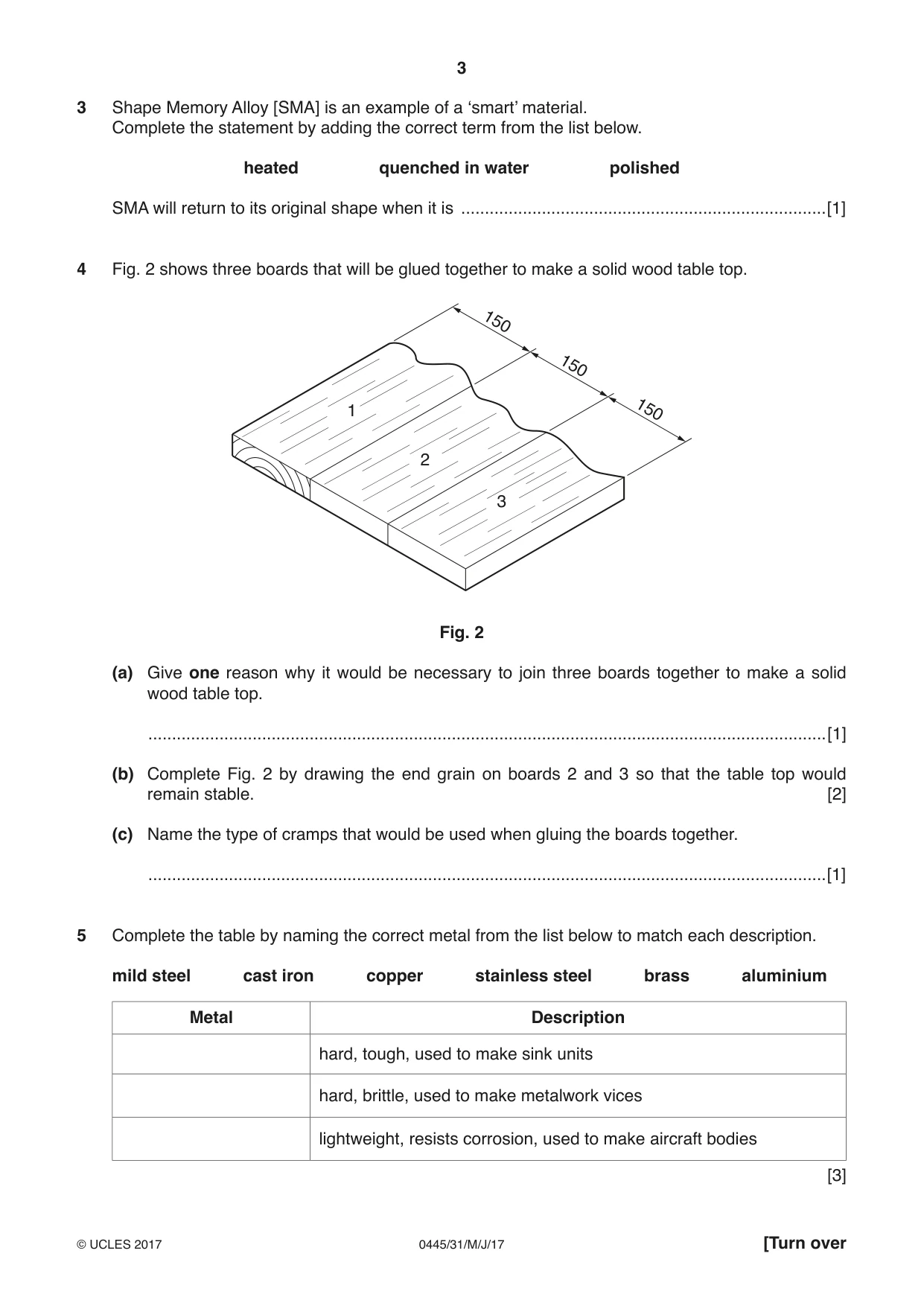
3 Shape Memory Alloy [SMA] is an example of a ‘smart’ material. Complete the statement by adding the correct term from the list below. heated quenched in water polished SMA will return to its original shape when it is .............................................................................[1]
Mark scheme: 3 SMA – heated 1
Q4 · Three boards that will be glued together to make a solid wood table top
4 Fig. 2 shows three boards that will be glued together to make a solid wood table top. 150 150 1 150 2 3 Fig. 2 (a) Give one reason why it would be necessary to join three boards together to make a solid wood table top. ...............................................................................................................................................[1] (b) Complete Fig. 2 by drawing the end grain on boards 2 and 3 so that the table top would remain stable. [2] (c) Name the type of cramps that would be used when gluing the boards together. ...............................................................................................................................................[1]
Mark scheme: 4(a) solid wood boards not available in required width 1 4(b) end grain inverted on 2. 1 2 end grain on 3 should match that shown on 1 1 4(c) sash, F cramps 1
Q5 · Complete the table by naming the correct metal from the list below to match each…
5 Complete the table by naming the correct metal from the list below to match each description. mild steel cast iron copper stainless steel brass aluminium Metal Description hard, tough, used to make sink units hard, brittle, used to make metalwork vices lightweight, resists corrosion, used to make aircraft bodies [3]
Mark scheme: 5 stainless steel cast iron aluminium 3×1 3
Q6 · The end of a length of wood
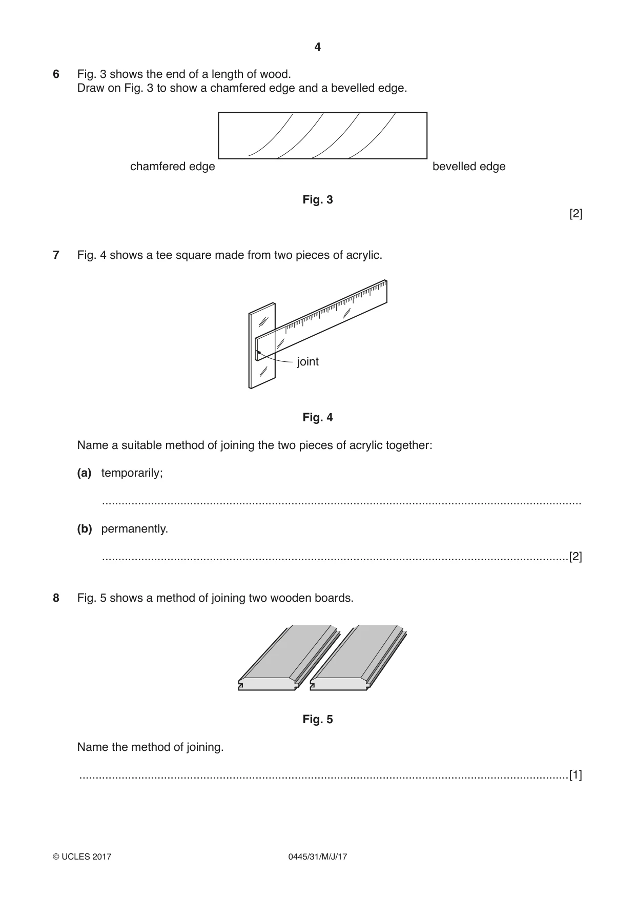
6 Fig. 3 shows the end of a length of wood. Draw on Fig. 3 to show a chamfered edge and a bevelled edge. chamfered edge bevelled edge Fig. 3 [2]
Mark scheme: 6 Completed drawing of chamfer 1 2 Completed drawing of bevel 1
Q7 · A tee square made from two pieces of acrylic
7 Fig. 4 shows a tee square made from two pieces of acrylic. joint Fig. 4 Name a suitable method of joining the two pieces of acrylic together: (a) temporarily; ................................................................................................................................................... (b) permanently. ...............................................................................................................................................[2]
Mark scheme: 7(a) screws, nuts and bolts 1 1 7(b) acrylic cement, plastic welding [not welding], rivet 1 1
Q8 · A method of joining two wooden boards
8 Fig. 5 shows a method of joining two wooden boards. Fig. 5 Name the method of joining. ......................................................................................................................................................[1]
Mark scheme: 8 tongue and groove 1
Question 9
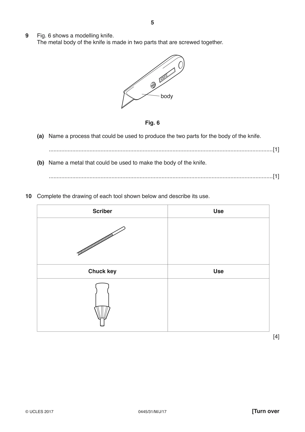
9 Fig. 6 shows a modelling knife. The metal body of the knife is made in two parts that are screwed together. body Fig. 6 (a) Name a process that could be used to produce the two parts for the body of the knife. ...............................................................................................................................................[1] (b) Name a metal that could be used to make the body of the knife. ...............................................................................................................................................[1]
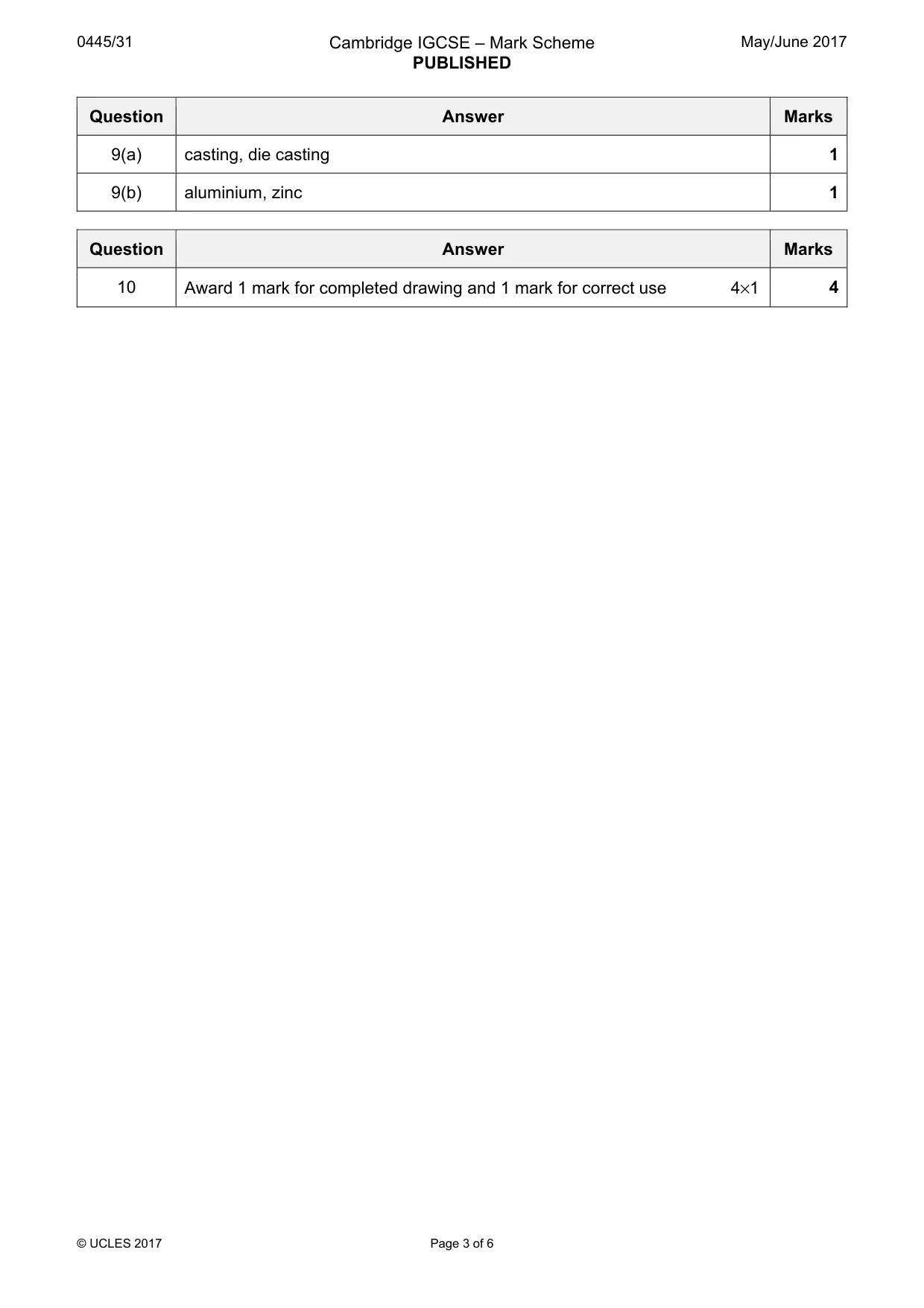
Mark scheme: 9(a) casting, die casting 1 9(b) aluminium, zinc 1
Q10 · Complete the drawing of each tool shown below and describe its use
10 Complete the drawing of each tool shown below and describe its use. Scriber Use Chuck key Use [4]
Mark scheme: 10 Award 1 mark for completed drawing and 1 mark for correct use 4×1 4 Section B
Q11 · Views of a child’s table and a parts list
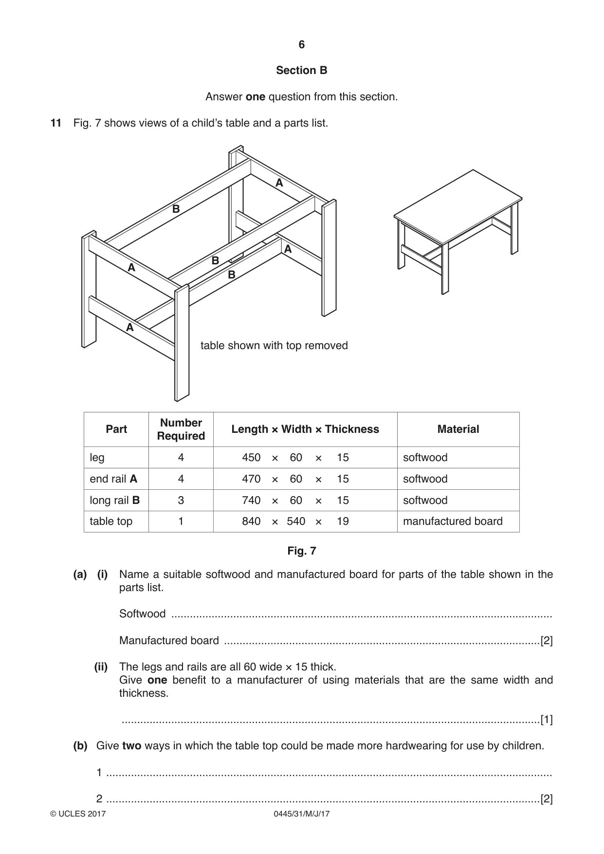
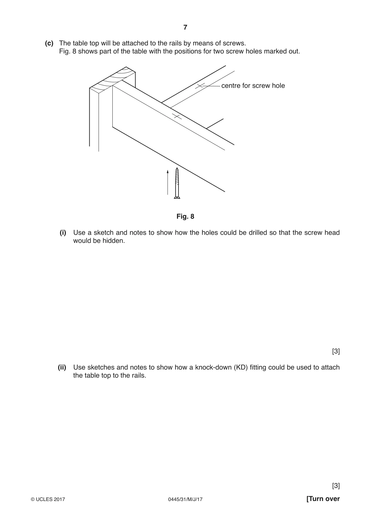
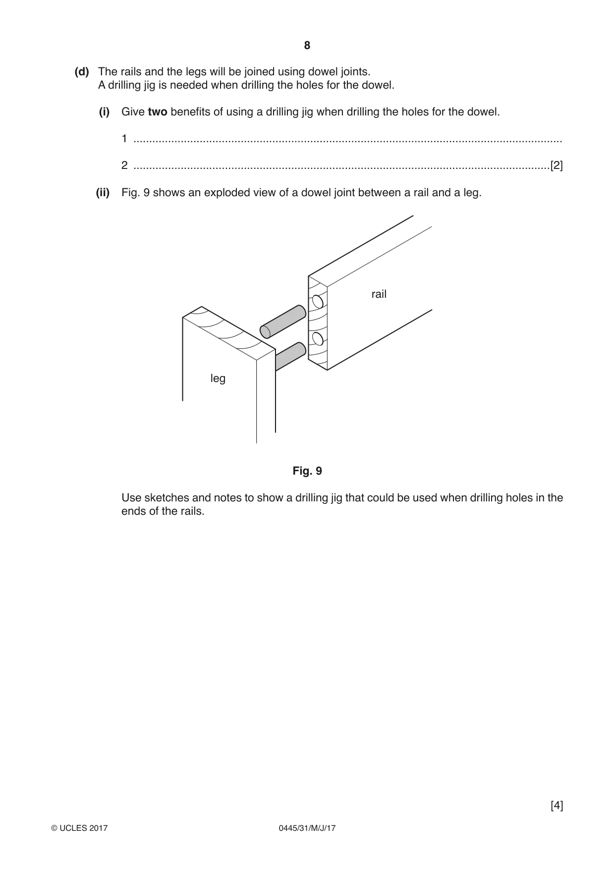
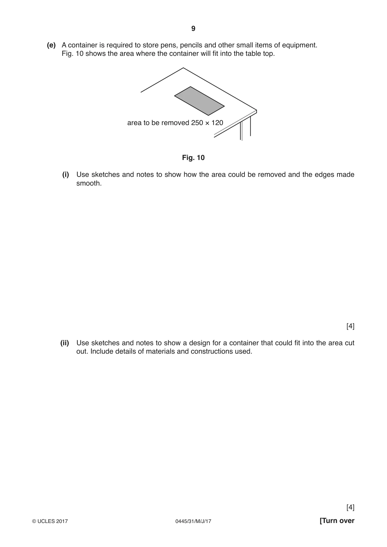
11 Fig. 7 shows views of a child’s table and a parts list. A B A B A B A table shown with top removed Number Part Length × Width × Thickness Material Required leg 4 450 × 60 × 15 softwood end rail A 4 470 × 60 × 15 softwood long rail B 3 740 × 60 × 15 softwood table top 1 840 × 540 × 19 manufactured board Fig. 7 (a) (i) Name a suitable softwood and manufactured board for parts of the table shown in the parts list. Softwood ........................................................................................................................... Manufactured board ......................................................................................................[2] (ii) The legs and rails are all 60 wide × 15 thick. Give one benefit to a manufacturer of using materials that are the same width and thickness. .......................................................................................................................................[1] (b) Give two ways in which the table top could be made more hardwearing for use by children. 1 ................................................................................................................................................ 2 ............................................................................................................................................[2] (c) The table top will be attached to the rails by means of screws. Fig. 8 shows part of the table with the positions for two screw holes marked out. centre for screw hole Fig. 8 (i) Use a sketch and notes to show how the holes could be drilled so that the screw head would be hidden. [3] (ii) Use sketches and notes to show how a knock-down (KD) fitting could be used to attach the table top to the rails. [3] (d) The rails and the legs will be joined using dowel joints. A drilling jig is needed when drilling the holes for the dowel. (i) Give two benefits of using a drilling jig when drilling the holes for the dowel. 1 ........................................................................................................................................ 2 ....................................................................................................................................[2] (ii) Fig. 9 shows an exploded view of a dowel joint between a rail and a leg. rail leg Fig. 9 Use sketches and notes to show a drilling jig that could be used when drilling holes in the ends of the rails. [4] (e) A container is required to store pens, pencils and other small items of equipment. Fig. 10 shows the area where the container will fit into the table top. area to be removed 250 × 120 Fig. 10 (i) Use sketches and notes to show how the area could be removed and the edges made smooth. [4] (ii) Use sketches and notes to show a design for a container that could fit into the area cut out. Include details of materials and constructions used. [4]
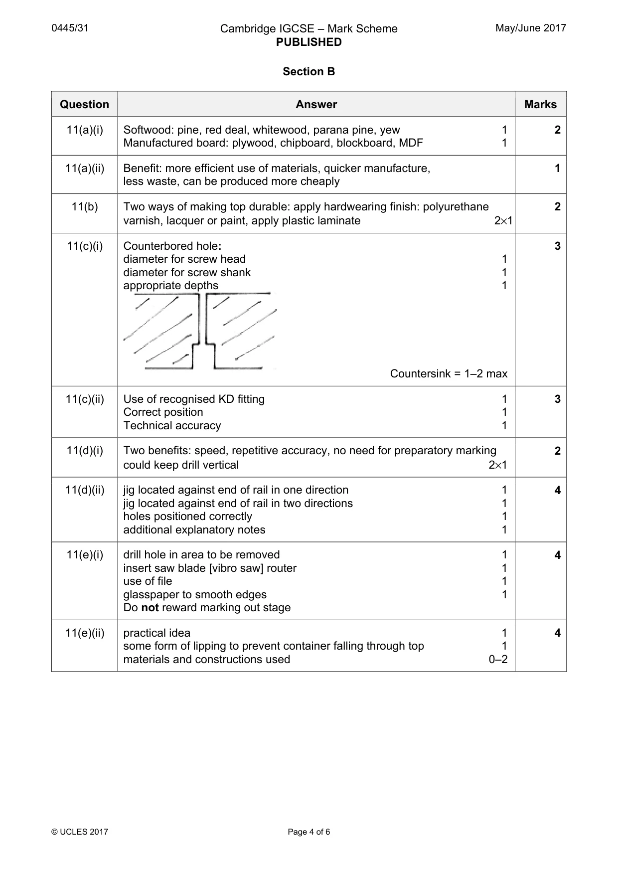
Mark scheme: 11(a)(i) Softwood: pine, red deal, whitewood, parana pine, yew 1 2 Manufactured board: plywood, chipboard, blockboard, MDF 1 11(a)(ii) Benefit: more efficient use of materials, quicker manufacture, 1 less waste, can be produced more cheaply 11(b) Two ways of making top durable: apply hardwearing finish: polyurethane 2 varnish, lacquer or paint, apply plastic laminate 2×1 11(c)(i) Counterbored hole: 3 diameter for screw head 1 diameter for screw shank 1 appropriate depths 1 Countersink = 1–2 max 11(c)(ii) Use of recognised KD fitting 1 3 Correct position 1 Technical accuracy 1 11(d)(i) Two benefits: speed, repetitive accuracy, no need for preparatory marking 2 could keep drill vertical 2×1 11(d)(ii) jig located against end of rail in one direction 1 4 jig located against end of rail in two directions 1 holes positioned correctly 1 additional explanatory notes 1 11(e)(i) drill hole in area to be removed 1 4 insert saw blade [vibro saw] router 1 use of file 1 glasspaper to smooth edges 1 Do not reward marking out stage 11(e)(ii) practical idea 1 4 some form of lipping to prevent container falling through top 1 materials and constructions used 0–2
Q12 · Views of a cycle rack that could be fixed to the wall of a garage or shed
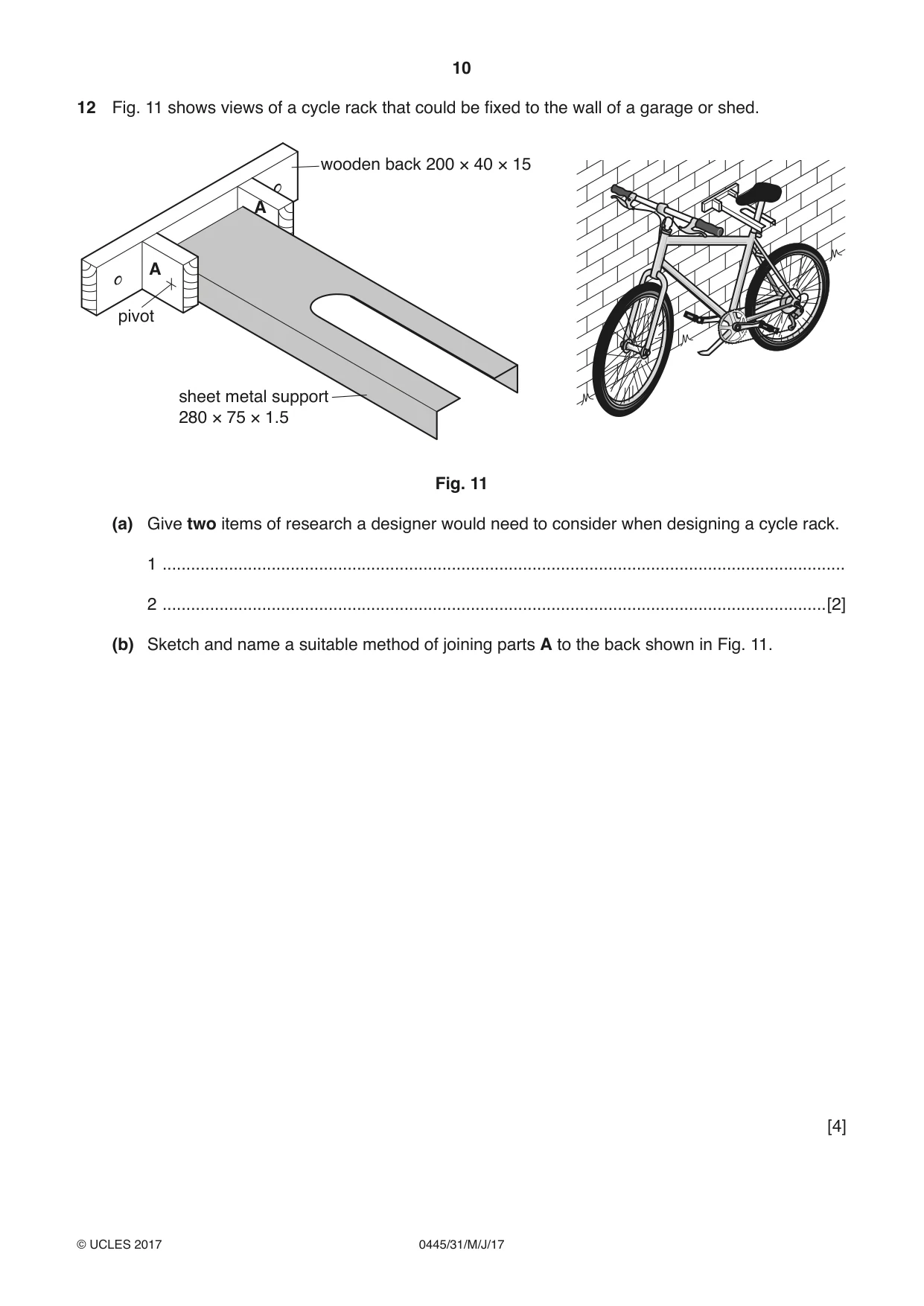
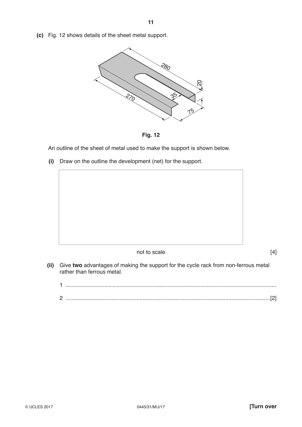
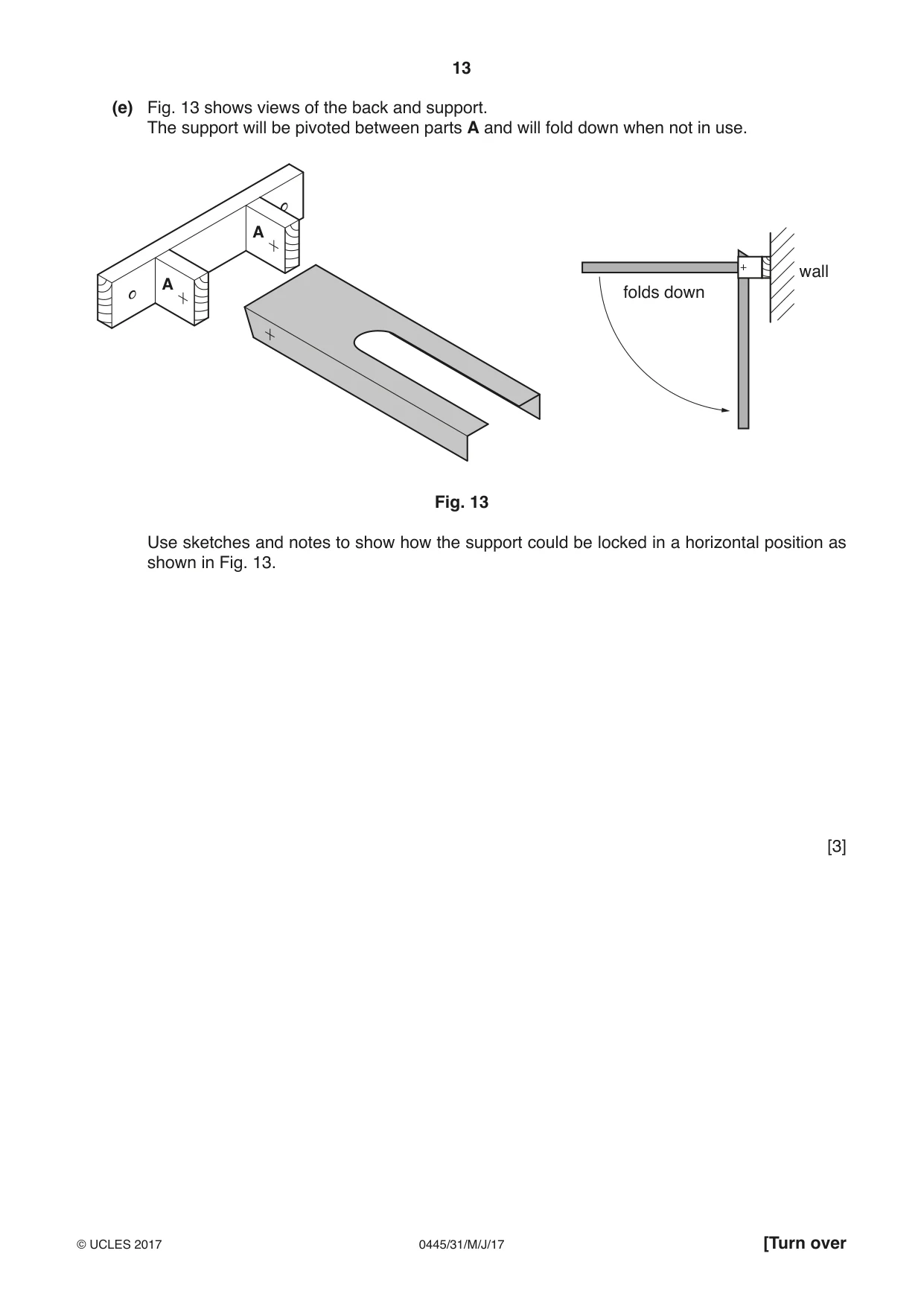
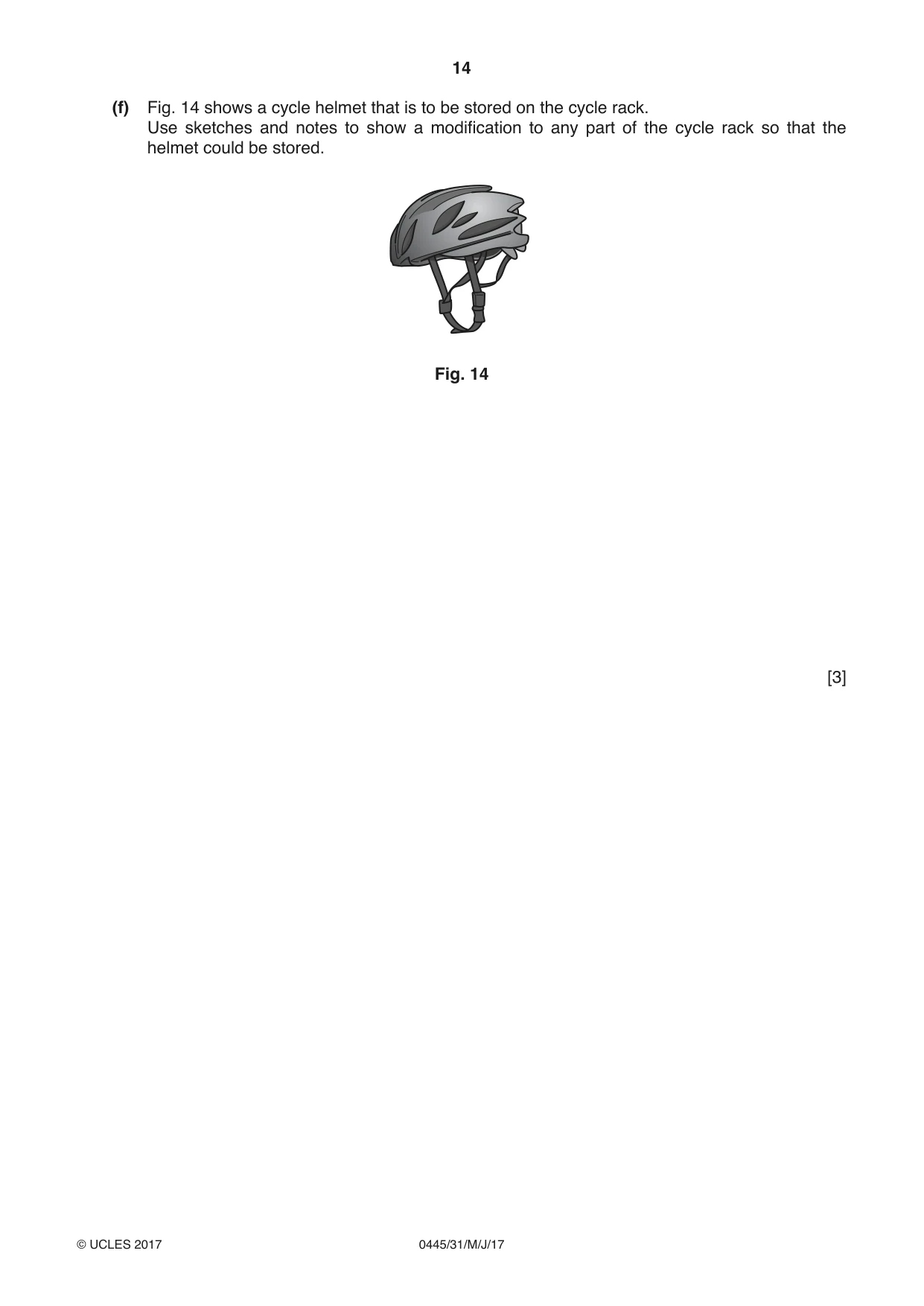
12 Fig. 11 shows views of a cycle rack that could be fixed to the wall of a garage or shed. wooden back 200 × 40 × 15 A A pivot sheet metal support 280 × 75 × 1.5 Fig. 11 (a) Give two items of research a designer would need to consider when designing a cycle rack. 1 ................................................................................................................................................ 2 ............................................................................................................................................[2] (b) Sketch and name a suitable method of joining parts A to the back shown in Fig. 11. [4] (c) Fig. 12 shows details of the sheet metal support. 280 20 270 35 75 Fig. 12 An outline of the sheet of metal used to make the support is shown below. (i) Draw on the outline the development (net) for the support. not to scale [4] (ii) Give two advantages of making the support for the cycle rack from non-ferrous metal rather than ferrous metal. 1 ........................................................................................................................................ 2 ....................................................................................................................................[2] (d) To make the support, the slot will be cut out and the metal will be bent to shape. (i) Use sketches and notes to show how the slot could be cut out and the edges made smooth. [4] (ii) Use sketches and notes to show how the sheet metal could be bent to shape. [3] (e) Fig. 13 shows views of the back and support. The support will be pivoted between parts A and will fold down when not in use. A wall A folds down Fig. 13 Use sketches and notes to show how the support could be locked in a horizontal position as shown in Fig. 13. [3] (f) Fig. 14 shows a cycle helmet that is to be stored on the cycle rack. Use sketches and notes to show a modification to any part of the cycle rack so that the helmet could be stored. Fig. 14 [3]
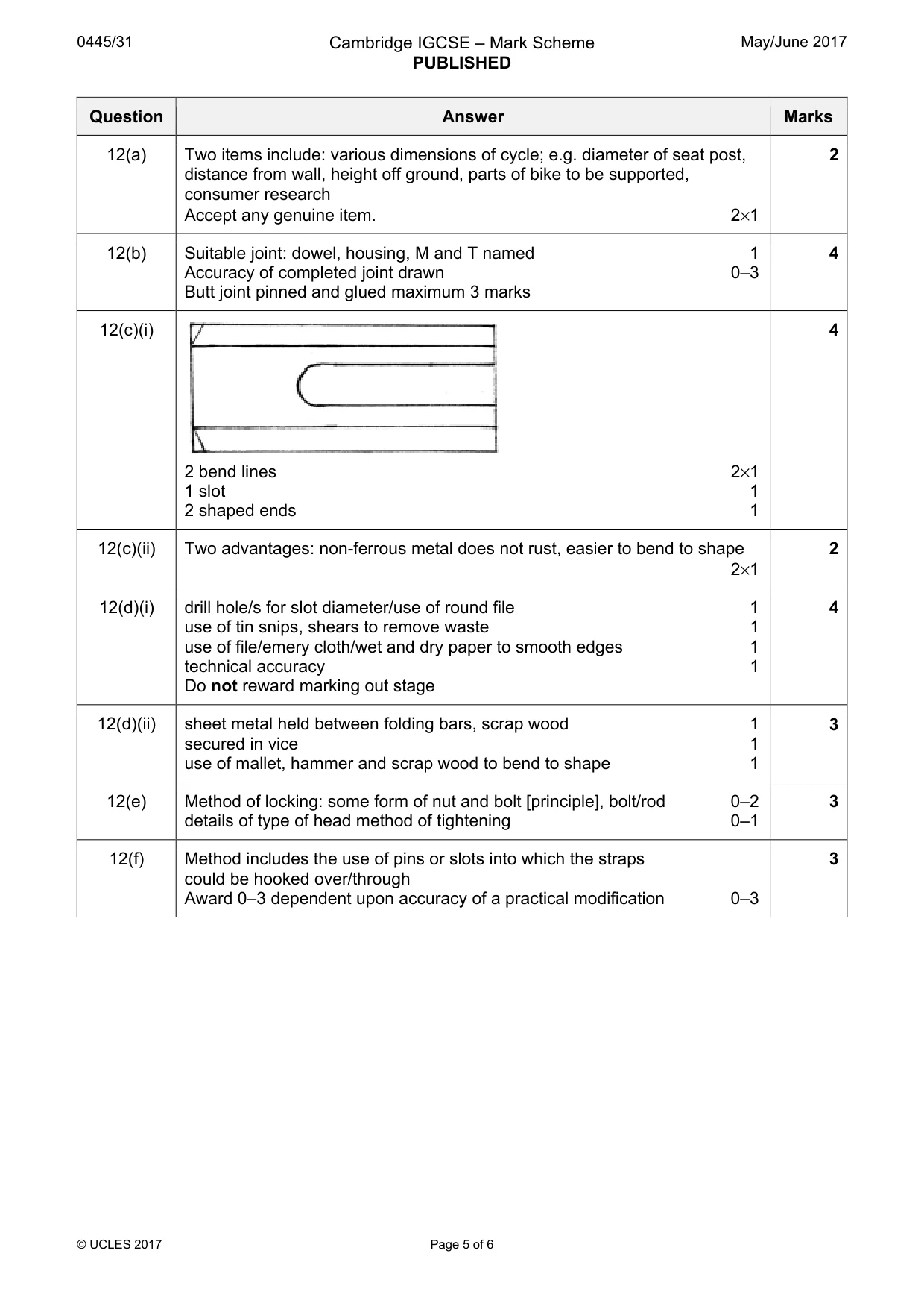
Mark scheme: 12(a) Two items include: various dimensions of cycle; e.g. diameter of seat post, 2 distance from wall, height off ground, parts of bike to be supported, consumer research Accept any genuine item. 2×1 12(b) Suitable joint: dowel, housing, M and T named 1 4 Accuracy of completed joint drawn 0–3 Butt joint pinned and glued maximum 3 marks 12(c)(i) 4 2 bend lines 2×1 1 slot 1 2 shaped ends 1 12(c)(ii) Two advantages: non-ferrous metal does not rust, easier to bend to shape 2 2×1 12(d)(i) drill hole/s for slot diameter/use of round file 1 4 use of tin snips, shears to remove waste 1 use of file/emery cloth/wet and dry paper to smooth edges 1 technical accuracy 1 Do not reward marking out stage 12(d)(ii) sheet metal held between folding bars, scrap wood 1 3 secured in vice 1 use of mallet, hammer and scrap wood to bend to shape 1 12(e) Method of locking: some form of nut and bolt [principle], bolt/rod 0–2 3 details of type of head method of tightening 0–1 12(f) Method includes the use of pins or slots into which the straps 3 could be hooked over/through Award 0–3 dependent upon accuracy of a practical modification 0–3
Q13 · An incomplete design for a toy lorry
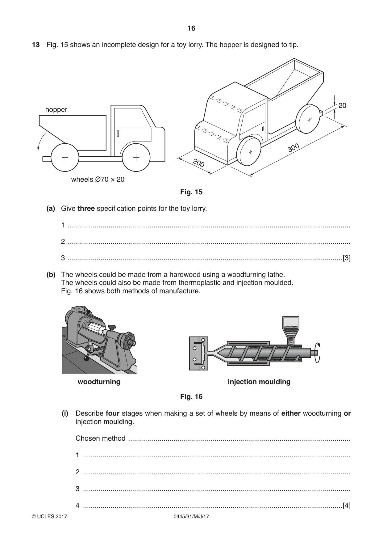
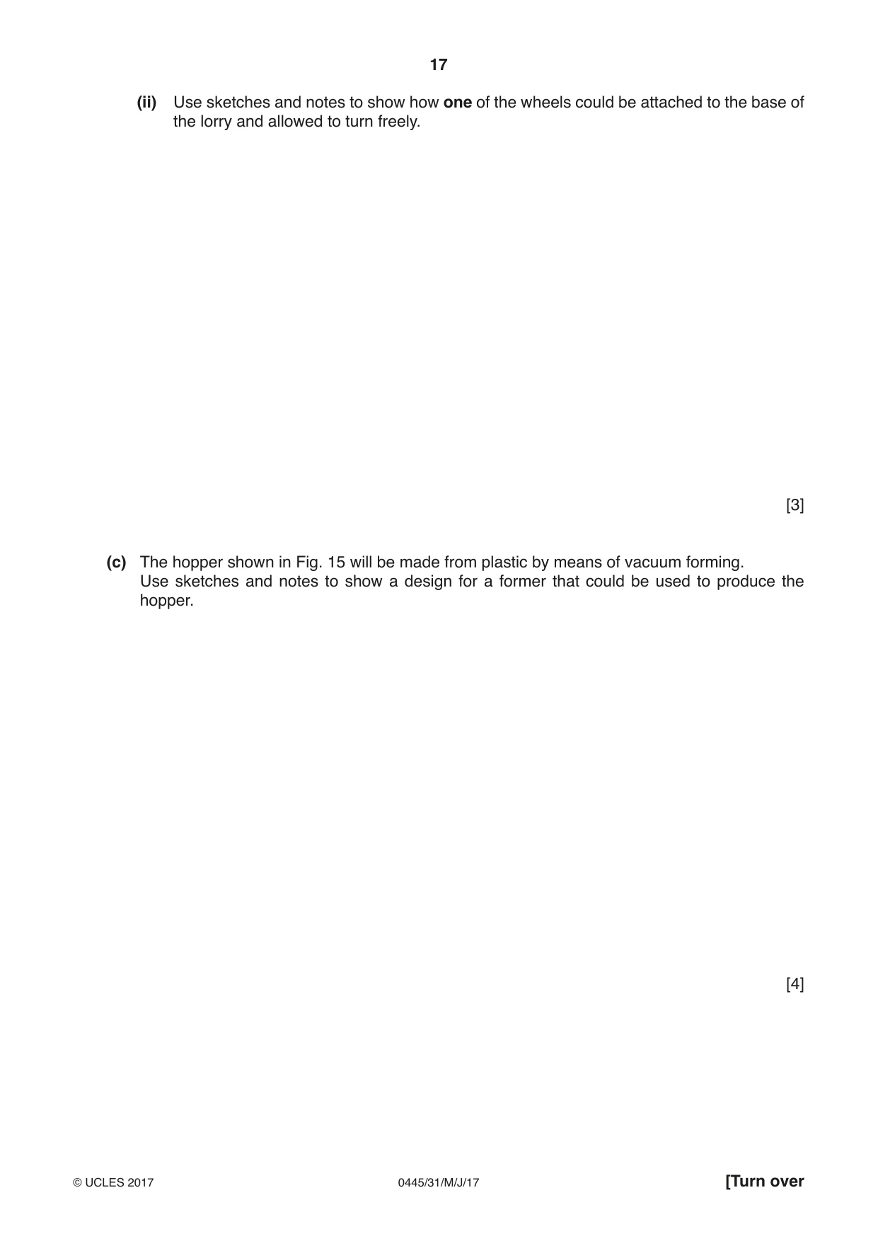
13 Fig. 15 shows an incomplete design for a toy lorry. The hopper is designed to tip. 20 hopper 300 200 wheels Ø70 × 20 Fig. 15 (a) Give three specification points for the toy lorry. 1 ................................................................................................................................................ 2 ................................................................................................................................................ 3 ............................................................................................................................................[3] (b) The wheels could be made from a hardwood using a woodturning lathe. The wheels could also be made from thermoplastic and injection moulded. Fig. 16 shows both methods of manufacture. woodturning injection moulding Fig. 16 (i) Describe four stages when making a set of wheels by means of either woodturning or injection moulding. Chosen method ................................................................................................................. 1 ........................................................................................................................................ 2 ........................................................................................................................................ 3 ........................................................................................................................................ 4 ....................................................................................................................................[4] (ii) Use sketches and notes to show how one of the wheels could be attached to the base of the lorry and allowed to turn freely. [3] (c) The hopper shown in Fig. 15 will be made from plastic by means of vacuum forming. Use sketches and notes to show a design for a former that could be used to produce the hopper. [4] (d) Use sketches and notes to show how the hopper could be made to tip as shown in Fig. 15. Include details of materials, fittings and constructions used. [6] (e) Wooden toys can be painted or varnished to protect the wood. Give one additional benefit of using: (i) paint; ................................................................................................................................. ........................................................................................................................................... (ii) varnish. .............................................................................................................................. .......................................................................................................................................[2] (f) Explain the benefits to a manufacturer of producing children’s toys made from plastic rather than wood-based materials. ................................................................................................................................................... ................................................................................................................................................... ................................................................................................................................................... ...............................................................................................................................................[3]
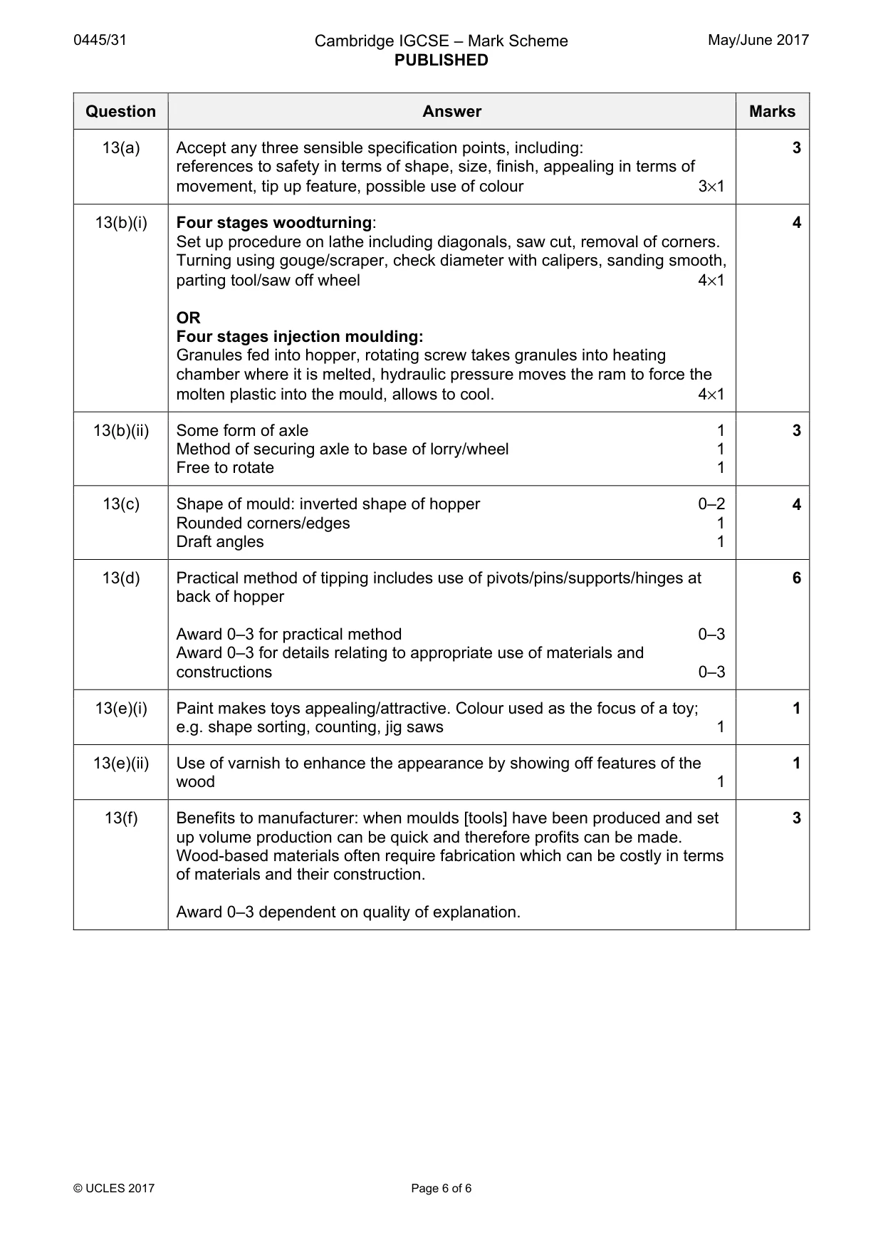
Mark scheme: 13(a) Accept any three sensible specification points, including: 3 references to safety in terms of shape, size, finish, appealing in terms of movement, tip up feature, possible use of colour 3×1 13(b)(i) Four stages woodturning: 4 Set up procedure on lathe including diagonals, saw cut, removal of corners. Turning using gouge/scraper, check diameter with calipers, sanding smooth, parting tool/saw off wheel 4×1 OR Four stages injection moulding: Granules fed into hopper, rotating screw takes granules into heating chamber where it is melted, hydraulic pressure moves the ram to force the molten plastic into the mould, allows to cool. 4×1 13(b)(ii) Some form of axle 1 3 Method of securing axle to base of lorry/wheel 1 Free to rotate 1 13(c) Shape of mould: inverted shape of hopper 0–2 4 Rounded corners/edges 1 Draft angles 1 13(d) Practical method of tipping includes use of pivots/pins/supports/hinges at 6 back of hopper Award 0–3 for practical method 0–3 Award 0–3 for details relating to appropriate use of materials and constructions 0–3 13(e)(i) Paint makes toys appealing/attractive. Colour used as the focus of a toy; 1 e.g. shape sorting, counting, jig saws 1 13(e)(ii) Use of varnish to enhance the appearance by showing off features of the 1 wood 1 13(f) Benefits to manufacturer: when moulds [tools] have been produced and set 3 up volume production can be quick and therefore profits can be made. Wood-based materials often require fabrication which can be costly in terms of materials and their construction. Award 0–3 dependent on quality of explanation.
What was in this paper
The subtopics covered by these 13 questions, and how many questions each got. Open one in a new tab to see every Cambridge question on it.
What you needed in this session
Cambridge’s own grade thresholds for 2017 May/June, Paper 3 · Variant 1. A higher threshold means an easier paper — the bar moves with how the cohort did.