Questions as text
Q1 · The variation with potential difference V of the charge Q on one of the plates of a… 9702/42 Feb/March 2022
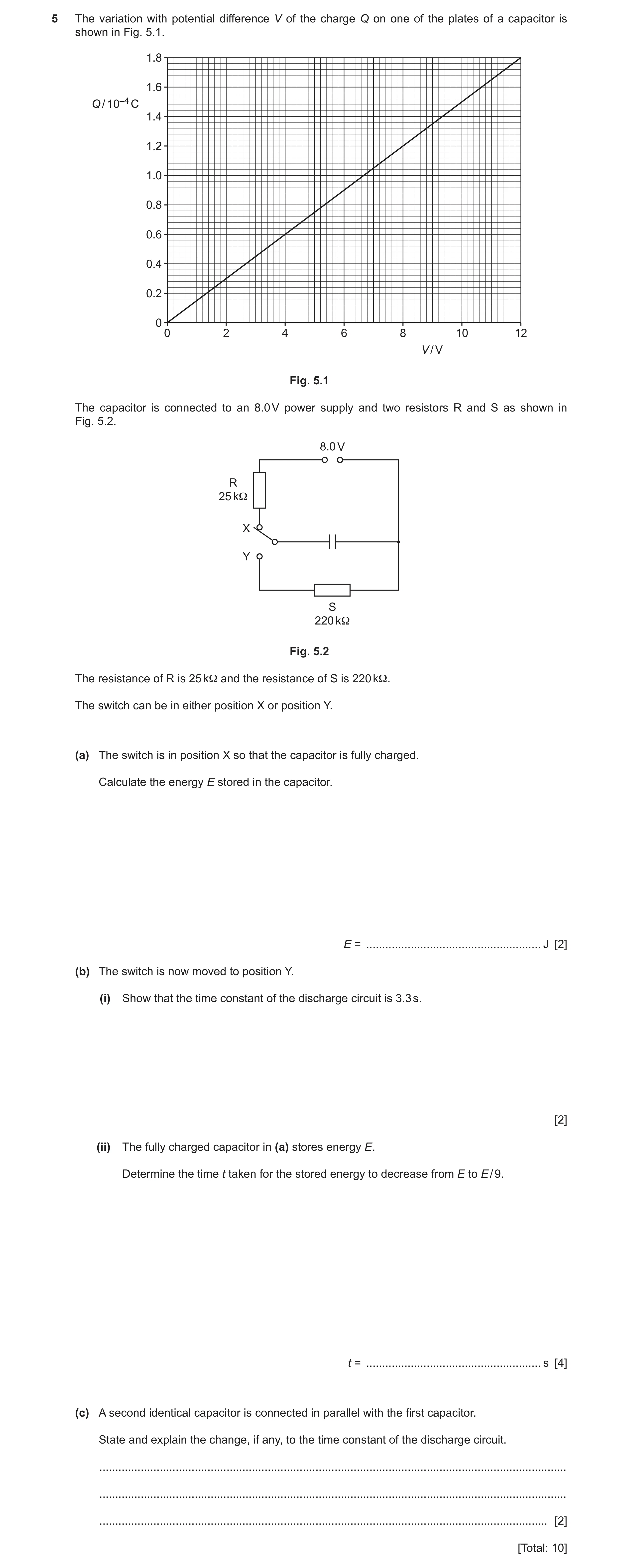
5 The variation with potential difference V of the charge Q on one of the plates of a capacitor is shown in Fig. 5.1. 1.8 1.6 Q / 10–4 C 1.4 1.2 1.0 0.8 0.6 0.4 0.2 0 0 2 4 6 8 10 12 V / V Fig. 5.1 The capacitor is connected to an 8.0 V power supply and two resistors R and S as shown in Fig. 5.2. 8.0 V R 25 kΩ X Y S 220 kΩ Fig. 5.2 The resistance of R is 25 kΩ and the resistance of S is 220 kΩ. The switch can be in either position X or position Y. (a) The switch is in position X so that the capacitor is fully charged. Calculate the energy E stored in the capacitor. E = … J [2] (b) The switch is now moved to position Y. (i) Show that the time constant of the discharge circuit is 3.3 s. [2] (ii) The fully charged capacitor in (a) stores energy E. Determine the time t taken for the stored energy to decrease from E to E / 9. t = … s [4] (c) A second identical capacitor is connected in parallel with the first capacitor. State and explain the change, if any, to the time constant of the discharge circuit. … … … [2] [Total: 10]
10 marks
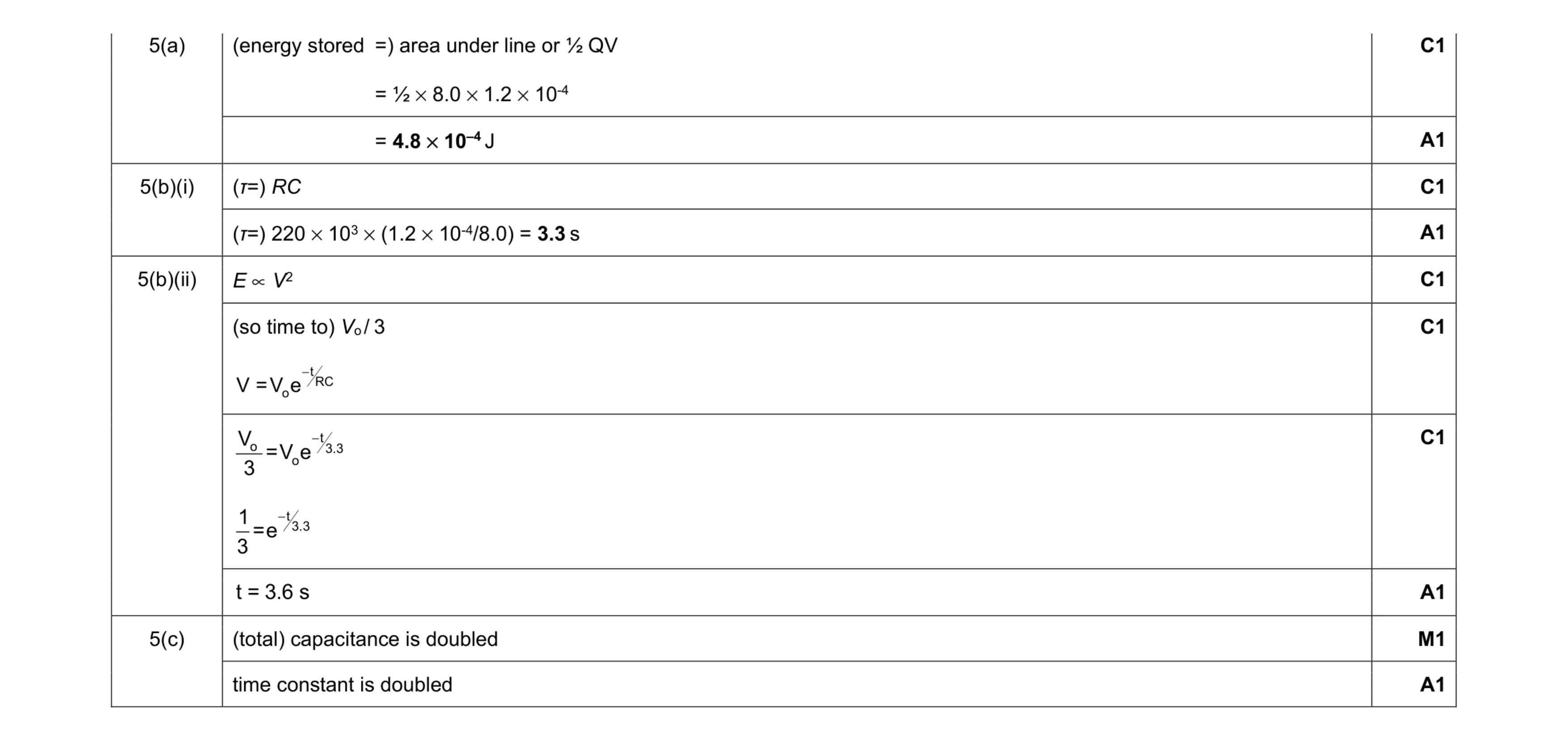
Mark scheme: 5(a) (energy stored =) area under line or ½ QV = ½ × 8.0 × 1.2 × 10-4 = 4.8 × 10⁻⁴ J A1 5(b)(i) (τ=) RC C1 (τ=) 220 × 103 × (1.2 × 10-4/8.0) = 3.3 s A1 5(b)(ii) E ∝ V2 C1 (so time to) Vo / 3 tRC o V = V e − C1 t o 3.3 o V = V e 3 − t3.3 1 = e 3 − C1 t = 3.6 s A1 5(c) (total) capacitance is doubled M1 time constant is doubled A1
This question in 9702/42 Feb/March 2022
Q2 · Define the capacitance of a parallel plate capacitor 9702/42 May/June 2022
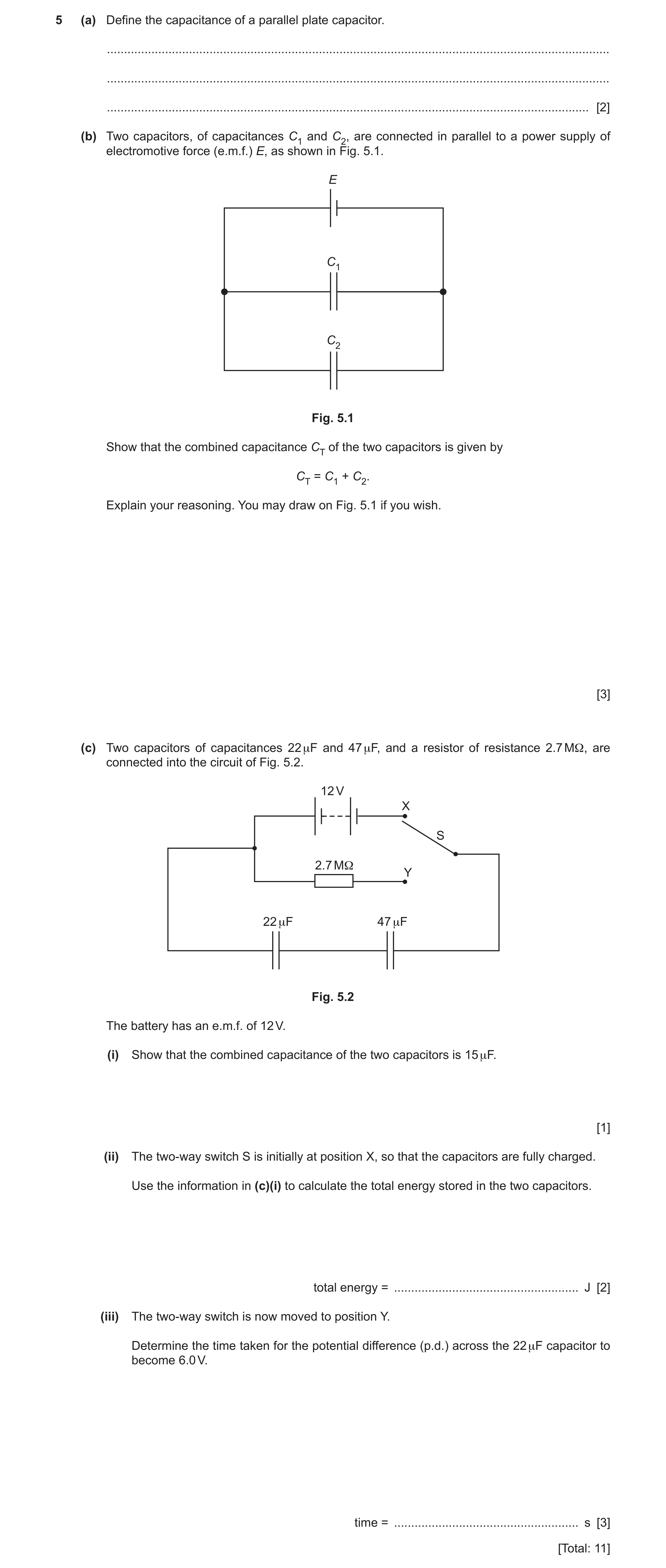
5 (a) Define the capacitance of a parallel plate capacitor. … … … [2] (b) Two capacitors, of capacitances C1 and C2, are connected in parallel to a power supply of electromotive force (e.m.f.) E, as shown in Fig. 5.1. E C1 C2 Fig. 5.1 Show that the combined capacitance CT of the two capacitors is given by CT = C1 + C2. Explain your reasoning. You may draw on Fig. 5.1 if you wish. [3] (c) Two capacitors of capacitances 22 μF and 47 μF, and a resistor of resistance 2.7 MΩ, are connected into the circuit of Fig. 5.2. 12 V X S 2.7 MΩ Y 22 μF 47 μF Fig. 5.2 The battery has an e.m.f. of 12 V. (i) Show that the combined capacitance of the two capacitors is 15 μF. [1] (ii) The two-way switch S is initially at position X, so that the capacitors are fully charged. Use the information in (c)(i) to calculate the total energy stored in the two capacitors. total energy = … J [2] (iii) The two-way switch is now moved to position Y. Determine the time taken for the potential difference (p.d.) across the 22 μF capacitor to become 6.0 V. time = … s [3] [Total: 11]
11 marks
Mark scheme: 5(a) charge / potential (difference) M1 charge is charge on one plate, and potential is p.d. across the plates A1 5(b) p.d. across both capacitors = E B1 QT = Q1 + Q2 B1 CTE = C1E + C2E hence CT = C1 + C2 B1 5(c)(i) [(1 / 22) + (1 / 47)]–1 = 15 F A1 5(c)(ii) energy = ½CV 2 C1 = ½ 15 10–6 122 = 1.1 10–3 J A1 5(c)(iii) initial p.d. (across 22 F) = 12 (15 / 22) = 8.2 V or final p.d. across both capacitors = 6.0 (22 / 15) = 8.8 V C1 V = V0 exp [– t / (2.7 106 15 10–6)] C1 6.0 = 8.2 exp [– t / (2.7 106 15 10–6)] or 8.8 = 12 exp [– t / (2.7 106 15 10–6)] t = 13 s A1
This question in 9702/42 May/June 2022
Q3 · A capacitor of capacitance C and a resistor of resistance R are connected as shown in Fig 9702/42 Oct/Nov 2022
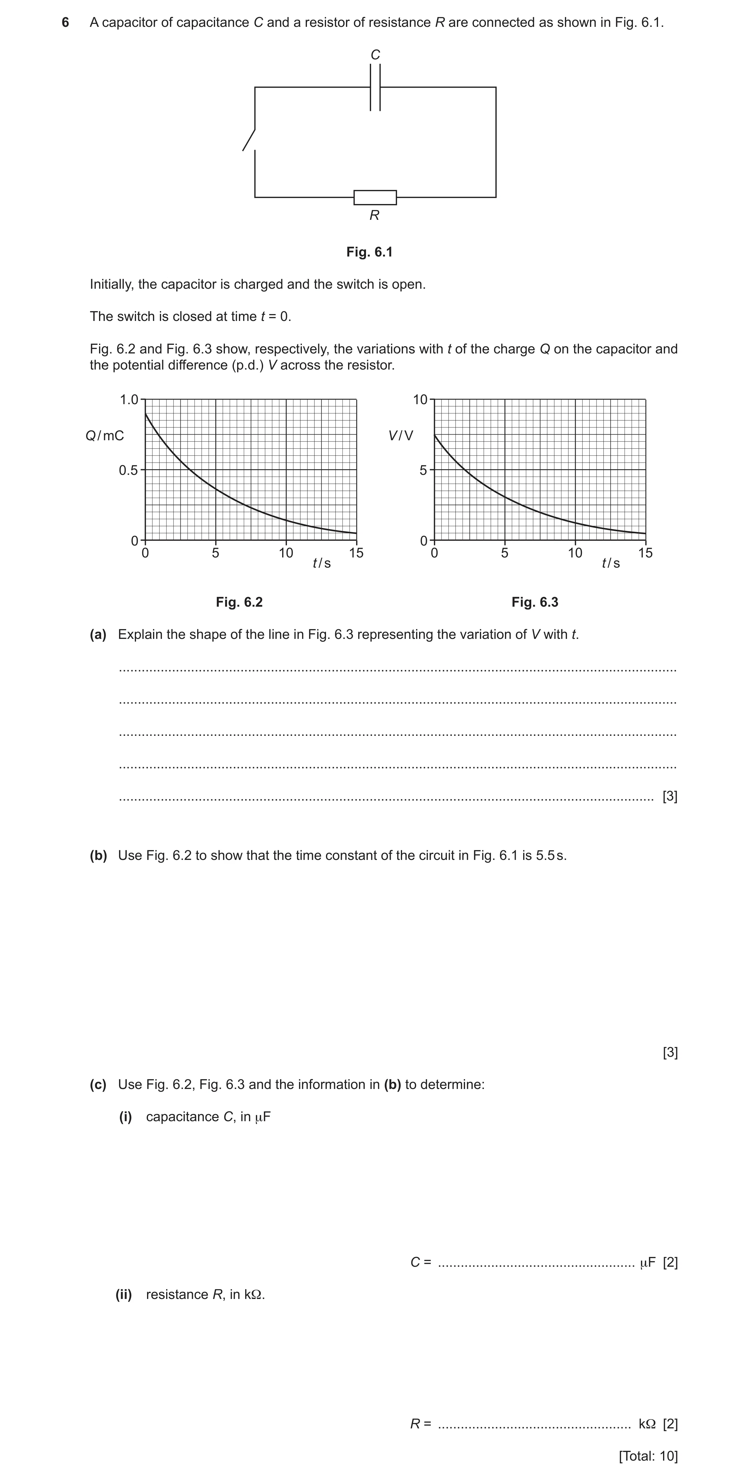
6 A capacitor of capacitance C and a resistor of resistance R are connected as shown in Fig. 6.1. C R Fig. 6.1 Initially, the capacitor is charged and the switch is open. The switch is closed at time t = 0. Fig. 6.2 and Fig. 6.3 show, respectively, the variations with t of the charge Q on the capacitor and the potential difference (p.d.) V across the resistor. 1.0 10 Q / mC V / V 0.5 5 0 0 0 5 10 15 0 5 10 15 t / s t / s Fig. 6.2 Fig. 6.3 (a) Explain the shape of the line in Fig. 6.3 representing the variation of V with t. … … … … … [3] (b) Use Fig. 6.2 to show that the time constant of the circuit in Fig. 6.1 is 5.5 s. [3] (c) Use Fig. 6.2, Fig. 6.3 and the information in (b) to determine: (i) capacitance C, in μF C = … μF [2] (ii) resistance R, in kΩ. R = … kΩ [2] [Total: 10]
10 marks
Mark scheme: 6(a) • p.d. across resistor = p.d. across capacitor B2 • current (in resistor) proportional to p.d. across it • current causes capacitor to lose charge • charge (on capacitor) proportional to p.d. so p.d. decreases Any two points, 1 mark each rate of change of p.d. decreases as p.d. decreases B1 6(b) Q0 = 0.90 mC and at t = one time constant, Q = Q0 exp (–1) B1 at t = one time constant, Q = 0.90 exp (–1) = 0.33 mC M1 evidence of graph reading: when Q = 0.33 mC, t = 5.5 s A1 or evidence of two correct sets of readings for Q and t from the graph (B1) correct substitution of Q and t values into Q2 = Q1 exp [(t1 – t2) / ] (M1) calculation to give = 5.5 s (A1) or read-off of half-life as 3.75 s (B1) use of Q = Q0 exp (–t / ) to show that = half-life / ln 2 (M1) = 3.75 / ln 2 = 5.4 s (A1) 6(b) or tangent drawn on Q–t graph and value of Q at exact same time as tangent read from graph (M1) gradient of tangent correctly calculated (A1) = Q / gradient used to correctly calculate a value for as 5.5 s (A1) 6(c)(i) C = Q / V C1 = [(0.90 10–3) / 7.5] = 1.2 10–4 C A1 = 120 F 6(c)(ii) R = τ / C C1 = 5.5 / (1.2 10–4) (= 45 800 ) A1 = 46 k
This question in 9702/42 Oct/Nov 2022
Q4 · A capacitor, a battery of electromotive force (e.m.f.) 12 V, a resistor R and a two-way… 9702/42 Feb/March 2023
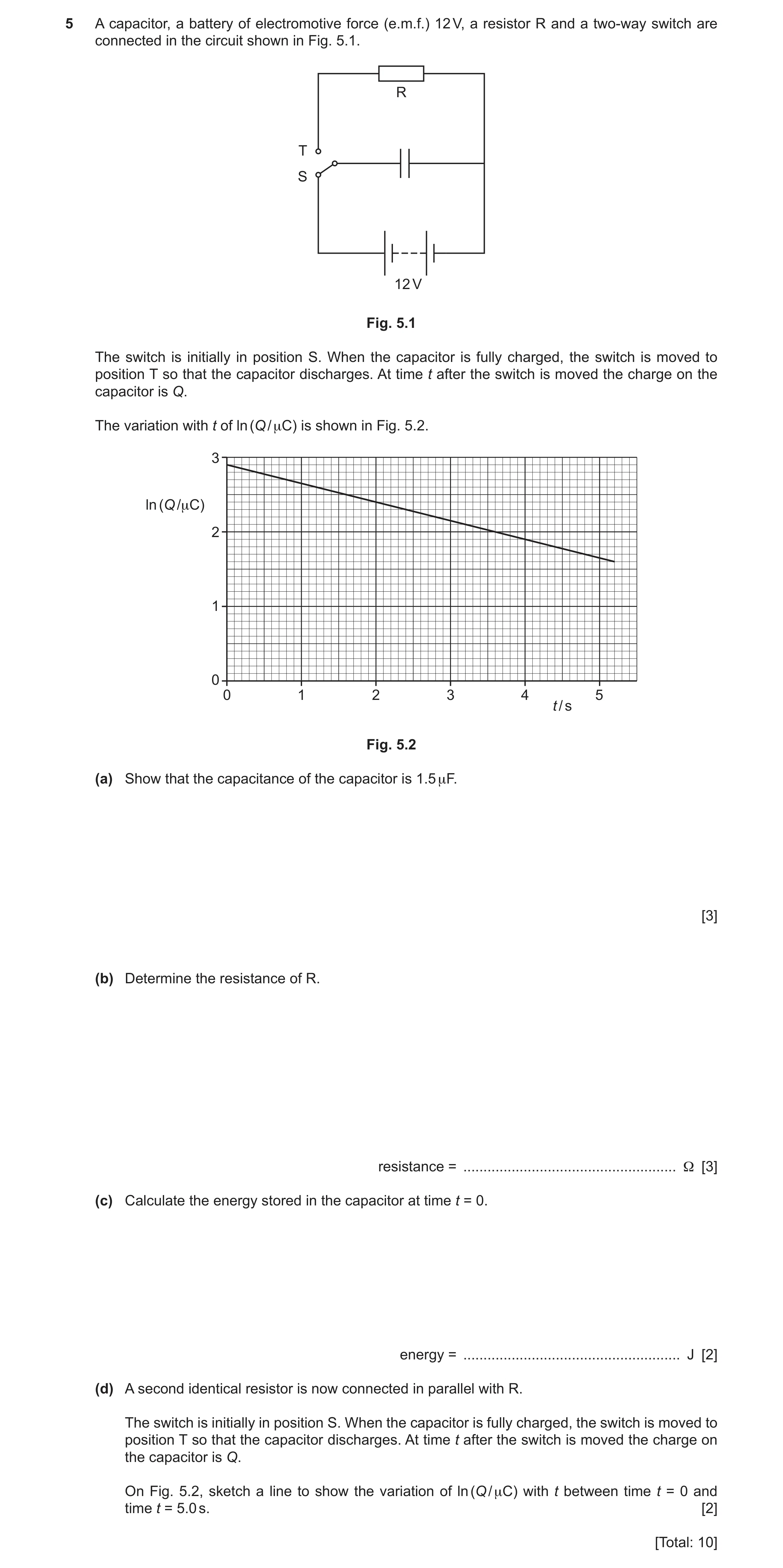
5 A capacitor, a battery of electromotive force (e.m.f.) 12 V, a resistor R and a two-way switch are connected in the circuit shown in Fig. 5.1. R T S 12 V Fig. 5.1 The switch is initially in position S. When the capacitor is fully charged, the switch is moved to position T so that the capacitor discharges. At time t after the switch is moved the charge on the capacitor is Q. The variation with t of ln (Q / μC) is shown in Fig. 5.2. 3 ln (Q /μC) 2 1 0 0 1 2 3 4 5 t / s Fig. 5.2 (a) Show that the capacitance of the capacitor is 1.5 μF. [3] (b) Determine the resistance of R. resistance = … Ω [3] (c) Calculate the energy stored in the capacitor at time t = 0. energy = … J [2] (d) A second identical resistor is now connected in parallel with R. The switch is initially in position S. When the capacitor is fully charged, the switch is moved to position T so that the capacitor discharges. At time t after the switch is moved the charge on the capacitor is Q. On Fig. 5.2, sketch a line to show the variation of ln (Q / μC) with t between time t = 0 and time t = 5.0 s. [2] [Total: 10]
10 marks
Mark scheme: 5(a) from graph ln Q = 2.9 B1 (so Q = 18.2 C) C = Q / V C1 = 18.2 / 12 = 1.5 F A1 5(b) gradient = –0.25 C1 gradient = –1 / RC C1 R = 1 / (0.25 1.5 10–6) A1 = 2.7 106 Q − tCR − t (C1) or = e or ln Q – ln Q0 = Q0 CR −5.2 −6 (C1) 4.95 (1.5 10 R ) e.g. = e or 1.6 – 2.9 = 5.2 / (1.5 × 10⁻⁶R) 18.2 R = 2.7 106 (A1) 5(c) W = ½ QV C1 = ½ 18.2 10–6 12 A1 = 1.1 10–4 J or W = ½ CV2 (C1) = ½ 1.5 10–6 122 (A1) = 1.1 10–4 J or W = ½ Q2 / C (C1) = ½ (18.2 10–6)2 / 1.5 10–6 (A1) = 1.1 10–4 J 5(d) straight line with different negative gradient starting from (0, 2.9) M1 straight line between t = 0 and at least t = 5.0 s with twice the gradient of the original line A1
This question in 9702/42 Feb/March 2023
Q5 · A capacitor of capacitance C connected in series with a resistor of resistance R 9702/41 May/June 2024
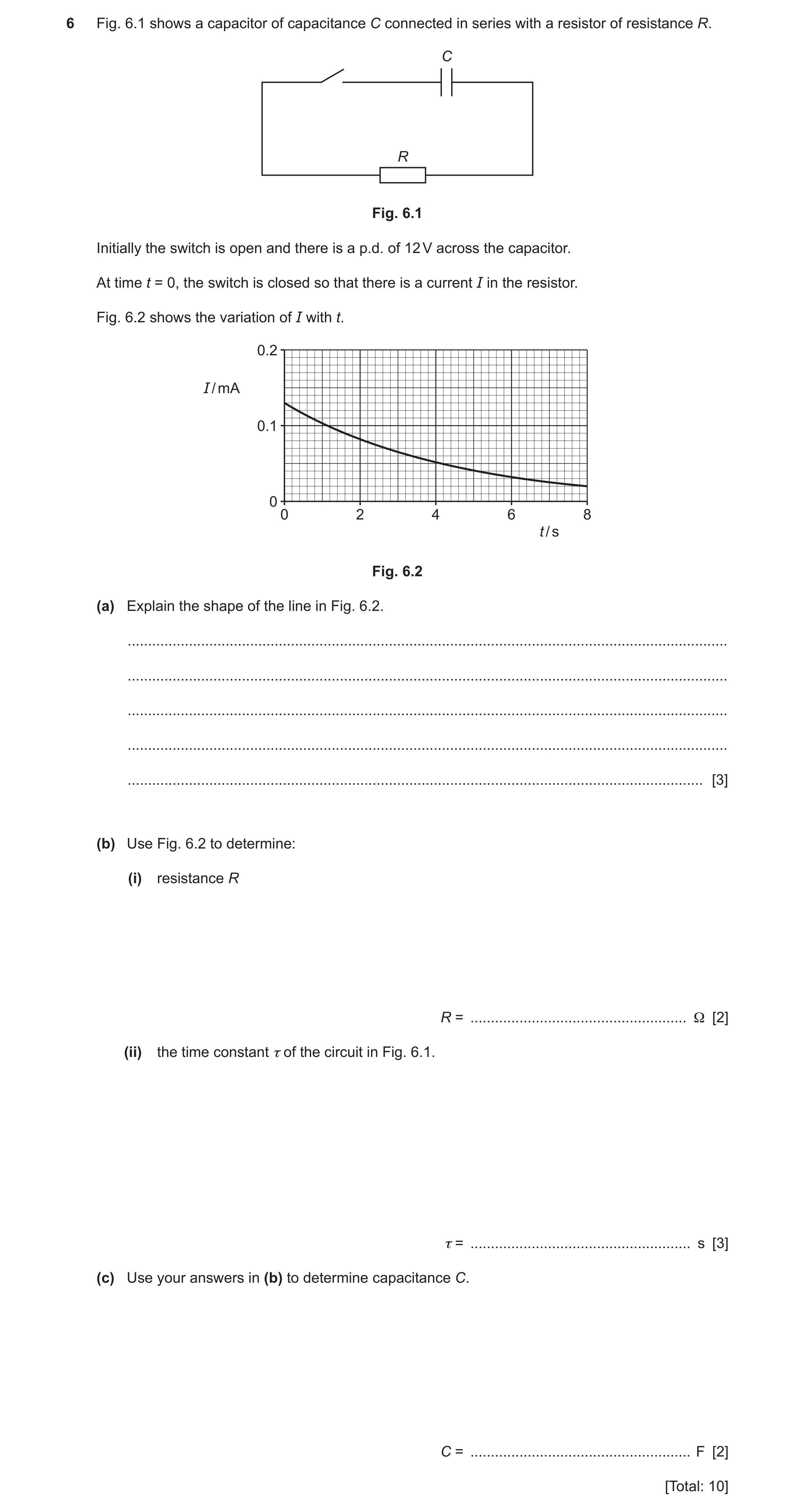
6 Fig. 6.1 shows a capacitor of capacitance C connected in series with a resistor of resistance R. C R Fig. 6.1 Initially the switch is open and there is a p.d. of 12 V across the capacitor. At time t = 0, the switch is closed so that there is a current I in the resistor. Fig. 6.2 shows the variation of I with t. 0.2 I / mA 0.1 0 0 2 4 6 8 t / s Fig. 6.2 (a) Explain the shape of the line in Fig. 6.2. … … … … … [3] (b) Use Fig. 6.2 to determine: (i) resistance R R = … Ω [2] (ii) the time constant τ of the circuit in Fig. 6.1. τ = … s [3] (c) Use your answers in (b) to determine capacitance C. C = … F [2] [Total: 10]
10 marks
Mark scheme: 6(a) p.d. across capacitor proportional to charge on capacitor p.d. across capacitor = p.d. across resistor current in resistor proportional to p.d. across resistor current in resistor = rate of decrease of charge on capacitor Any two points, 1 mark each B2 charge proportional to current so rate of decrease of current decreases as current decreases (therefore exponential shape) B1 6(b)(i) R = V / I = 12 / (0.13 10–3) C1 = 9.2 104 A1 6(b)(ii) correct read-off of at least one pair of values for I and t C1 attempted read-off of t when I = 0.048 mA or substitution of a correct pair of values of I and t into I = 0.13 exp (– t / ) C1 = 4.3 s A1 6(c) = RC C1 C = / R = 4.3 / (9.2 104) = 4.7 10–5 F A1
This question in 9702/41 May/June 2024
Q6 · A capacitor of capacitance C connected in series with a resistor of resistance R 9702/43 May/June 2024
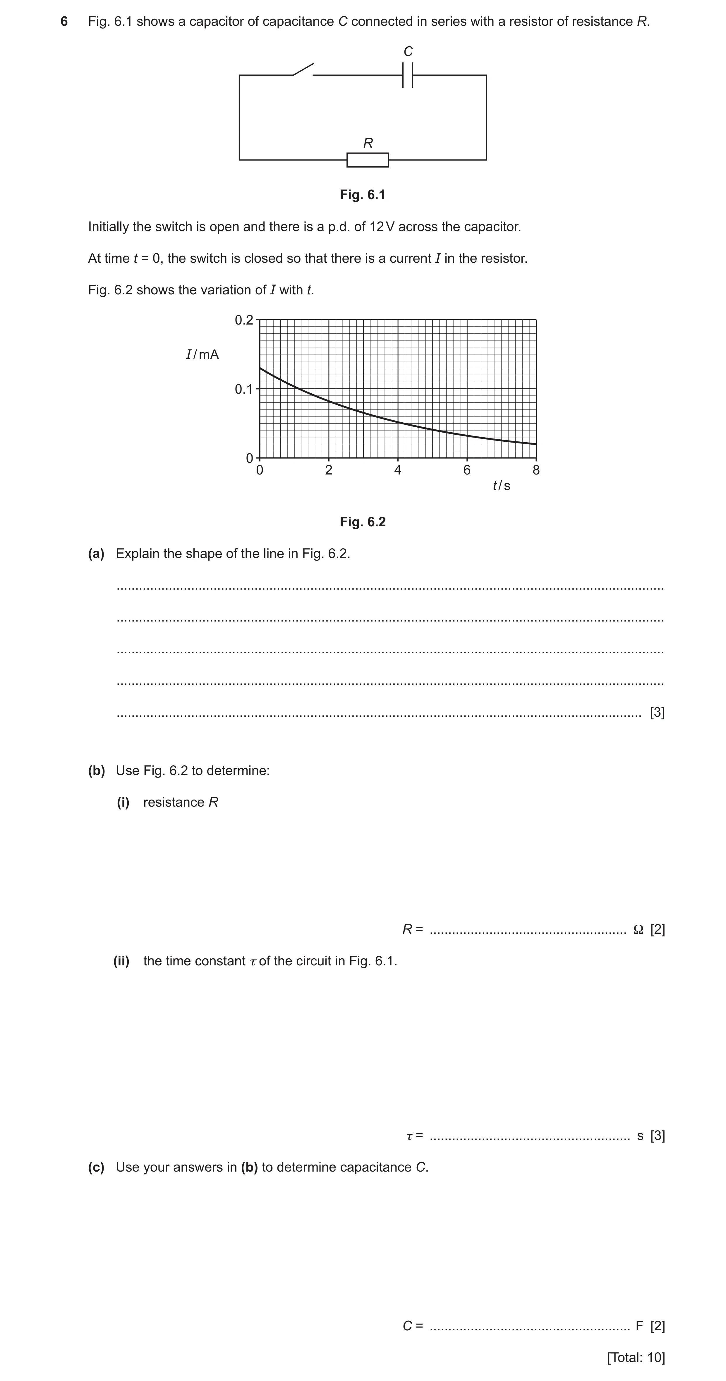
6 Fig. 6.1 shows a capacitor of capacitance C connected in series with a resistor of resistance R. C R Fig. 6.1 Initially the switch is open and there is a p.d. of 12 V across the capacitor. At time t = 0, the switch is closed so that there is a current I in the resistor. Fig. 6.2 shows the variation of I with t. 0.2 I / mA 0.1 0 0 2 4 6 8 t / s Fig. 6.2 (a) Explain the shape of the line in Fig. 6.2. … … … … … [3] (b) Use Fig. 6.2 to determine: (i) resistance R R = … Ω [2] (ii) the time constant τ of the circuit in Fig. 6.1. τ = … s [3] (c) Use your answers in (b) to determine capacitance C. C = … F [2] [Total: 10]
10 marks
Mark scheme: 6(a) p.d. across capacitor proportional to charge on capacitor p.d. across capacitor = p.d. across resistor current in resistor proportional to p.d. across resistor current in resistor = rate of decrease of charge on capacitor Any two points, 1 mark each B2 charge proportional to current so rate of decrease of current decreases as current decreases (therefore exponential shape) B1 6(b)(i) R = V / I = 12 / (0.13 10–3) C1 = 9.2 104 A1 6(b)(ii) correct read-off of at least one pair of values for I and t C1 attempted read-off of t when I = 0.048 mA or substitution of a correct pair of values of I and t into I = 0.13 exp (– t / ) C1 = 4.3 s A1 6(c) = RC C1 C = / R = 4.3 / (9.2 104) = 4.7 10–5 F A1
This question in 9702/43 May/June 2024
Q7 · A capacitor of capacitance C1 is connected in series with a second capacitor of… 9702/42 Feb/March 2025
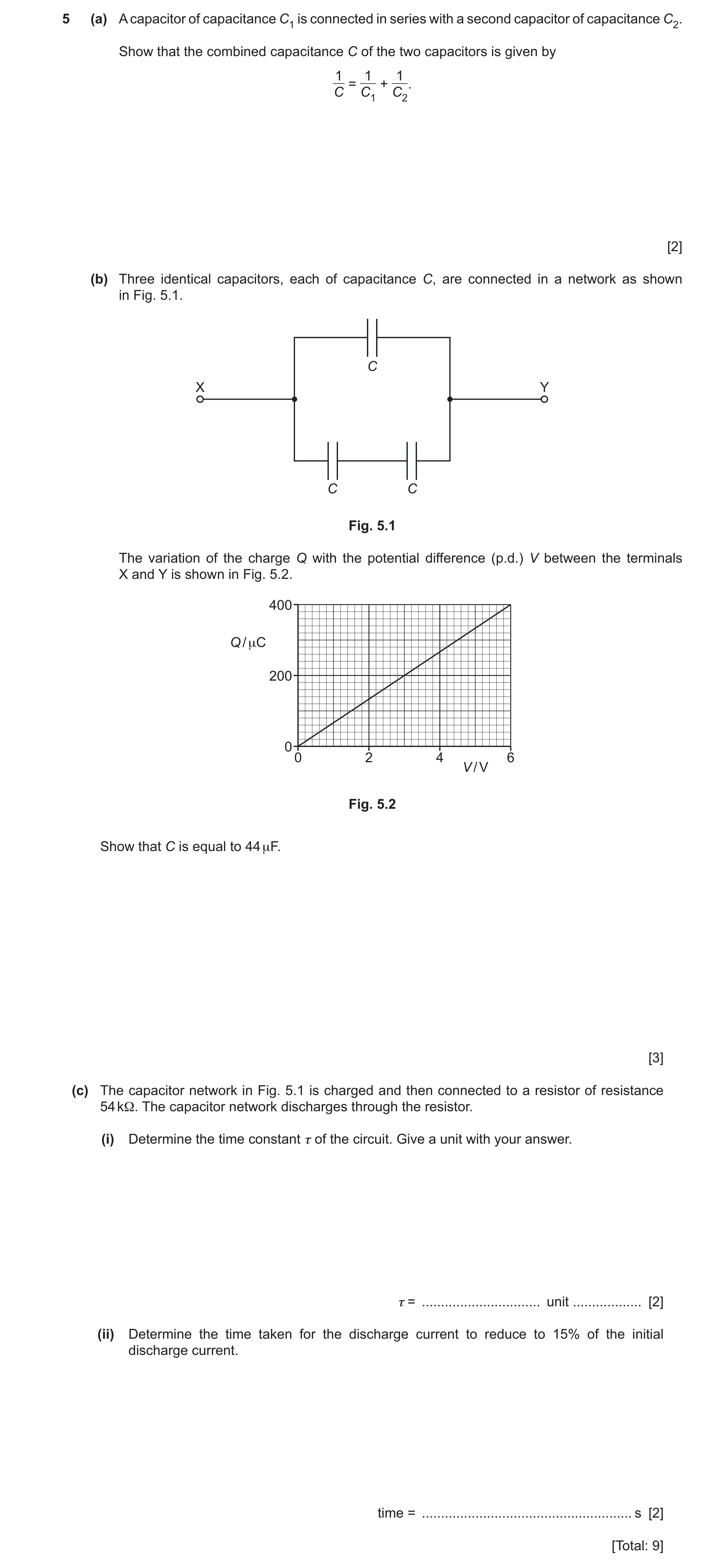
5 (a) A capacitor of capacitance C1 is connected in series with a second capacitor of capacitance C2. Show that the combined capacitance C of the two capacitors is given by 1 1 1 = + . C C1 C2 [2] (b) Three identical capacitors, each of capacitance C, are connected in a network as shown in Fig. 5.1. C X Y C C Fig. 5.1 The variation of the charge Q with the potential difference (p.d.) V between the terminals X and Y is shown in Fig. 5.2. 400 Q / μC 200 0 0 2 4 6 V / V Fig. 5.2 Show that C is equal to 44 µF. [3] (c) The capacitor network in Fig. 5.1 is charged and then connected to a resistor of resistance 54 kΩ. The capacitor network discharges through the resistor. (i) Determine the time constant τ of the circuit. Give a unit with your answer. τ = … unit … [2] (ii) Determine the time taken for the discharge current to reduce to 15% of the initial discharge current. time = … s [2] [Total: 9]
9 marks
Mark scheme: 5(a) Q = Q1 = Q2 and V = V1 + V2 M1 V = Q / C so: A1 Q / C = Q / C1 + Q / C2 leading to 1 / C = 1 / C1 + 1 / C2 5(b) total capacitance = C + ½C = (3 / 2)C C1 total capacitance = gradient C1 = 400 10–6 / 6.0 either: C = (2 400 10–6) / (3 6.0) = 4.4 10–5 F = 44 F A1 or: C = (2 400) / (3 6.0) = 44 F 5(c)(i) τ = RC C1 = 54 103 (3/2) 44 10–6 A1 = 3.6 s 5(c)(ii) 0.15 = exp(–t / 3.6) C1 t = 6.8 s A1
This question in 9702/42 Feb/March 2025
Q8 · A circuit that rectifies an alternating input voltage VIN and produces an output voltage… 9702/41 May/June 2025
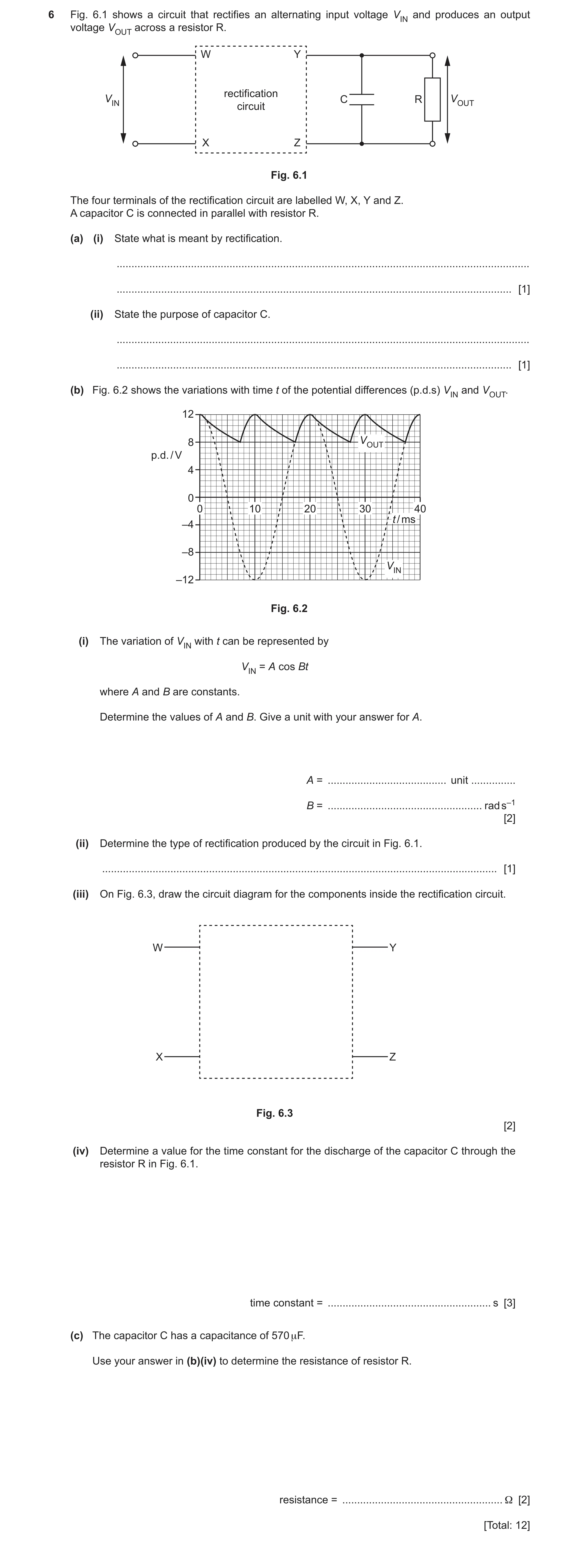
6 Fig. 6.1 shows a circuit that rectifies an alternating input voltage VIN and produces an output voltage VOUT across a resistor R. W Y rectification VIN C R VOUT circuit X Z Fig. 6.1 The four terminals of the rectification circuit are labelled W, X, Y and Z. A capacitor C is connected in parallel with resistor R. (a) (i) State what is meant by rectification. … … [1] (ii) State the purpose of capacitor C. … … [1] (b) Fig. 6.2 shows the variations with time t of the potential differences (p.d.s) VIN and VOUT. 12 8 VOUT p.d. / V 4 0 0 10 20 30 40 t / ms –4 –8 VIN –12 Fig. 6.2 (i) The variation of VIN with t can be represented by VIN = A cos Bt where A and B are constants. Determine the values of A and B. Give a unit with your answer for A. A = … unit … B = … rad s–1 [2] (ii) Determine the type of rectification produced by the circuit in Fig. 6.1. … [1] (iii) On Fig. 6.3, draw the circuit diagram for the components inside the rectification circuit. W Y X Z Fig. 6.3 [2] (iv) Determine a value for the time constant for the discharge of the capacitor C through the resistor R in Fig. 6.1. time constant = … s [3] (c) The capacitor C has a capacitance of 570 μF. Use your answer in (b)(iv) to determine the resistance of resistor R. resistance = … Ω [2] [Total: 12]
12 marks
Mark scheme: 6(a)(i) conversion from a.c. to d.c. B1 6(a)(ii) smoothing B1 6(b)(i) A = 12 V A1 B = 2 / (20 × 10–3) A1 = 310 rad s–1 6(b)(ii) full-wave (rectification) B1 6(b)(iii) four diodes shown, with correct circuit symbols B1 four diodes correctly connected to form a bridge rectifier B1 6(b)(iv) V = V0 exp (–t / ) C1 or V = V0 exp (–t / RC) and = RC 8.0 = 12 exp (– 7.3 × 10⁻³ / ) C1 = 0.018 s A1 6(c) time constant = RC C1 R = (0.018 / 570 × 10–6) A1 = 32
This question in 9702/41 May/June 2025
Q9 · A circuit containing a capacitor of capacitance C and a resistor of resistance R 9702/42 May/June 2025
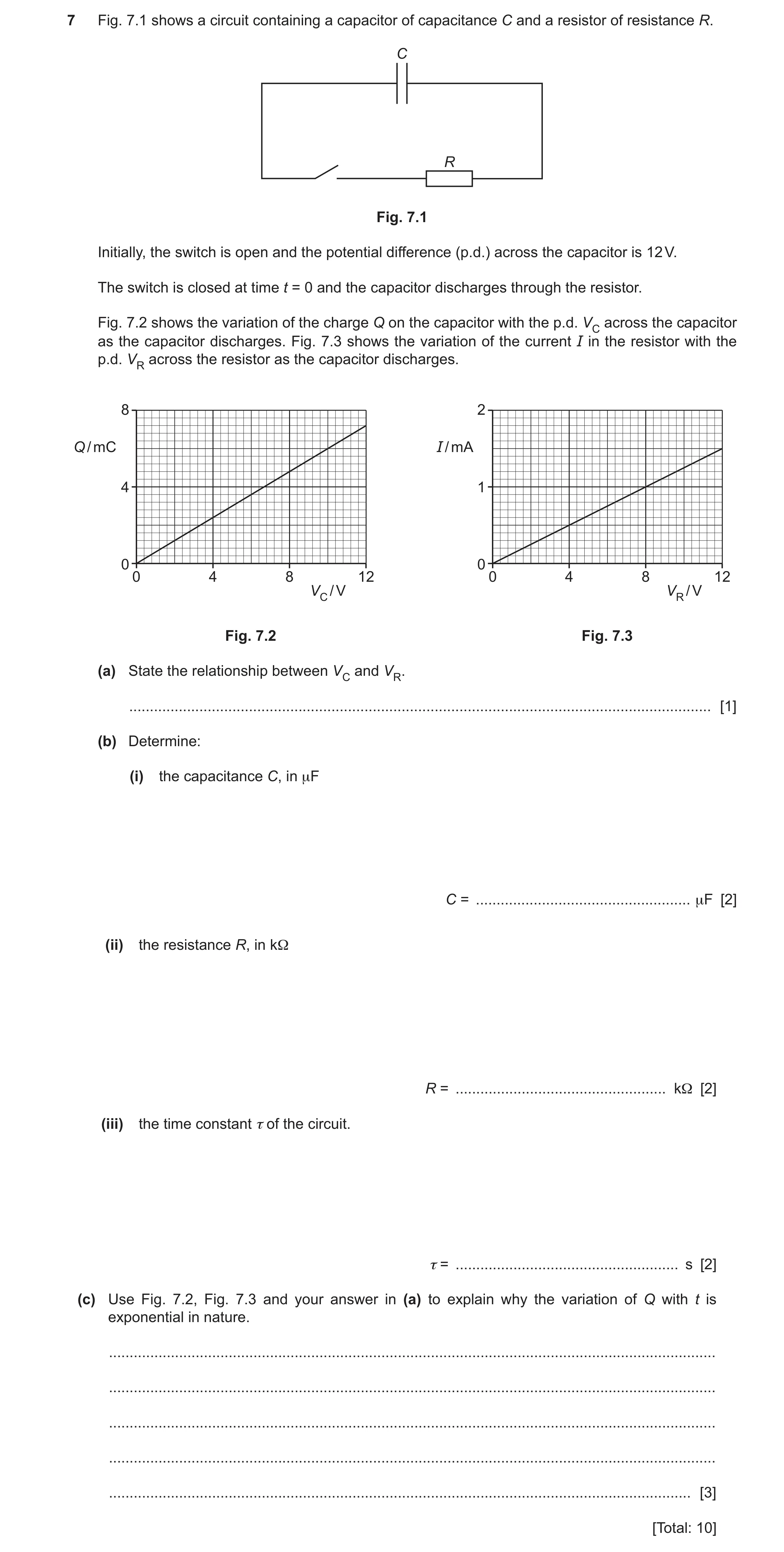
7 Fig. 7.1 shows a circuit containing a capacitor of capacitance C and a resistor of resistance R. C R Fig. 7.1 Initially, the switch is open and the potential difference (p.d.) across the capacitor is 12 V. The switch is closed at time t = 0 and the capacitor discharges through the resistor. Fig. 7.2 shows the variation of the charge Q on the capacitor with the p.d. VC across the capacitor as the capacitor discharges. Fig. 7.3 shows the variation of the current I in the resistor with the p.d. VR across the resistor as the capacitor discharges. 8 2 Q / mC I / mA 4 1 0 0 0 4 8 12 0 4 8 12 VC / V VR / V Fig. 7.2 Fig. 7.3 (a) State the relationship between VC and VR. … [1] (b) Determine: (i) the capacitance C, in μF C = … μF [2] (ii) the resistance R, in kΩ R = … kΩ [2] (iii) the time constant τ of the circuit. τ = … s [2] (c) Use Fig. 7.2, Fig. 7.3 and your answer in (a) to explain why the variation of Q with t is exponential in nature. … … … … … [3] [Total: 10]
10 marks
Mark scheme: 7(a) VC = VR B1 7(b)(i) C = Q / V C1 = (7.2 × 10⁻³) / 12 (= 6.0 × 10⁻⁴ F) A1 = 600 F 7(b)(ii) R = V / I C1 = 12 / (1.5 × 10⁻³) (= 8000 ) A1 = 8.0 k 7(b)(iii) = RC C1 = 8000 × 6.0 × 10–4 A1 = 4.8 s 7(c) Any two points from: B2 • charge and current are both (directly) proportional to voltage • charge is (directly) proportional to current • current is the rate of change of charge Q is proportional to the rate of change of Q (so exponential variation) B1
This question in 9702/42 May/June 2025
Q10 · Define electric field at a point 9702/42 Oct/Nov 2025
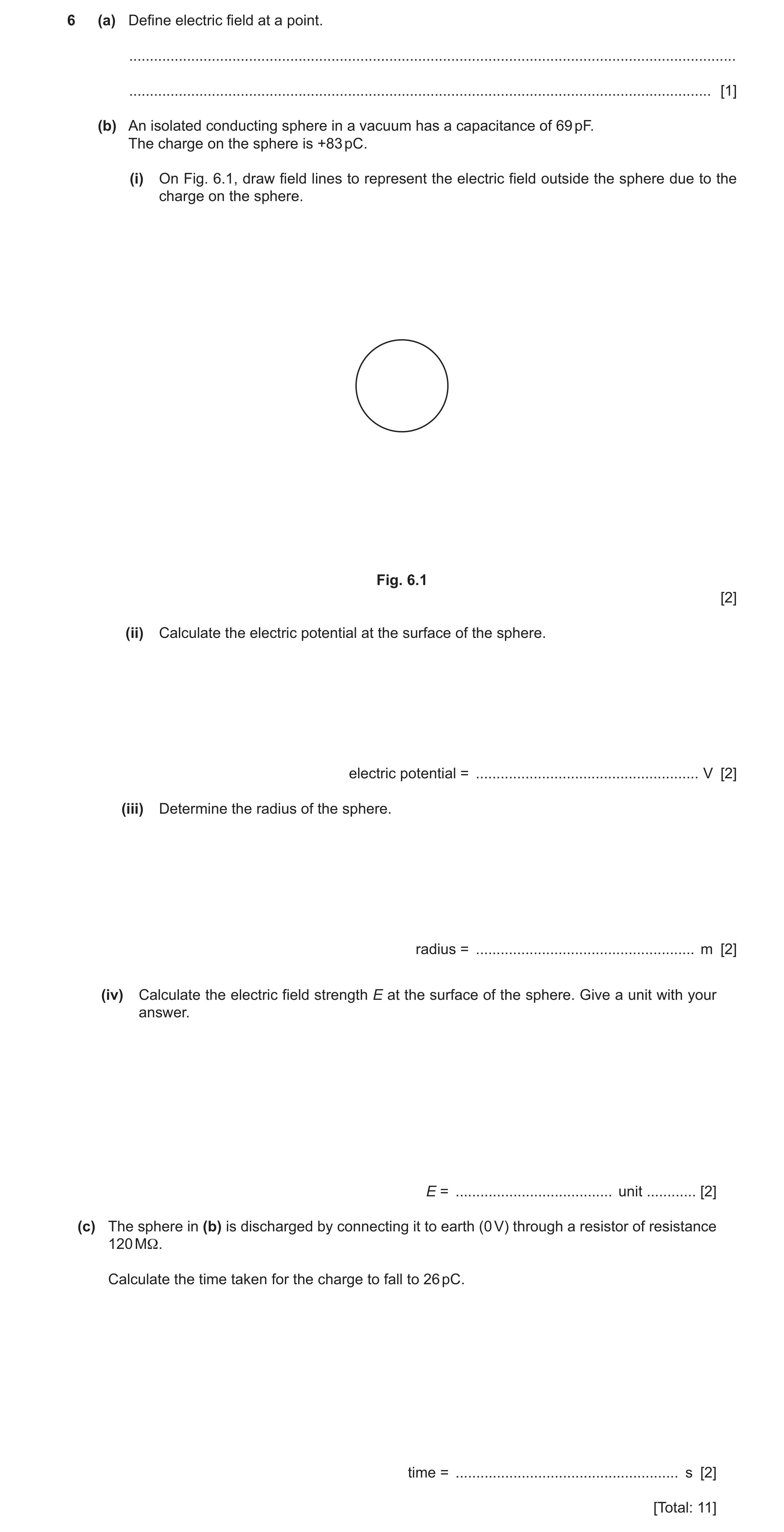
6 (a) Define electric field at a point. … … [1] (b) An isolated conducting sphere in a vacuum has a capacitance of 69 pF. The charge on the sphere is +83 pC. (i) On Fig. 6.1, draw field lines to represent the electric field outside the sphere due to the charge on the sphere. Fig. 6.1 [2] (ii) Calculate the electric potential at the surface of the sphere. electric potential = … V [2] (iii) Determine the radius of the sphere. radius = … m [2] (iv) Calculate the electric field strength E at the surface of the sphere. Give a unit with your answer. E = … unit … [2] (c) The sphere in (b) is discharged by connecting it to earth (0 V) through a resistor of resistance 120 MΩ. Calculate the time taken for the charge to fall to 26 pC. time = … s [2] [Total: 11]
11 marks
Mark scheme: 6(a) force per unit positive charge B1 6(b)(i) radial lines B1 arrows pointing away from the sphere B1 6(b)(ii) C = Q / V C1 V = 83 / 69 A1 = (+)1.2 V 6(b)(iii) V = Q / 4ε0r C1 r = (83 10–12) / (4 8.85 10–12 1.2) = 0.62 m A1 6(b)(iv) E = Q / 4ε0r2 C1 = (83 10–12) / (4 8.85 10–12 0.622) A1 = 1.9 N C–1 6(c) 26 = 83 exp [– t / (120 106 69 10–12)] C1 t = 9.6 10–3 s A1
This question in 9702/42 Oct/Nov 2025
 10
10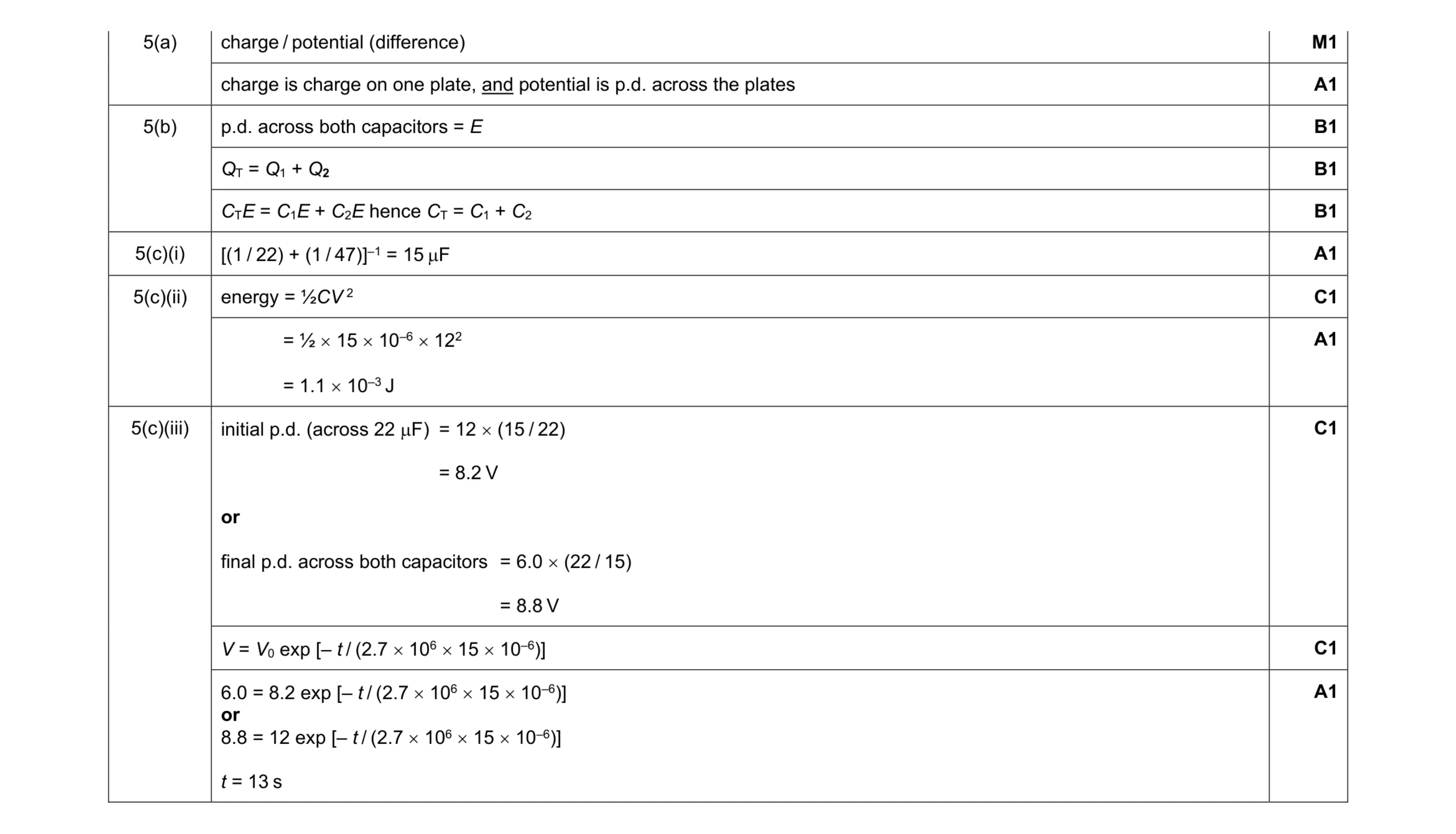 11
11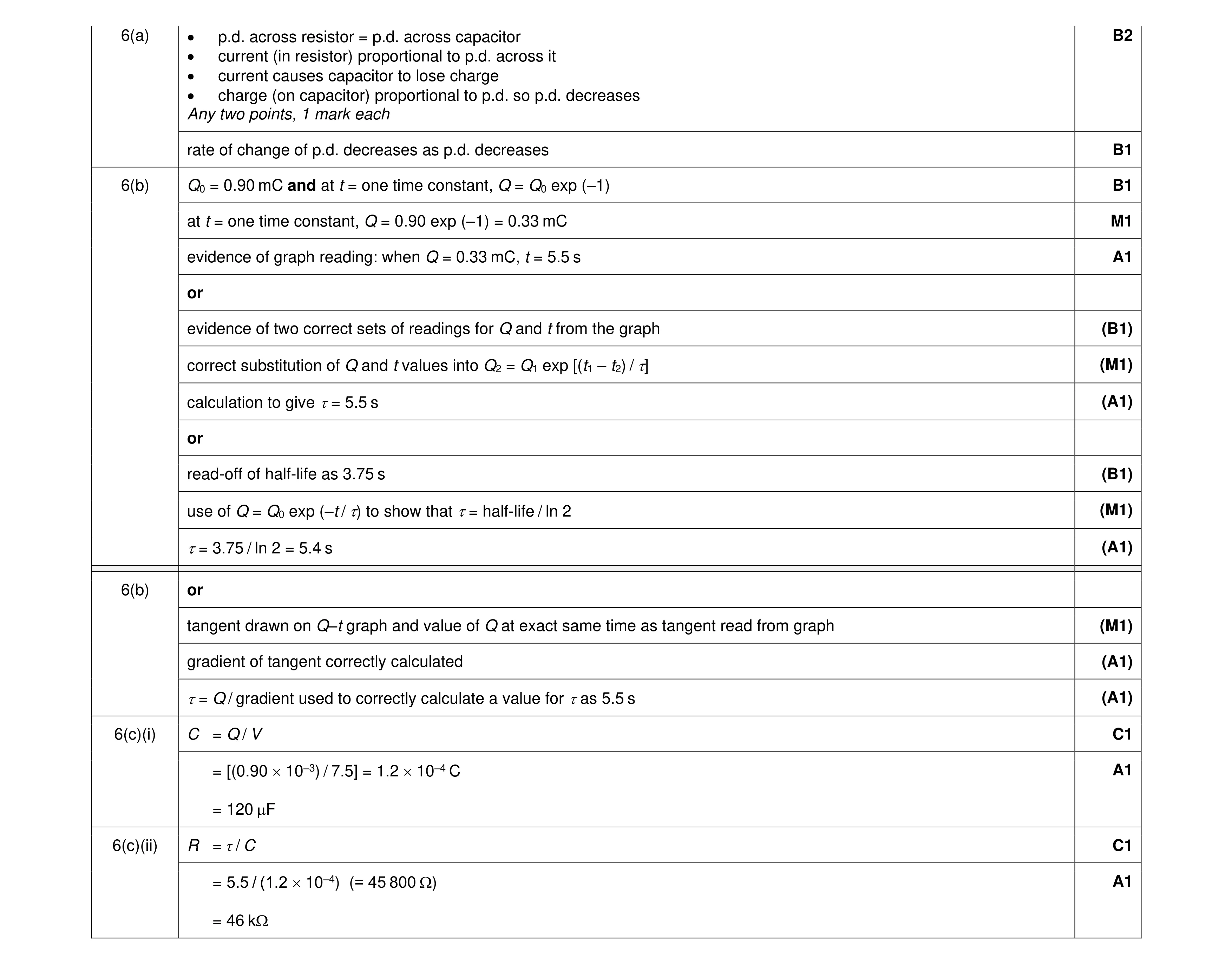 10
10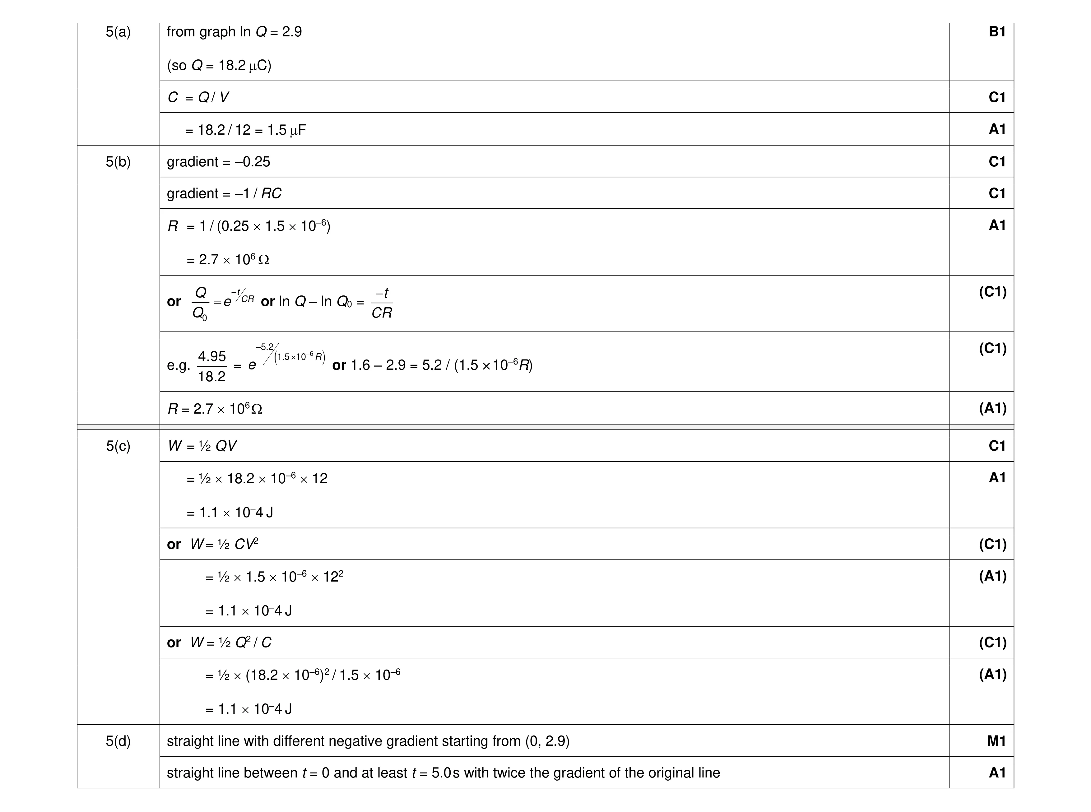 10
10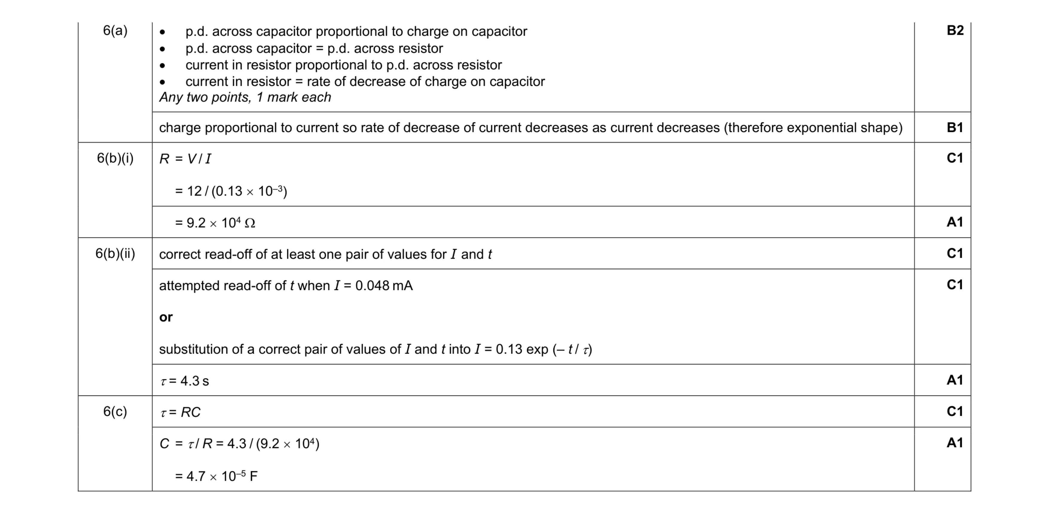 10
10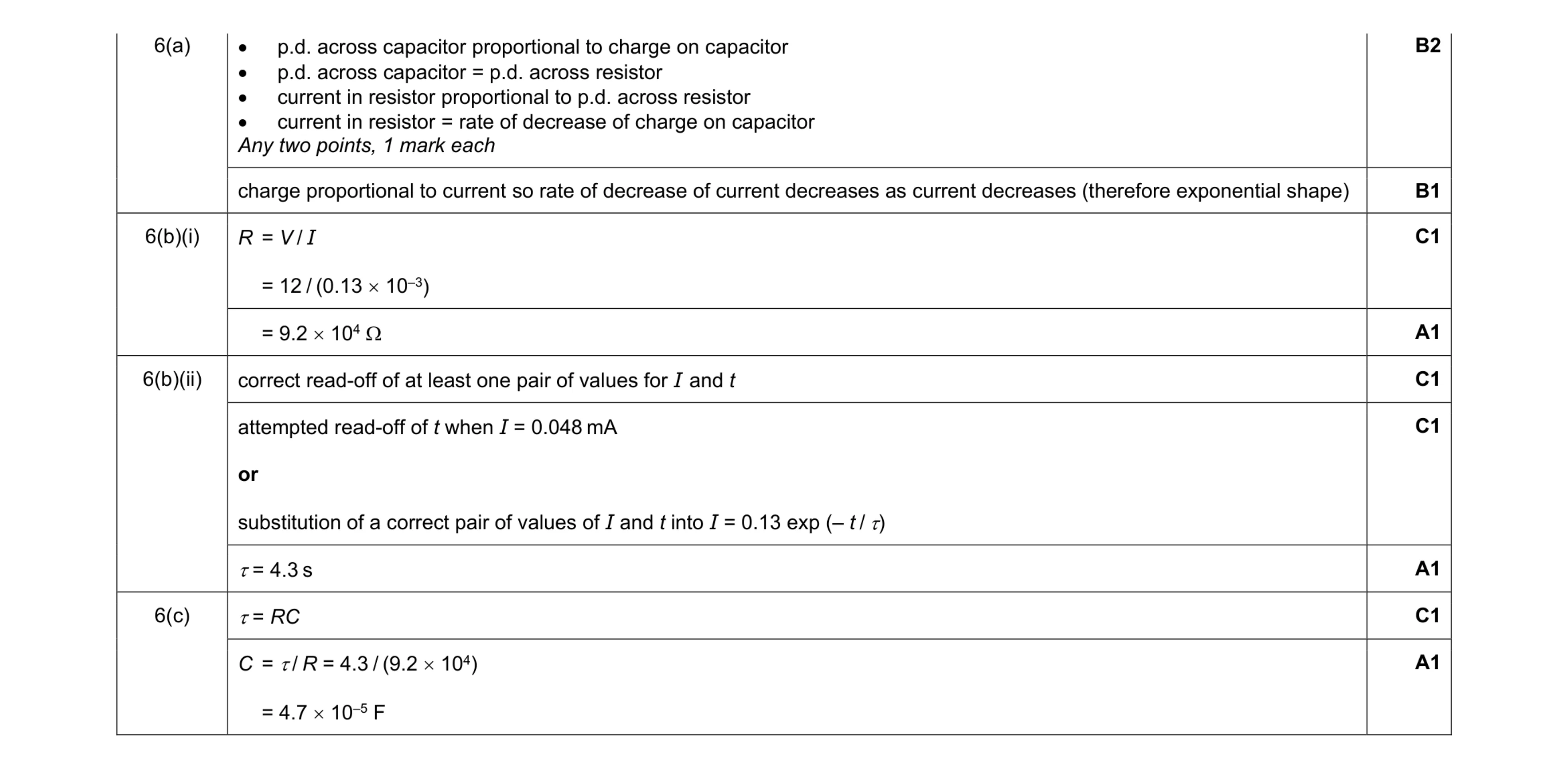 10
10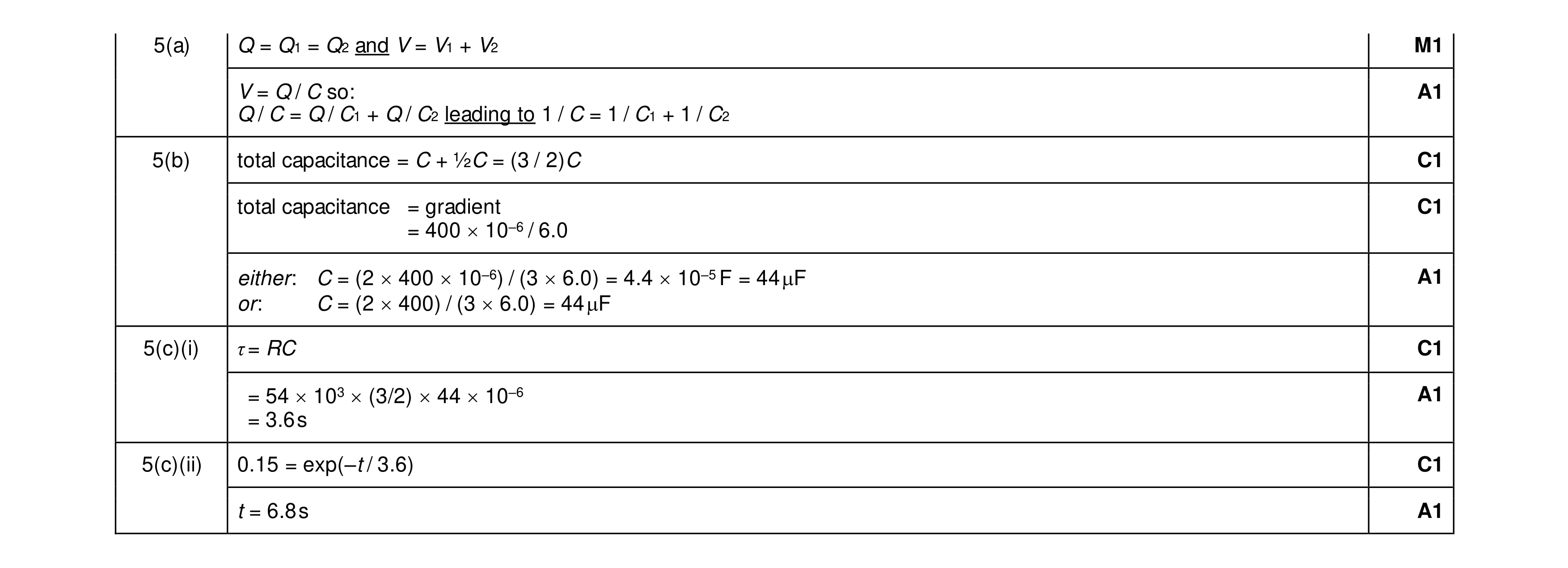 9
9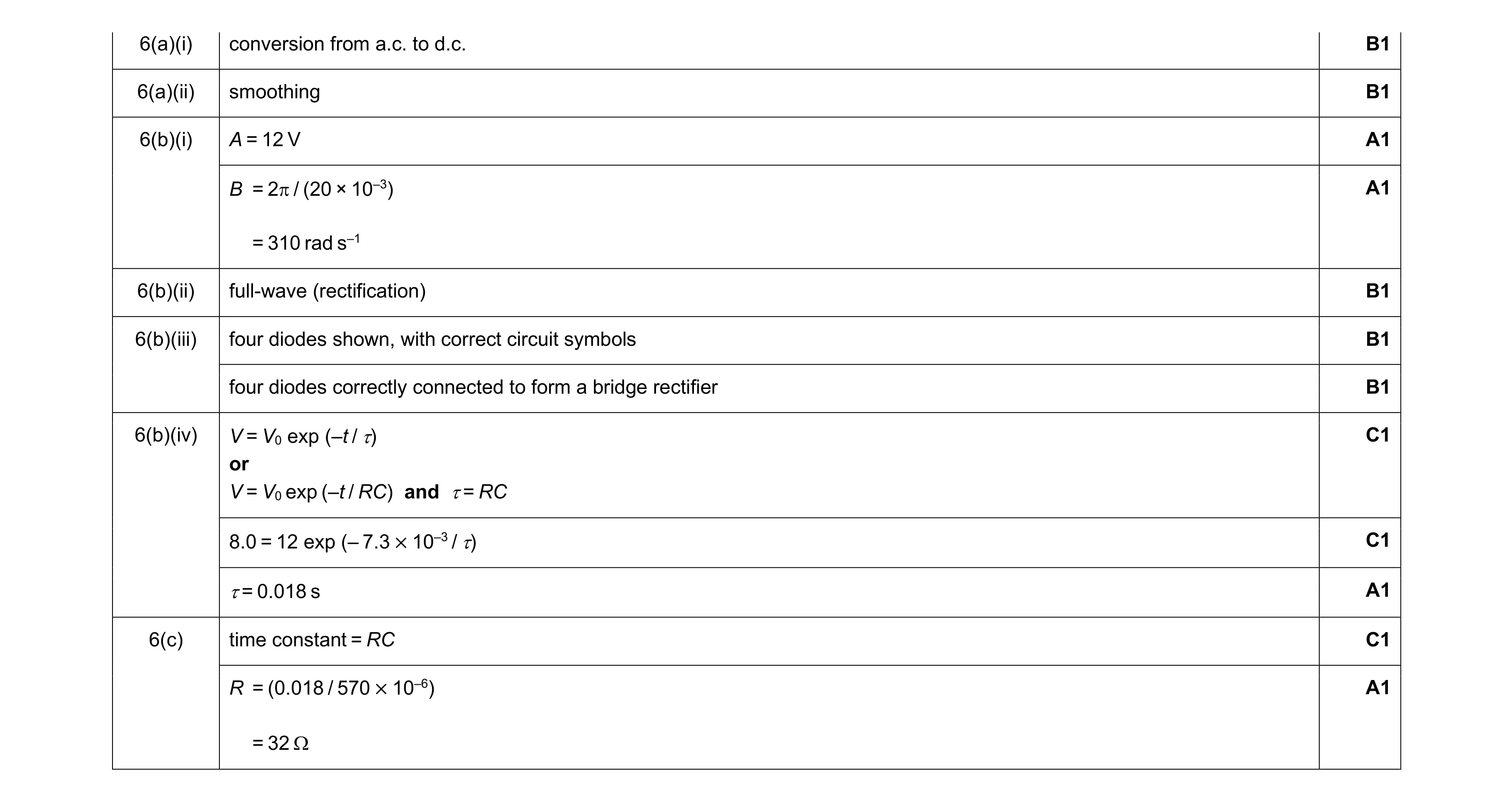 12
12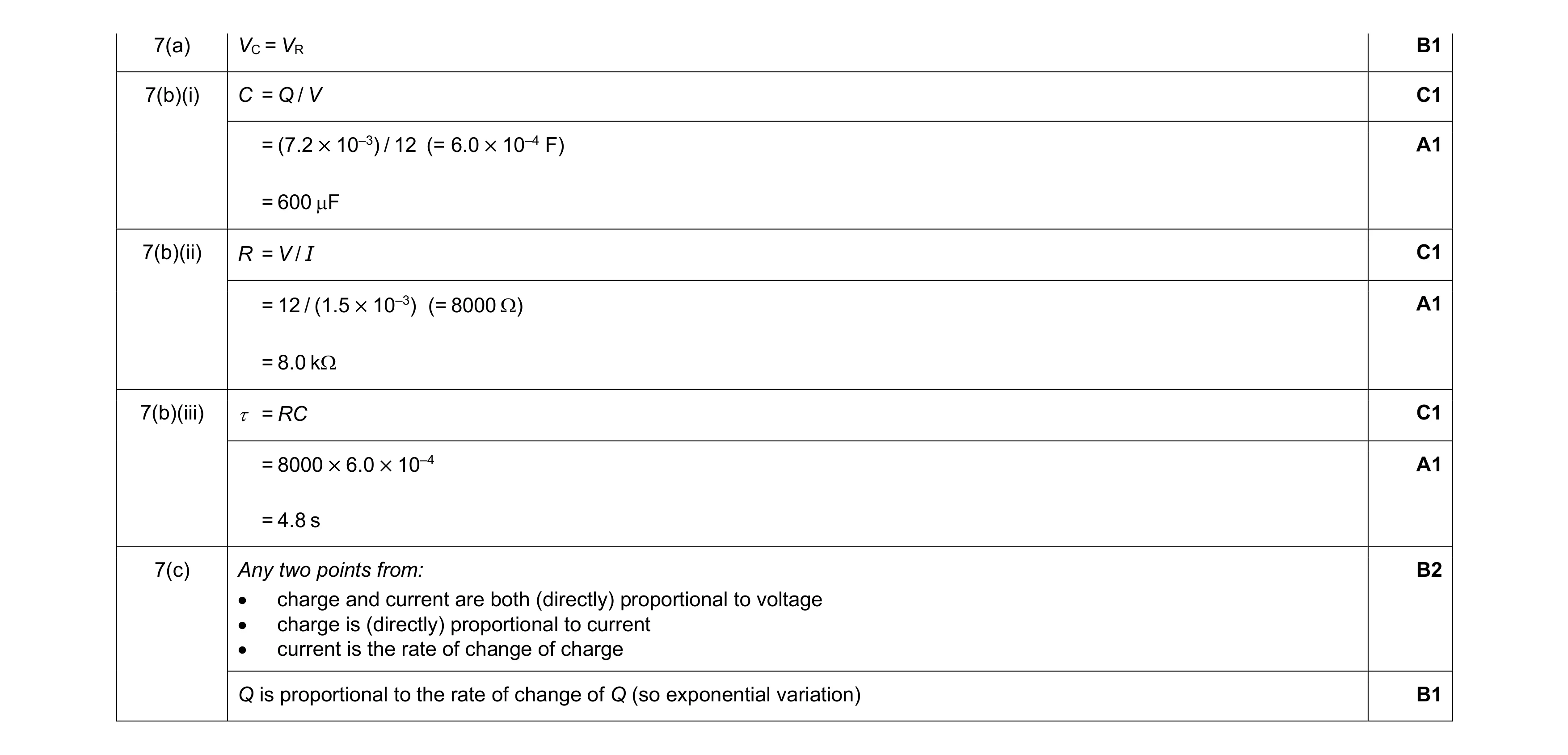 10
10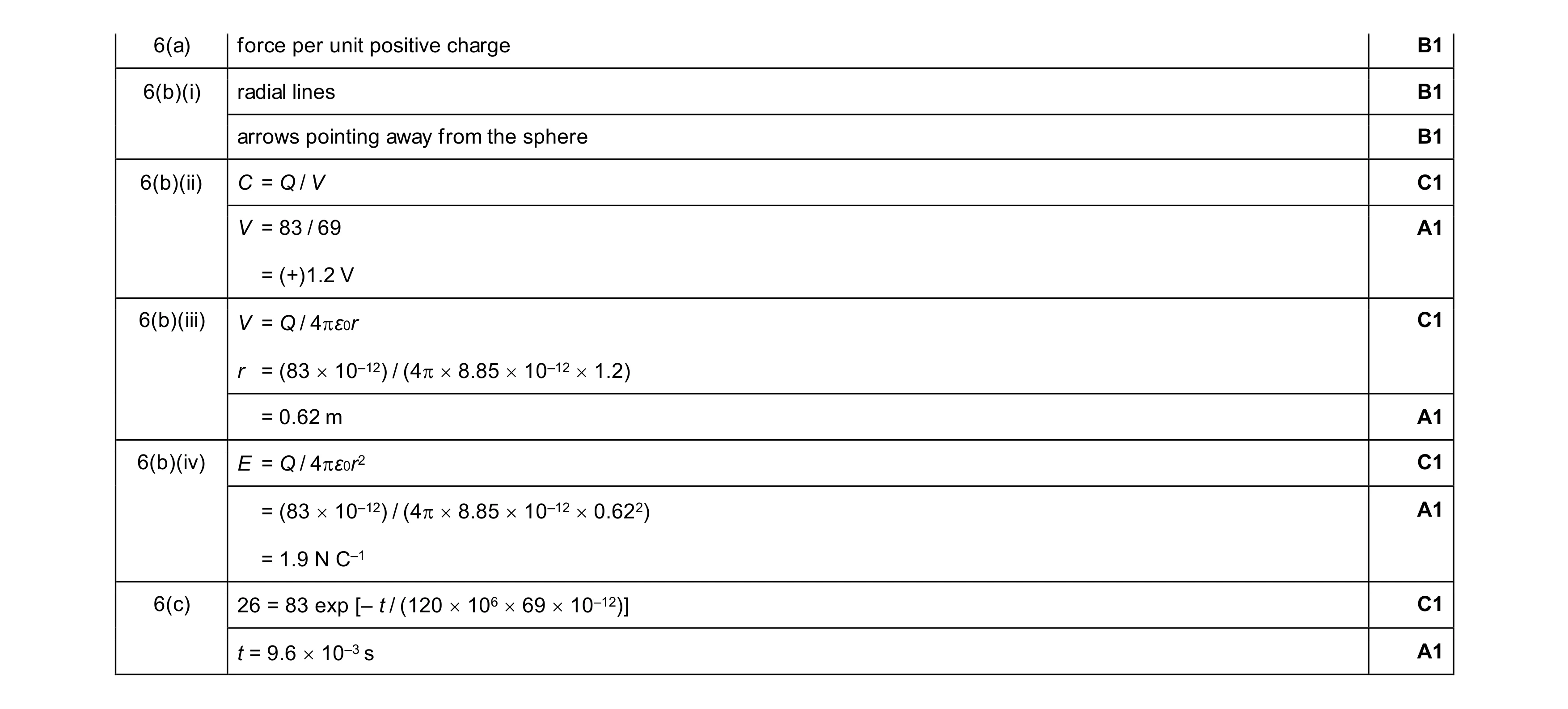 11
11