Questions as text
Q1 · A capacitor consists of two parallel metal plates, separated by an insulator, as shown in… 9702/42 May/June 2017
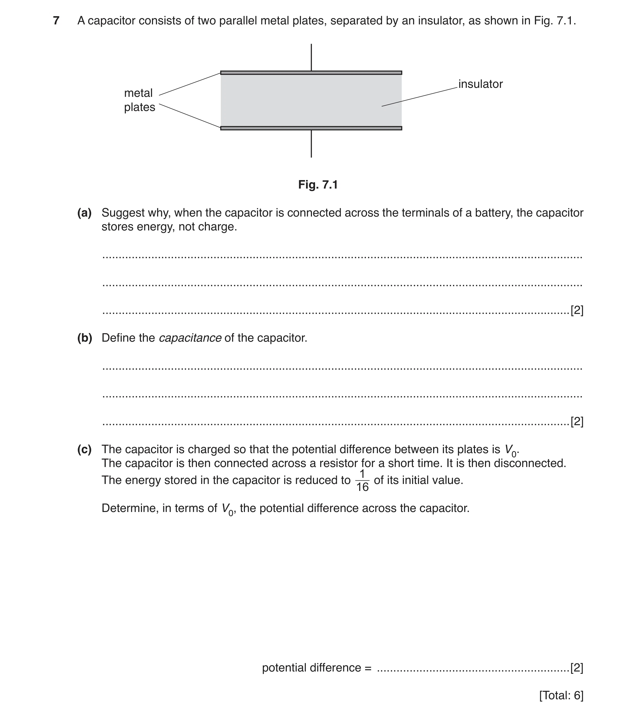
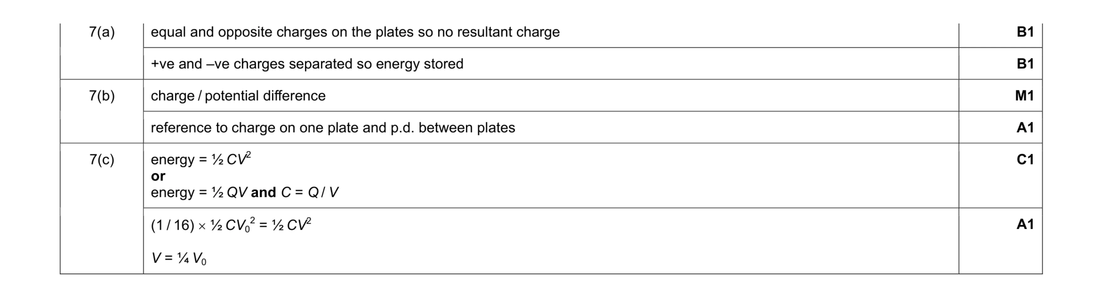
7 A capacitor consists of two parallel metal plates, separated by an insulator, as shown in Fig. 7.1. insulator metal plates Fig. 7.1 (a) Suggest why, when the capacitor is connected across the terminals of a battery, the capacitor stores energy, not charge. … … … [2] (b) Define the capacitance of the capacitor. … … … [2] (c) The capacitor is charged so that the potential difference between its plates is V0. The capacitor is then connected across a resistor for a short time. It is then disconnected. 1 The energy stored in the capacitor is reduced to of its initial value. 16 Determine, in terms of V0, the potential difference across the capacitor. potential difference = … [2] [Total: 6]
6 marks
Mark scheme: 7(a) equal and opposite charges on the plates so no resultant charge B1 +ve and –ve charges separated so energy stored B1 7(b) charge / potential difference M1 reference to charge on one plate and p.d. between plates A1 7(c) energy = ½ CV2 or energy = ½ QV and C = Q / V C1 (1 / 16) × ½ CV0 2 = ½ CV2 V = ¼ V0 A1
This question in 9702/42 May/June 2017
Q2 · Define the capacitance of a parallel-plate capacitor 9702/42 Feb/March 2019
6 (a) Define the capacitance of a parallel-plate capacitor. … … … [2] (b) A student has three capacitors. Two of the capacitors have a capacitance of 4.0 μF and one has a capacitance of 8.0 μF. Draw labelled circuit diagrams, one in each case, to show how the three capacitors may be connected to give a total capacitance of: (i) 1.6 μF [1] (ii) 10 μF. [1] (c) A capacitor C of capacitance 47 μF is connected across the output terminals of a bridge rectifier, as shown in Fig. 6.1. C bridge R rectifier 47 μF Fig. 6.1 The variation with time t of the potential difference V across the resistor R is shown in Fig. 6.2. 10 8 V / V 6 4 2 0 0 t1 t2 time t Fig. 6.2 Use data from Fig. 6.2 to determine the energy transfer from the capacitor C to the resistor R between time t1 and time t2. energy = … J [3] [Total: 7]
7 marks
Mark scheme: 6(a) charge / potential (difference) M1 charge on one plate, p.d. between the plates A1 6(b)(i) all three capacitors connected in series B1 6(b)(ii) 8 ( µF) in parallel with the two 4 (µF) capacitors connected in series B1 6(c) discharge from 7.0 V to 4.0 V C1 Either energy = ½CV2 or energy = ½ QV and C = Q / V C1 energy = ½ × 47 × 10–6 × (72 – 42) = 7.8 × 10⁻⁴ J A1
This question in 9702/42 Feb/March 2019
Q3 · A capacitor consists of two parallel metal plates, separated by air, at a variable… 9702/41 Oct/Nov 2021
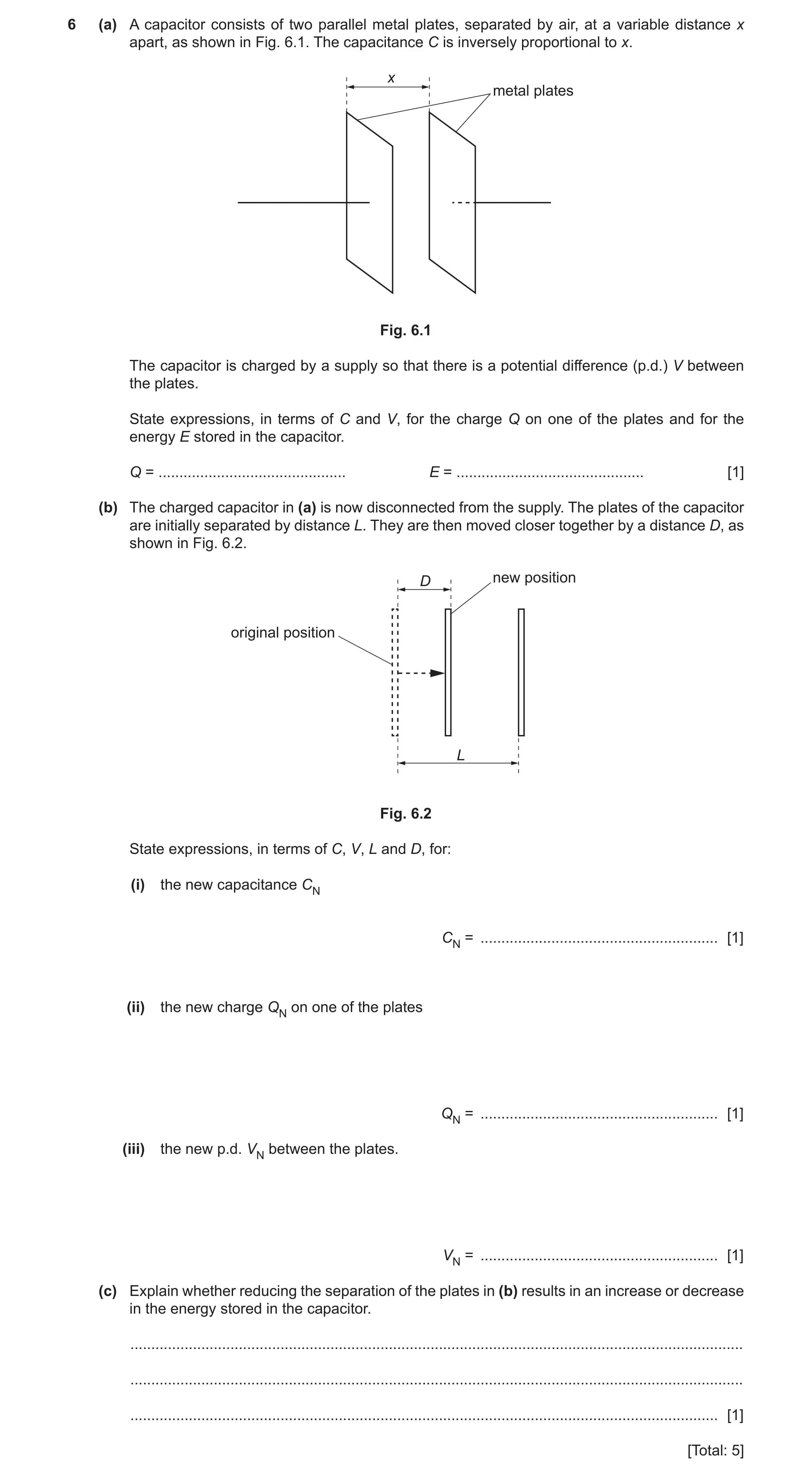
6 (a) A capacitor consists of two parallel metal plates, separated by air, at a variable distance x apart, as shown in Fig. 6.1. The capacitance C is inversely proportional to x. x metal plates Fig. 6.1 The capacitor is charged by a supply so that there is a potential difference (p.d.) V between the plates. State expressions, in terms of C and V, for the charge Q on one of the plates and for the energy E stored in the capacitor. Q = … E = … [1] (b) The charged capacitor in (a) is now disconnected from the supply. The plates of the capacitor are initially separated by distance L. They are then moved closer together by a distance D, as shown in Fig. 6.2. D new position original position L Fig. 6.2 State expressions, in terms of C, V, L and D, for: (i) the new capacitance CN CN = … [1] (ii) the new charge QN on one of the plates QN = … [1] (iii) the new p.d. VN between the plates. VN = … [1] (c) Explain whether reducing the separation of the plates in (b) results in an increase or decrease in the energy stored in the capacitor. … … … [1] [Total: 5]
5 marks
Mark scheme: 6(a) Q = CV and E = ½CV2 B1 6(b)(i) CN = CL / (L – D) B1 6(b)(ii) (charge is unchanged by moving the plates so) QN = CV B1 6(b)(iii) VN = QN / CN = (CV) / [CL / (L – D)] = V(L – D) / L B1 6(c) oppositely charged plates attract, so energy stored decreases B1
This question in 9702/41 Oct/Nov 2021
Q4 · A capacitor consists of two parallel metal plates, separated by air, at a variable… 9702/43 Oct/Nov 2021
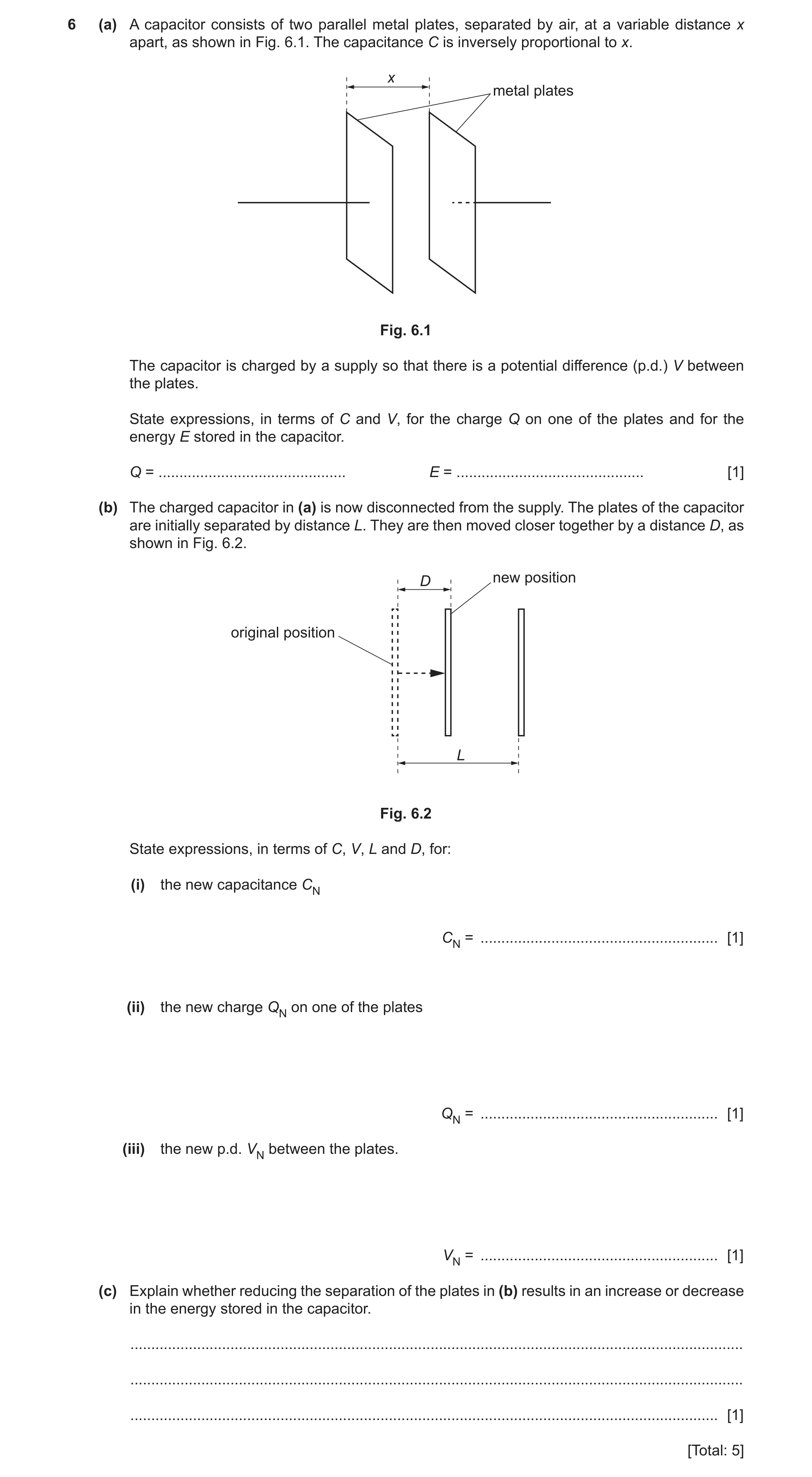
6 (a) A capacitor consists of two parallel metal plates, separated by air, at a variable distance x apart, as shown in Fig. 6.1. The capacitance C is inversely proportional to x. x metal plates Fig. 6.1 The capacitor is charged by a supply so that there is a potential difference (p.d.) V between the plates. State expressions, in terms of C and V, for the charge Q on one of the plates and for the energy E stored in the capacitor. Q = … E = … [1] (b) The charged capacitor in (a) is now disconnected from the supply. The plates of the capacitor are initially separated by distance L. They are then moved closer together by a distance D, as shown in Fig. 6.2. D new position original position L Fig. 6.2 State expressions, in terms of C, V, L and D, for: (i) the new capacitance CN CN = … [1] (ii) the new charge QN on one of the plates QN = … [1] (iii) the new p.d. VN between the plates. VN = … [1] (c) Explain whether reducing the separation of the plates in (b) results in an increase or decrease in the energy stored in the capacitor. … … … [1] [Total: 5]
5 marks
Mark scheme: 6(a) Q = CV and E = ½CV2 B1 6(b)(i) CN = CL / (L – D) B1 6(b)(ii) (charge is unchanged by moving the plates so) QN = CV B1 6(b)(iii) VN = QN / CN = (CV) / [CL / (L – D)] = V(L – D) / L B1 6(c) oppositely charged plates attract, so energy stored decreases B1
This question in 9702/43 Oct/Nov 2021
Q5 · The variation with potential difference V of the charge Q on one of the plates of a… 9702/42 Feb/March 2022
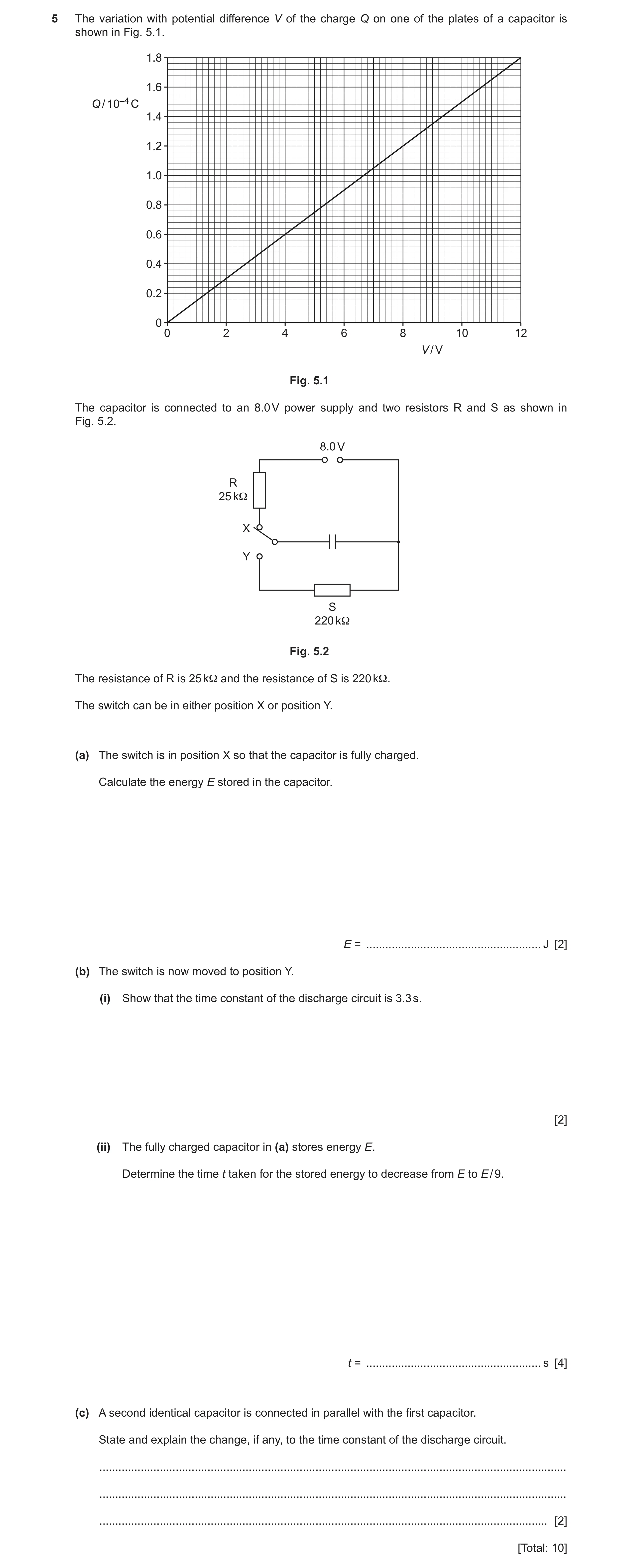
5 The variation with potential difference V of the charge Q on one of the plates of a capacitor is shown in Fig. 5.1. 1.8 1.6 Q / 10–4 C 1.4 1.2 1.0 0.8 0.6 0.4 0.2 0 0 2 4 6 8 10 12 V / V Fig. 5.1 The capacitor is connected to an 8.0 V power supply and two resistors R and S as shown in Fig. 5.2. 8.0 V R 25 kΩ X Y S 220 kΩ Fig. 5.2 The resistance of R is 25 kΩ and the resistance of S is 220 kΩ. The switch can be in either position X or position Y. (a) The switch is in position X so that the capacitor is fully charged. Calculate the energy E stored in the capacitor. E = … J [2] (b) The switch is now moved to position Y. (i) Show that the time constant of the discharge circuit is 3.3 s. [2] (ii) The fully charged capacitor in (a) stores energy E. Determine the time t taken for the stored energy to decrease from E to E / 9. t = … s [4] (c) A second identical capacitor is connected in parallel with the first capacitor. State and explain the change, if any, to the time constant of the discharge circuit. … … … [2] [Total: 10]
10 marks
Mark scheme: 5(a) (energy stored =) area under line or ½ QV = ½ × 8.0 × 1.2 × 10-4 = 4.8 × 10⁻⁴ J A1 5(b)(i) (τ=) RC C1 (τ=) 220 × 103 × (1.2 × 10-4/8.0) = 3.3 s A1 5(b)(ii) E ∝ V2 C1 (so time to) Vo / 3 tRC o V = V e − C1 t o 3.3 o V = V e 3 − t3.3 1 = e 3 − C1 t = 3.6 s A1 5(c) (total) capacitance is doubled M1 time constant is doubled A1
This question in 9702/42 Feb/March 2022
Q6 · A capacitor, a battery of electromotive force (e.m.f.) 12 V, a resistor R and a two-way… 9702/42 Feb/March 2023
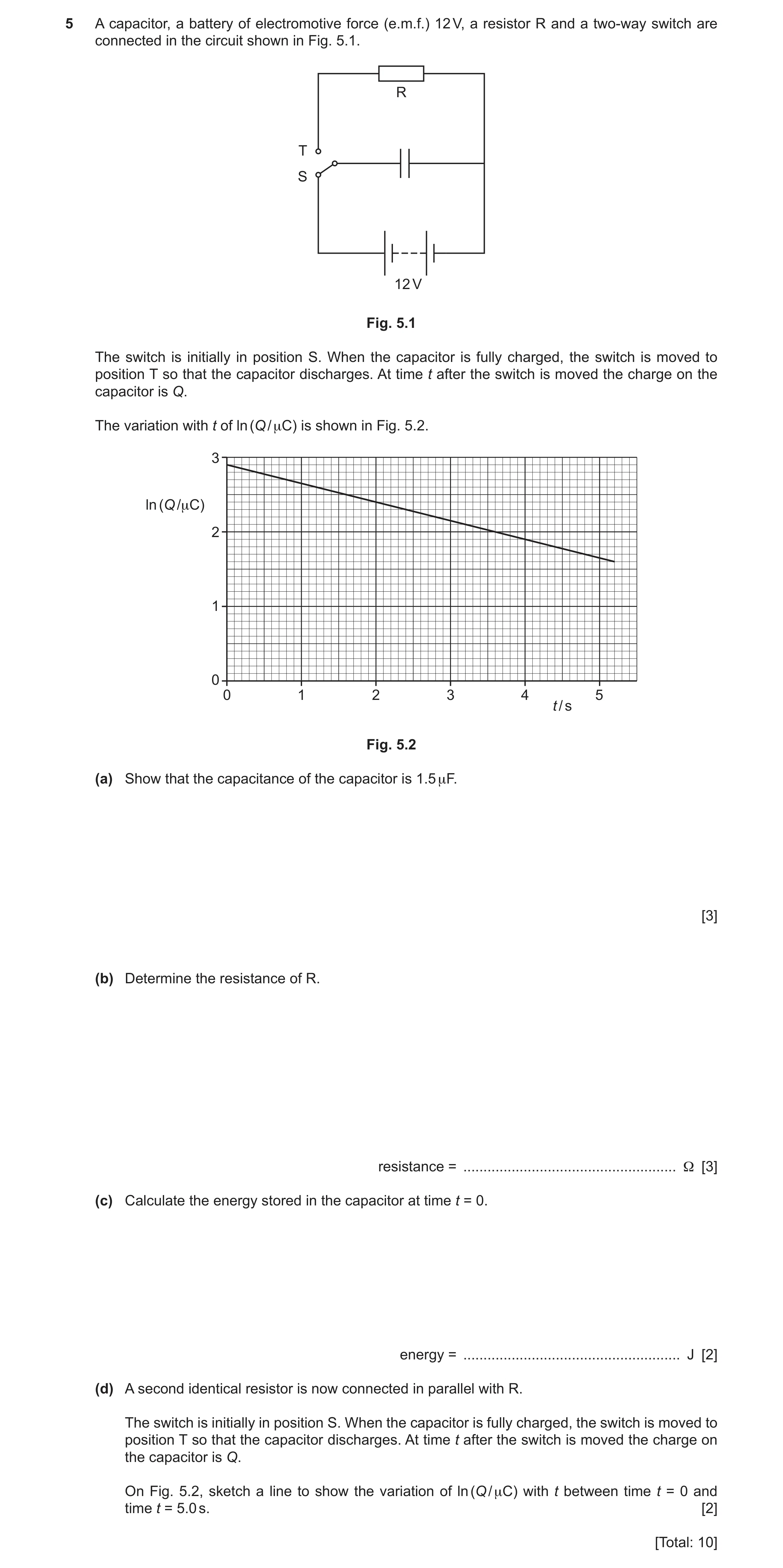
5 A capacitor, a battery of electromotive force (e.m.f.) 12 V, a resistor R and a two-way switch are connected in the circuit shown in Fig. 5.1. R T S 12 V Fig. 5.1 The switch is initially in position S. When the capacitor is fully charged, the switch is moved to position T so that the capacitor discharges. At time t after the switch is moved the charge on the capacitor is Q. The variation with t of ln (Q / μC) is shown in Fig. 5.2. 3 ln (Q /μC) 2 1 0 0 1 2 3 4 5 t / s Fig. 5.2 (a) Show that the capacitance of the capacitor is 1.5 μF. [3] (b) Determine the resistance of R. resistance = … Ω [3] (c) Calculate the energy stored in the capacitor at time t = 0. energy = … J [2] (d) A second identical resistor is now connected in parallel with R. The switch is initially in position S. When the capacitor is fully charged, the switch is moved to position T so that the capacitor discharges. At time t after the switch is moved the charge on the capacitor is Q. On Fig. 5.2, sketch a line to show the variation of ln (Q / μC) with t between time t = 0 and time t = 5.0 s. [2] [Total: 10]
10 marks
Mark scheme: 5(a) from graph ln Q = 2.9 B1 (so Q = 18.2 C) C = Q / V C1 = 18.2 / 12 = 1.5 F A1 5(b) gradient = –0.25 C1 gradient = –1 / RC C1 R = 1 / (0.25 1.5 10–6) A1 = 2.7 106 Q − tCR − t (C1) or = e or ln Q – ln Q0 = Q0 CR −5.2 −6 (C1) 4.95 (1.5 10 R ) e.g. = e or 1.6 – 2.9 = 5.2 / (1.5 × 10⁻⁶R) 18.2 R = 2.7 106 (A1) 5(c) W = ½ QV C1 = ½ 18.2 10–6 12 A1 = 1.1 10–4 J or W = ½ CV2 (C1) = ½ 1.5 10–6 122 (A1) = 1.1 10–4 J or W = ½ Q2 / C (C1) = ½ (18.2 10–6)2 / 1.5 10–6 (A1) = 1.1 10–4 J 5(d) straight line with different negative gradient starting from (0, 2.9) M1 straight line between t = 0 and at least t = 5.0 s with twice the gradient of the original line A1
This question in 9702/42 Feb/March 2023
Q7 · Two capacitors A and B are connected into the circuit shown in Fig 9702/42 May/June 2023
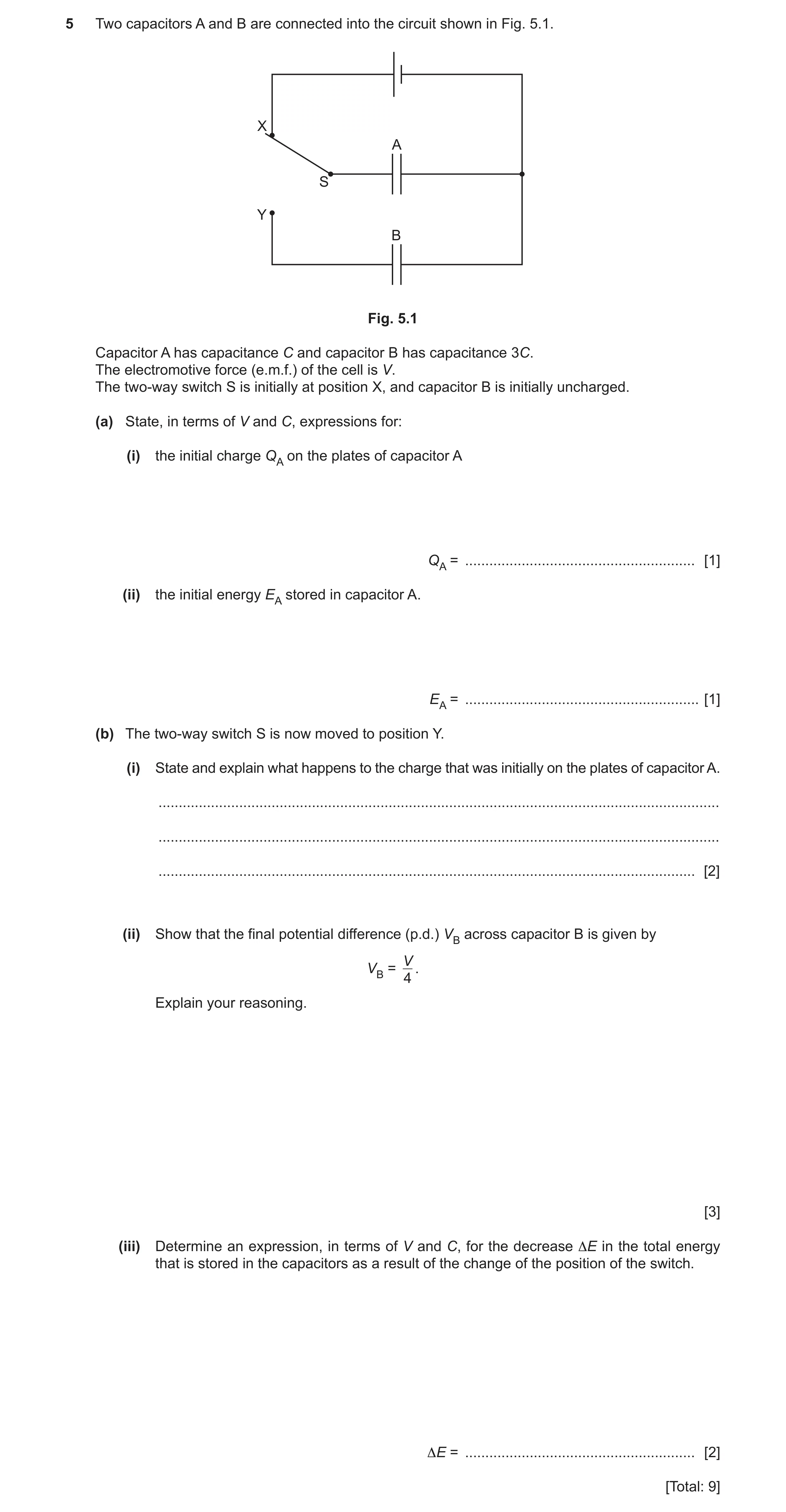
5 Two capacitors A and B are connected into the circuit shown in Fig. 5.1. X A S Y B Fig. 5.1 Capacitor A has capacitance C and capacitor B has capacitance 3C. The electromotive force (e.m.f.) of the cell is V. The two-way switch S is initially at position X, and capacitor B is initially uncharged. (a) State, in terms of V and C, expressions for: (i) the initial charge QA on the plates of capacitor A QA = … [1] (ii) the initial energy EA stored in capacitor A. EA = … [1] (b) The two-way switch S is now moved to position Y. (i) State and explain what happens to the charge that was initially on the plates of capacitor A. … … … [2] (ii) Show that the final potential difference (p.d.) VB across capacitor B is given by V VB = . 4 Explain your reasoning. [3] (iii) Determine an expression, in terms of V and C, for the decrease ΔE in the total energy that is stored in the capacitors as a result of the change of the position of the switch. ΔE = … [2] [Total: 9]
9 marks
Mark scheme: 5(a)(i) QA = CV A1 5(a)(ii) EA = ½CV2 A1 5(b)(i) some of the charge transfers to (the plates of) capacitor B B1 transfer is because the p.d.s across the capacitors are not equal or transfer stops when the p.d.s across the capacitors become equal B1 5(b)(ii) VA = VB M1 charge on A + charge on B = CV M1 CVB + 3CVB = CV leading to VB = V / 4 A1 or CT = 4C (M1) QT = CV (M1) VB = CV / 4C = V / 4 (A1) 5(b)(iii) E = ½CV2 – nCV2, where n is a multiple that is less than ½ or total final energy = ½ 4C (V / 4)2 = ⅛CV2 C1 E = ½CV2 – ⅛CV2 = ⅜CV2 A1
This question in 9702/42 May/June 2023
Q8 · A capacitor C is charged so that the potential difference (p.d.) V across its terminals… 9702/42 Oct/Nov 2023
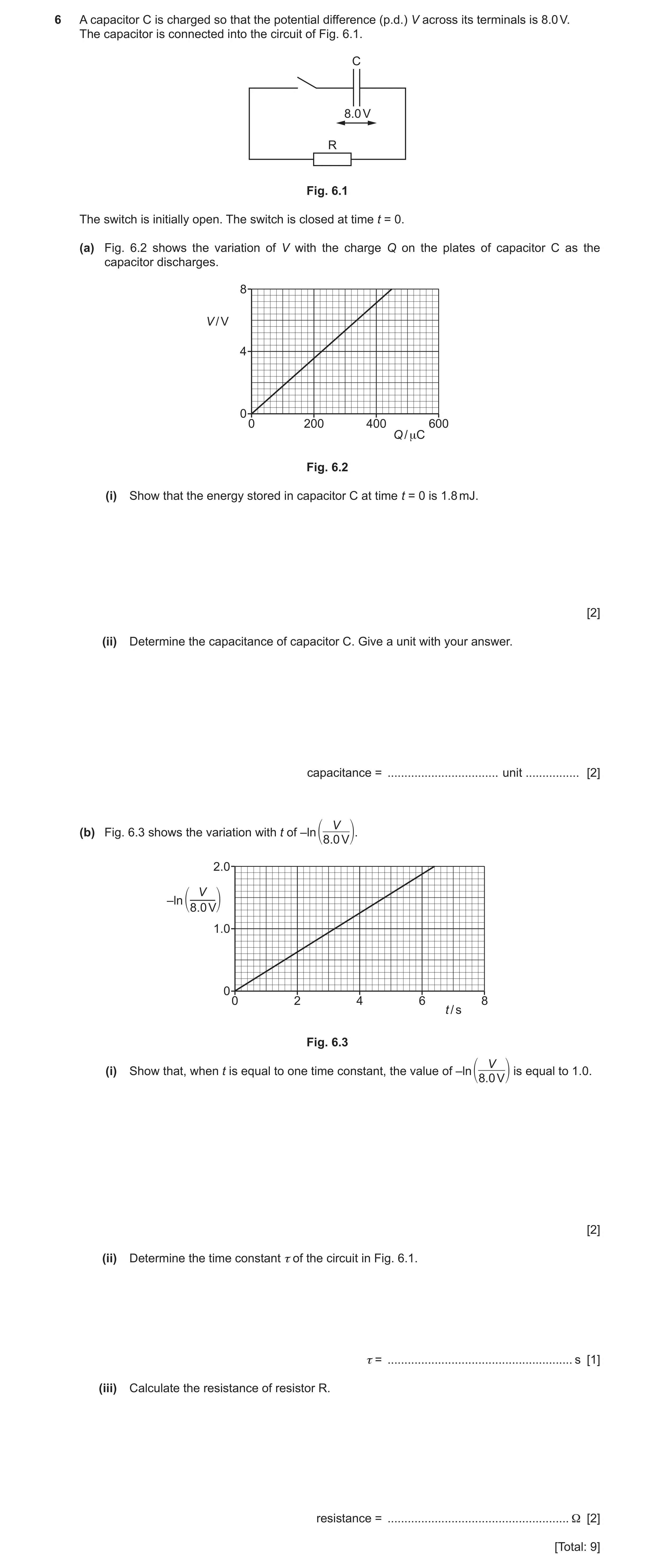
6 A capacitor C is charged so that the potential difference (p.d.) V across its terminals is 8.0 V. The capacitor is connected into the circuit of Fig. 6.1. C 8.0 V R Fig. 6.1 The switch is initially open. The switch is closed at time t = 0. (a) Fig. 6.2 shows the variation of V with the charge Q on the plates of capacitor C as the capacitor discharges. 8 V / V 4 0 0 200 400 600 Q / μC Fig. 6.2 (i) Show that the energy stored in capacitor C at time t = 0 is 1.8 mJ. [2] (ii) Determine the capacitance of capacitor C. Give a unit with your answer. capacitance = … unit … [2] V(b) Fig. 6.3 shows the variation with t of –ln 8.0 V. 2.0 V –ln 1 8.0 V2 1.0 0 0 2 4 6 8 t / s Fig. 6.3 V (i) Show that, when t is equal to one time constant, the value of –ln is equal to 1.0. 8.0 V [2] (ii) Determine the time constant τ of the circuit in Fig. 6.1. τ = … s [1] (iii) Calculate the resistance of resistor R. resistance = … Ω [2] [Total: 9]
9 marks
Mark scheme: 6(a)(i) energy stored = area under graph C1 = ½ 450 10–6 8.0 = 1.8 10–3 J or 1.8 mJ A1 6(a)(ii) C = Q / V or E = ½CV2 C1 C = (450 10–6) / 8.0 or (2 1.8 10–3) / 8.02 A1 = 5.6 10–5 F 6(b)(i) V = V0 exp (– t / RC) and = RC C1 V = V0 exp (– t / ) A1 V0 = 8.0 V, and at one time constant, t = V / 8.0 = exp (– / ), so ln (V / 8.0) = –1.0 or –ln (V / 8.0) = 1.0 6(b)(ii) [t read from graph at –ln (V / 8.0) = 1.0]: = 3.2 s A1 6(b)(iii) = RC C1 R = 3.2 / (5.6 10–5) A1 = 5.7 104
This question in 9702/42 Oct/Nov 2023
Q9 · Two capacitors X and Y are connected in series to a power supply of voltage V, as shown… 9702/42 May/June 2024
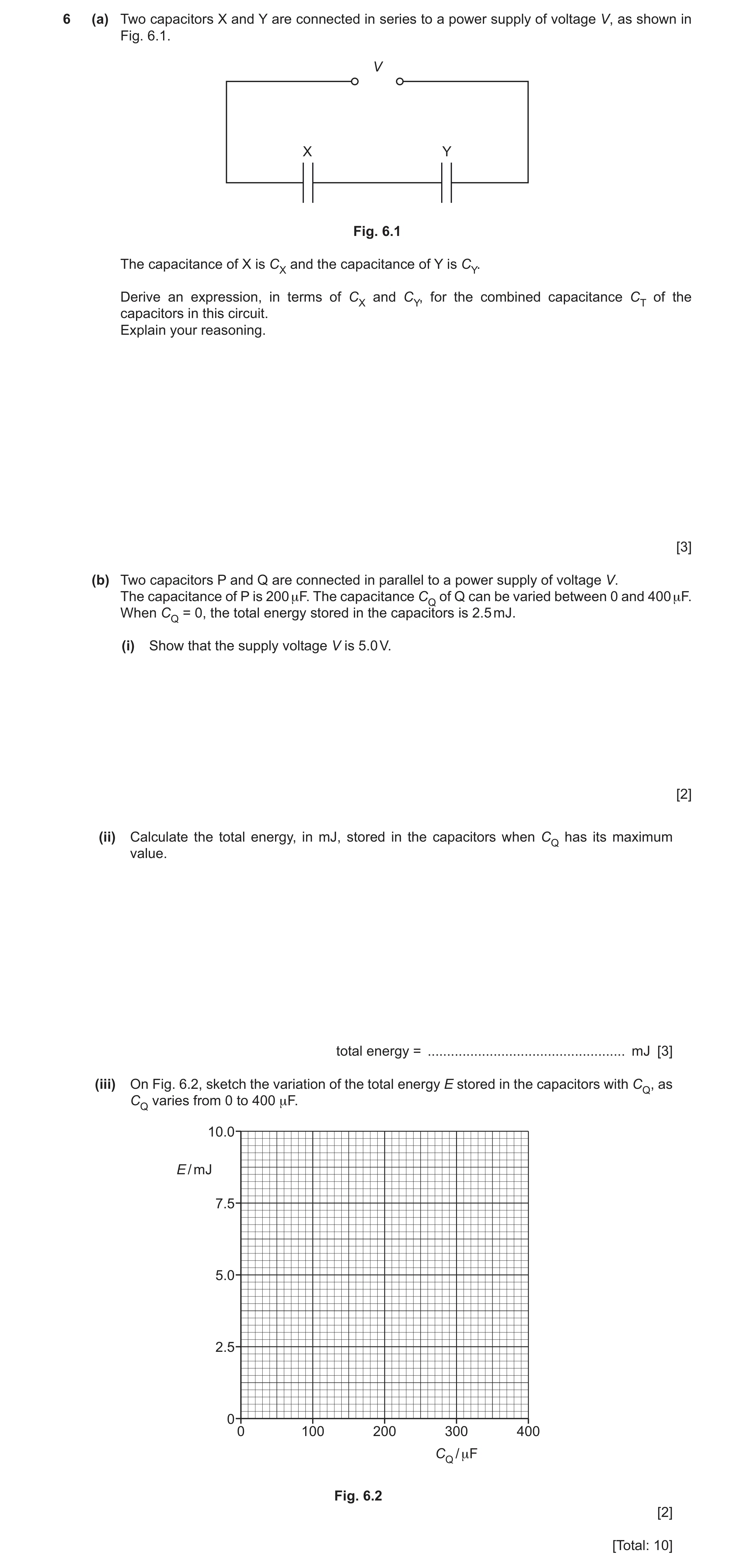
6 (a) Two capacitors X and Y are connected in series to a power supply of voltage V, as shown in Fig. 6.1. V X Y Fig. 6.1 The capacitance of X is CX and the capacitance of Y is CY. Derive an expression, in terms of CX and CY, for the combined capacitance CT of the capacitors in this circuit. Explain your reasoning. [3] (b) Two capacitors P and Q are connected in parallel to a power supply of voltage V. The capacitance of P is 200 μF. The capacitance CQ of Q can be varied between 0 and 400 μF. When CQ = 0, the total energy stored in the capacitors is 2.5 mJ. (i) Show that the supply voltage V is 5.0 V. [2] (ii) Calculate the total energy, in mJ, stored in the capacitors when CQ has its maximum value. total energy = … mJ [3] (iii) On Fig. 6.2, sketch the variation of the total energy E stored in the capacitors with CQ, as CQ varies from 0 to 400 μF. 10.0 E / mJ 7.5 5.0 2.5 0 0 100 200 300 400 CQ / μF Fig. 6.2 [2] [Total: 10]
10 marks
Mark scheme: 6(a) equal charge on both capacitors B1 VX + VY = V M1 (Q / CX) + (Q / CY) = (Q / CT) leading to (1 / CX) + (1 / CY) = (1 / CT) or (VX/ Q) + (VY/ Q) = (V / Q) leading to (1 / CX) + (1 / CY) = (1 / CT) A1 6(b)(i) E = ½CV 2 C1 V = √[(2 2.5 10–3) / (200 10–6)] = 5.0 V A1 6(b)(ii) total capacitance = 600 F C1 E = ½ 600 10–6 5.02 ( = 7.5 10–3 J) C1 = 7.5 mJ A1 6(b)(iii) line with positive gradient starting at (0, 2.5) B1 straight line passing through (400, 7.5) B1
This question in 9702/42 May/June 2024
Q10 · Define the capacitance of a parallel‑plate capacitor 9702/42 Oct/Nov 2024
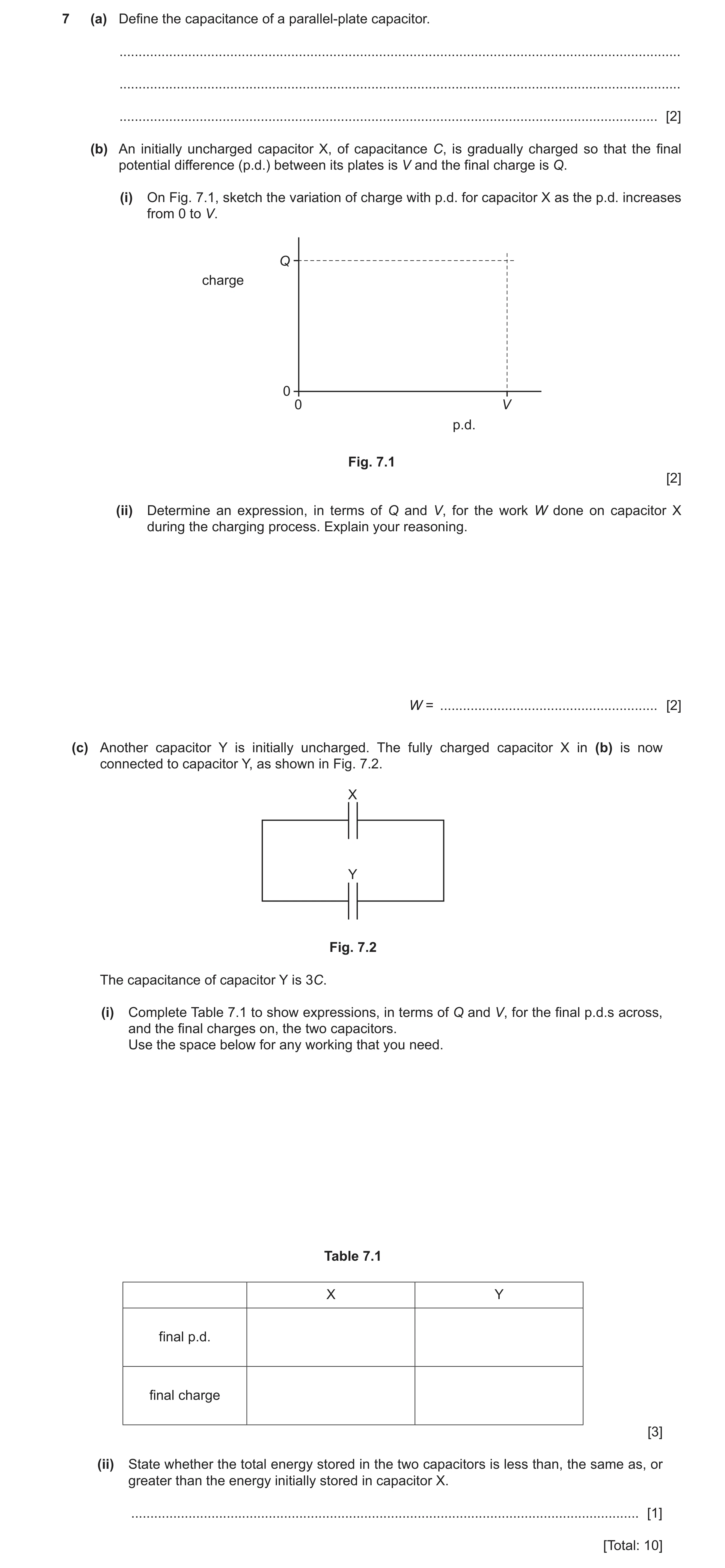
7 (a) Define the capacitance of a parallel‑plate capacitor. … … … [2] (b) An initially uncharged capacitor X, of capacitance C, is gradually charged so that the final potential difference (p.d.) between its plates is V and the final charge is Q. (i) On Fig. 7.1, sketch the variation of charge with p.d. for capacitor X as the p.d. increases from 0 to V. Q charge 0 0 V p.d. Fig. 7.1 [2] (ii) Determine an expression, in terms of Q and V, for the work W done on capacitor X during the charging process. Explain your reasoning. W = … [2] (c) Another capacitor Y is initially uncharged. The fully charged capacitor X in (b) is now connected to capacitor Y, as shown in Fig. 7.2. X Y Fig. 7.2 The capacitance of capacitor Y is 3C. (i) Complete Table 7.1 to show expressions, in terms of Q and V, for the final p.d.s across, and the final charges on, the two capacitors. Use the space below for any working that you need. Table 7.1 X Y final p.d. final charge [3] (ii) State whether the total energy stored in the two capacitors is less than, the same as, or greater than the energy initially stored in capacitor X. … [1] [Total: 10]
10 marks
Mark scheme: 7(a) charge / potential (difference) M1 charge is charge on one plate, and potential is p.d. between the plates A1 7(b)(i) straight line starting at the origin B1 line with positive gradient ending at (V, Q) B1 7(b)(ii) work done is the area under the graph B1 W = ½QV A1 7(c)(i) final p.d. shown as V / 4 for both capacitors B1 final charges add together to give Q B1 charge on Y = 3 charge on X (and both charges shown as a multiple of Q) B1 Fully correct answer: X Y final p.d. V / 4 V / 4 final charge Q / 4 3Q / 4 7(c)(ii) less than B1
This question in 9702/42 Oct/Nov 2024
Q11 · Two parallel plate capacitors C1 and C2 are connected to a supply that has a potential… 9702/41 Oct/Nov 2025
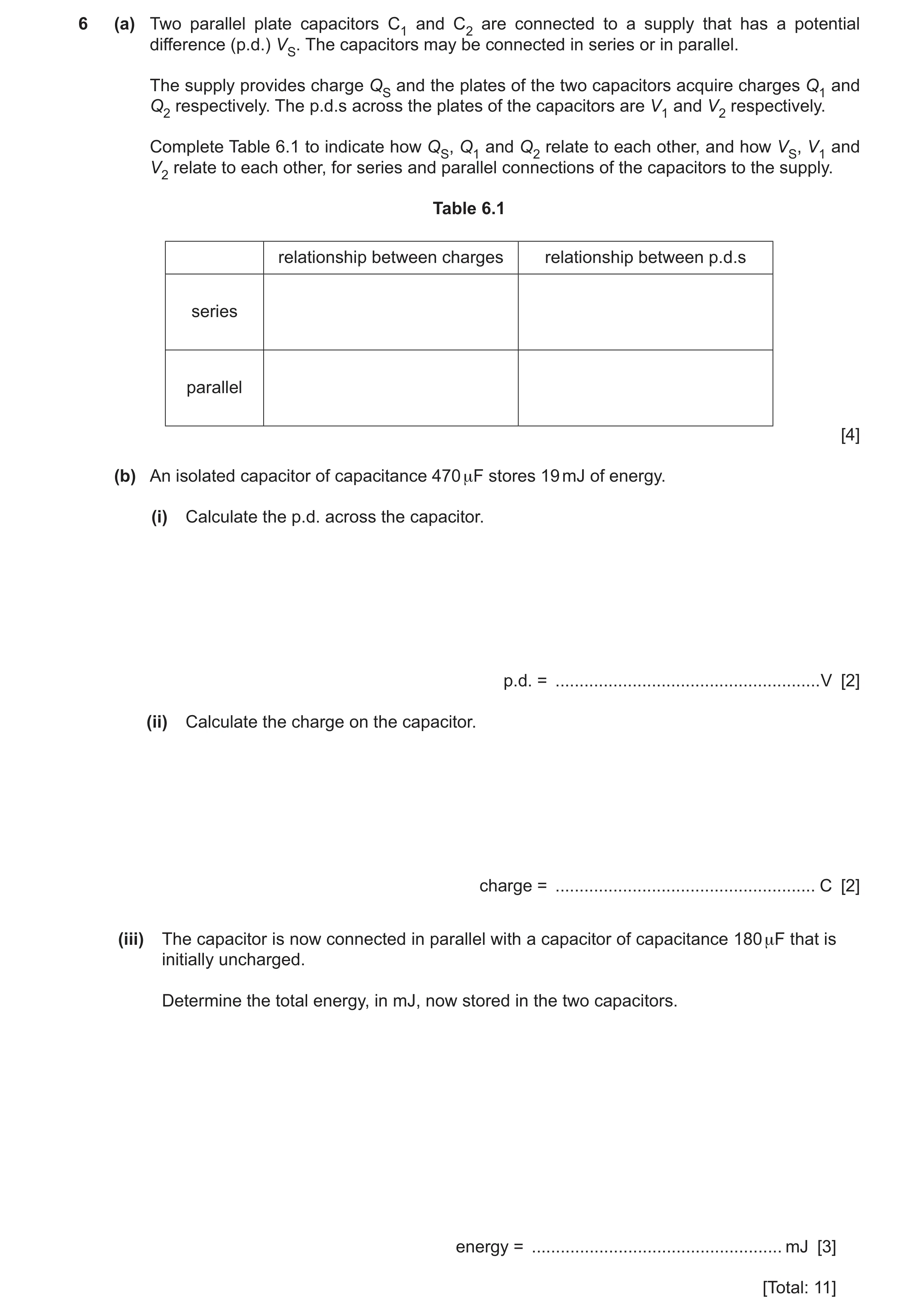
6 (a) Two parallel plate capacitors C1 and C2 are connected to a supply that has a potential difference (p.d.) VS. The capacitors may be connected in series or in parallel. The supply provides charge QS and the plates of the two capacitors acquire charges Q1 and Q2 respectively. The p.d.s across the plates of the capacitors are V1 and V2 respectively. Complete Table 6.1 to indicate how QS, Q1 and Q2 relate to each other, and how VS, V1 and V2 relate to each other, for series and parallel connections of the capacitors to the supply. Table 6.1 relationship between charges relationship between p.d.s series parallel [4] (b) An isolated capacitor of capacitance 470 μF stores 19 mJ of energy. (i) Calculate the p.d. across the capacitor. p.d. = … V [2] (ii) Calculate the charge on the capacitor. charge = … C [2] (iii) The capacitor is now connected in parallel with a capacitor of capacitance 180 μF that is initially uncharged. Determine the total energy, in mJ, now stored in the two capacitors. energy = … mJ [3] [Total: 11]
11 marks
Mark scheme: 6(a) series charges: QS = Q1 = Q2 B1 series p.d.s: VS = V1 + V2 B1 parallel charges: QS = Q1 + Q2 B1 parallel p.d.s: VS = V1 = V2 B1 6(b)(i) E = ½ CV2 C1 p.d. = [(2 19 10–3) / (470 10–6)]½ A1 = 9.0 V 6(b)(ii) E = Q2 / 2C or C = Q / V C1 Q = (19 × 10–3 × 2 × 470 × 10–6)½ A1 or Q = 470 × 10–6 × 9.0 Q = 4.2 10–3 C 6(b)(iii) total charge unchanged C1 total capacitance = (470 + 180) 10–6 (F) C1 E = Q2 / 2C = (4.23 10–3)2 / (2 650 10–6) (= 0.014 J) A1 E = 14 mJ
This question in 9702/41 Oct/Nov 2025
Q12 · Two parallel plate capacitors C1 and C2 are connected to a supply that has a potential… 9702/43 Oct/Nov 2025
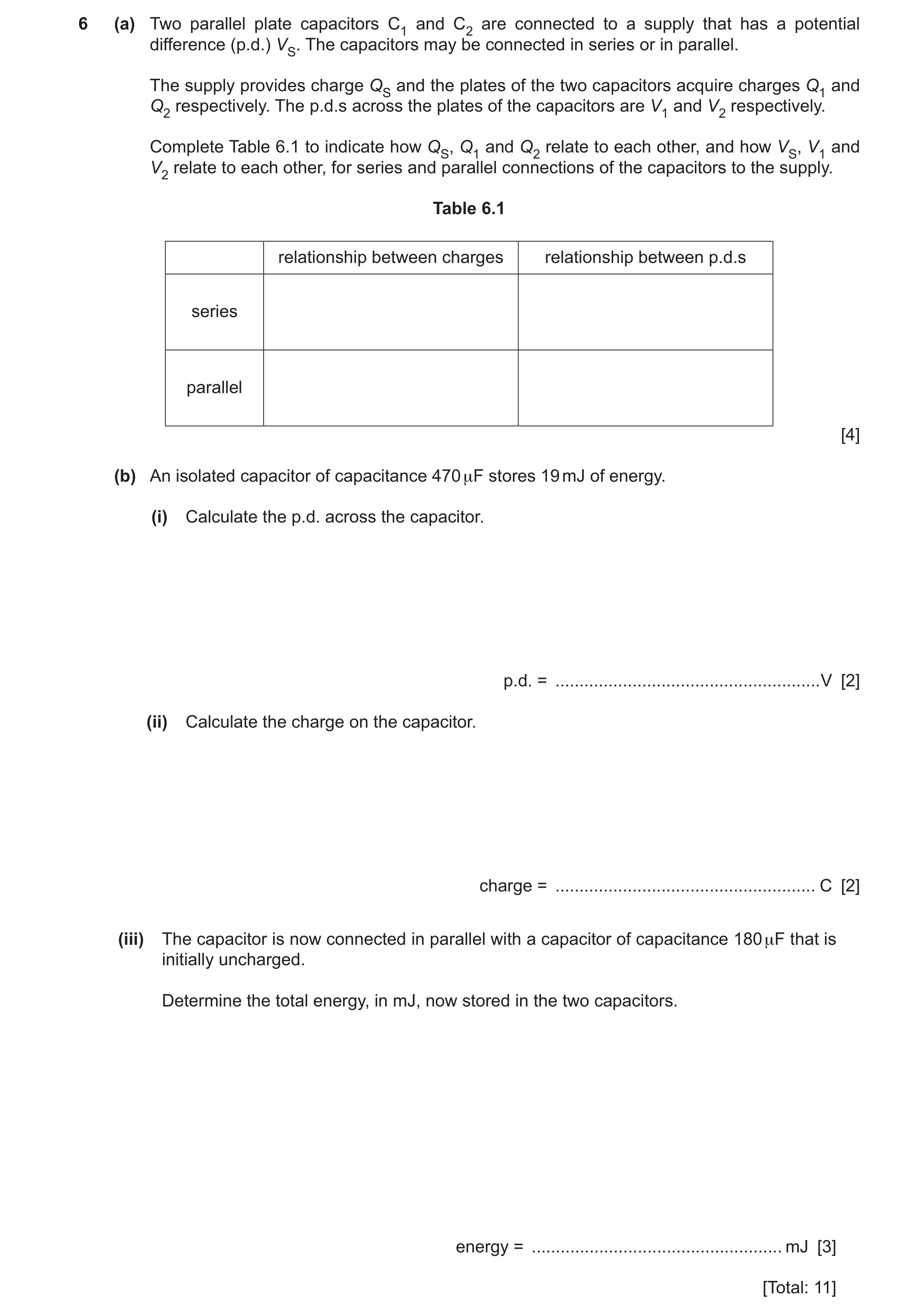
6 (a) Two parallel plate capacitors C1 and C2 are connected to a supply that has a potential difference (p.d.) VS. The capacitors may be connected in series or in parallel. The supply provides charge QS and the plates of the two capacitors acquire charges Q1 and Q2 respectively. The p.d.s across the plates of the capacitors are V1 and V2 respectively. Complete Table 6.1 to indicate how QS, Q1 and Q2 relate to each other, and how VS, V1 and V2 relate to each other, for series and parallel connections of the capacitors to the supply. Table 6.1 relationship between charges relationship between p.d.s series parallel [4] (b) An isolated capacitor of capacitance 470 μF stores 19 mJ of energy. (i) Calculate the p.d. across the capacitor. p.d. = … V [2] (ii) Calculate the charge on the capacitor. charge = … C [2] (iii) The capacitor is now connected in parallel with a capacitor of capacitance 180 μF that is initially uncharged. Determine the total energy, in mJ, now stored in the two capacitors. energy = … mJ [3] [Total: 11]
11 marks
Mark scheme: 6(a) series charges: QS = Q1 = Q2 B1 series p.d.s: VS = V1 + V2 B1 parallel charges: QS = Q1 + Q2 B1 parallel p.d.s: VS = V1 = V2 B1 6(b)(i) E = ½ CV2 C1 p.d. = [(2 19 10–3) / (470 10–6)]½ A1 = 9.0 V 6(b)(ii) E = Q2 / 2C or C = Q / V C1 Q = (19 × 10–3 × 2 × 470 × 10–6)½ A1 or Q = 470 × 10–6 × 9.0 Q = 4.2 10–3 C 6(b)(iii) total charge unchanged C1 total capacitance = (470 + 180) 10–6 (F) C1 E = Q2 / 2C = (4.23 10–3)2 / (2 650 10–6) (= 0.014 J) A1 E = 14 mJ
This question in 9702/43 Oct/Nov 2025
 1 / 18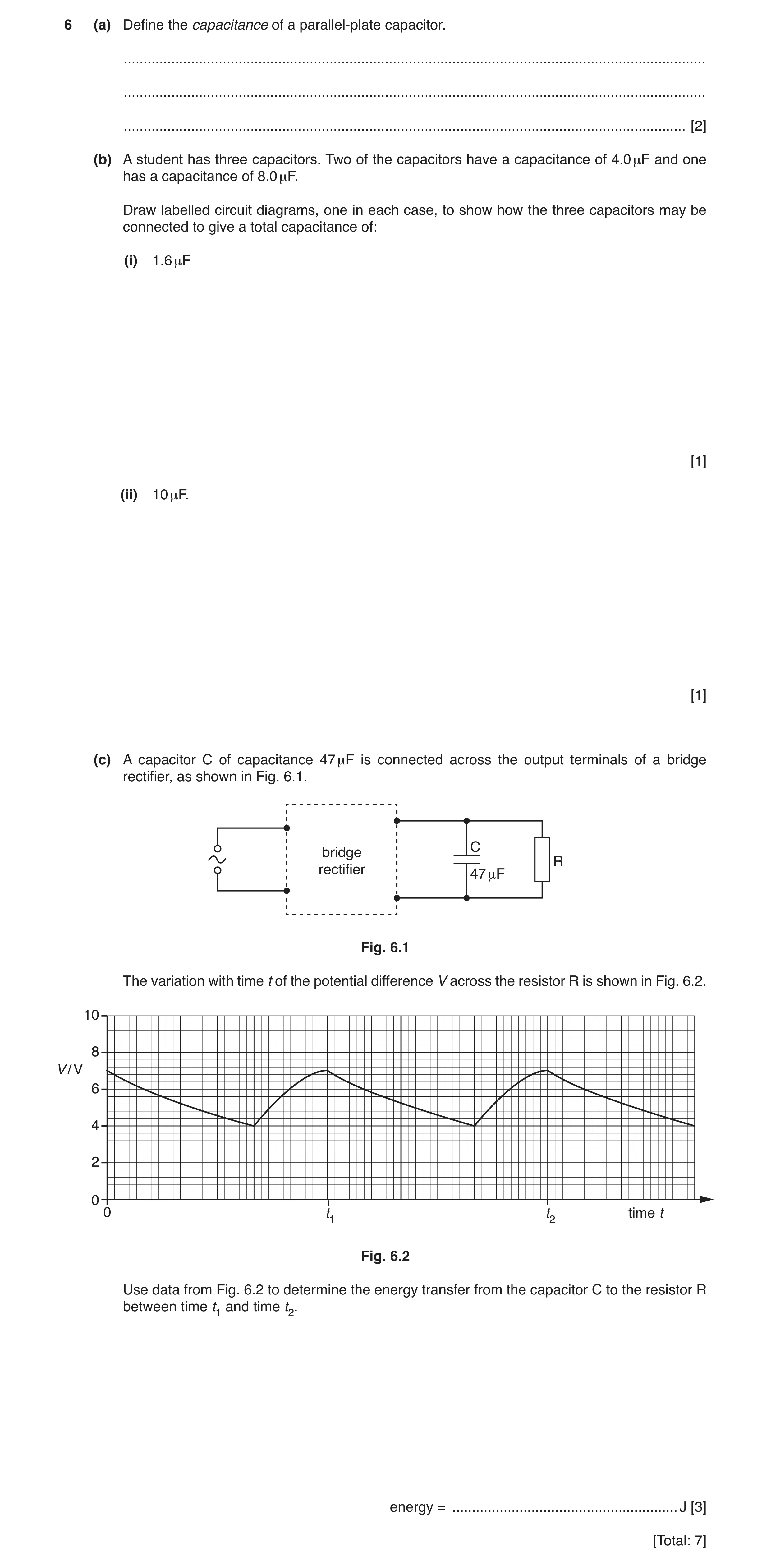
 17 / 18
 18 / 18
 6
6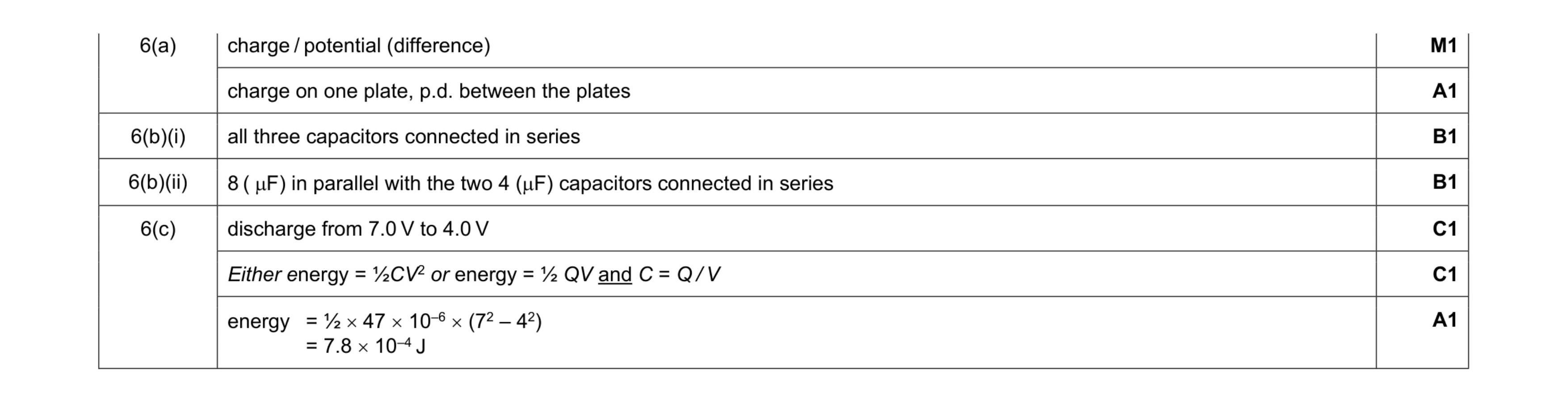 7
7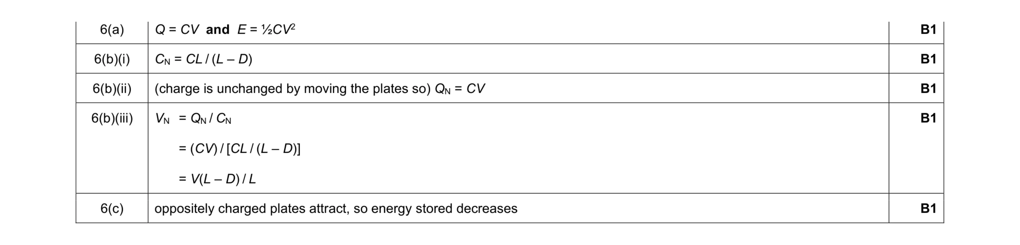 5
5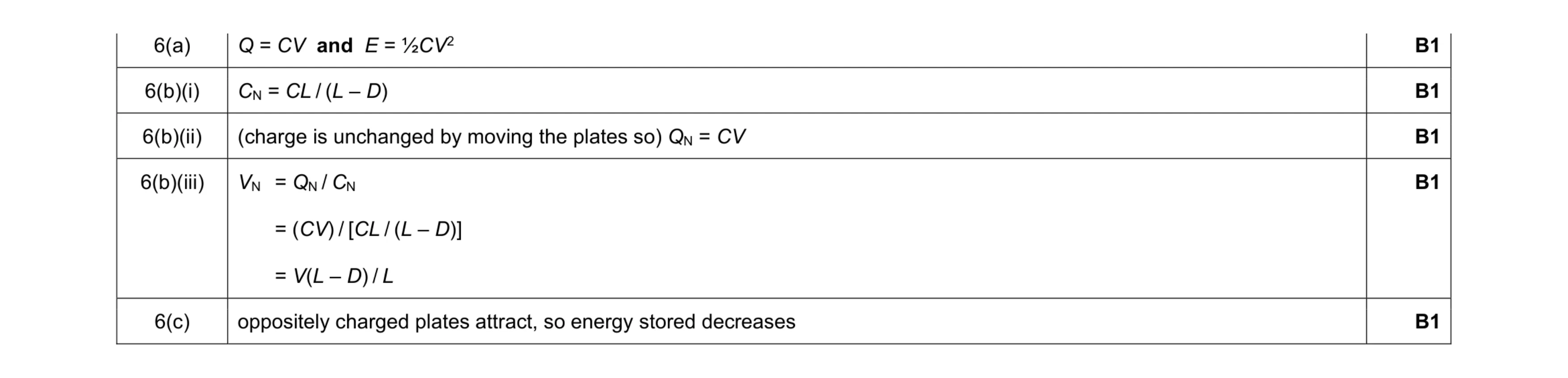 5
5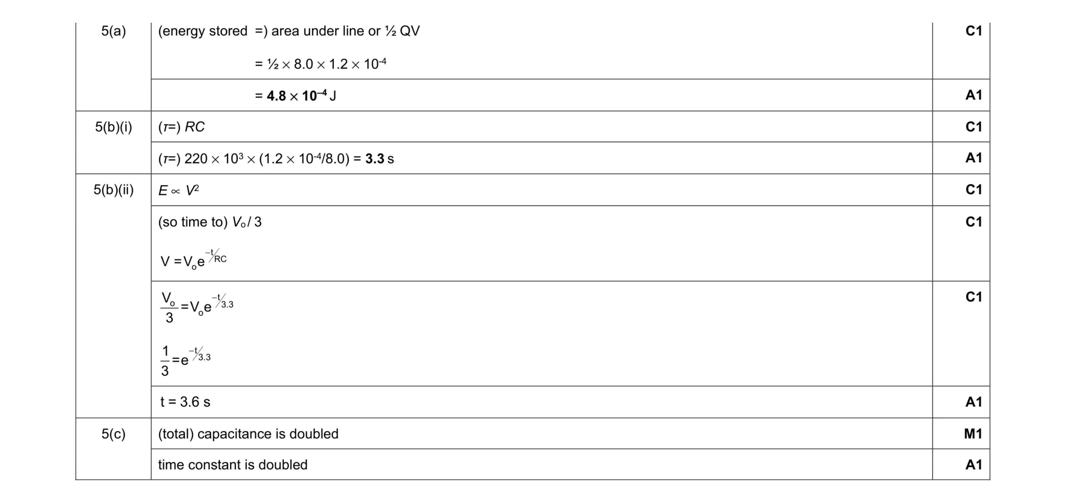 10
10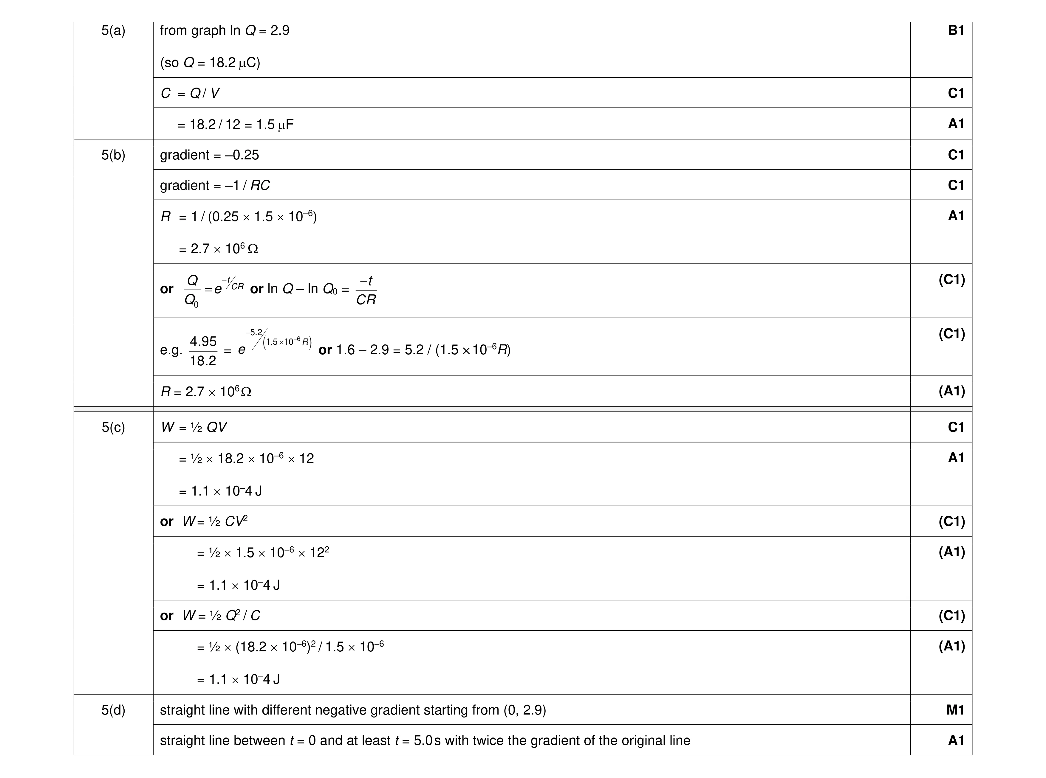 10
10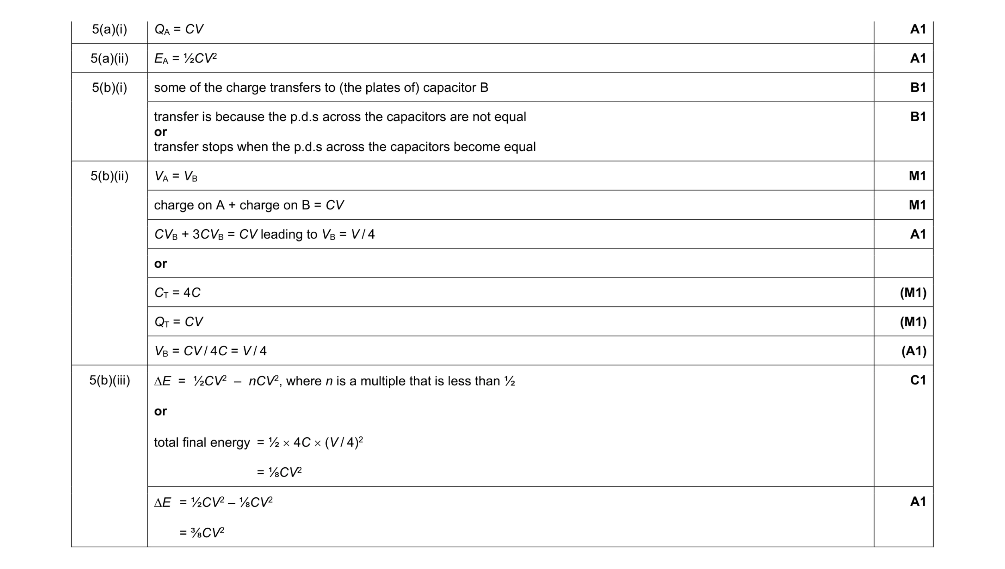 9
9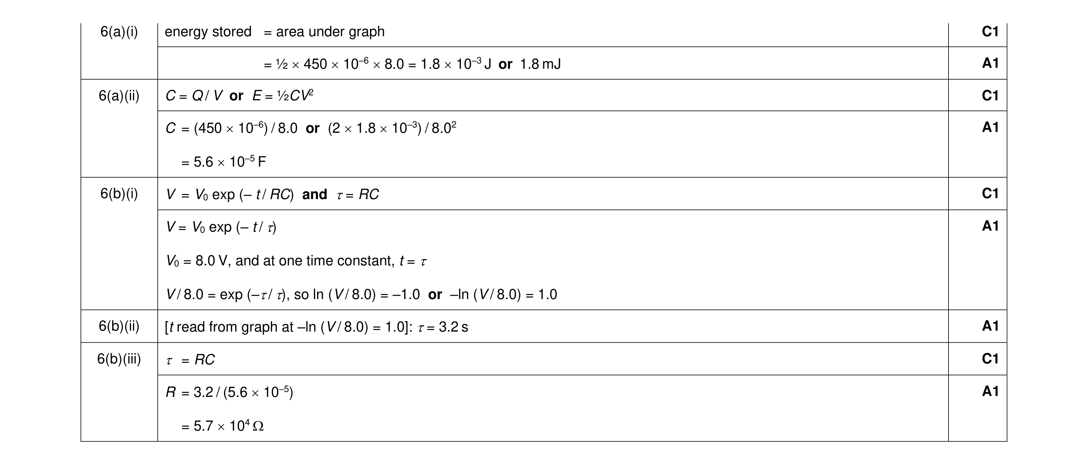 9
9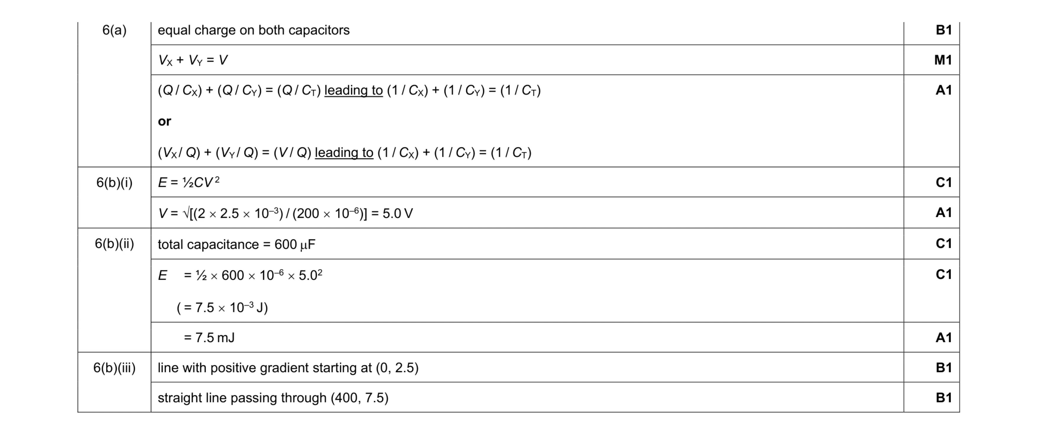 10
10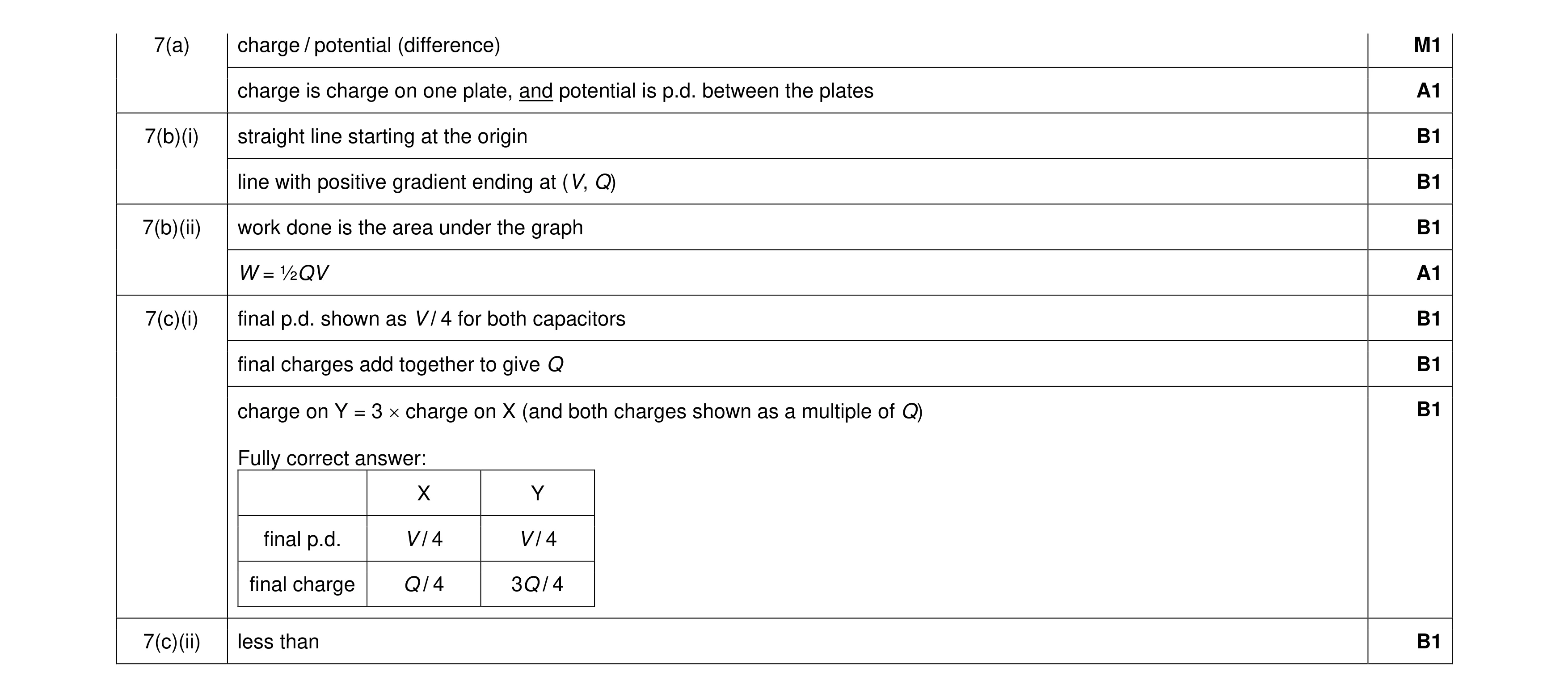 10
10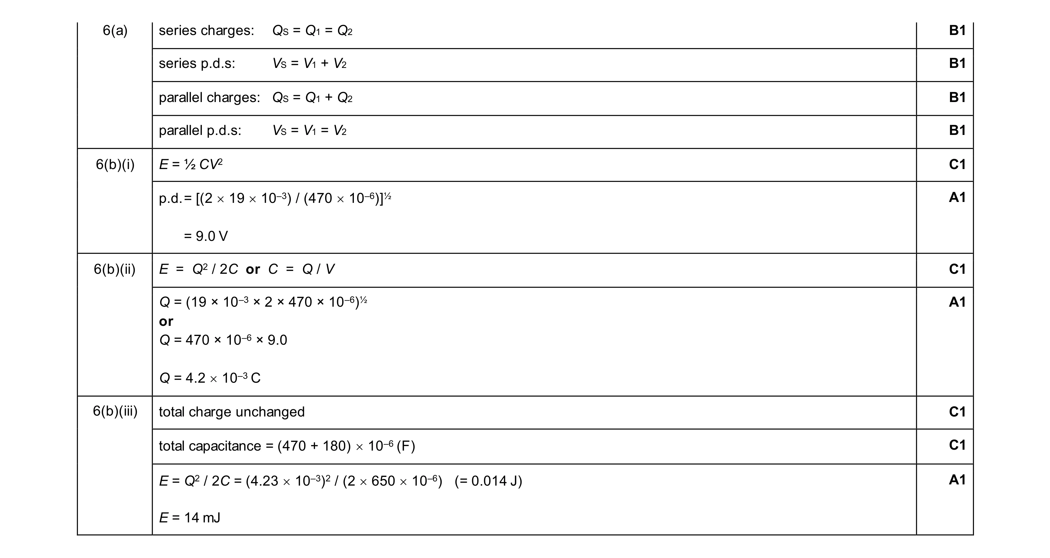 11
11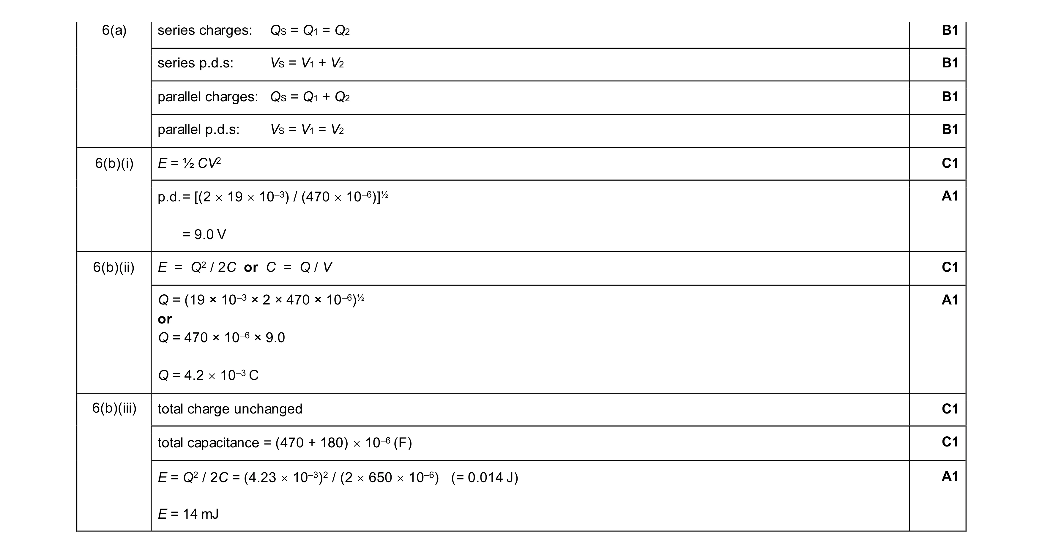 11
11