Cambridge IGCSE Physics 0625 — 2016 Oct/Nov Paper 5 · Variant 2
0625/52/O/N/16 · 40 marks · ≈45 min
The question paper and its mark scheme, free to read here and free to download. This is Cambridge’s own paper, exactly as it was sat.
Question paper12 pages
Mark scheme5 pages
Answers below. Sit the paper first if you are practising.
Paper as text
Question paper, page 1
This document consists of 11 printed pages and 1 blank page. DC (NH/JG) 115584/2 © UCLES 2016 [Turn over * 4 3 7 4 1 4 9 4 3 3 * PHYSICS 0625/52 Paper 5 Practical Test October/November 2016 1 hour 15 minutes Candidates answer on the Question Paper. Additional Materials: As listed in the Confidential Instructions. READ THESE INSTRUCTIONS FIRST Write your Centre number, candidate number and name in the spaces at the top of the page. Write in dark blue or black pen. You may use an HB pencil for any diagrams, graphs or rough working. Do not use staples, paper clips, glue or correction fluid. DO NOT WRITE IN ANY BARCODES. Answer all questions. You are advised to spend about 20 minutes on each of questions 1 to 3, and 15 minutes on question 4. Electronic calculators may be used. You may lose marks if you do not show your working or if you do not use appropriate units. At the end of the examination, fasten all your work securely together. The number of marks is given in brackets [ ] at the end of each question or part question. The syllabus is approved for use in England, Wales and Northern Ireland as a Cambridge International Level 1/Level 2 Certificate. Cambridge International Examinations Cambridge International General Certificate of Secondary Education For Examiner’s Use 1 2 3 4 Total
Question paper, page 2
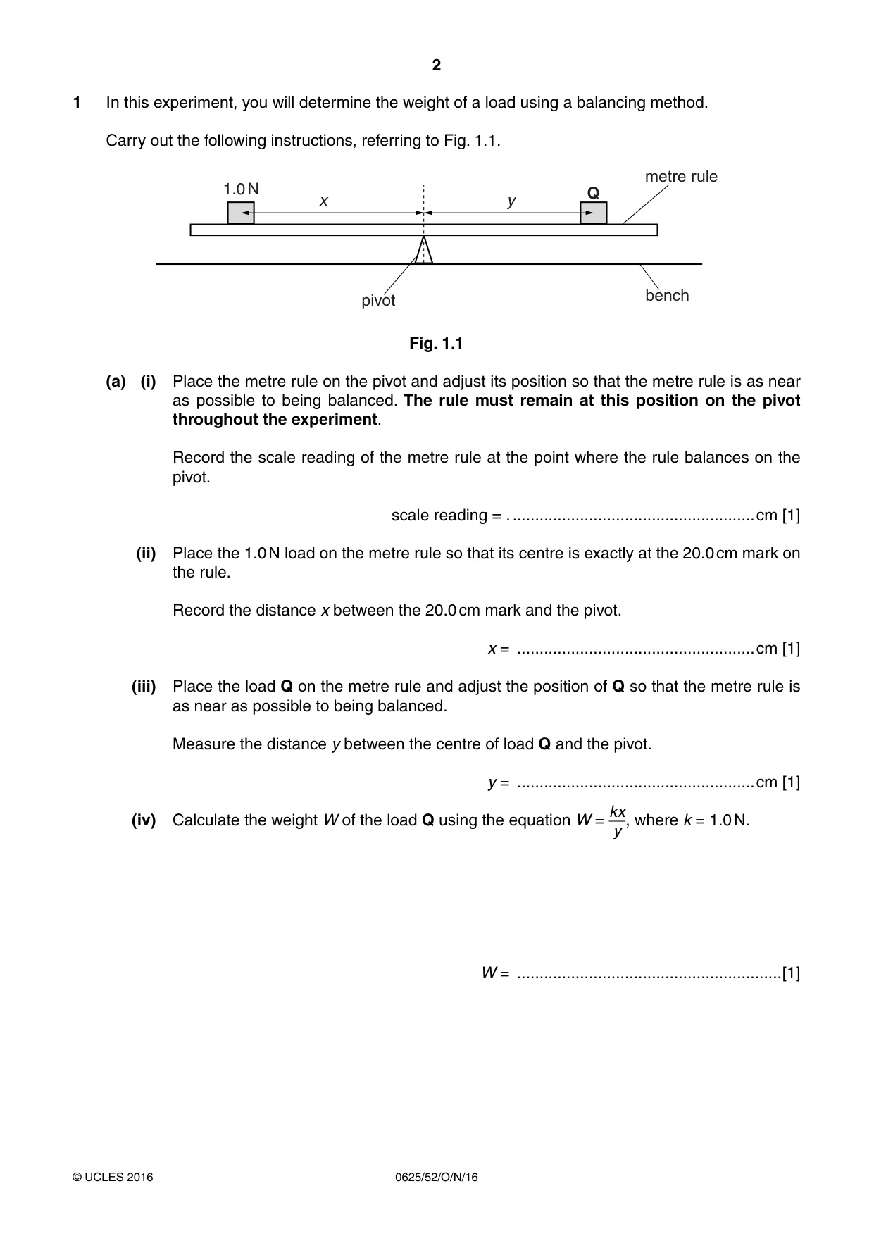
2 0625/52/O/N/16 © UCLES 2016 1 In this experiment, you will determine the weight of a load using a balancing method. Carry out the following instructions, referring to Fig. 1.1. 1.0 N x y Q metre rule bench pivot Fig. 1.1 (a) (i) Place the metre rule on the pivot and adjust its position so that the metre rule is as near as possible to being balanced. The rule must remain at this position on the pivot throughout the experiment. Record the scale reading of the metre rule at the point where the rule balances on the pivot. scale reading = . …cm [1] (ii) Place the 1.0 N load on the metre rule so that its centre is exactly at the 20.0 cm mark on the rule. Record the distance x between the 20.0 cm mark and the pivot. x = …cm [1] (iii) Place the load Q on the metre rule and adjust the position of Q so that the metre rule is as near as possible to being balanced. Measure the distance y between the centre of load Q and the pivot. y = …cm [1] (iv) Calculate the weight W of the load Q using the equation W = kx y , where k = 1.0 N. W = …[1]
Question paper, page 3
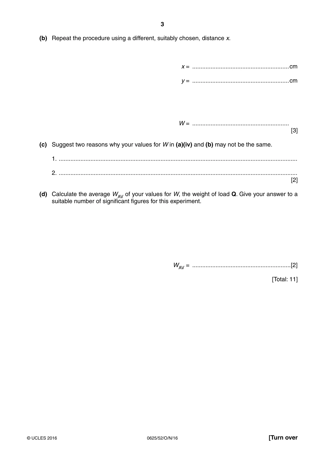
3 0625/52/O/N/16 © UCLES 2016 [Turn over (b) Repeat the procedure using a different, suitably chosen, distance x. x = …cm y = …cm W = … [3] (c) Suggest two reasons why your values for W in (a)(iv) and (b) may not be the same. 1. … 2. … [2] (d) Calculate the average WAV of your values for W, the weight of load Q. Give your answer to a suitable number of significant figures for this experiment. WAV = …[2] [Total: 11]
Question paper, page 4
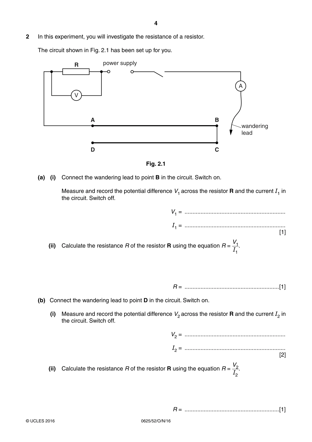
4 0625/52/O/N/16 © UCLES 2016 2 In this experiment, you will investigate the resistance of a resistor. The circuit shown in Fig. 2.1 has been set up for you. R A D B C V A power supply wandering lead Fig. 2.1 (a) (i) Connect the wandering lead to point B in the circuit. Switch on. Measure and record the potential difference V1 across the resistor R and the current I1 in the circuit. Switch off. V1 = … I1 = … [1] (ii) Calculate the resistance R of the resistor R using the equation R = V1 I1 . R = …[1] (b) Connect the wandering lead to point D in the circuit. Switch on. (i) Measure and record the potential difference V2 across the resistor R and the current I2 in the circuit. Switch off. V2 = … I2 = … [2] (ii) Calculate the resistance R of the resistor R using the equation R = V2 I2 . R = …[1]
Question paper, page 5
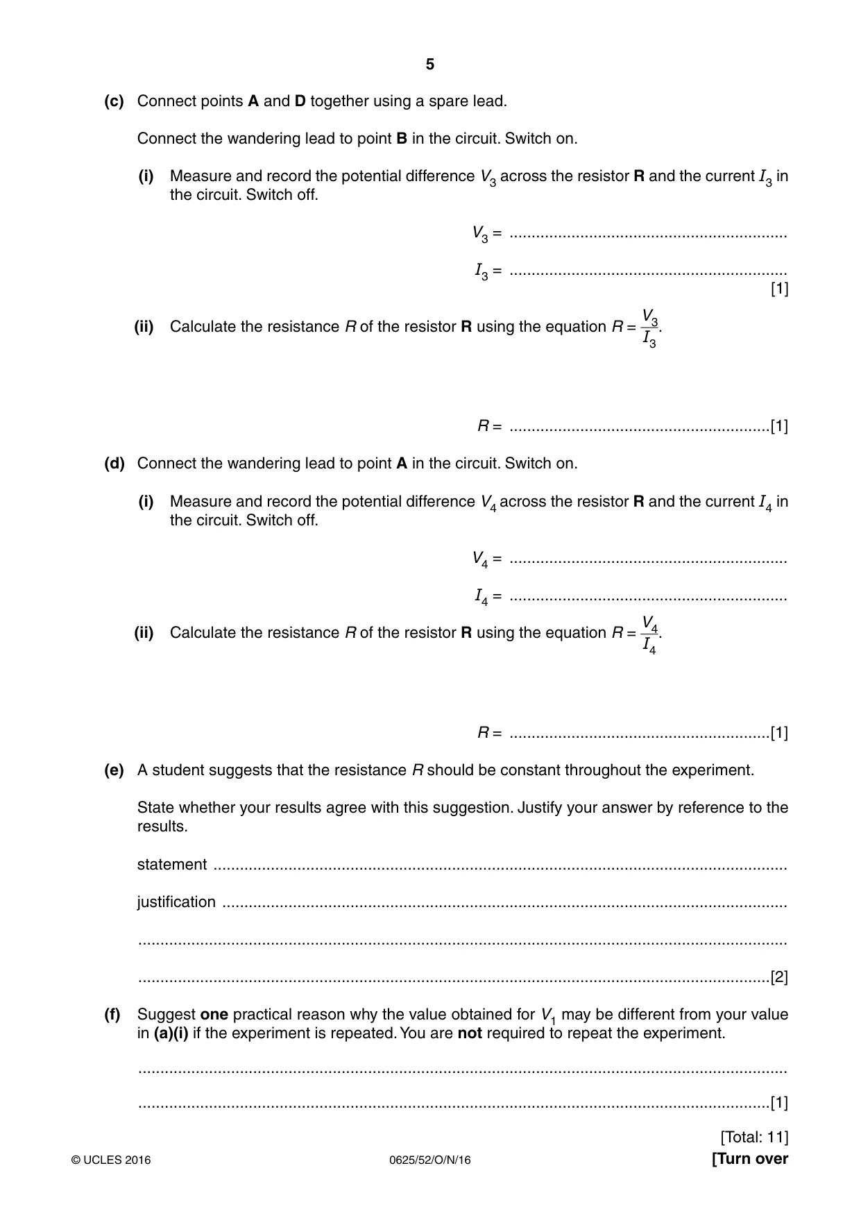
5 0625/52/O/N/16 © UCLES 2016 [Turn over (c) Connect points A and D together using a spare lead. Connect the wandering lead to point B in the circuit. Switch on. (i) Measure and record the potential difference V3 across the resistor R and the current I3 in the circuit. Switch off. V3 = … I3 = … [1] (ii) Calculate the resistance R of the resistor R using the equation R = V3 I3 . R = …[1] (d) Connect the wandering lead to point A in the circuit. Switch on. (i) Measure and record the potential difference V4 across the resistor R and the current I4 in the circuit. Switch off. V4 = … I4 = … (ii) Calculate the resistance R of the resistor R using the equation R = V4 I4 . R = …[1] (e) A student suggests that the resistance R should be constant throughout the experiment. State whether your results agree with this suggestion. Justify your answer by reference to the results. statement … justification … … …[2] (f) Suggest one practical reason why the value obtained for V1 may be different from your value in (a)(i) if the experiment is repeated. You are not required to repeat the experiment. … …[1] [Total: 11]
Question paper, page 6
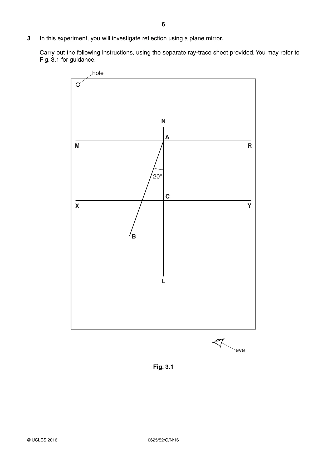
6 0625/52/O/N/16 © UCLES 2016 3 In this experiment, you will investigate reflection using a plane mirror. Carry out the following instructions, using the separate ray-trace sheet provided. You may refer to Fig. 3.1 for guidance. 20° B C A L N M R Y X eye hole Fig. 3.1
Question paper, page 7
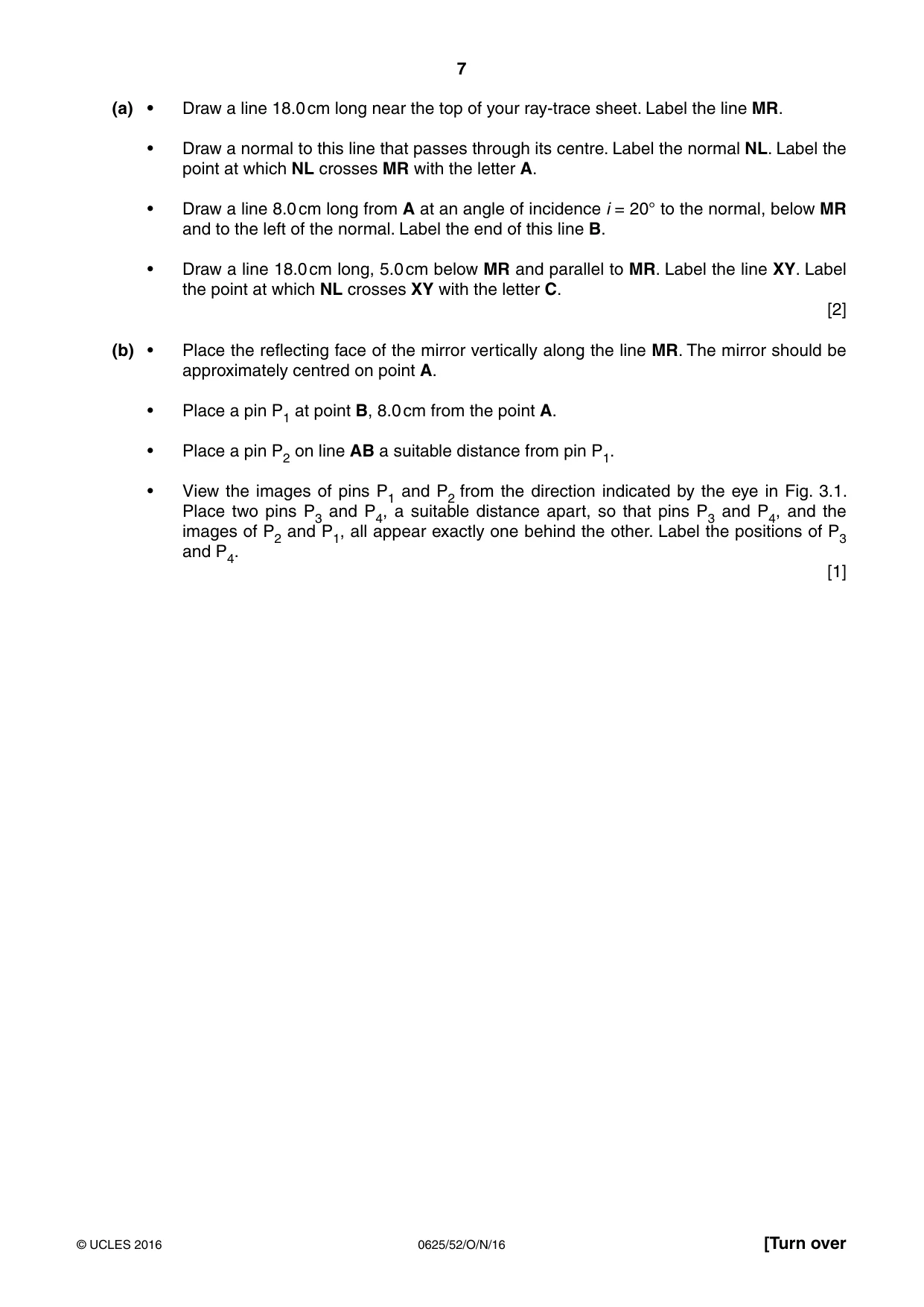
7 0625/52/O/N/16 © UCLES 2016 [Turn over (a) • Draw a line 18.0 cm long near the top of your ray-trace sheet. Label the line MR. • Draw a normal to this line that passes through its centre. Label the normal NL. Label the point at which NL crosses MR with the letter A. • Draw a line 8.0 cm long from A at an angle of incidence i = 20° to the normal, below MR and to the left of the normal. Label the end of this line B. • Draw a line 18.0 cm long, 5.0 cm below MR and parallel to MR. Label the line XY. Label the point at which NL crosses XY with the letter C. [2] (b) • Place the reflecting face of the mirror vertically along the line MR. The mirror should be approximately centred on point A. • Place a pin P1 at point B, 8.0 cm from the point A. • Place a pin P2 on line AB a suitable distance from pin P1. • View the images of pins P1 and P2 from the direction indicated by the eye in Fig. 3.1. Place two pins P3 and P4, a suitable distance apart, so that pins P3 and P4, and the images of P2 and P1, all appear exactly one behind the other. Label the positions of P3 and P4. [1]
Question paper, page 8
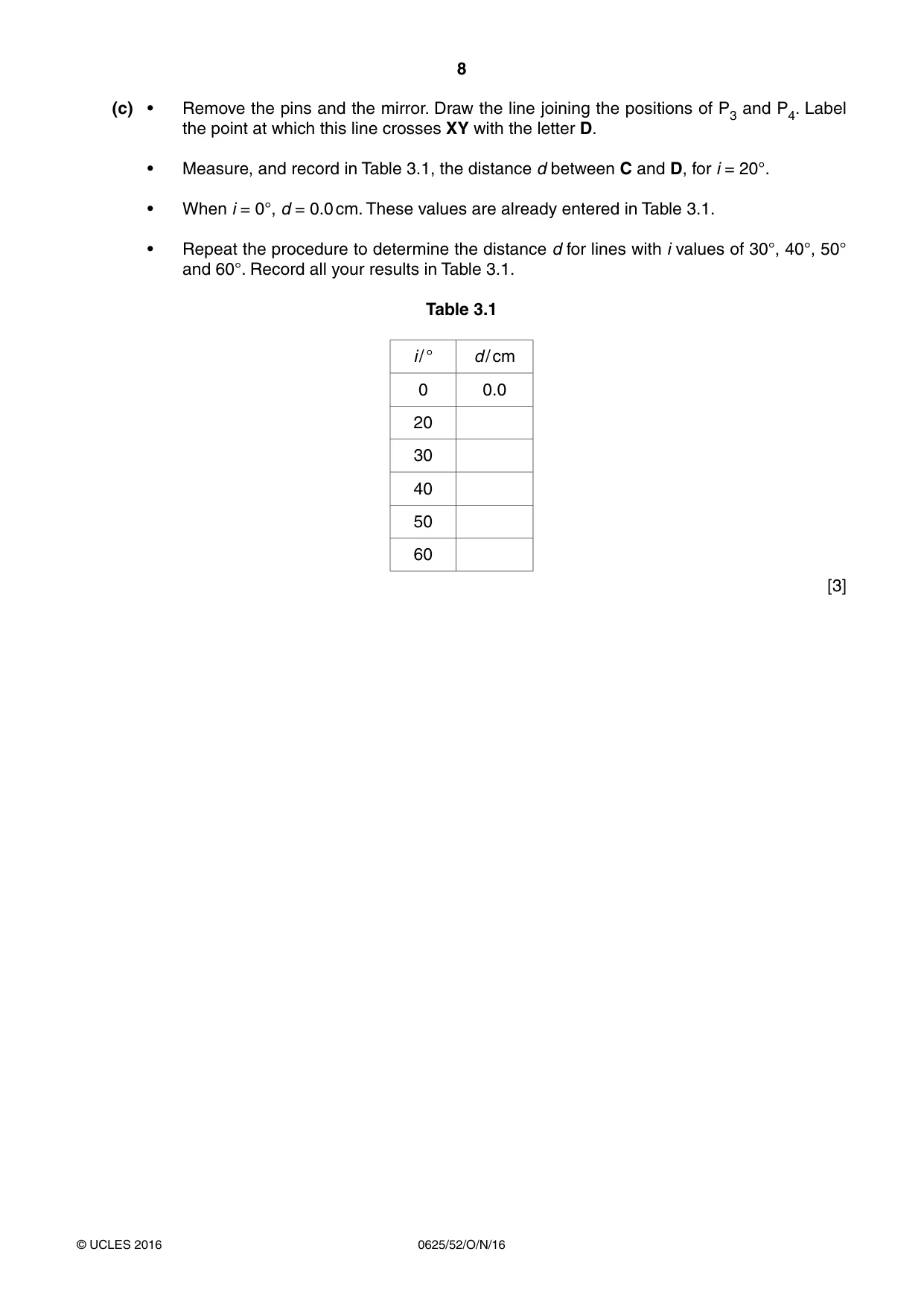
8 0625/52/O/N/16 © UCLES 2016 (c) • Remove the pins and the mirror. Draw the line joining the positions of P3 and P4. Label the point at which this line crosses XY with the letter D. • Measure, and record in Table 3.1, the distance d between C and D, for i = 20°. • When i = 0°, d = 0.0 cm. These values are already entered in Table 3.1. • Repeat the procedure to determine the distance d for lines with i values of 30°, 40°, 50° and 60°. Record all your results in Table 3.1. Table 3.1 i / ° d / cm 0 0.0 20 30 40 50 60 [3]
Question paper, page 9
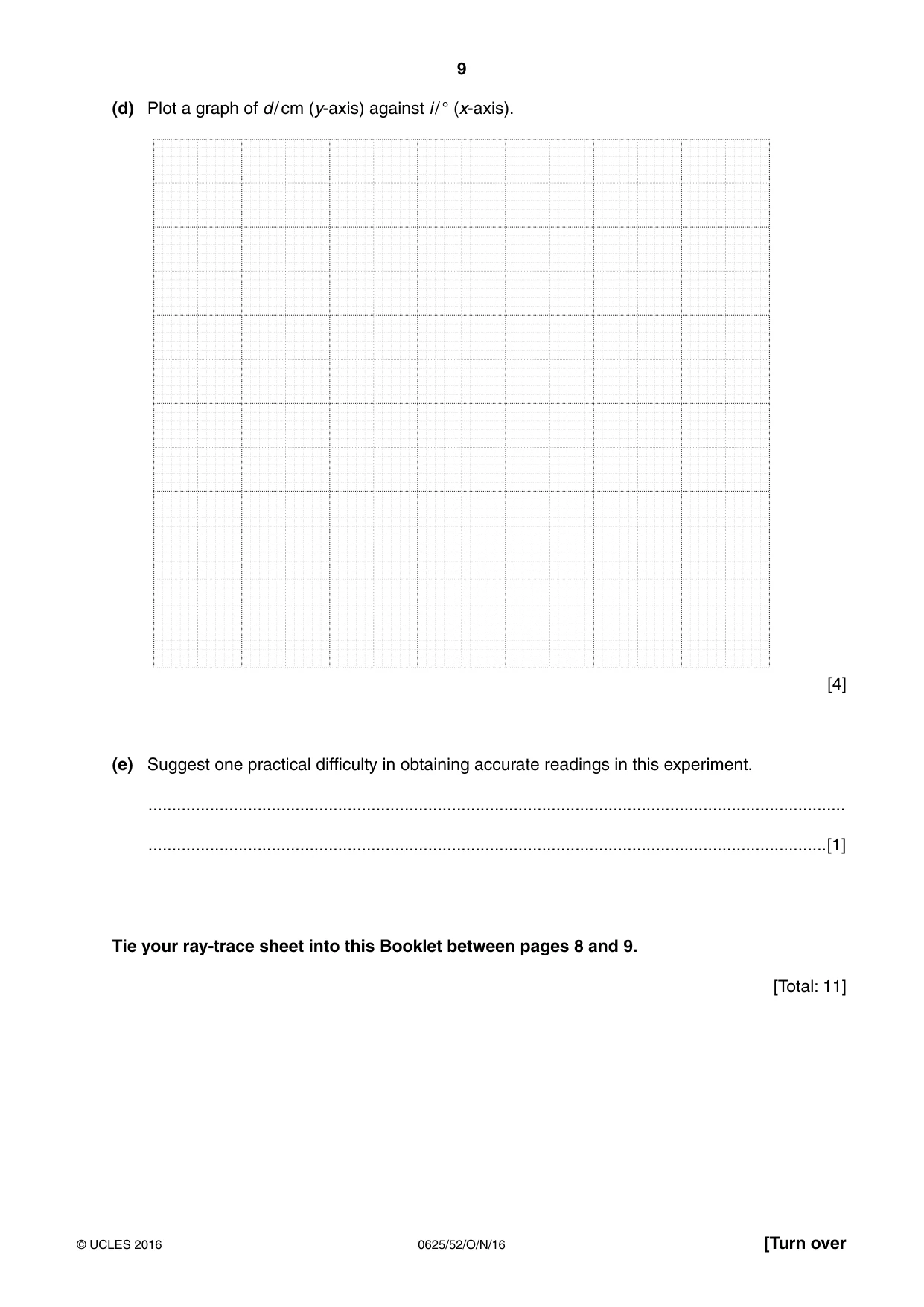
9 0625/52/O/N/16 © UCLES 2016 [Turn over (d) Plot a graph of d / cm (y-axis) against i / ° (x-axis). [4] (e) Suggest one practical difficulty in obtaining accurate readings in this experiment. … …[1] Tie your ray-trace sheet into this Booklet between pages 8 and 9. [Total: 11]
Question paper, page 10
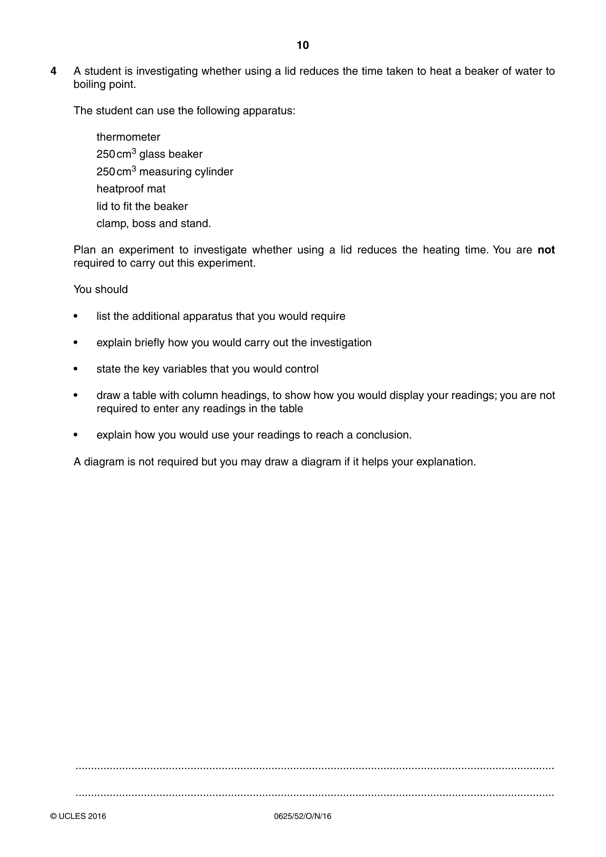
10 0625/52/O/N/16 © UCLES 2016 4 A student is investigating whether using a lid reduces the time taken to heat a beaker of water to boiling point. The student can use the following apparatus: thermometer 250 cm3 glass beaker 250 cm3 measuring cylinder heatproof mat lid to fit the beaker clamp, boss and stand. Plan an experiment to investigate whether using a lid reduces the heating time. You are not required to carry out this experiment. You should • list the additional apparatus that you would require • explain briefly how you would carry out the investigation • state the key variables that you would control • draw a table with column headings, to show how you would display your readings; you are not required to enter any readings in the table • explain how you would use your readings to reach a conclusion. A diagram is not required but you may draw a diagram if it helps your explanation. … …
Question paper, page 11
11 0625/52/O/N/16 © UCLES 2016 … … … … … … … … … … … … … … … … … … … … … … … … … … …[7] [Total: 7]
Question paper, page 12
12 0625/52/O/N/16 © UCLES 2016 Permission to reproduce items where third-party owned material protected by copyright is included has been sought and cleared where possible. Every reasonable effort has been made by the publisher (UCLES) to trace copyright holders, but if any items requiring clearance have unwittingly been included, the publisher will be pleased to make amends at the earliest possible opportunity. To avoid the issue of disclosure of answer-related information to candidates, all copyright acknowledgements are reproduced online in the Cambridge International Examinations Copyright Acknowledgements Booklet. This is produced for each series of examinations and is freely available to download at www.cie.org.uk after the live examination series. Cambridge International Examinations is part of the Cambridge Assessment Group. Cambridge Assessment is the brand name of University of Cambridge Local Examinations Syndicate (UCLES), which is itself a department of the University of Cambridge. BLANK PAGE
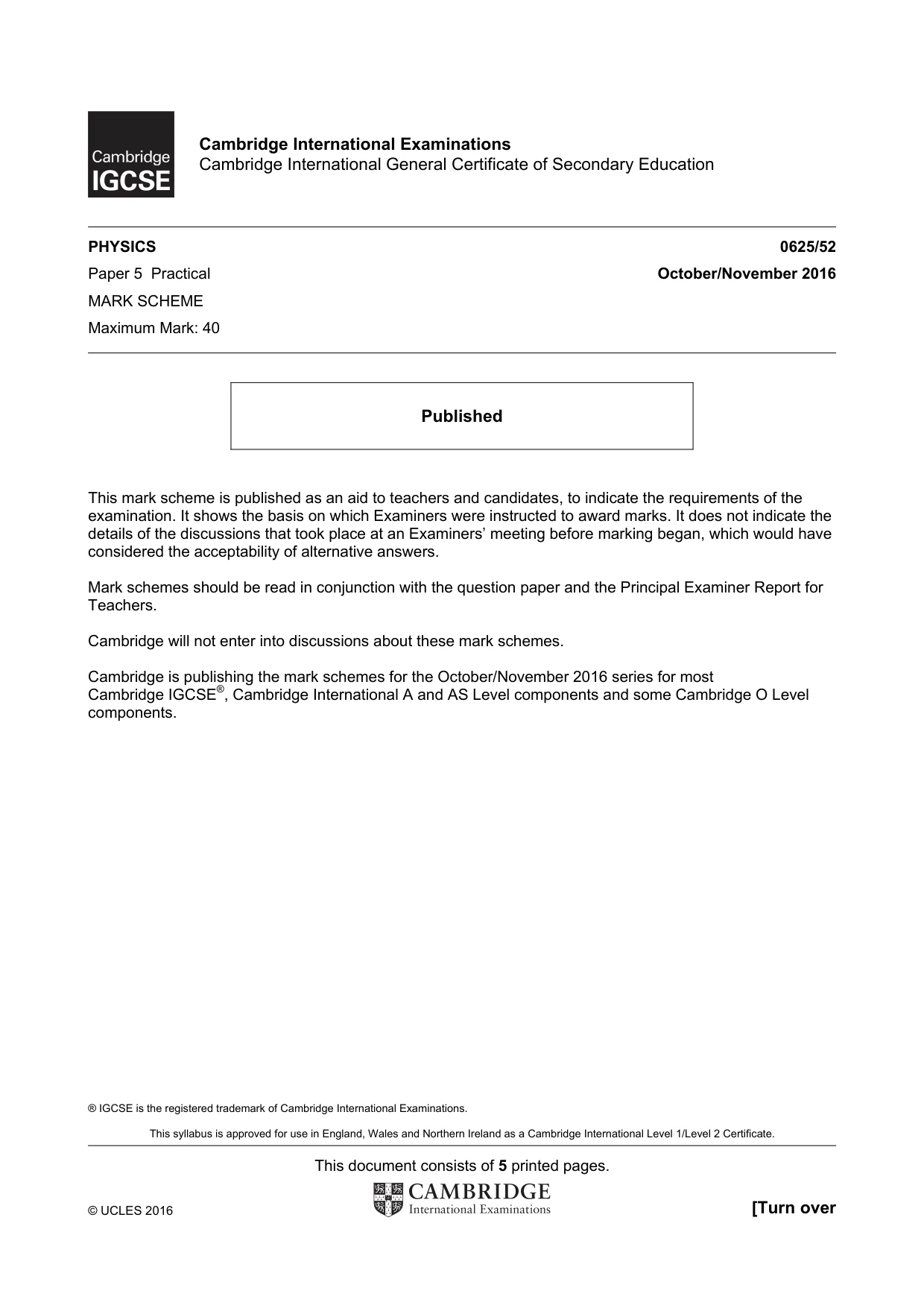
Mark scheme, page 1
® IGCSE is the registered trademark of Cambridge International Examinations. This syllabus is approved for use in England, Wales and Northern Ireland as a Cambridge International Level 1/Level 2 Certificate. This document consists of 5 printed pages. © UCLES 2016 [Turn over Cambridge International Examinations Cambridge International General Certificate of Secondary Education PHYSICS 0625/52 Paper 5 Practical October/November 2016 MARK SCHEME Maximum Mark: 40 Published This mark scheme is published as an aid to teachers and candidates, to indicate the requirements of the examination. It shows the basis on which Examiners were instructed to award marks. It does not indicate the details of the discussions that took place at an Examiners’ meeting before marking began, which would have considered the acceptability of alternative answers. Mark schemes should be read in conjunction with the question paper and the Principal Examiner Report for Teachers. Cambridge will not enter into discussions about these mark schemes. Cambridge is publishing the mark schemes for the October/November 2016 series for most Cambridge IGCSE®, Cambridge International A and AS Level components and some Cambridge O Level components.
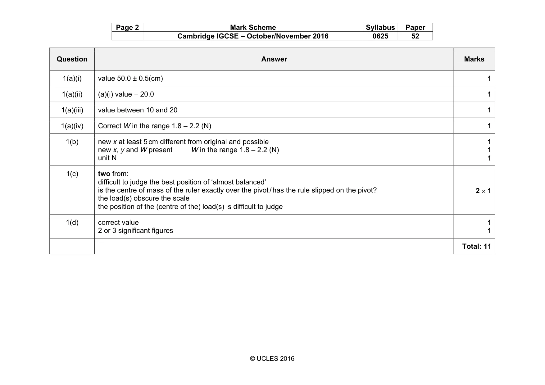
Mark scheme, page 2
Page 2 Mark Scheme Syllabus Paper Cambridge IGCSE – October/November 2016 0625 52 © UCLES 2016 Question Answer Marks 1(a)(i) value 50.0 ± 0.5(cm) 1 1(a)(ii) (a)(i) value − 20.0 1 1(a)(iii) value between 10 and 20 1 1(a)(iv) Correct W in the range 1.8 – 2.2 (N) 1 1(b) new x at least 5 cm different from original and possible new x, y and W present W in the range 1.8 – 2.2 (N) unit N 1 1 1 1(c) two from: difficult to judge the best position of ‘almost balanced’ is the centre of mass of the ruler exactly over the pivot / has the rule slipped on the pivot? the load(s) obscure the scale the position of the (centre of the) load(s) is difficult to judge 2 × 1 1(d) correct value 2 or 3 significant figures 1 1 Total: 11
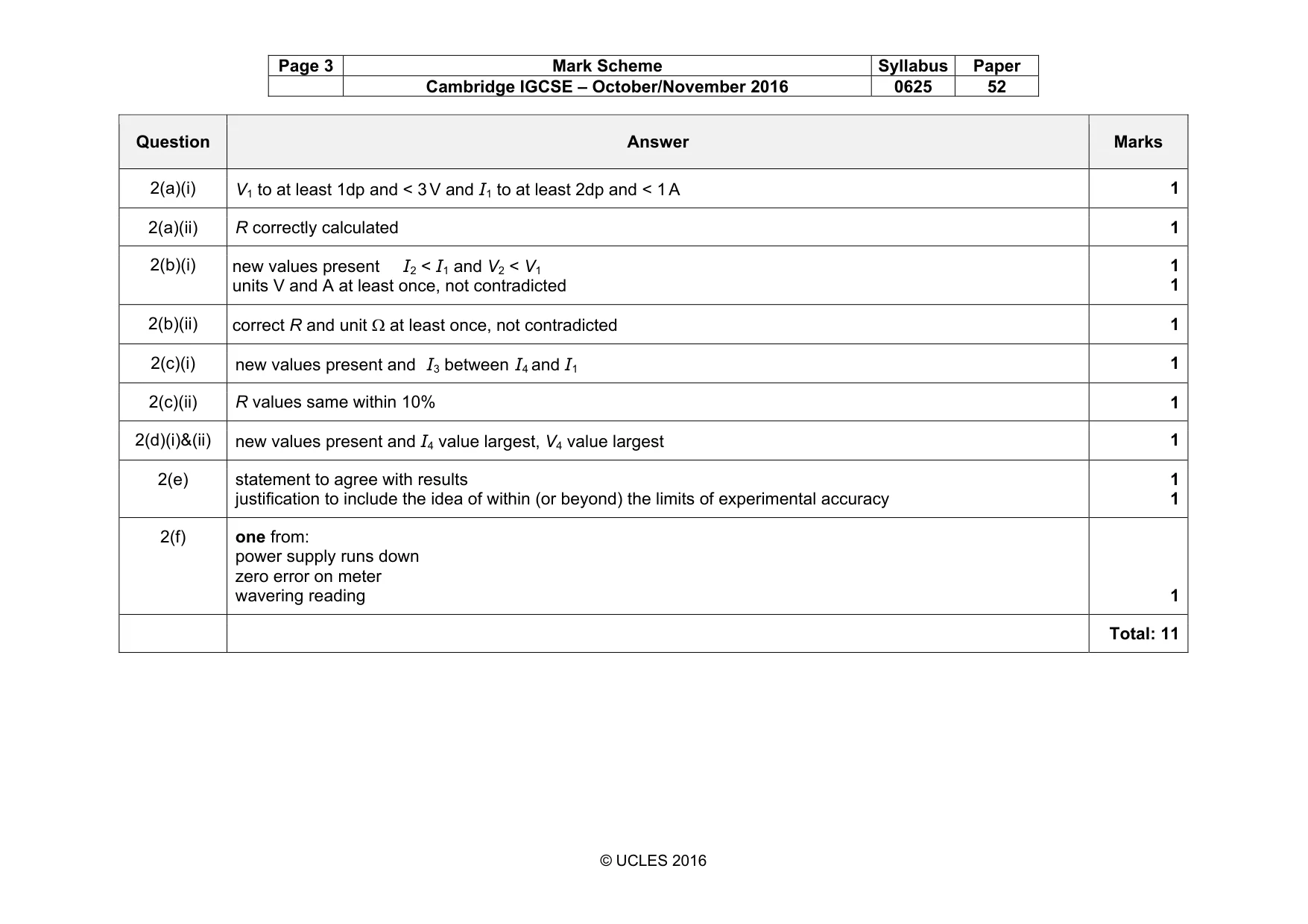
Mark scheme, page 3
Page 3 Mark Scheme Syllabus Paper Cambridge IGCSE – October/November 2016 0625 52 © UCLES 2016 Question Answer Marks 2(a)(i) V1 to at least 1dp and < 3 V and I1 to at least 2dp and < 1 A 1 2(a)(ii) R correctly calculated 1 2(b)(i) new values present I2 < I1 and V2 < V1 units V and A at least once, not contradicted 1 1 2(b)(ii) correct R and unit Ω at least once, not contradicted 1 2(c)(i) new values present and I3 between I4 and I1 1 2(c)(ii) R values same within 10% 1 2(d)(i)&(ii) new values present and I4 value largest, V4 value largest 1 2(e) statement to agree with results justification to include the idea of within (or beyond) the limits of experimental accuracy 1 1 2(f) one from: power supply runs down zero error on meter wavering reading 1 Total: 11
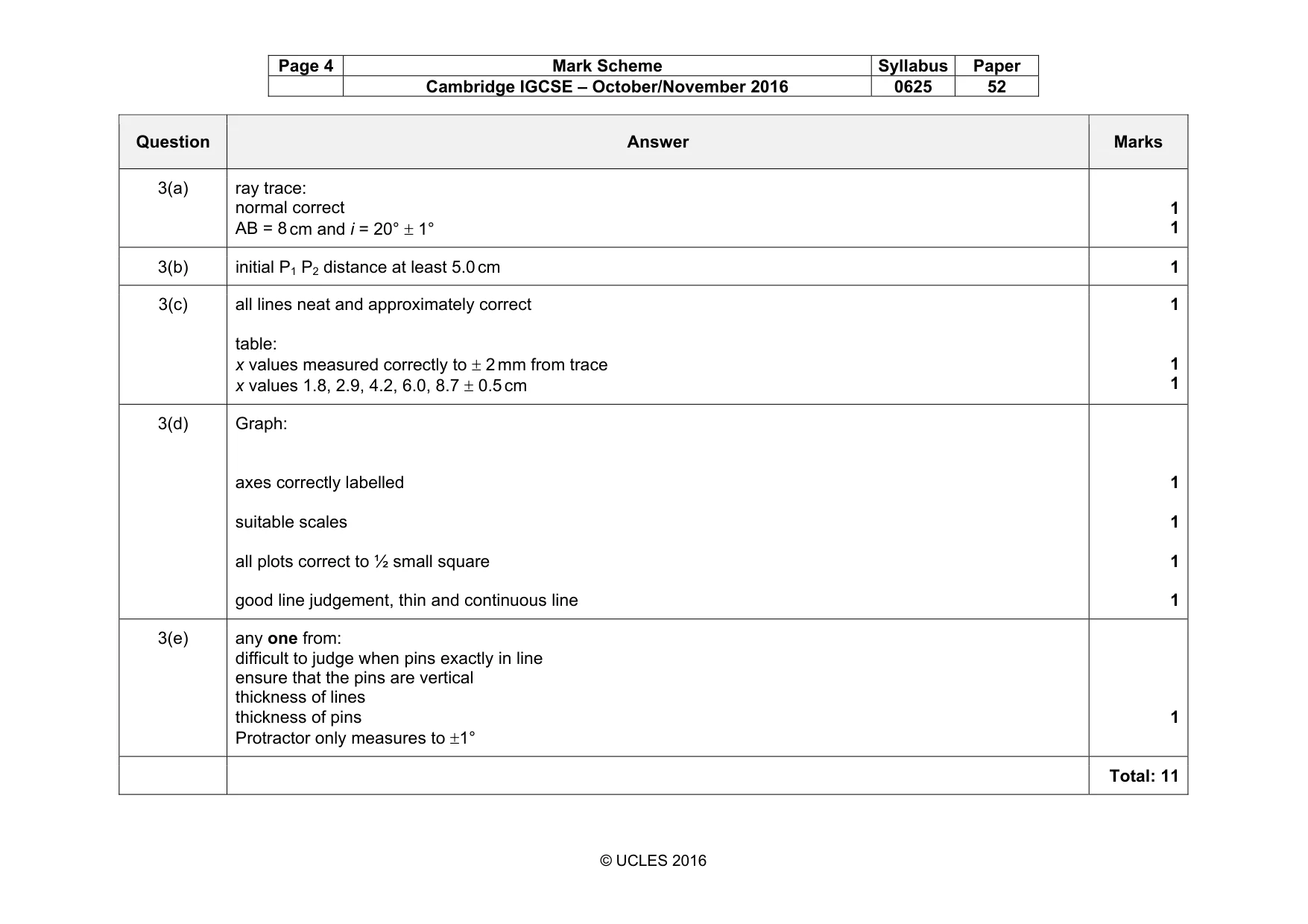
Mark scheme, page 4
Page 4 Mark Scheme Syllabus Paper Cambridge IGCSE – October/November 2016 0625 52 © UCLES 2016 Question Answer Marks 3(a) ray trace: normal correct AB = 8 cm and i = 20° ± 1° 1 1 3(b) initial P1 P2 distance at least 5.0 cm 1 3(c) all lines neat and approximately correct table: x values measured correctly to ± 2 mm from trace x values 1.8, 2.9, 4.2, 6.0, 8.7 ± 0.5 cm 1 1 1 3(d) Graph: axes correctly labelled suitable scales all plots correct to ½ small square good line judgement, thin and continuous line 1 1 1 1 3(e) any one from: difficult to judge when pins exactly in line ensure that the pins are vertical thickness of lines thickness of pins Protractor only measures to ±1° 1 Total: 11
Mark scheme, page 5
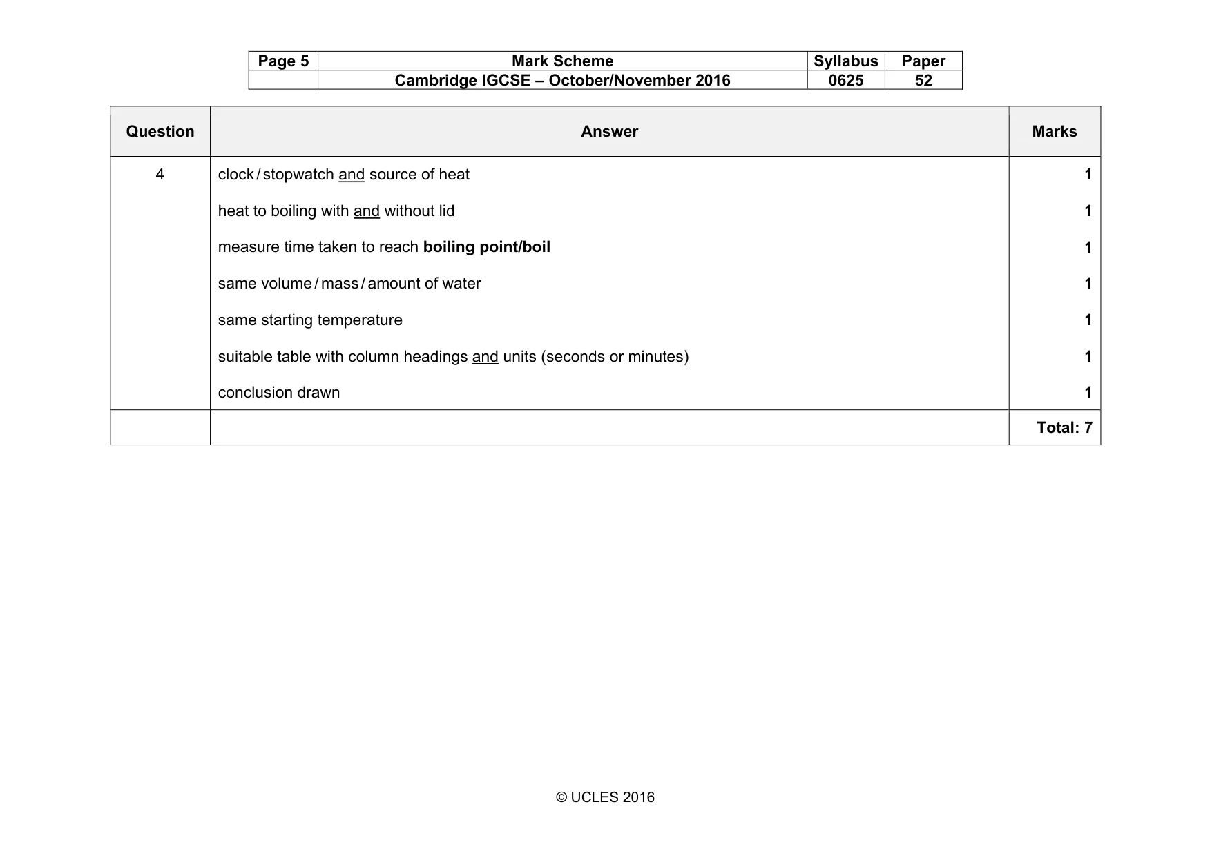
Page 5 Mark Scheme Syllabus Paper Cambridge IGCSE – October/November 2016 0625 52 © UCLES 2016 Question Answer Marks 4 clock / stopwatch and source of heat heat to boiling with and without lid measure time taken to reach boiling point/boil same volume / mass / amount of water same starting temperature suitable table with column headings and units (seconds or minutes) conclusion drawn 1 1 1 1 1 1 1 Total: 7
What you needed in this session
Cambridge’s own grade thresholds for 2016 Oct/Nov, Paper 5 · Variant 2. A higher threshold means an easier paper — the bar moves with how the cohort did.