Cambridge IGCSE Physics 0625 — 2016 Oct/Nov Paper 5 · Variant 1
0625/51/O/N/16 · 40 marks · ≈45 min
The question paper and its mark scheme, free to read here and free to download. This is Cambridge’s own paper, exactly as it was sat.
Question paper12 pages
Mark scheme5 pages
Answers below. Sit the paper first if you are practising.
Paper as text
Question paper, page 1
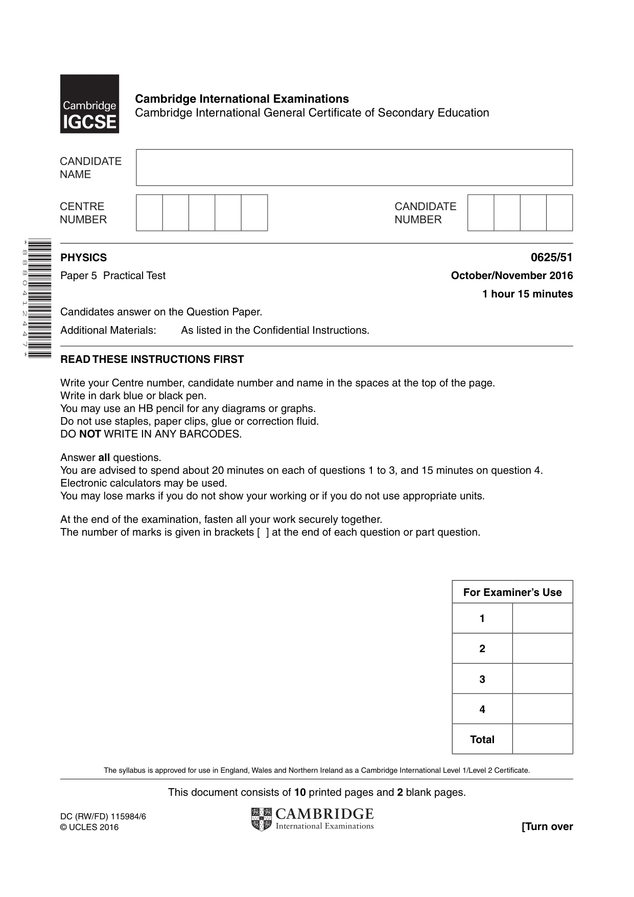
This document consists of 10 printed pages and 2 blank pages. DC (RW/FD) 115984/6 © UCLES 2016 [Turn over Cambridge International Examinations Cambridge International General Certificate of Secondary Education * 8 8 8 0 4 1 2 4 4 7 * PHYSICS 0625/51 Paper 5 Practical Test October/November 2016 1 hour 15 minutes Candidates answer on the Question Paper. Additional Materials: As listed in the Confidential Instructions. READ THESE INSTRUCTIONS FIRST Write your Centre number, candidate number and name in the spaces at the top of the page. Write in dark blue or black pen. You may use an HB pencil for any diagrams or graphs. Do not use staples, paper clips, glue or correction fluid. DO NOT WRITE IN ANY BARCODES. Answer all questions. You are advised to spend about 20 minutes on each of questions 1 to 3, and 15 minutes on question 4. Electronic calculators may be used. You may lose marks if you do not show your working or if you do not use appropriate units. At the end of the examination, fasten all your work securely together. The number of marks is given in brackets [ ] at the end of each question or part question. The syllabus is approved for use in England, Wales and Northern Ireland as a Cambridge International Level 1/Level 2 Certificate. For Examiner’s Use 1 2 3 4 Total
Question paper, page 2
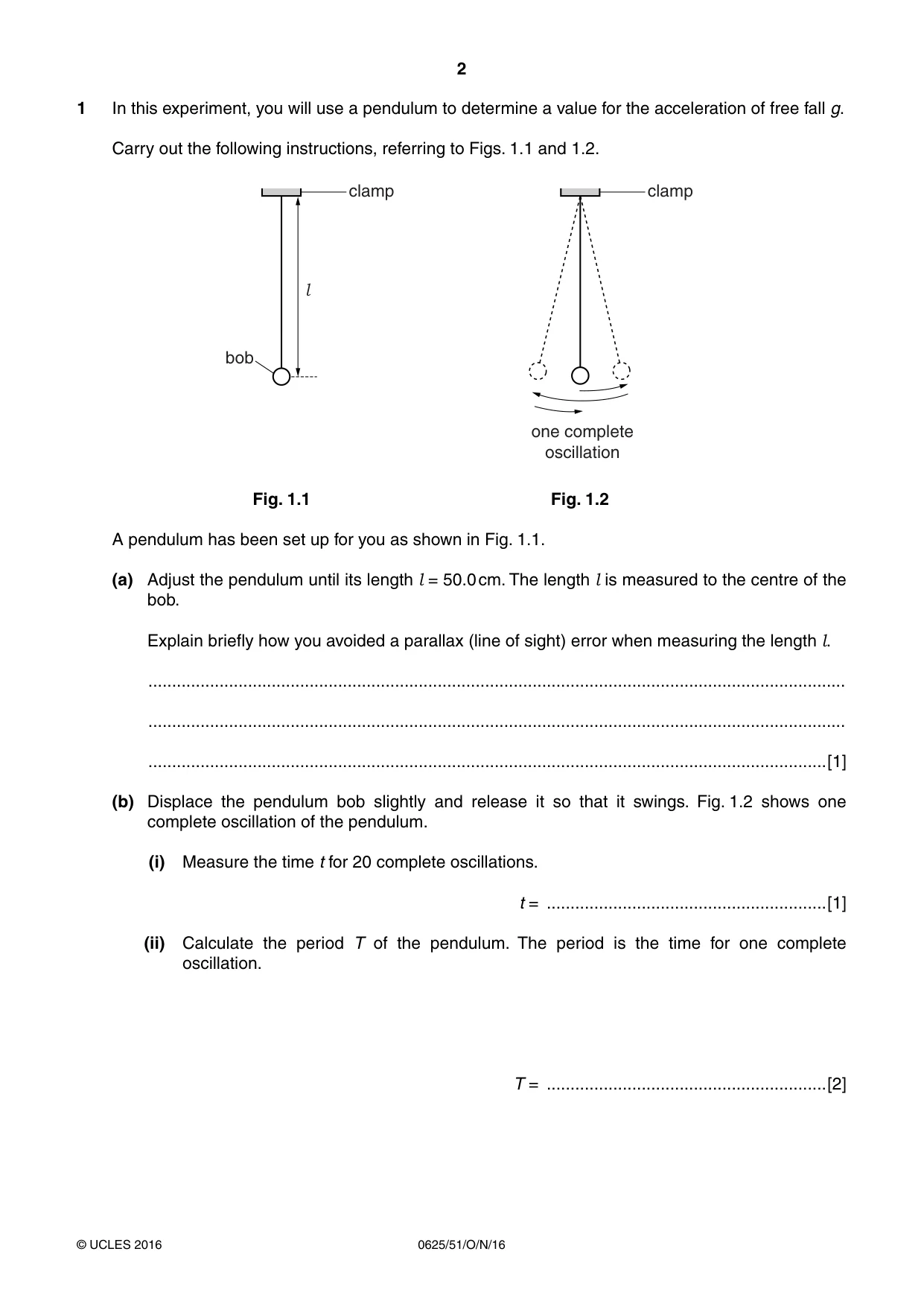
2 0625/51/O/N/16 © UCLES 2016 1 In this experiment, you will use a pendulum to determine a value for the acceleration of free fall g. Carry out the following instructions, referring to Figs. 1.1 and 1.2. bob clamp l clamp one complete oscillation Fig. 1.1 Fig. 1.2 A pendulum has been set up for you as shown in Fig. 1.1. (a) Adjust the pendulum until its length l = 50.0 cm. The length l is measured to the centre of the bob. Explain briefly how you avoided a parallax (line of sight) error when measuring the length l. … … …[1] (b) Displace the pendulum bob slightly and release it so that it swings. Fig. 1.2 shows one complete oscillation of the pendulum. (i) Measure the time t for 20 complete oscillations. t = …[1] (ii) Calculate the period T of the pendulum. The period is the time for one complete oscillation. T = …[2]
Question paper, page 3
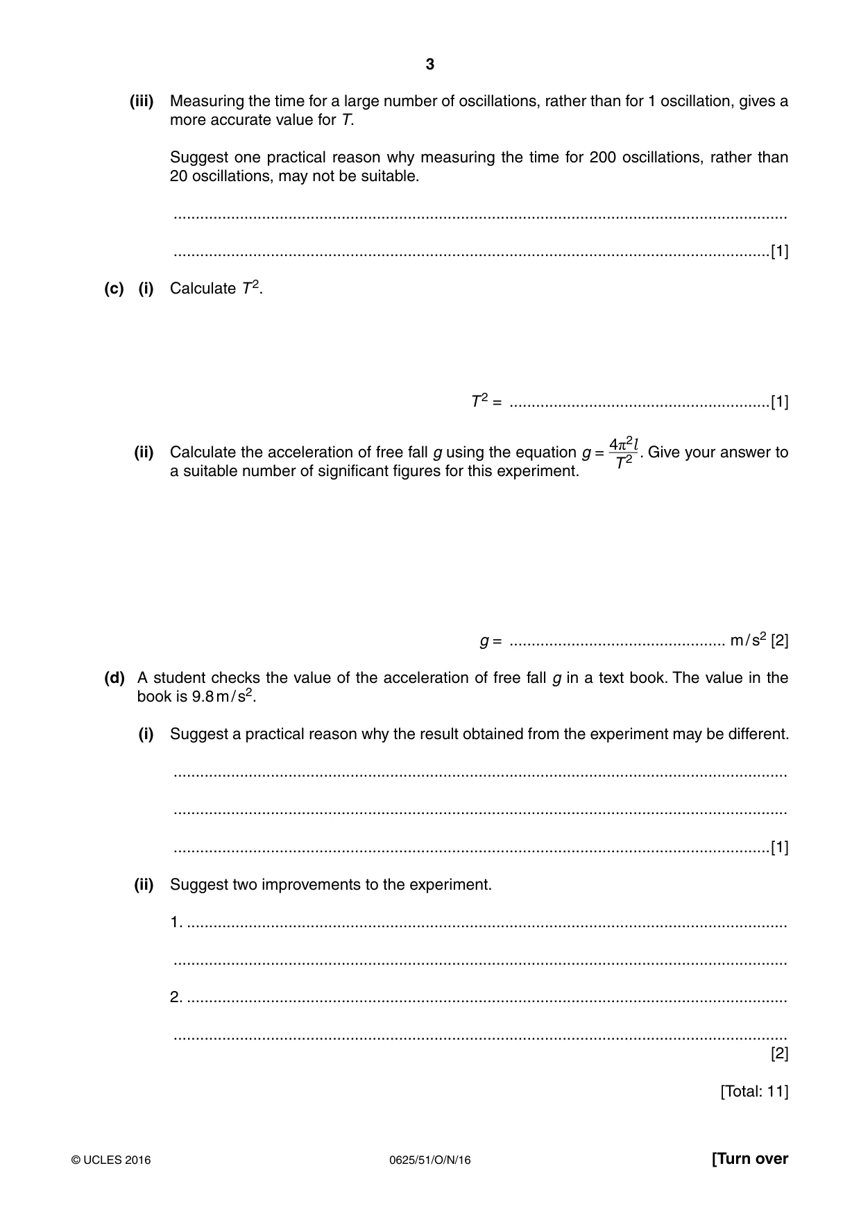
3 0625/51/O/N/16 © UCLES 2016 [Turn over (iii) Measuring the time for a large number of oscillations, rather than for 1 oscillation, gives a more accurate value for T. Suggest one practical reason why measuring the time for 200 oscillations, rather than 20 oscillations, may not be suitable. … …[1] (c) (i) Calculate T 2. T 2 = …[1] (ii) Calculate the acceleration of free fall g using the equation g = 4π2l T 2 . Give your answer to a suitable number of significant figures for this experiment. g = … m / s2 [2] (d) A student checks the value of the acceleration of free fall g in a text book. The value in the book is 9.8 m / s2. (i) Suggest a practical reason why the result obtained from the experiment may be different. … … …[1] (ii) Suggest two improvements to the experiment. 1. … … 2. … … [2] [Total: 11]
Question paper, page 4
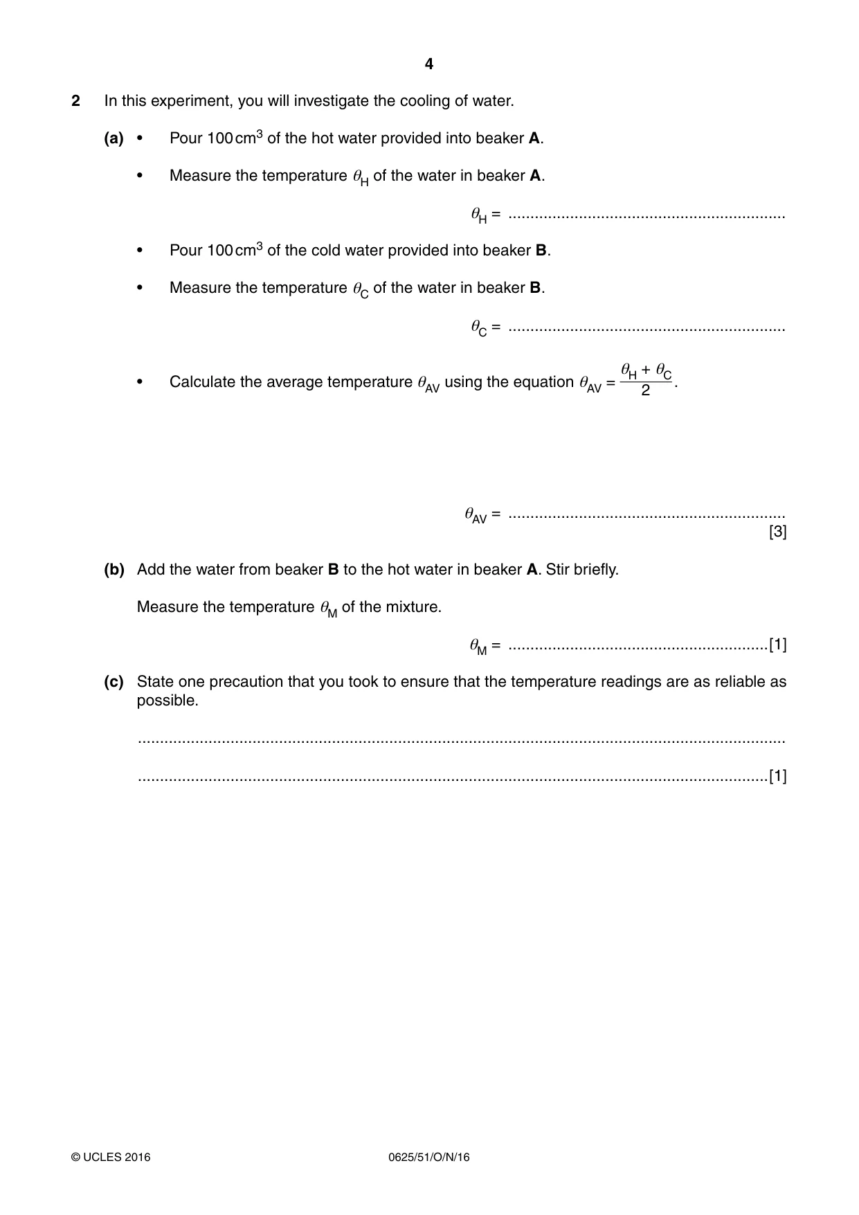
4 0625/51/O/N/16 © UCLES 2016 2 In this experiment, you will investigate the cooling of water. (a) • Pour 100 cm3 of the hot water provided into beaker A. • Measure the temperature θH of the water in beaker A. θH = … • Pour 100 cm3 of the cold water provided into beaker B. • Measure the temperature θC of the water in beaker B. θC = … • Calculate the average temperature θAV using the equation θAV = θH + θC 2 . θAV = … [3] (b) Add the water from beaker B to the hot water in beaker A. Stir briefly. Measure the temperature θM of the mixture. θM = …[1] (c) State one precaution that you took to ensure that the temperature readings are as reliable as possible. … …[1]
Question paper, page 5
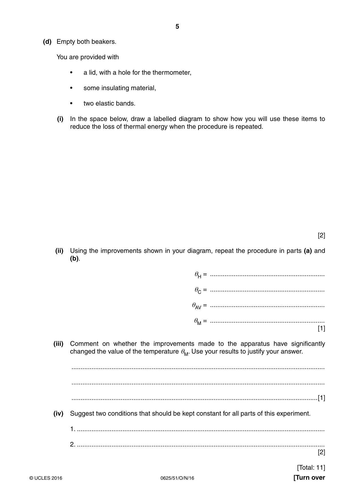
5 0625/51/O/N/16 © UCLES 2016 [Turn over (d) Empty both beakers. You are provided with • a lid, with a hole for the thermometer, • some insulating material, • two elastic bands. (i) In the space below, draw a labelled diagram to show how you will use these items to reduce the loss of thermal energy when the procedure is repeated. [2] (ii) Using the improvements shown in your diagram, repeat the procedure in parts (a) and (b). θH = … θC = … θAV = … θM = … [1] (iii) Comment on whether the improvements made to the apparatus have significantly changed the value of the temperature θM. Use your results to justify your answer. … … …[1] (iv) Suggest two conditions that should be kept constant for all parts of this experiment. 1. … 2. … [2] [Total: 11]
Question paper, page 6
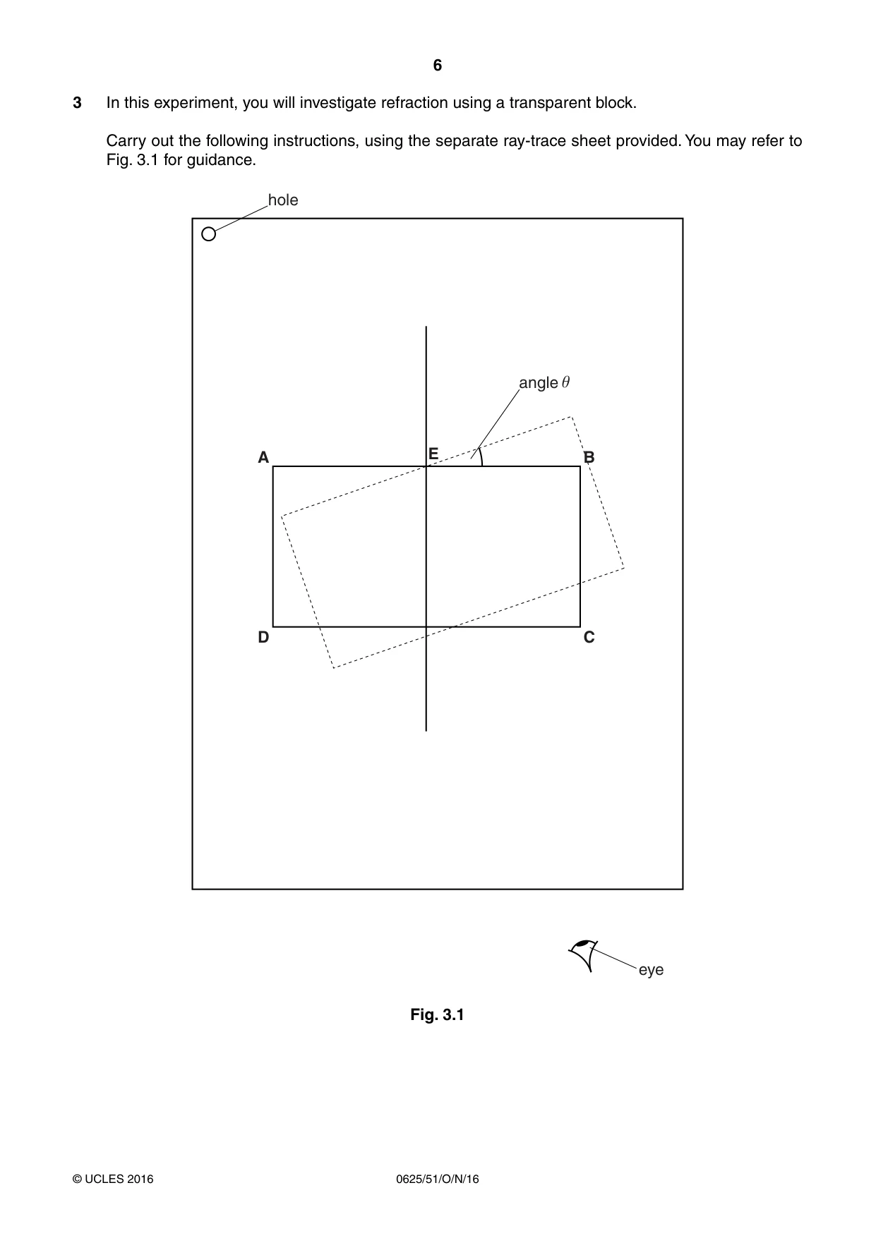
6 0625/51/O/N/16 © UCLES 2016 3 In this experiment, you will investigate refraction using a transparent block. Carry out the following instructions, using the separate ray-trace sheet provided. You may refer to Fig. 3.1 for guidance. hole angle eye A D B E C e Fig. 3.1
Question paper, page 7
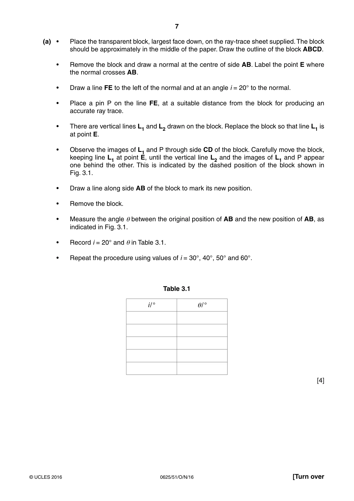
7 0625/51/O/N/16 © UCLES 2016 [Turn over (a) • Place the transparent block, largest face down, on the ray-trace sheet supplied. The block should be approximately in the middle of the paper. Draw the outline of the block ABCD. • Remove the block and draw a normal at the centre of side AB. Label the point E where the normal crosses AB. • Draw a line FE to the left of the normal and at an angle i = 20° to the normal. • Place a pin P on the line FE, at a suitable distance from the block for producing an accurate ray trace. • There are vertical lines L1 and L2 drawn on the block. Replace the block so that line L1 is at point E. • Observe the images of L1 and P through side CD of the block. Carefully move the block, keeping line L1 at point E, until the vertical line L2 and the images of L1 and P appear one behind the other. This is indicated by the dashed position of the block shown in Fig. 3.1. • Draw a line along side AB of the block to mark its new position. • Remove the block. • Measure the angle θ between the original position of AB and the new position of AB, as indicated in Fig. 3.1. • Record i = 20° and θ in Table 3.1. • Repeat the procedure using values of i = 30°, 40°, 50° and 60°. Table 3.1 i / ° θ / ° [4]
Question paper, page 8
8 0625/51/O/N/16 © UCLES 2016 BLANK PAGE
Question paper, page 9
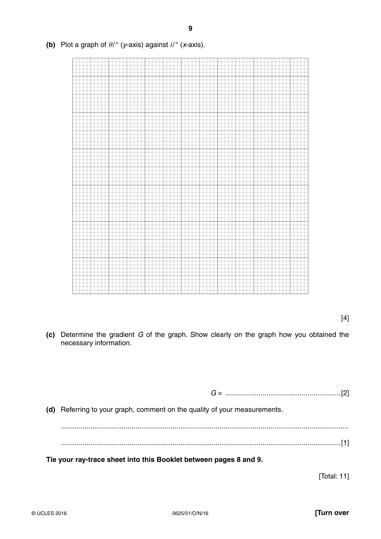
9 0625/51/O/N/16 © UCLES 2016 [Turn over (b) Plot a graph of θ / ° (y-axis) against i / ° (x-axis). [4] (c) Determine the gradient G of the graph. Show clearly on the graph how you obtained the necessary information. G = …[2] (d) Referring to your graph, comment on the quality of your measurements. … …[1] Tie your ray-trace sheet into this Booklet between pages 8 and 9. [Total: 11]
Question paper, page 10
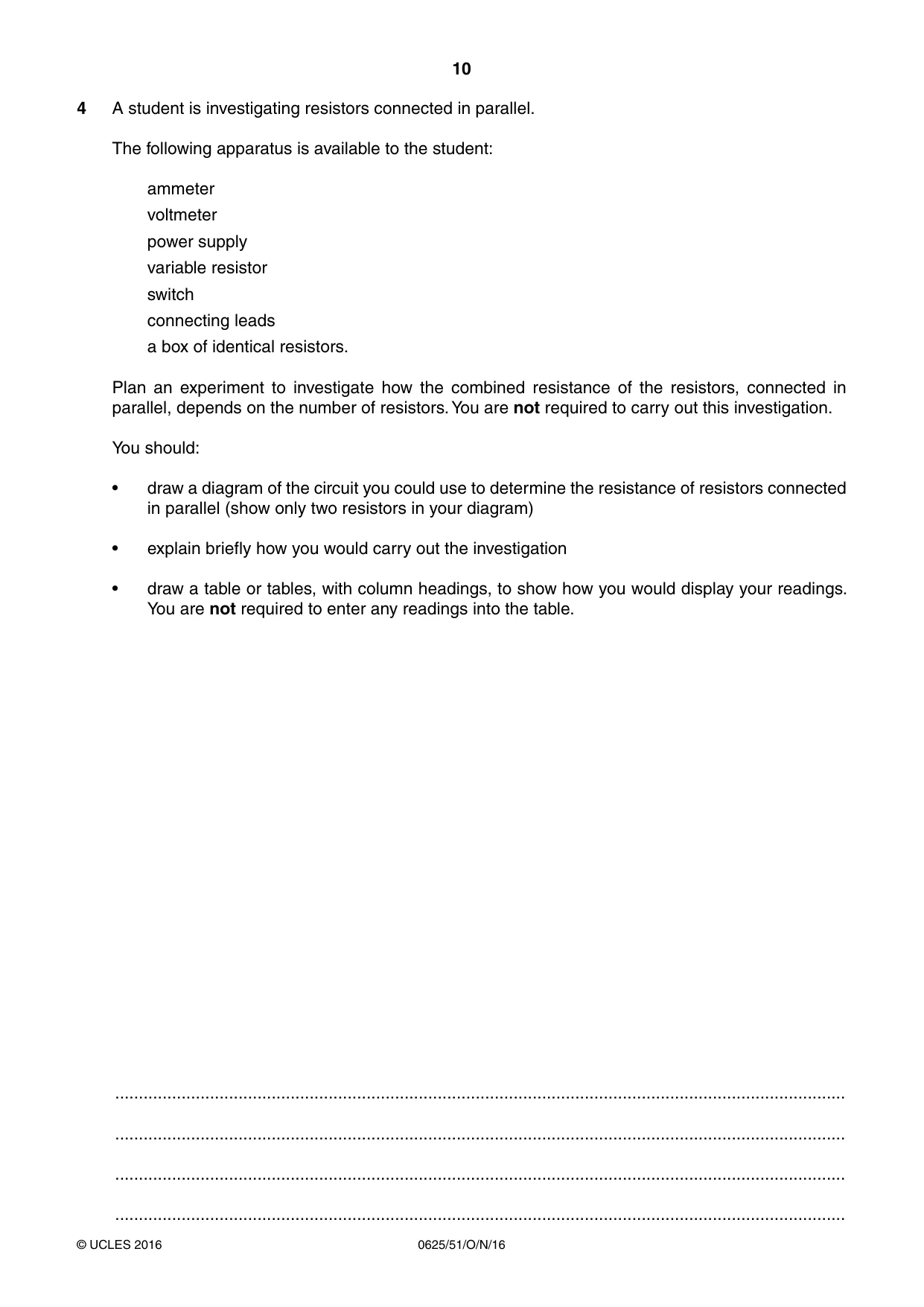
10 0625/51/O/N/16 © UCLES 2016 4 A student is investigating resistors connected in parallel. The following apparatus is available to the student: ammeter voltmeter power supply variable resistor switch connecting leads a box of identical resistors. Plan an experiment to investigate how the combined resistance of the resistors, connected in parallel, depends on the number of resistors. You are not required to carry out this investigation. You should: • draw a diagram of the circuit you could use to determine the resistance of resistors connected in parallel (show only two resistors in your diagram) • explain briefly how you would carry out the investigation • draw a table or tables, with column headings, to show how you would display your readings. You are not required to enter any readings into the table. … … … …
Question paper, page 11
11 0625/51/O/N/16 © UCLES 2016 … … … … … … … … … … … … … … … … … … … … … … … … … … [7] [Total: 7]
Question paper, page 12
12 0625/51/O/N/16 © UCLES 2016 Permission to reproduce items where third-party owned material protected by copyright is included has been sought and cleared where possible. Every reasonable effort has been made by the publisher (UCLES) to trace copyright holders, but if any items requiring clearance have unwittingly been included, the publisher will be pleased to make amends at the earliest possible opportunity. To avoid the issue of disclosure of answer-related information to candidates, all copyright acknowledgements are reproduced online in the Cambridge International Examinations Copyright Acknowledgements Booklet. This is produced for each series of examinations and is freely available to download at www.cie.org.uk after the live examination series. Cambridge International Examinations is part of the Cambridge Assessment Group. Cambridge Assessment is the brand name of University of Cambridge Local Examinations Syndicate (UCLES), which is itself a department of the University of Cambridge. BLANK PAGE
Mark scheme, page 1
® IGCSE is the registered trademark of Cambridge International Examinations. This syllabus is approved for use in England, Wales and Northern Ireland as a Cambridge International Level 1/Level 2 Certificate. This document consists of 5 printed pages. © UCLES 2016 [Turn over Cambridge International Examinations Cambridge International General Certificate of Secondary Education PHYSICS 0625/51 Paper 5 Practical October/November 2016 MARK SCHEME Maximum Mark: 40 Published This mark scheme is published as an aid to teachers and candidates, to indicate the requirements of the examination. It shows the basis on which Examiners were instructed to award marks. It does not indicate the details of the discussions that took place at an Examiners’ meeting before marking began, which would have considered the acceptability of alternative answers. Mark schemes should be read in conjunction with the question paper and the Principal Examiner Report for Teachers. Cambridge will not enter into discussions about these mark schemes. Cambridge is publishing the mark schemes for the October/November 2016 series for most Cambridge IGCSE®, Cambridge International A and AS Level components and some Cambridge O Level components.
Mark scheme, page 2
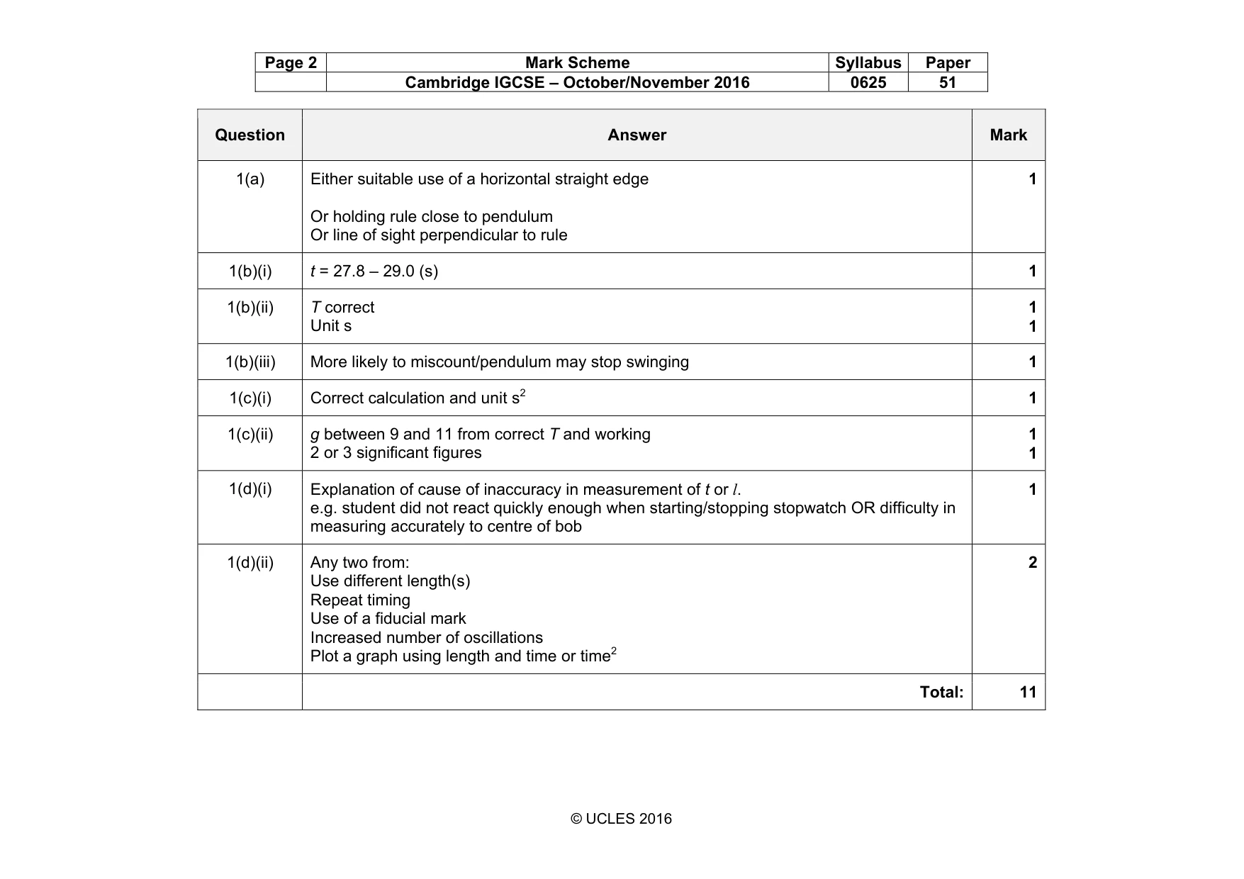
Page 2 Mark Scheme Syllabus Paper Cambridge IGCSE – October/November 2016 0625 51 © UCLES 2016 Question Answer Mark 1(a) Either suitable use of a horizontal straight edge Or holding rule close to pendulum Or line of sight perpendicular to rule 1 1(b)(i) t = 27.8 – 29.0 (s) 1 1(b)(ii) T correct Unit s 1 1 1(b)(iii) More likely to miscount/pendulum may stop swinging 1 1(c)(i) Correct calculation and unit s2 1 1(c)(ii) g between 9 and 11 from correct T and working 2 or 3 significant figures 1 1 1(d)(i) Explanation of cause of inaccuracy in measurement of t or l. e.g. student did not react quickly enough when starting/stopping stopwatch OR difficulty in measuring accurately to centre of bob 1 1(d)(ii) Any two from: Use different length(s) Repeat timing Use of a fiducial mark Increased number of oscillations Plot a graph using length and time or time2 2 Total: 11
Mark scheme, page 3
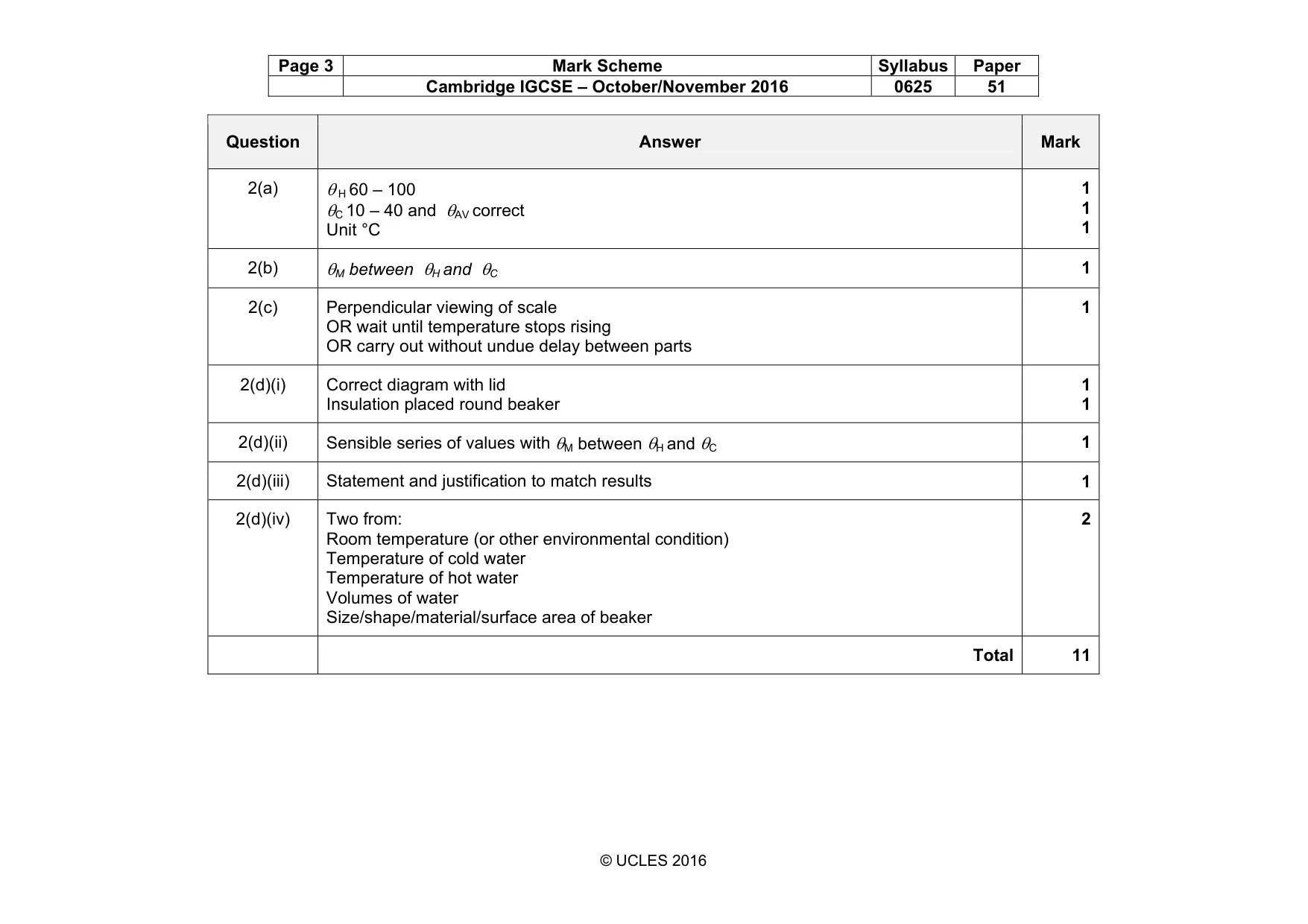
Page 3 Mark Scheme Syllabus Paper Cambridge IGCSE – October/November 2016 0625 51 © UCLES 2016 Question Answer Mark 2(a) θ H 60 – 100 θC 10 – 40 and θAV correct Unit °C 1 1 1 2(b) θM between θH and θC 1 2(c) Perpendicular viewing of scale OR wait until temperature stops rising OR carry out without undue delay between parts 1 2(d)(i) Correct diagram with lid Insulation placed round beaker 1 1 2(d)(ii) Sensible series of values with θM between θH and θC 1 2(d)(iii) Statement and justification to match results 1 2(d)(iv) Two from: Room temperature (or other environmental condition) Temperature of cold water Temperature of hot water Volumes of water Size/shape/material/surface area of beaker 2 Total 11
Mark scheme, page 4
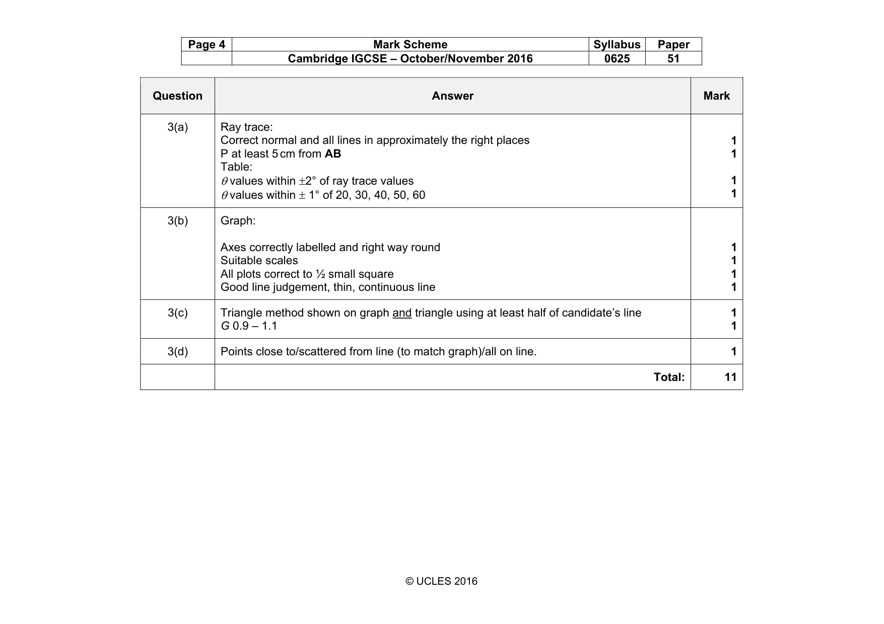
Page 4 Mark Scheme Syllabus Paper Cambridge IGCSE – October/November 2016 0625 51 © UCLES 2016 Question Answer Mark 3(a) Ray trace: Correct normal and all lines in approximately the right places P at least 5 cm from AB Table: θ values within ±2° of ray trace values θ values within ± 1° of 20, 30, 40, 50, 60 1 1 1 1 3(b) Graph: Axes correctly labelled and right way round Suitable scales All plots correct to ½ small square Good line judgement, thin, continuous line 1 1 1 1 3(c) Triangle method shown on graph and triangle using at least half of candidate’s line G 0.9 – 1.1 1 1 3(d) Points close to/scattered from line (to match graph)/all on line. 1 Total: 11
Mark scheme, page 5
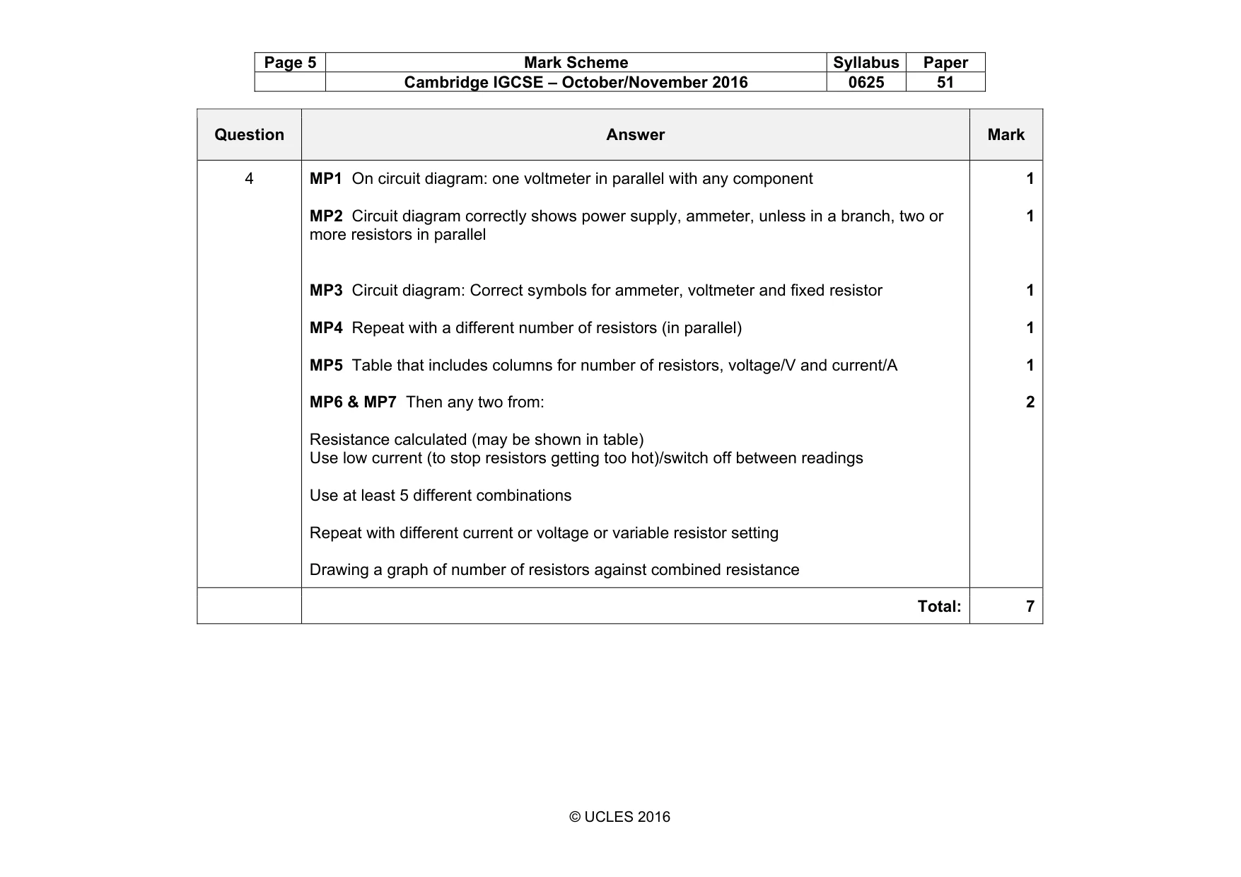
Page 5 Mark Scheme Syllabus Paper Cambridge IGCSE – October/November 2016 0625 51 © UCLES 2016 Question Answer Mark 4 MP1 On circuit diagram: one voltmeter in parallel with any component MP2 Circuit diagram correctly shows power supply, ammeter, unless in a branch, two or more resistors in parallel MP3 Circuit diagram: Correct symbols for ammeter, voltmeter and fixed resistor MP4 Repeat with a different number of resistors (in parallel) MP5 Table that includes columns for number of resistors, voltage/V and current/A MP6 & MP7 Then any two from: Resistance calculated (may be shown in table) Use low current (to stop resistors getting too hot)/switch off between readings Use at least 5 different combinations Repeat with different current or voltage or variable resistor setting Drawing a graph of number of resistors against combined resistance 1 1 1 1 1 2 Total: 7
What you needed in this session
Cambridge’s own grade thresholds for 2016 Oct/Nov, Paper 5 · Variant 1. A higher threshold means an easier paper — the bar moves with how the cohort did.