Cambridge IGCSE Design and Technology 0445 — 2011 Oct/Nov Paper 3 · Variant 1
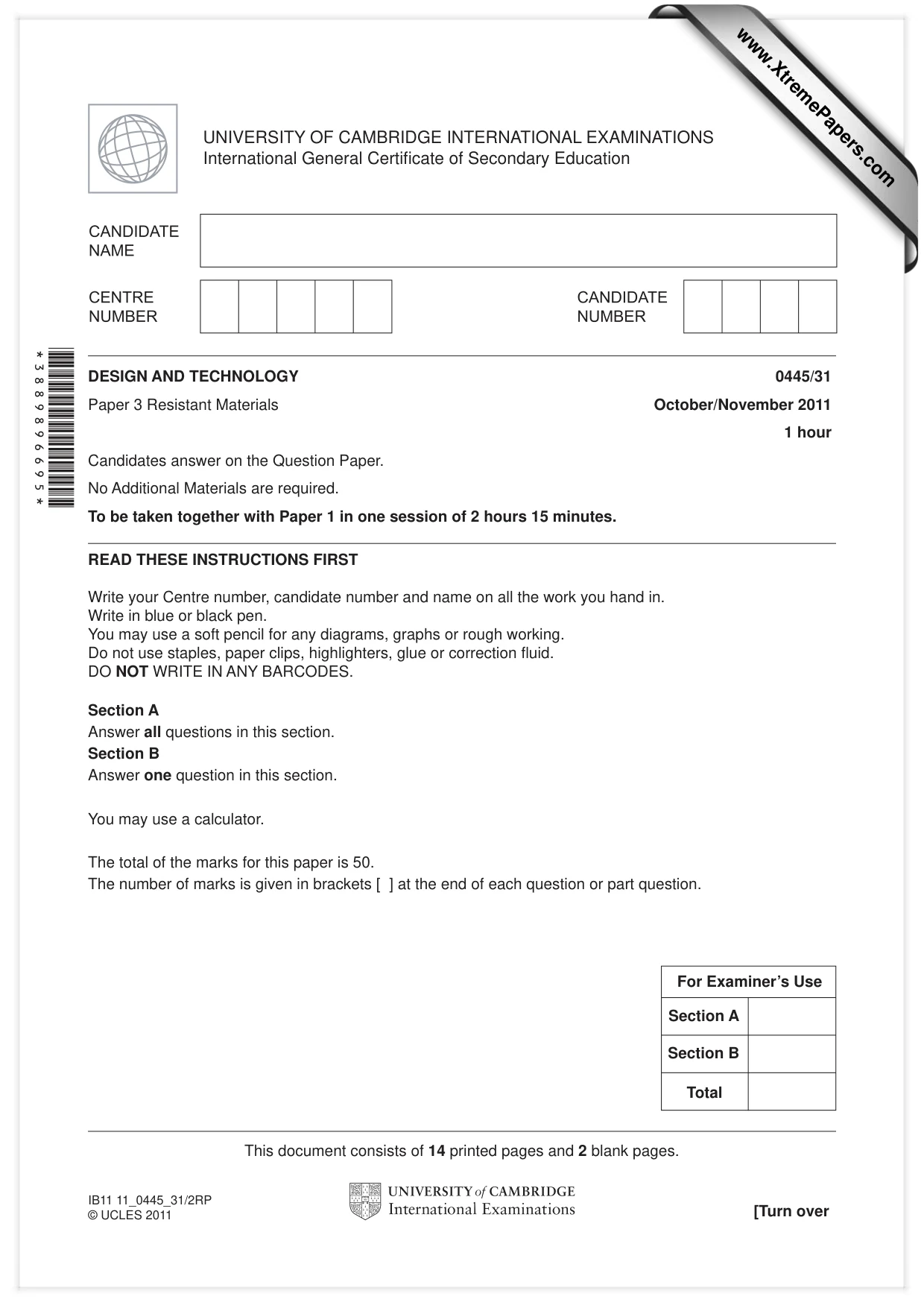
0445/31/O/N/11
The question paper and its mark scheme, free to read here and free to download. This is Cambridge’s own paper, exactly as it was sat.
Question paper16 pages

Mark scheme5 pages
Answers below. Sit the paper first if you are practising.
Paper as text
Question paper, page 1
READ THESE INSTRUCTIONS FIRST Write your Centre number, candidate number and name on all the work you hand in. Write in blue or black pen. You may use a soft pencil for any diagrams, graphs or rough working. Do not use staples, paper clips, highlighters, glue or correction fl uid. DO NOT WRITE IN ANY BARCODES. Section A Answer all questions in this section. Section B Answer one question in this section. You may use a calculator. The total of the marks for this paper is 50. The number of marks is given in brackets [ ] at the end of each question or part question. DESIGN AND TECHNOLOGY 0445/31 Paper 3 Resistant Materials October/November 2011 1 hour Candidates answer on the Question Paper. No Additional Materials are required. To be taken together with Paper 1 in one session of 2 hours 15 minutes. UNIVERSITY OF CAMBRIDGE INTERNATIONAL EXAMINATIONS International General Certifi cate of Secondary Education This document consists of 14 printed pages and 2 blank pages. [Turn over IB11 11_0445_31/2RP © UCLES 2011 *3889896695* For Examiner’s Use Total Section A Section B www.XtremePapers.com
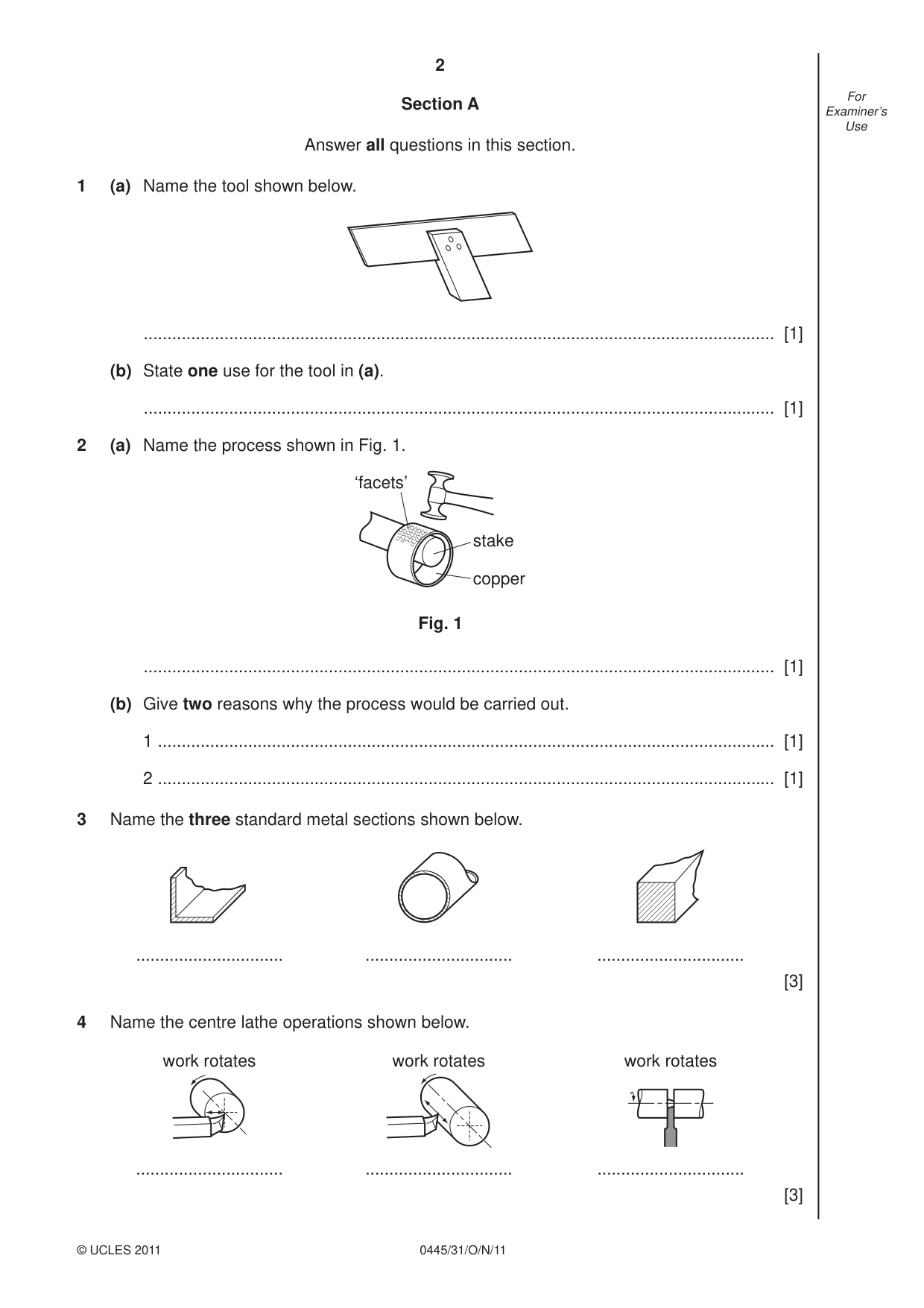
Question paper, page 2
2 0445/31/O/N/11 © UCLES 2011 For Examiner’s Use Section A Answer all questions in this section. 1 (a) Name the tool shown below. … [1] (b) State one use for the tool in (a). … [1] 2 (a) Name the process shown in Fig. 1. ‘facets’ stake copper Fig. 1 … [1] (b) Give two reasons why the process would be carried out. 1 … [1] 2 … [1] 3 Name the three standard metal sections shown below. … … … [3] 4 Name the centre lathe operations shown below. … work rotates … … work rotates work rotates [3]
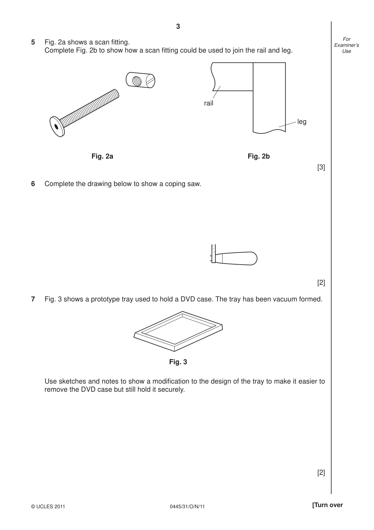
Question paper, page 3
3 0445/31/O/N/11 © UCLES 2011 [Turn over For Examiner’s Use 5 Fig. 2a shows a scan fi tting. Complete Fig. 2b to show how a scan fi tting could be used to join the rail and leg. Fig. 2a Fig. 2b leg rail [3] 6 Complete the drawing below to show a coping saw. [2] 7 Fig. 3 shows a prototype tray used to hold a DVD case. The tray has been vacuum formed. Fig. 3 Use sketches and notes to show a modifi cation to the design of the tray to make it easier to remove the DVD case but still hold it securely. [2]
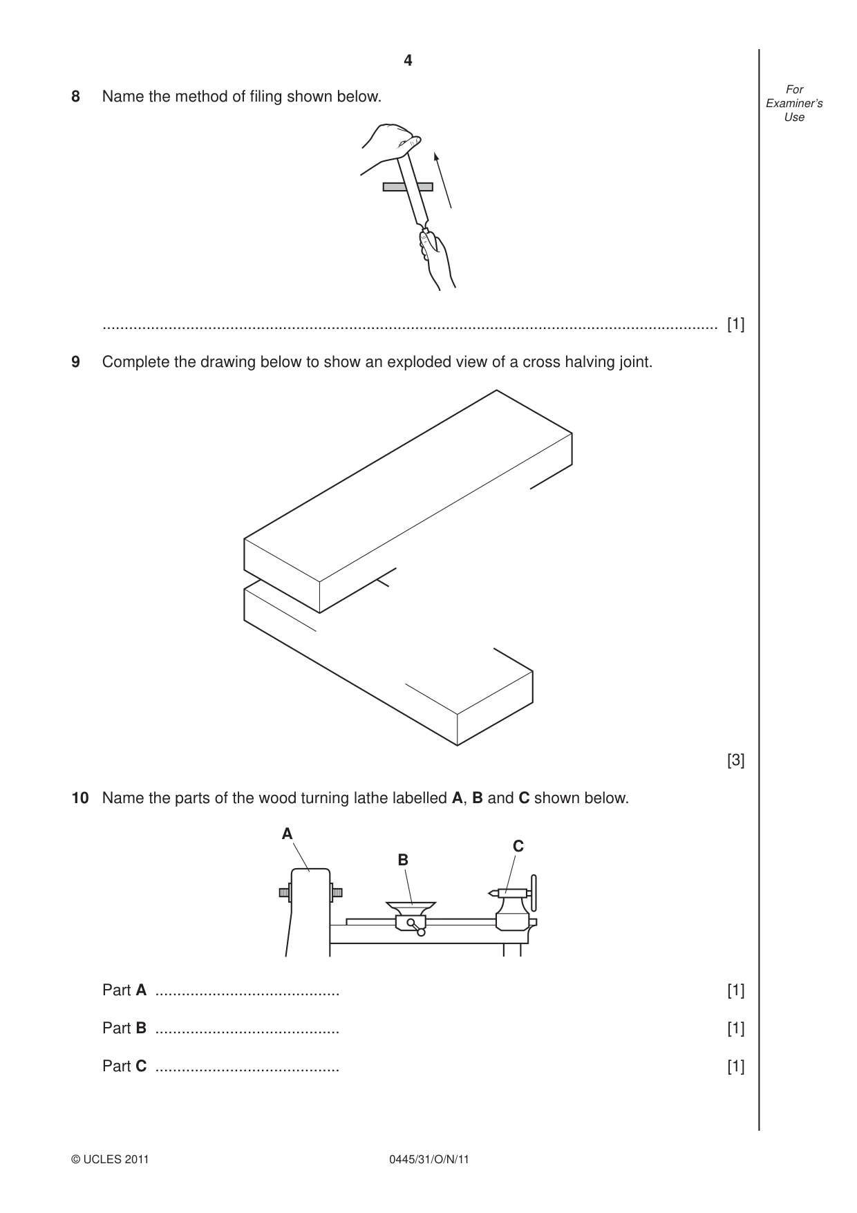
Question paper, page 4
4 0445/31/O/N/11 © UCLES 2011 For Examiner’s Use 8 Name the method of fi ling shown below. … [1] 9 Complete the drawing below to show an exploded view of a cross halving joint. [3] 10 Name the parts of the wood turning lathe labelled A, B and C shown below. A B C Part A … [1] Part B … [1] Part C … [1]
Question paper, page 5
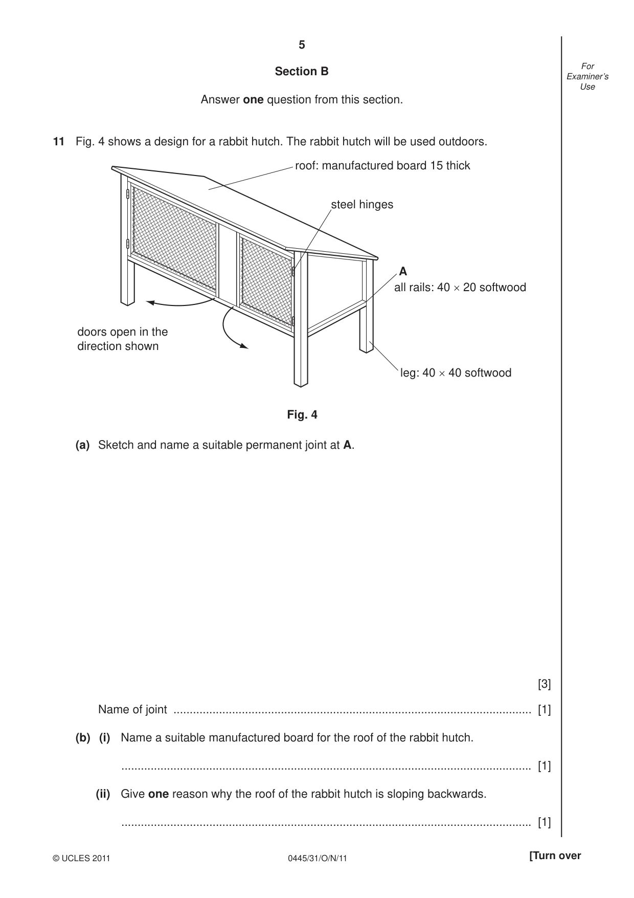
5 0445/31/O/N/11 © UCLES 2011 [Turn over For Examiner’s Use Section B Answer one question from this section. 11 Fig. 4 shows a design for a rabbit hutch. The rabbit hutch will be used outdoors. roof: manufactured board 15 thick steel hinges A all rails: 40 × 20 softwood leg: 40 × 40 softwood doors open in the direction shown Fig. 4 (a) Sketch and name a suitable permanent joint at A. [3] Name of joint … [1] (b) (i) Name a suitable manufactured board for the roof of the rabbit hutch. … [1] (ii) Give one reason why the roof of the rabbit hutch is sloping backwards. … [1]
Question paper, page 6
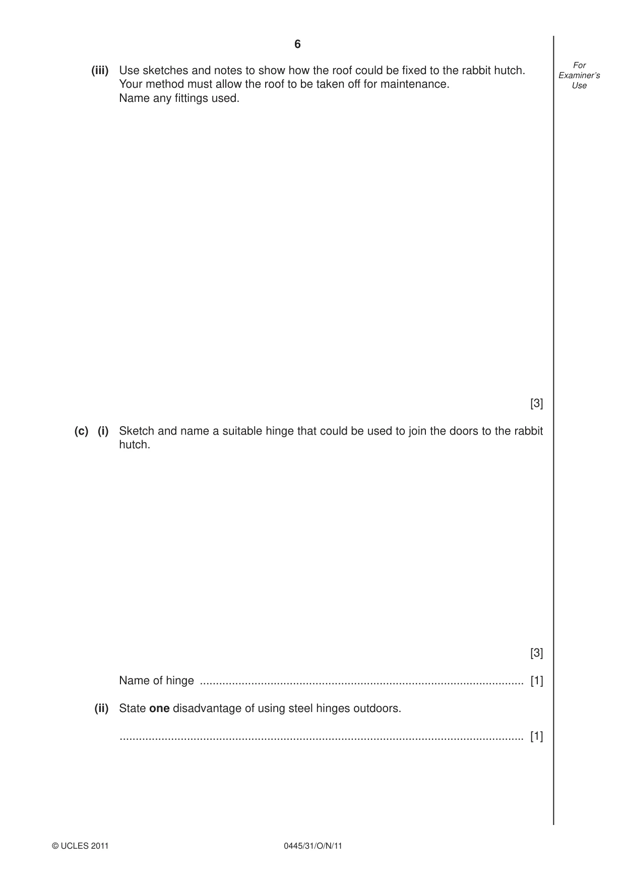
6 0445/31/O/N/11 © UCLES 2011 For Examiner’s Use (iii) Use sketches and notes to show how the roof could be fi xed to the rabbit hutch. Your method must allow the roof to be taken off for maintenance. Name any fi ttings used. [3] (c) (i) Sketch and name a suitable hinge that could be used to join the doors to the rabbit hutch. [3] Name of hinge … [1] (ii) State one disadvantage of using steel hinges outdoors. … [1]
Question paper, page 7
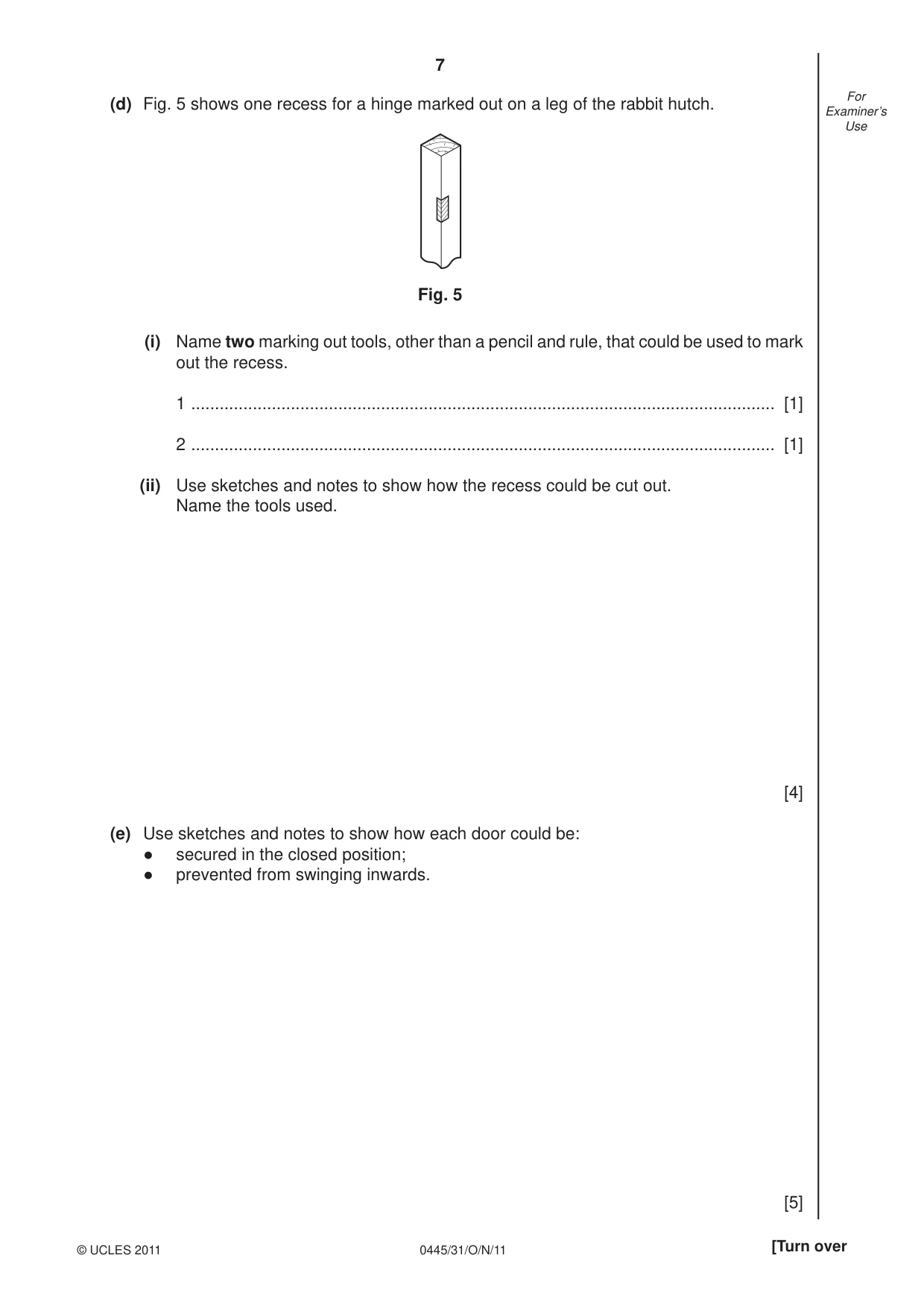
7 0445/31/O/N/11 © UCLES 2011 [Turn over For Examiner’s Use (d) Fig. 5 shows one recess for a hinge marked out on a leg of the rabbit hutch. Fig. 5 (i) Name two marking out tools, other than a pencil and rule, that could be used to mark out the recess. 1 … [1] 2 … [1] (ii) Use sketches and notes to show how the recess could be cut out. Name the tools used. [4] (e) Use sketches and notes to show how each door could be: ● secured in the closed position; ● prevented from swinging inwards. [5]
Question paper, page 8
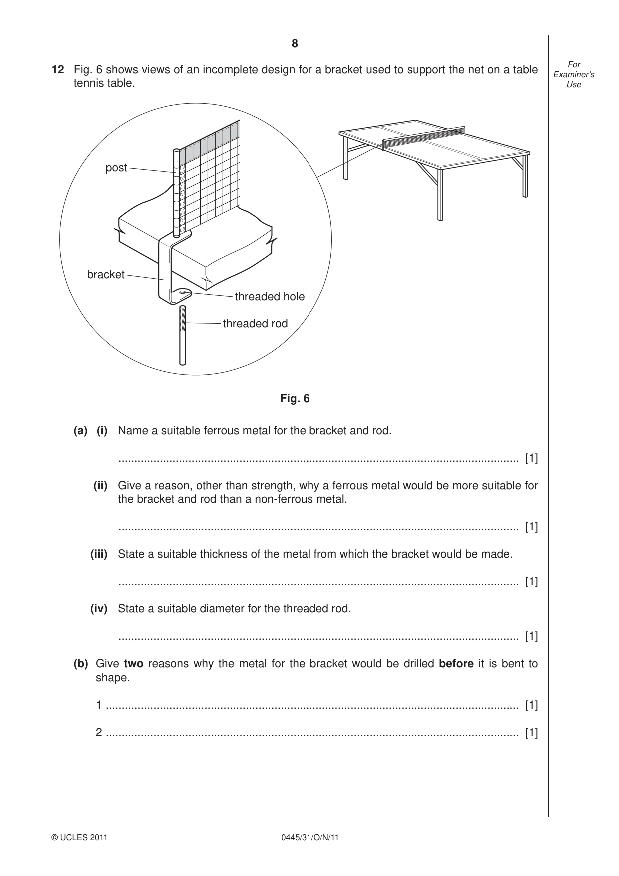
8 0445/31/O/N/11 © UCLES 2011 For Examiner’s Use 12 Fig. 6 shows views of an incomplete design for a bracket used to support the net on a table tennis table. post bracket threaded hole threaded rod Fig. 6 (a) (i) Name a suitable ferrous metal for the bracket and rod. … [1] (ii) Give a reason, other than strength, why a ferrous metal would be more suitable for the bracket and rod than a non-ferrous metal. … [1] (iii) State a suitable thickness of the metal from which the bracket would be made. … [1] (iv) State a suitable diameter for the threaded rod. … [1] (b) Give two reasons why the metal for the bracket would be drilled before it is bent to shape. 1 … [1] 2 … [1]
Question paper, page 9
9 0445/31/O/N/11 © UCLES 2011 [Turn over For Examiner’s Use (c) Use sketches and notes to show how: (i) a thread could be cut in the hole in the bracket; [4] (ii) a thread could be cut on the rod. [4] (d) In use, the end of the threaded rod damages the underside of the table. Use sketches and notes to show how this could be prevented. [2]
Question paper, page 10
10 0445/31/O/N/11 © UCLES 2011 For Examiner’s Use (e) In use, the threaded rod is diffi cult to tighten by hand. Use sketches and notes to show how the threaded rod could be modifi ed to make it easier to tighten. [3] (f) Use sketches and notes to show how the post could be brazed into the bracket. Include details of all the equipment used in the brazing process. [6]
Question paper, page 11
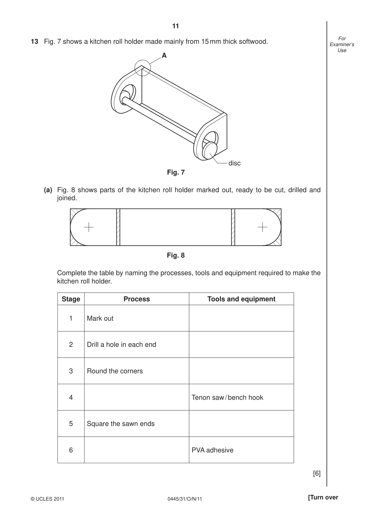
11 0445/31/O/N/11 © UCLES 2011 [Turn over For Examiner’s Use 13 Fig. 7 shows a kitchen roll holder made mainly from 15 mm thick softwood. A disc Fig. 7 (a) Fig. 8 shows parts of the kitchen roll holder marked out, ready to be cut, drilled and joined. Fig. 8 Complete the table by naming the processes, tools and equipment required to make the kitchen roll holder. Stage Process Tools and equipment 1 Mark out 2 Drill a hole in each end 3 Round the corners 4 Tenon saw / bench hook 5 Square the sawn ends 6 PVA adhesive [6]
Question paper, page 12
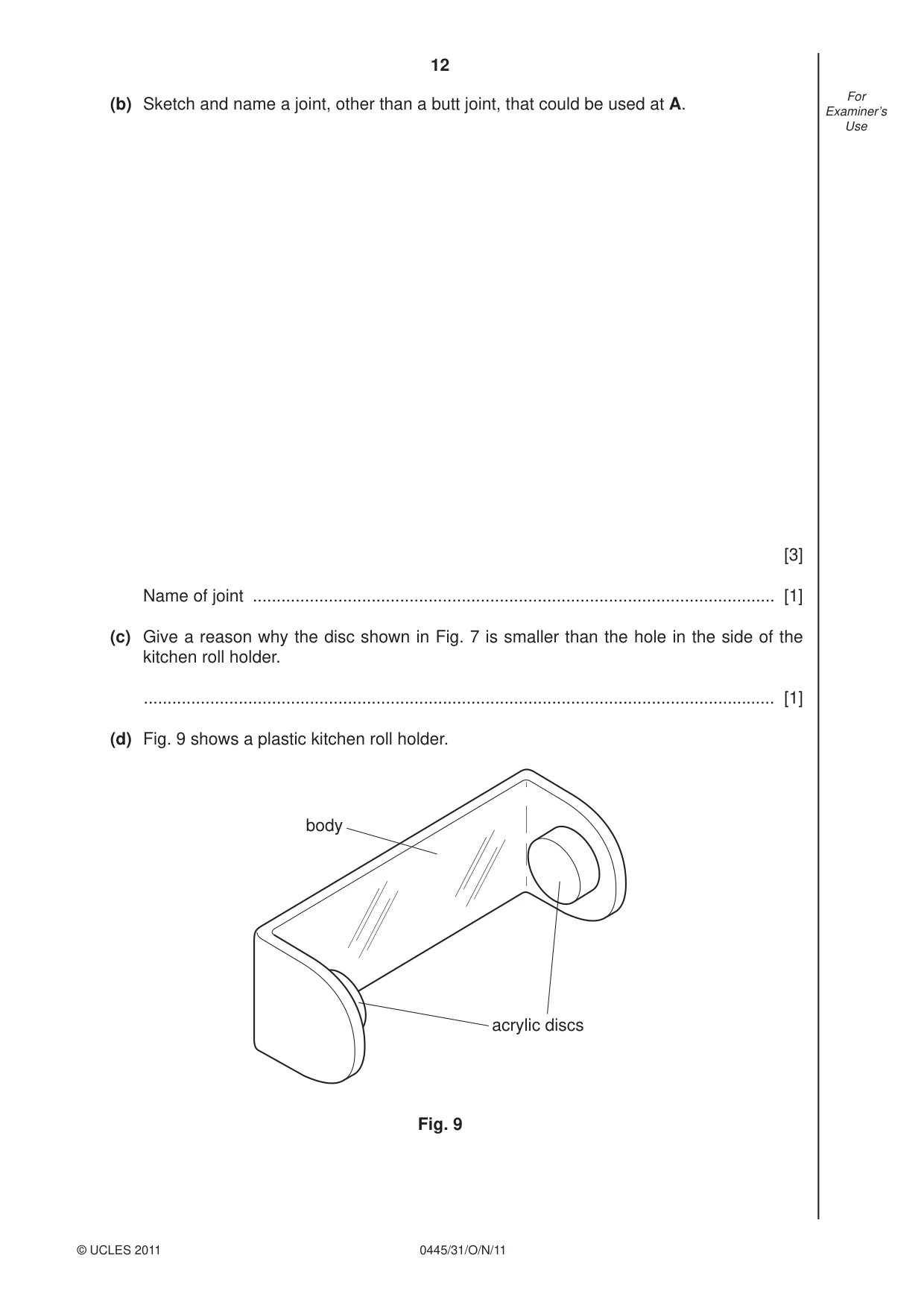
12 0445/31/O/N/11 © UCLES 2011 For Examiner’s Use (b) Sketch and name a joint, other than a butt joint, that could be used at A. [3] Name of joint … [1] (c) Give a reason why the disc shown in Fig. 7 is smaller than the hole in the side of the kitchen roll holder. … [1] (d) Fig. 9 shows a plastic kitchen roll holder. body acrylic discs Fig. 9
Question paper, page 13
13 0445/31/O/N/11 © UCLES 2011 [Turn over For Examiner’s Use (i) Use sketches and notes to show how the body of the kitchen roll holder could be bent to shape from a single piece of acrylic. [4] (ii) Use sketches and notes to show how the acrylic discs to support the kitchen roll could be made and joined to the body of the kitchen roll holder using acrylic cement. [4]
Question paper, page 14
14 0445/31/O/N/11 © UCLES 2011 For Examiner’s Use (iii) State two safety precautions to be taken when using acrylic cement. 1 … [1] 2 … [1] (e) Explain how the fl exible property of acrylic has been used in the design of the plastic kitchen roll holder. … … … [2] (f) The kitchen roll holder in Fig. 9 could also be made by injection moulding. Explain why injection moulding is only suitable when making products in large quantities. … … … [2]
Question paper, page 15
15 0445/31/O/N/11 © UCLES 2011 BLANK PAGE
Question paper, page 16
16 0445/31/O/N/11 Permission to reproduce items where third-party owned material protected by copyright is included has been sought and cleared where possible. Every reasonable effort has been made by the publisher (UCLES) to trace copyright holders, but if any items requiring clearance have unwittingly been included the publisher will be pleased to make amends at the earliest possible opportunity. University of Cambridge International Examinations is part of the Cambridge Assessment Group. Cambridge Assessment is the brand name of University of Cambridge Local Examinations Syndicate (UCLES), which is itself a department of the University of Cambridge. BLANK PAGE © UCLES 2011
Mark scheme, page 1
UNIVERSITY OF CAMBRIDGE INTERNATIONAL EXAMINATIONS International General Certificate of Secondary Education MARK SCHEME for the October/November 2011 question paper for the guidance of teachers 0445 DESIGN AND TECHNOLOGY 0445/31 Paper 3 (Resistant Materials), maximum raw mark 50 This mark scheme is published as an aid to teachers and candidates, to indicate the requirements of the examination. It shows the basis on which Examiners were instructed to award marks. It does not indicate the details of the discussions that took place at an Examiners’ meeting before marking began, which would have considered the acceptability of alternative answers. Mark schemes must be read in conjunction with the question papers and the report on the examination. • Cambridge will not enter into discussions or correspondence in connection with these mark schemes. Cambridge is publishing the mark schemes for the October/November 2011 question papers for most IGCSE, GCE Advanced Level and Advanced Subsidiary Level syllabuses and some Ordinary Level syllabuses. www.XtremePapers.com
Mark scheme, page 2
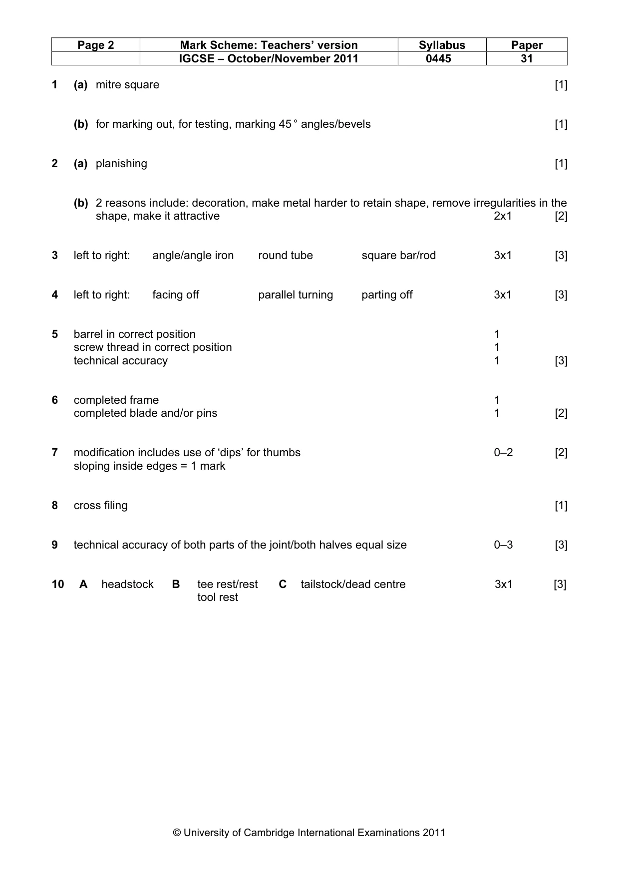
Page 2 Mark Scheme: Teachers’ version Syllabus Paper IGCSE – October/November 2011 0445 31 © University of Cambridge International Examinations 2011 1 (a) mitre square [1] (b) for marking out, for testing, marking 45 ° angles/bevels [1] 2 (a) planishing [1] (b) 2 reasons include: decoration, make metal harder to retain shape, remove irregularities in the shape, make it attractive 2x1 [2] 3 left to right: angle/angle iron round tube square bar/rod 3x1 [3] 4 left to right: facing off parallel turning parting off 3x1 [3] 5 barrel in correct position 1 screw thread in correct position 1 technical accuracy 1 [3] 6 completed frame 1 completed blade and/or pins 1 [2] 7 modification includes use of ‘dips’ for thumbs 0–2 [2] sloping inside edges = 1 mark 8 cross filing [1] 9 technical accuracy of both parts of the joint/both halves equal size 0–3 [3] 10 A headstock B tee rest/rest C tailstock/dead centre 3x1 [3] tool rest
Mark scheme, page 3
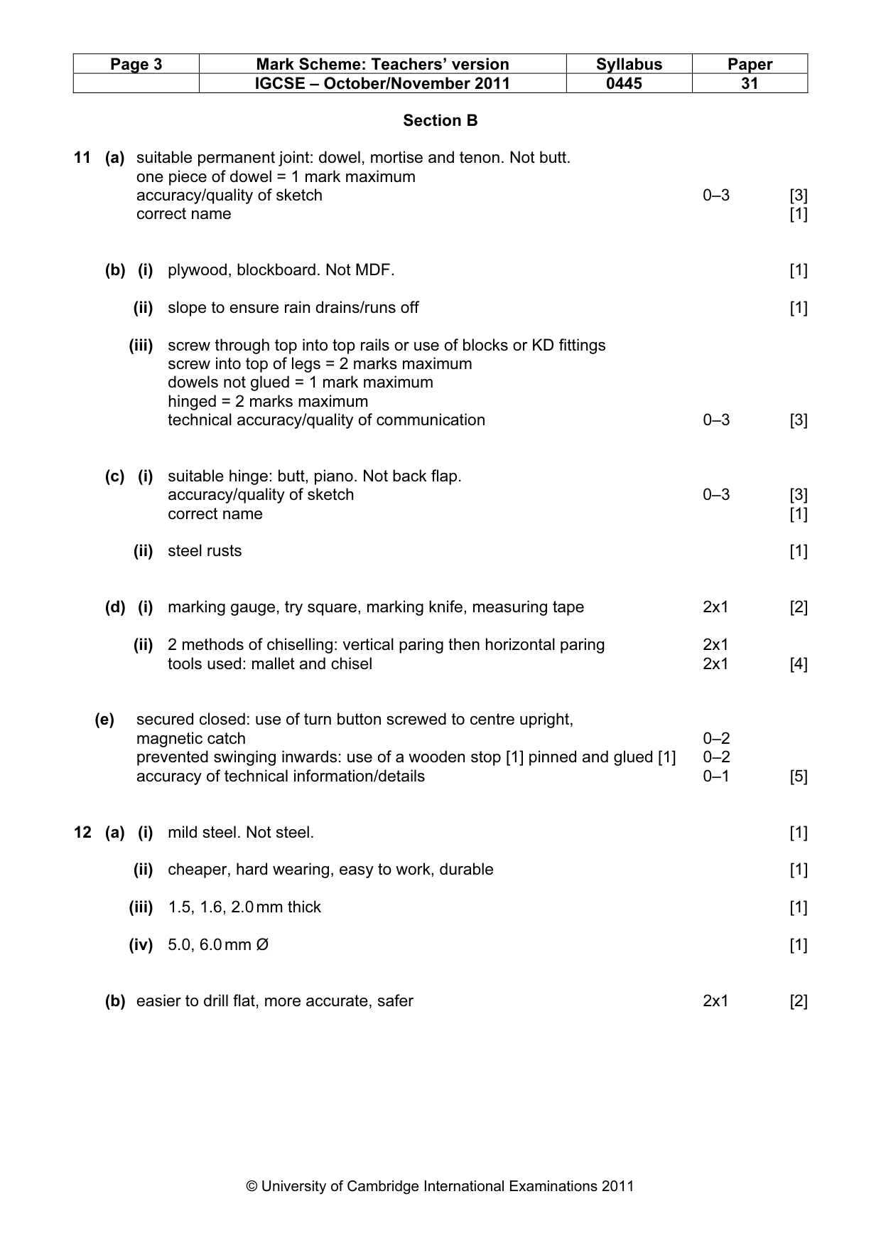
Page 3 Mark Scheme: Teachers’ version Syllabus Paper IGCSE – October/November 2011 0445 31 © University of Cambridge International Examinations 2011 Section B 11 (a) suitable permanent joint: dowel, mortise and tenon. Not butt. one piece of dowel = 1 mark maximum accuracy/quality of sketch 0–3 [3] correct name [1] (b) (i) plywood, blockboard. Not MDF. [1] (ii) slope to ensure rain drains/runs off [1] (iii) screw through top into top rails or use of blocks or KD fittings screw into top of legs = 2 marks maximum dowels not glued = 1 mark maximum hinged = 2 marks maximum technical accuracy/quality of communication 0–3 [3] (c) (i) suitable hinge: butt, piano. Not back flap. accuracy/quality of sketch 0–3 [3] correct name [1] (ii) steel rusts [1] (d) (i) marking gauge, try square, marking knife, measuring tape 2x1 [2] (ii) 2 methods of chiselling: vertical paring then horizontal paring 2x1 tools used: mallet and chisel 2x1 [4] (e) secured closed: use of turn button screwed to centre upright, magnetic catch 0–2 prevented swinging inwards: use of a wooden stop [1] pinned and glued [1] 0–2 accuracy of technical information/details 0–1 [5] 12 (a) (i) mild steel. Not steel. [1] (ii) cheaper, hard wearing, easy to work, durable [1] (iii) 1.5, 1.6, 2.0 mm thick [1] (iv) 5.0, 6.0 mm Ø [1] (b) easier to drill flat, more accurate, safer 2x1 [2]
Mark scheme, page 4
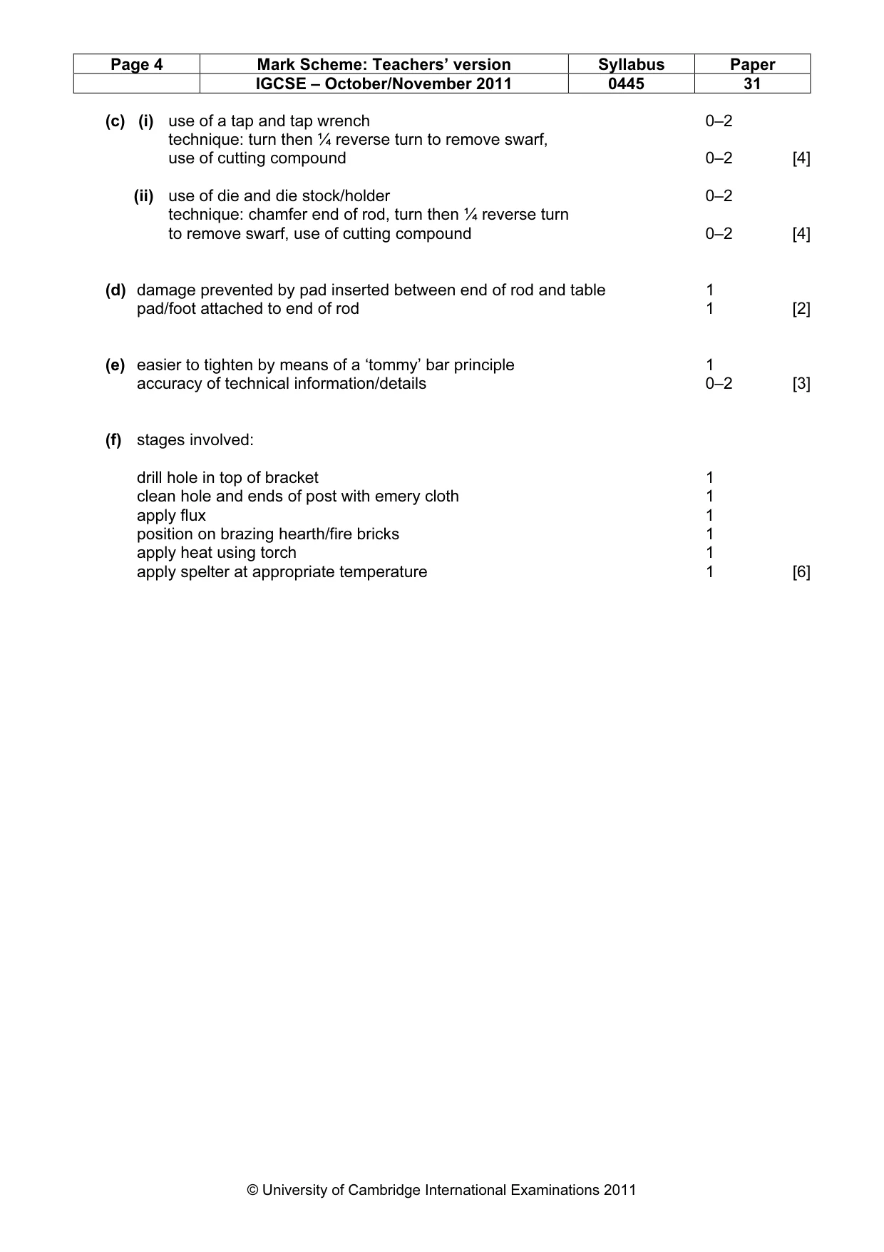
Page 4 Mark Scheme: Teachers’ version Syllabus Paper IGCSE – October/November 2011 0445 31 © University of Cambridge International Examinations 2011 (c) (i) use of a tap and tap wrench 0–2 technique: turn then ¼ reverse turn to remove swarf, use of cutting compound 0–2 [4] (ii) use of die and die stock/holder 0–2 technique: chamfer end of rod, turn then ¼ reverse turn to remove swarf, use of cutting compound 0–2 [4] (d) damage prevented by pad inserted between end of rod and table 1 pad/foot attached to end of rod 1 [2] (e) easier to tighten by means of a ‘tommy’ bar principle 1 accuracy of technical information/details 0–2 [3] (f) stages involved: drill hole in top of bracket 1 clean hole and ends of post with emery cloth 1 apply flux 1 position on brazing hearth/fire bricks 1 apply heat using torch 1 apply spelter at appropriate temperature 1 [6]
Mark scheme, page 5
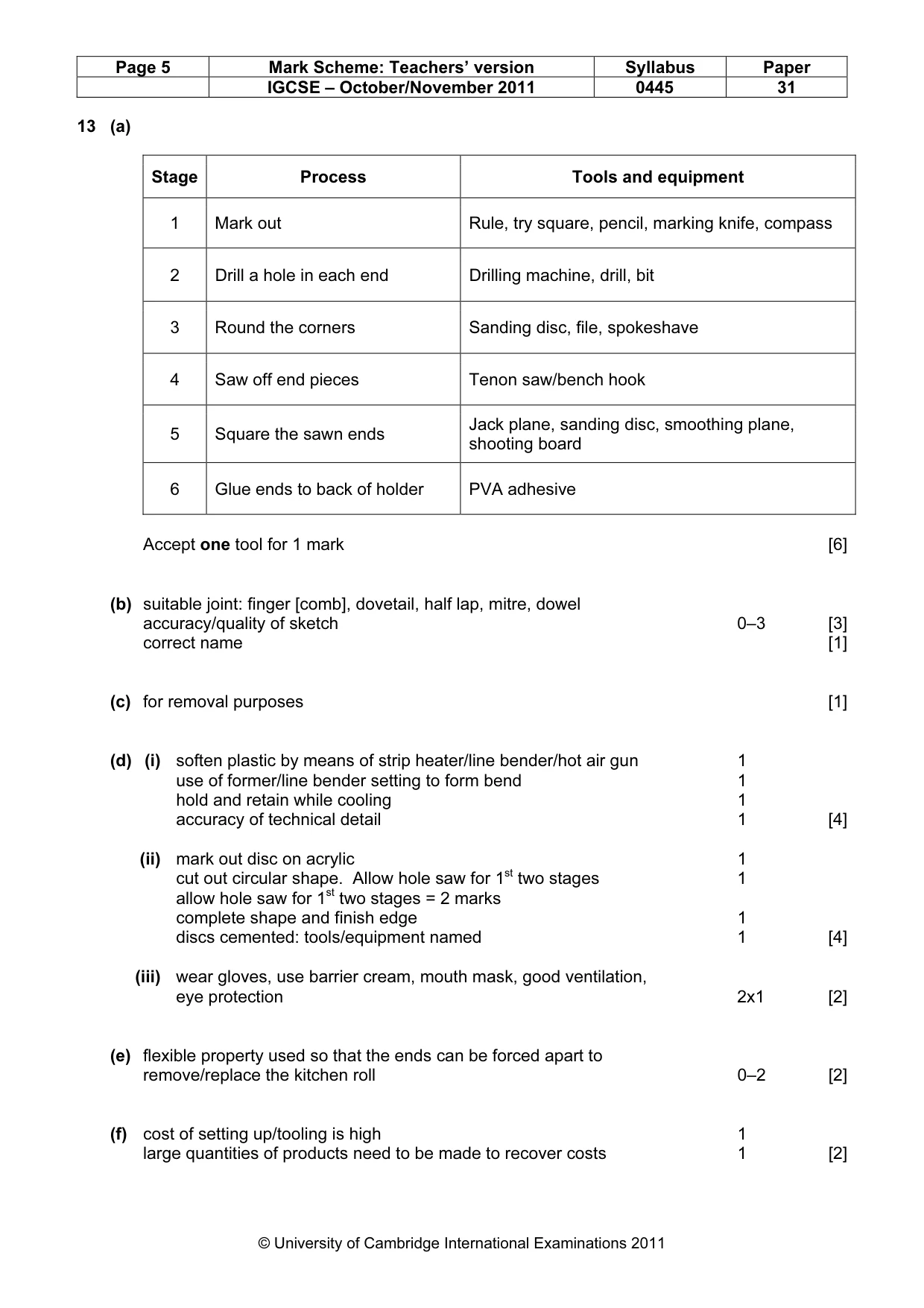
Page 5 Mark Scheme: Teachers’ version Syllabus Paper IGCSE – October/November 2011 0445 31 © University of Cambridge International Examinations 2011 13 (a) Stage Process Tools and equipment 1 Mark out Rule, try square, pencil, marking knife, compass 2 Drill a hole in each end Drilling machine, drill, bit 3 Round the corners Sanding disc, file, spokeshave 4 Saw off end pieces Tenon saw/bench hook 5 Square the sawn ends Jack plane, sanding disc, smoothing plane, shooting board 6 Glue ends to back of holder PVA adhesive Accept one tool for 1 mark [6] (b) suitable joint: finger [comb], dovetail, half lap, mitre, dowel accuracy/quality of sketch 0–3 [3] correct name [1] (c) for removal purposes [1] (d) (i) soften plastic by means of strip heater/line bender/hot air gun 1 use of former/line bender setting to form bend 1 hold and retain while cooling 1 accuracy of technical detail 1 [4] (ii) mark out disc on acrylic 1 cut out circular shape. Allow hole saw for 1st two stages 1 allow hole saw for 1st two stages = 2 marks complete shape and finish edge 1 discs cemented: tools/equipment named 1 [4] (iii) wear gloves, use barrier cream, mouth mask, good ventilation, eye protection 2x1 [2] (e) flexible property used so that the ends can be forced apart to remove/replace the kitchen roll 0–2 [2] (f) cost of setting up/tooling is high 1 large quantities of products need to be made to recover costs 1 [2]