Cambridge IGCSE Design and Technology 0445 — 2011 Oct/Nov Paper 3 · Variant 3
0445/33/O/N/11
The question paper and its mark scheme, free to read here and free to download. This is Cambridge’s own paper, exactly as it was sat.
Question paper16 pages
Mark scheme7 pages
Answers below. Sit the paper first if you are practising.
Paper as text
Question paper, page 1
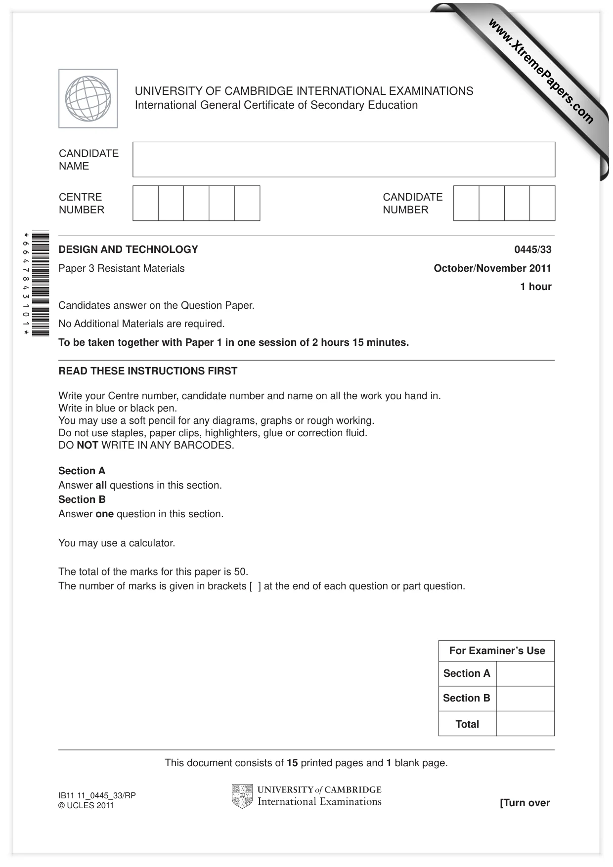
READ THESE INSTRUCTIONS FIRST Write your Centre number, candidate number and name on all the work you hand in. Write in blue or black pen. You may use a soft pencil for any diagrams, graphs or rough working. Do not use staples, paper clips, highlighters, glue or correction fl uid. DO NOT WRITE IN ANY BARCODES. Section A Answer all questions in this section. Section B Answer one question in this section. You may use a calculator. The total of the marks for this paper is 50. The number of marks is given in brackets [ ] at the end of each question or part question. DESIGN AND TECHNOLOGY 0445/33 Paper 3 Resistant Materials October/November 2011 1 hour Candidates answer on the Question Paper. No Additional Materials are required. To be taken together with Paper 1 in one session of 2 hours 15 minutes. UNIVERSITY OF CAMBRIDGE INTERNATIONAL EXAMINATIONS International General Certifi cate of Secondary Education This document consists of 15 printed pages and 1 blank page. [Turn over IB11 11_0445_33/RP © UCLES 2011 *6647843101* For Examiner’s Use Total Section A Section B www.XtremePapers.com
Question paper, page 2
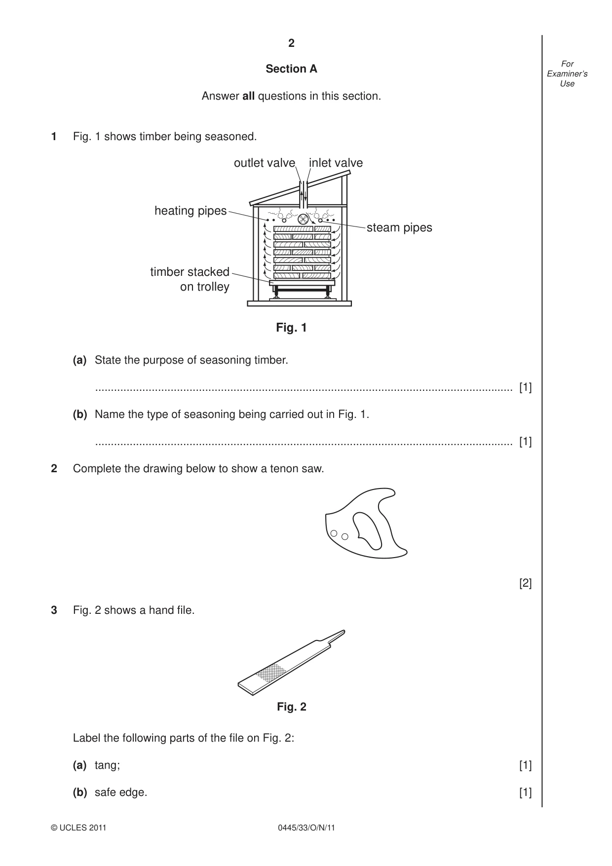
2 0445/33/O/N/11 © UCLES 2011 For Examiner’s Use Section A Answer all questions in this section. 1 Fig. 1 shows timber being seasoned. heating pipes steam pipes outlet valve inlet valve timber stacked on trolley Fig. 1 (a) State the purpose of seasoning timber. … [1] (b) Name the type of seasoning being carried out in Fig. 1. … [1] 2 Complete the drawing below to show a tenon saw. [2] 3 Fig. 2 shows a hand fi le. Fig. 2 Label the following parts of the fi le on Fig. 2: (a) tang; [1] (b) safe edge. [1]
Question paper, page 3
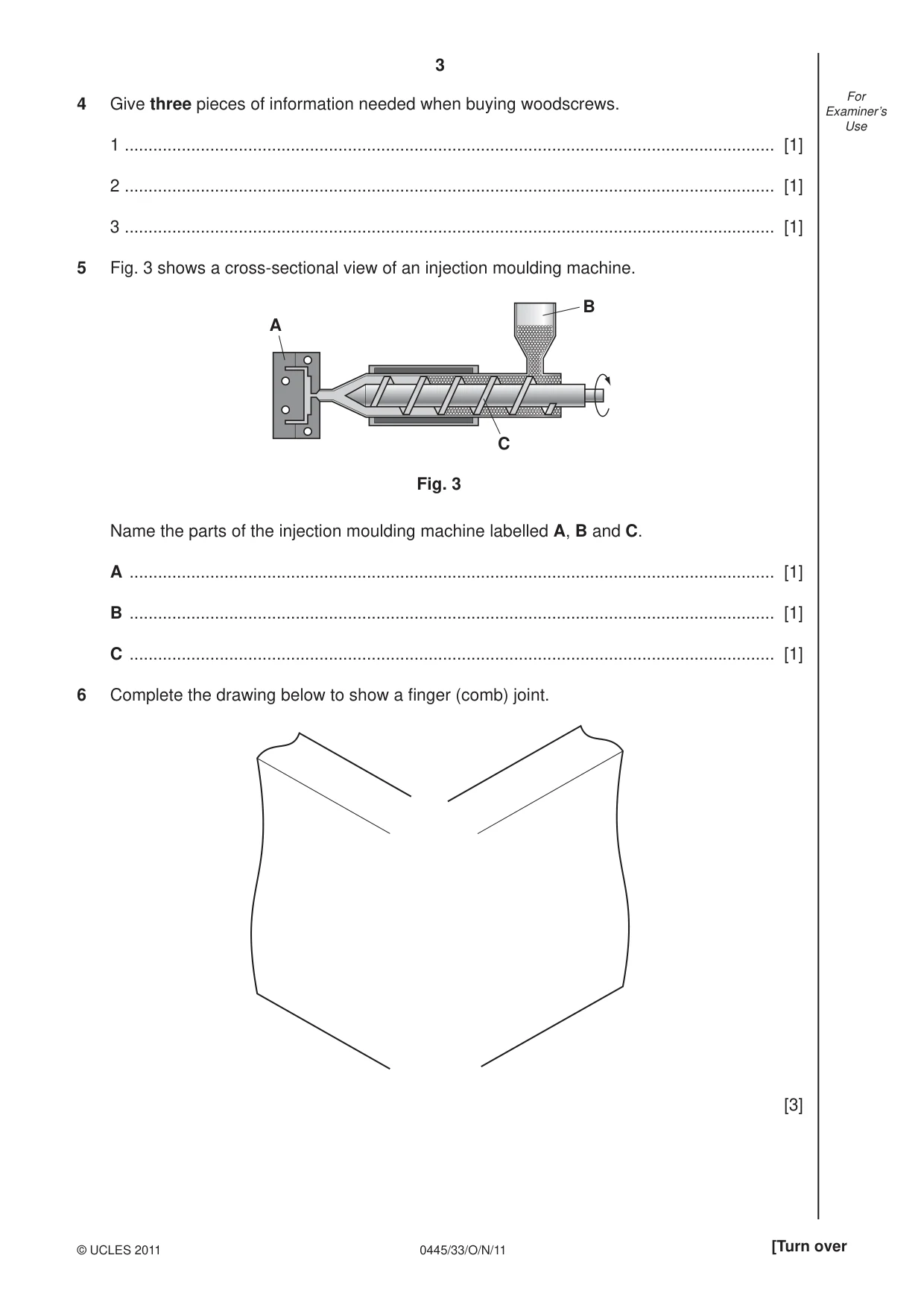
3 0445/33/O/N/11 © UCLES 2011 [Turn over For Examiner’s Use 4 Give three pieces of information needed when buying woodscrews. 1 … [1] 2 … [1] 3 … [1] 5 Fig. 3 shows a cross-sectional view of an injection moulding machine. B C A Fig. 3 Name the parts of the injection moulding machine labelled A, B and C. A … [1] B … [1] C … [1] 6 Complete the drawing below to show a fi nger (comb) joint. [3]
Question paper, page 4
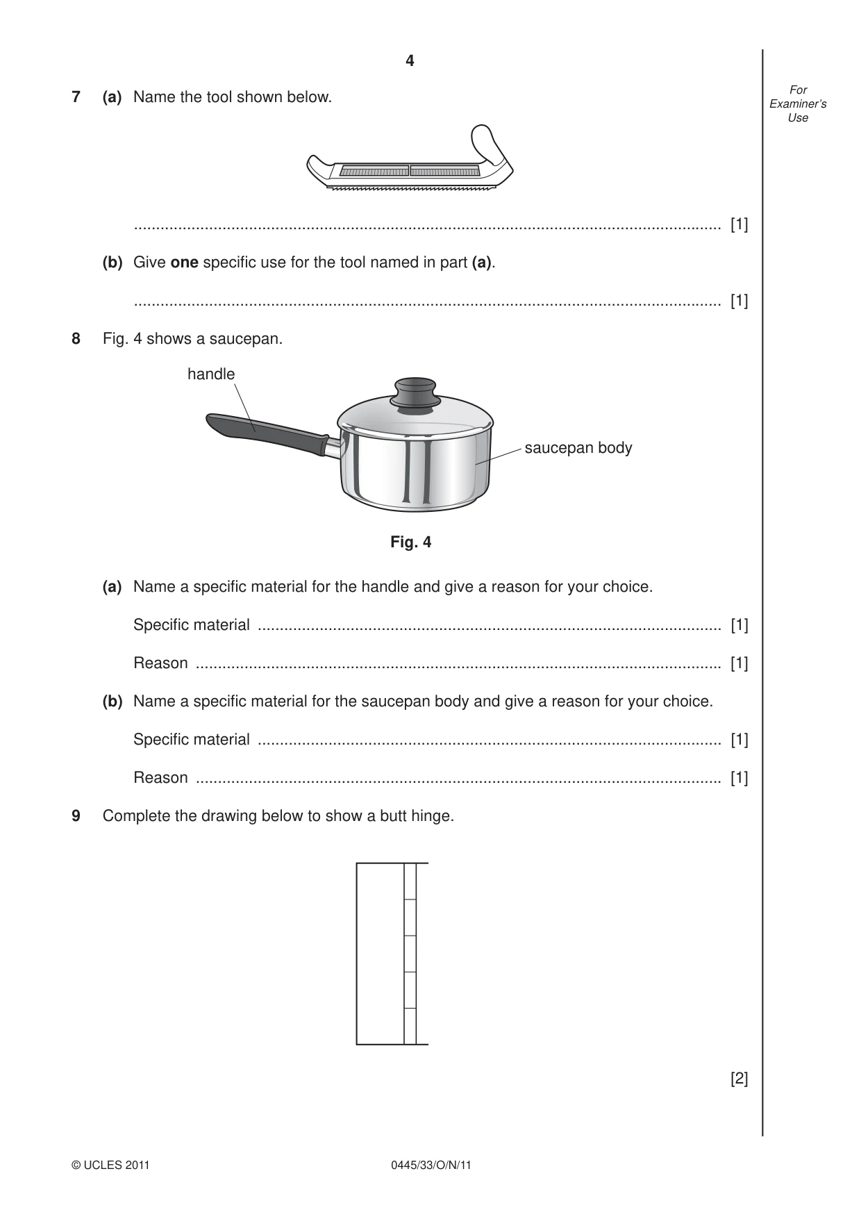
4 0445/33/O/N/11 © UCLES 2011 For Examiner’s Use 7 (a) Name the tool shown below. … [1] (b) Give one specifi c use for the tool named in part (a). … [1] 8 Fig. 4 shows a saucepan. handle saucepan body Fig. 4 (a) Name a specifi c material for the handle and give a reason for your choice. Specifi c material … [1] Reason … [1] (b) Name a specifi c material for the saucepan body and give a reason for your choice. Specifi c material … [1] Reason … [1] 9 Complete the drawing below to show a butt hinge. [2]
Question paper, page 5
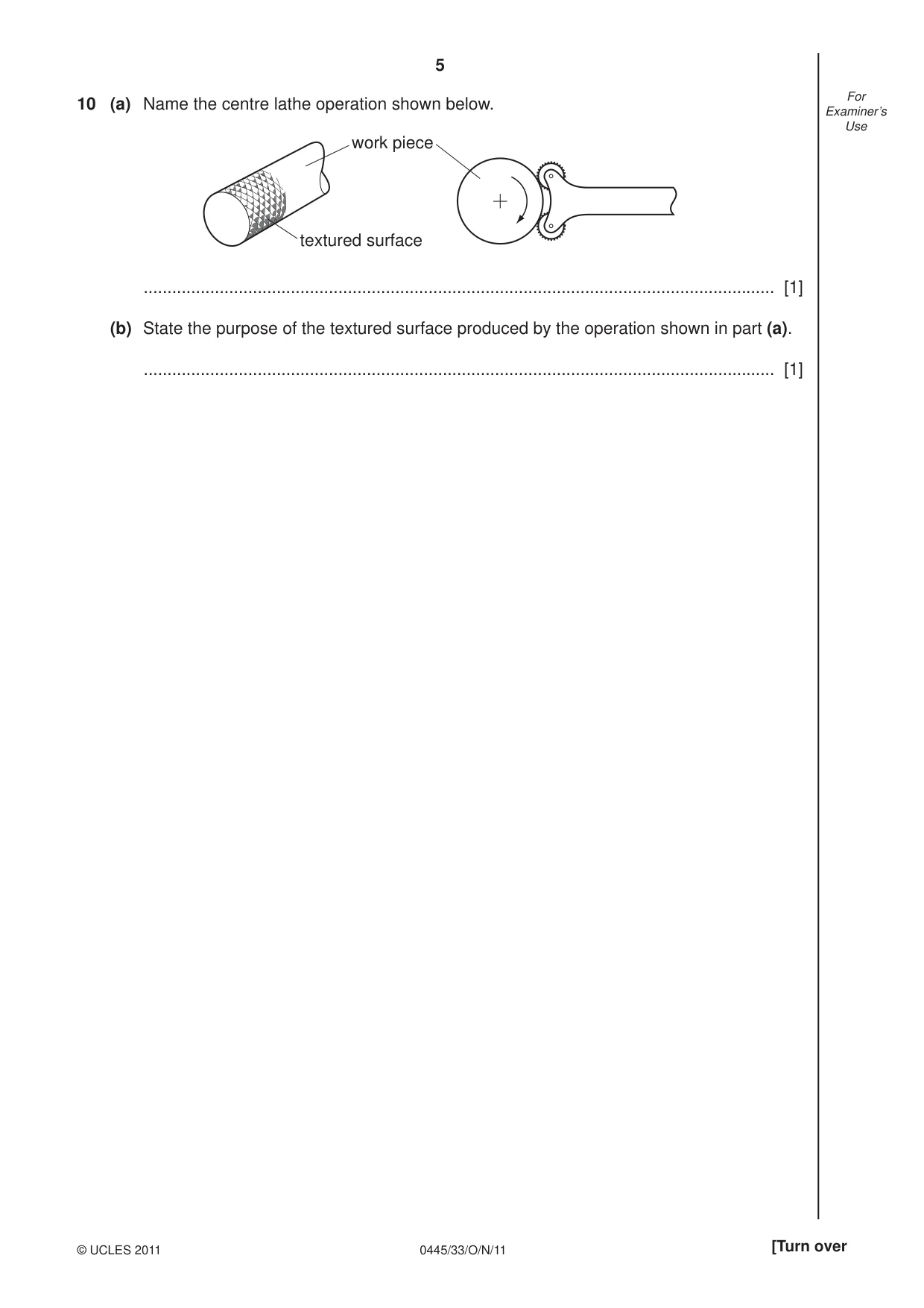
5 0445/33/O/N/11 © UCLES 2011 [Turn over For Examiner’s Use 10 (a) Name the centre lathe operation shown below. work piece textured surface … [1] (b) State the purpose of the textured surface produced by the operation shown in part (a). … [1]
Question paper, page 6
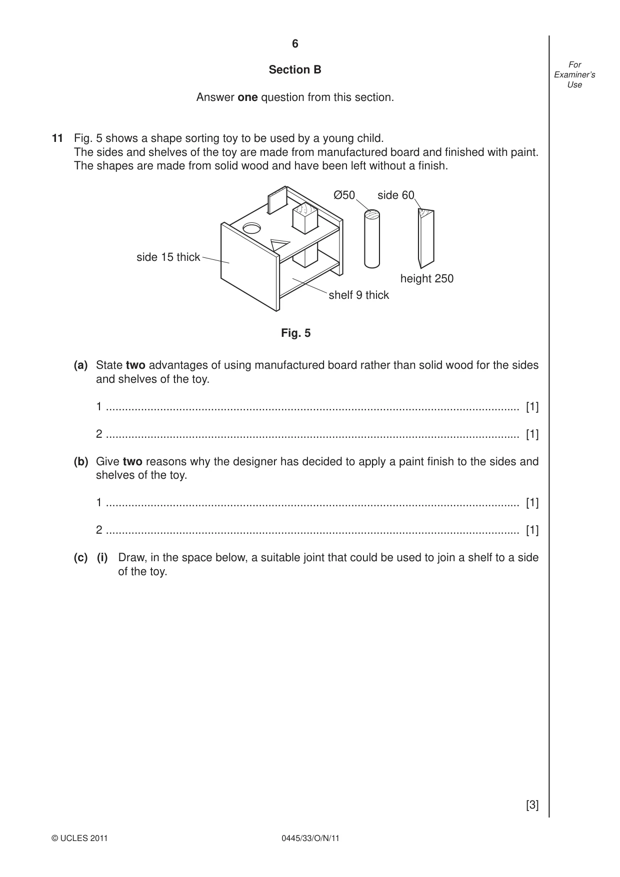
6 0445/33/O/N/11 © UCLES 2011 For Examiner’s Use Section B Answer one question from this section. 11 Fig. 5 shows a shape sorting toy to be used by a young child. The sides and shelves of the toy are made from manufactured board and fi nished with paint. The shapes are made from solid wood and have been left without a fi nish. side 15 thick shelf 9 thick height 250 side 60 Ø50 Fig. 5 (a) State two advantages of using manufactured board rather than solid wood for the sides and shelves of the toy. 1 … [1] 2 … [1] (b) Give two reasons why the designer has decided to apply a paint fi nish to the sides and shelves of the toy. 1 … [1] 2 … [1] (c) (i) Draw, in the space below, a suitable joint that could be used to join a shelf to a side of the toy. [3]
Question paper, page 7
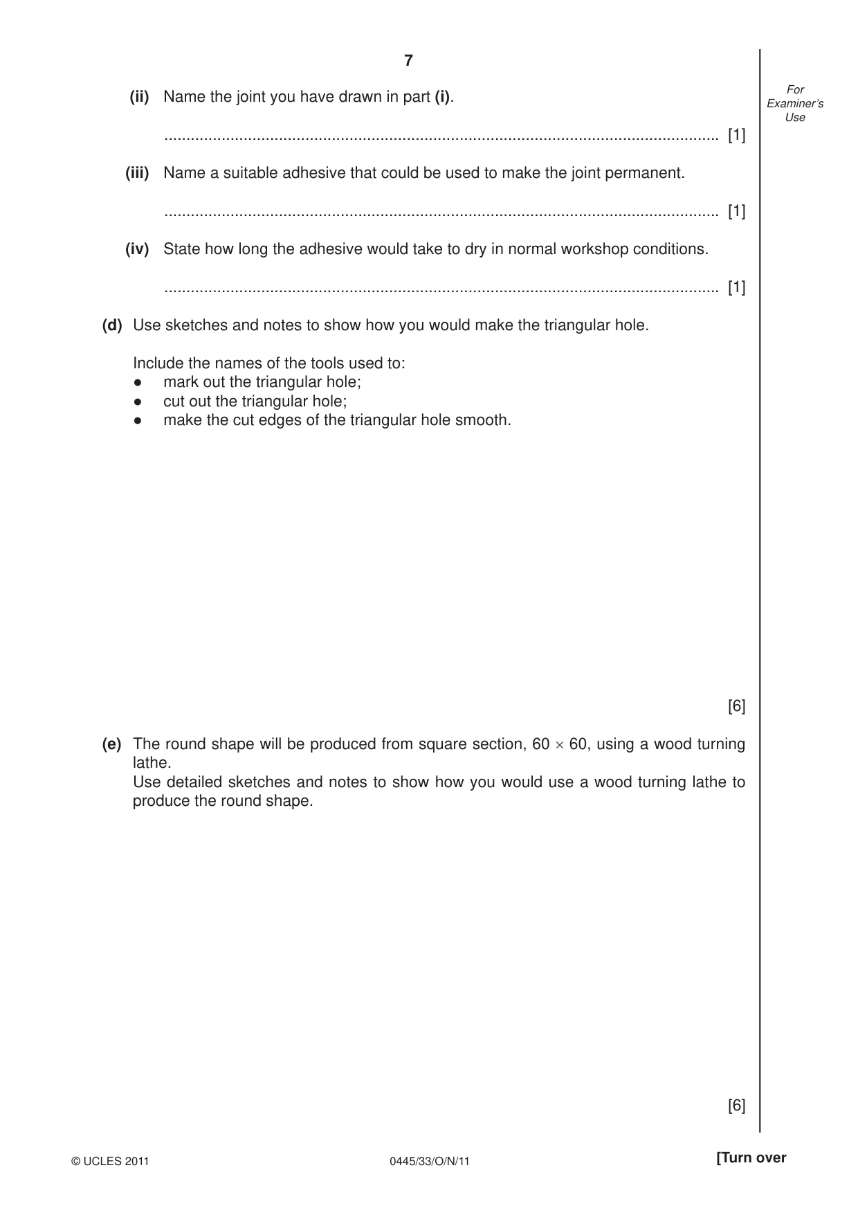
7 0445/33/O/N/11 © UCLES 2011 [Turn over For Examiner’s Use (ii) Name the joint you have drawn in part (i). … [1] (iii) Name a suitable adhesive that could be used to make the joint permanent. … [1] (iv) State how long the adhesive would take to dry in normal workshop conditions. … [1] (d) Use sketches and notes to show how you would make the triangular hole. Include the names of the tools used to: ● mark out the triangular hole; ● cut out the triangular hole; ● make the cut edges of the triangular hole smooth. [6] (e) The round shape will be produced from square section, 60 × 60, using a wood turning lathe. Use detailed sketches and notes to show how you would use a wood turning lathe to produce the round shape. [6]
Question paper, page 8
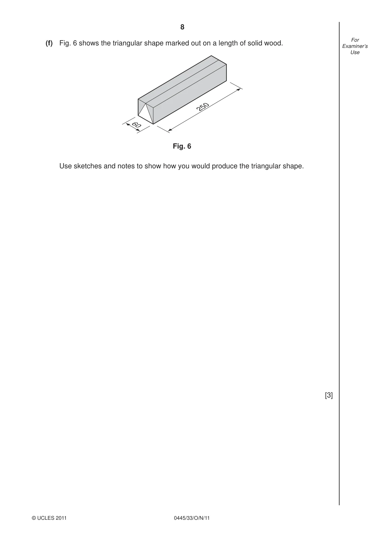
8 0445/33/O/N/11 © UCLES 2011 For Examiner’s Use (f) Fig. 6 shows the triangular shape marked out on a length of solid wood. 60 250 Fig. 6 Use sketches and notes to show how you would produce the triangular shape. [3]
Question paper, page 9
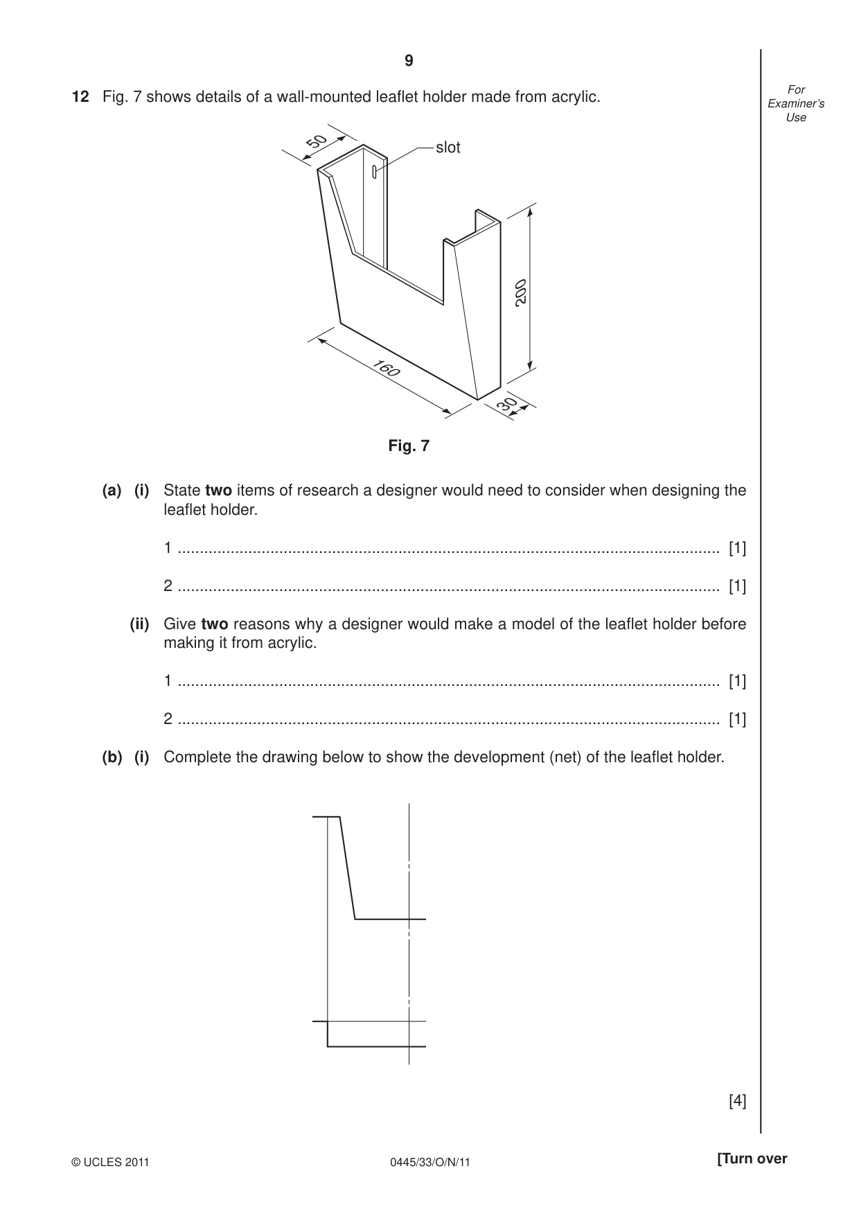
9 0445/33/O/N/11 © UCLES 2011 [Turn over For Examiner’s Use 12 Fig. 7 shows details of a wall-mounted leafl et holder made from acrylic. 160 30 50 200 slot Fig. 7 (a) (i) State two items of research a designer would need to consider when designing the leafl et holder. 1 … [1] 2 … [1] (ii) Give two reasons why a designer would make a model of the leafl et holder before making it from acrylic. 1 … [1] 2 … [1] (b) (i) Complete the drawing below to show the development (net) of the leafl et holder. [4]
Question paper, page 10
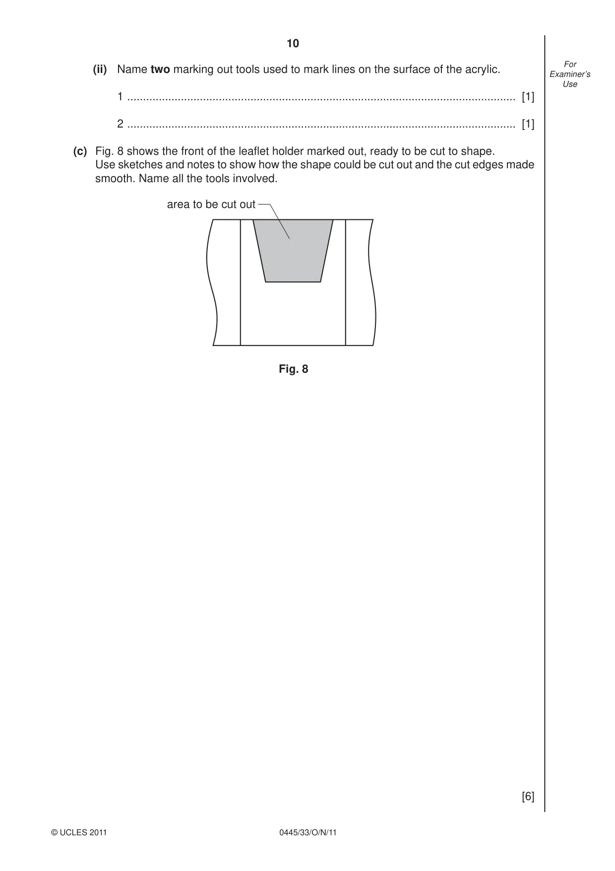
10 0445/33/O/N/11 © UCLES 2011 For Examiner’s Use (ii) Name two marking out tools used to mark lines on the surface of the acrylic. 1 … [1] 2 … [1] (c) Fig. 8 shows the front of the leafl et holder marked out, ready to be cut to shape. Use sketches and notes to show how the shape could be cut out and the cut edges made smooth. Name all the tools involved. area to be cut out Fig. 8 [6]
Question paper, page 11
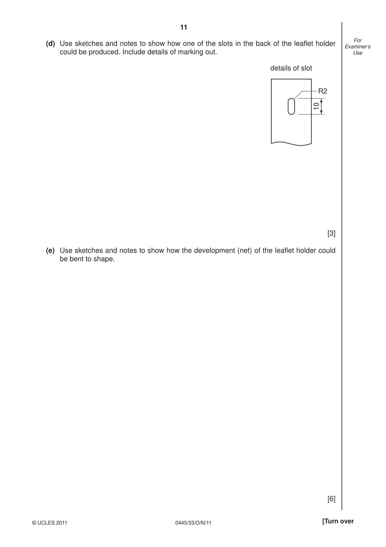
11 0445/33/O/N/11 © UCLES 2011 [Turn over For Examiner’s Use (d) Use sketches and notes to show how one of the slots in the back of the leafl et holder could be produced. Include details of marking out. R2 10 details of slot [3] (e) Use sketches and notes to show how the development (net) of the leafl et holder could be bent to shape. [6]
Question paper, page 12
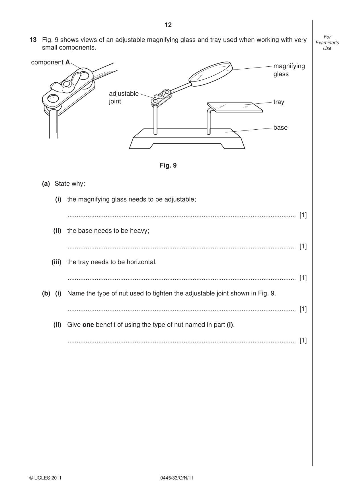
12 0445/33/O/N/11 © UCLES 2011 For Examiner’s Use 13 Fig. 9 shows views of an adjustable magnifying glass and tray used when working with very small components. component A magnifying glass tray base adjustable joint Fig. 9 (a) State why: (i) the magnifying glass needs to be adjustable; … [1] (ii) the base needs to be heavy; … [1] (iii) the tray needs to be horizontal. … [1] (b) (i) Name the type of nut used to tighten the adjustable joint shown in Fig. 9. … [1] (ii) Give one benefi t of using the type of nut named in part (i). … [1]
Question paper, page 13
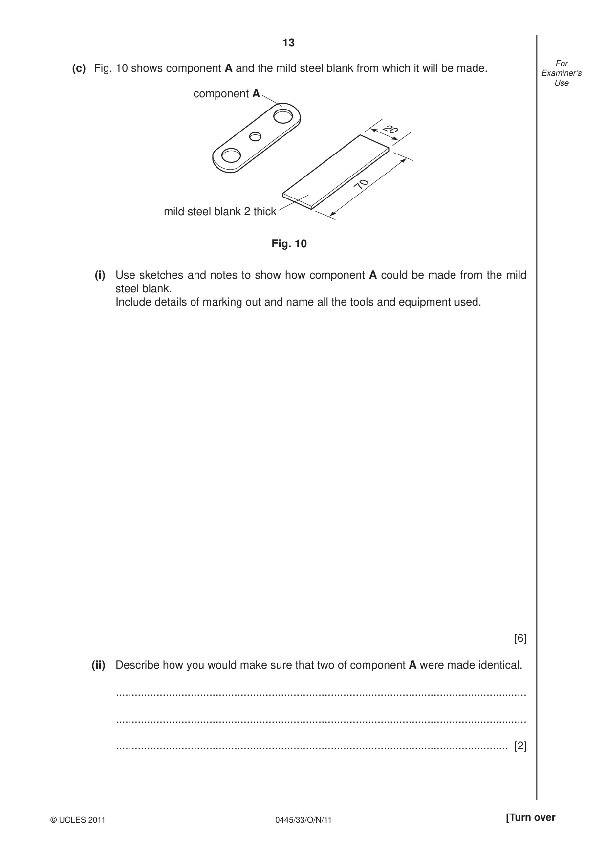
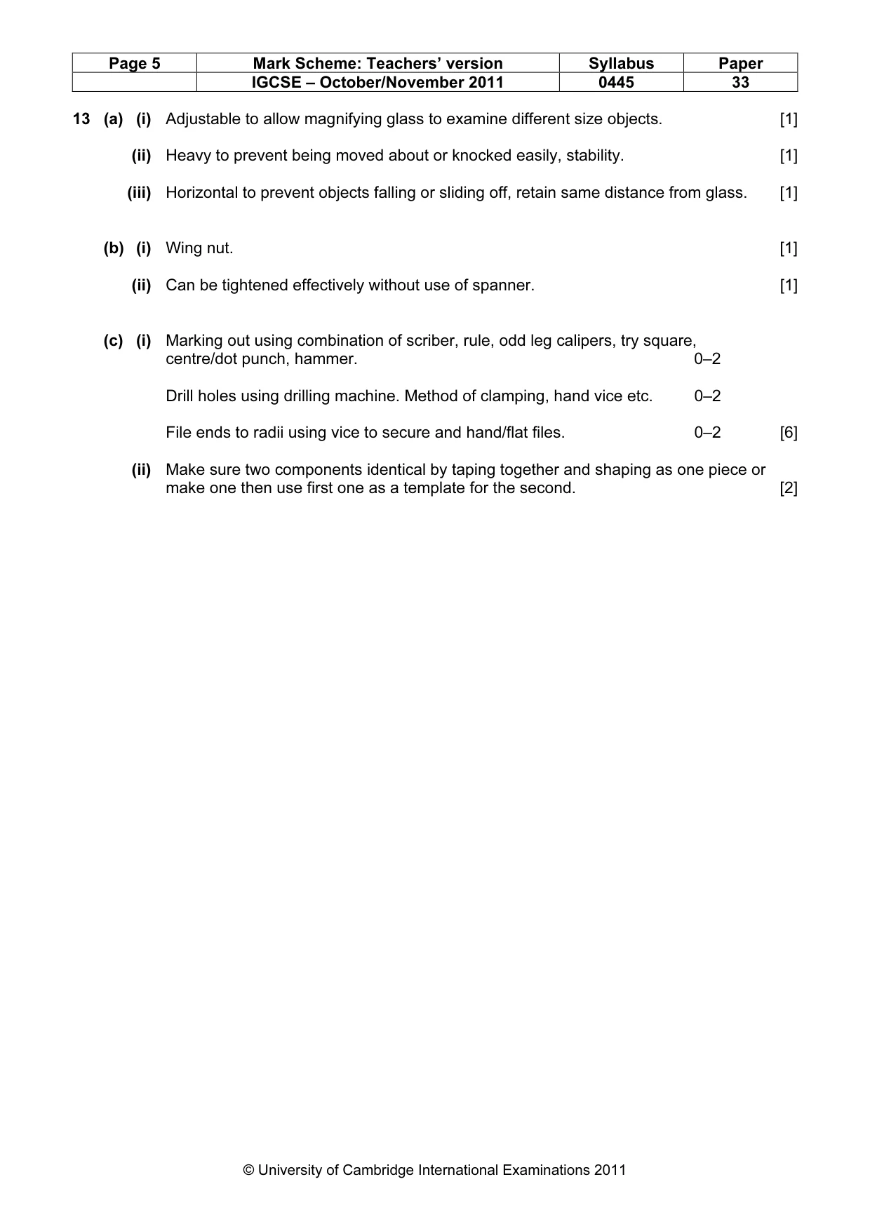
13 0445/33/O/N/11 © UCLES 2011 [Turn over For Examiner’s Use (c) Fig. 10 shows component A and the mild steel blank from which it will be made. component A mild steel blank 2 thick 20 70 Fig. 10 (i) Use sketches and notes to show how component A could be made from the mild steel blank. Include details of marking out and name all the tools and equipment used. [6] (ii) Describe how you would make sure that two of component A were made identical. … … … [2]
Question paper, page 14
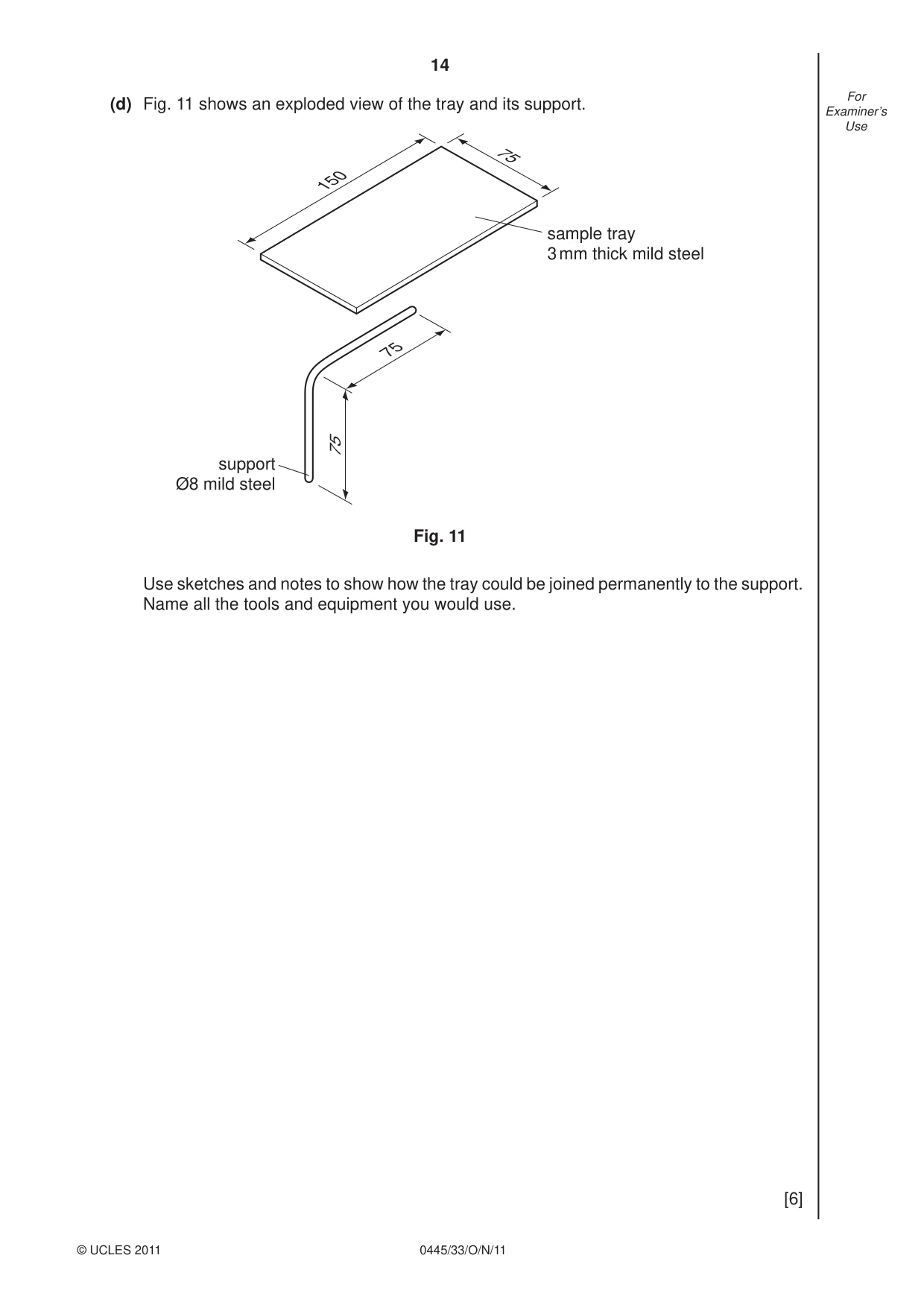
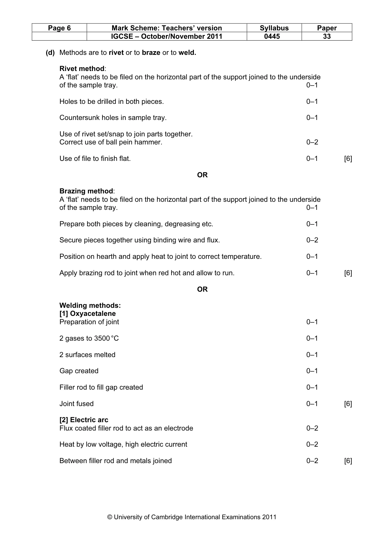
14 0445/33/O/N/11 © UCLES 2011 For Examiner’s Use (d) Fig. 11 shows an exploded view of the tray and its support. 75 75 150 75 support Ø8 mild steel sample tray 3 mm thick mild steel Fig. 11 Use sketches and notes to show how the tray could be joined permanently to the support. Name all the tools and equipment you would use. [6]
Question paper, page 15
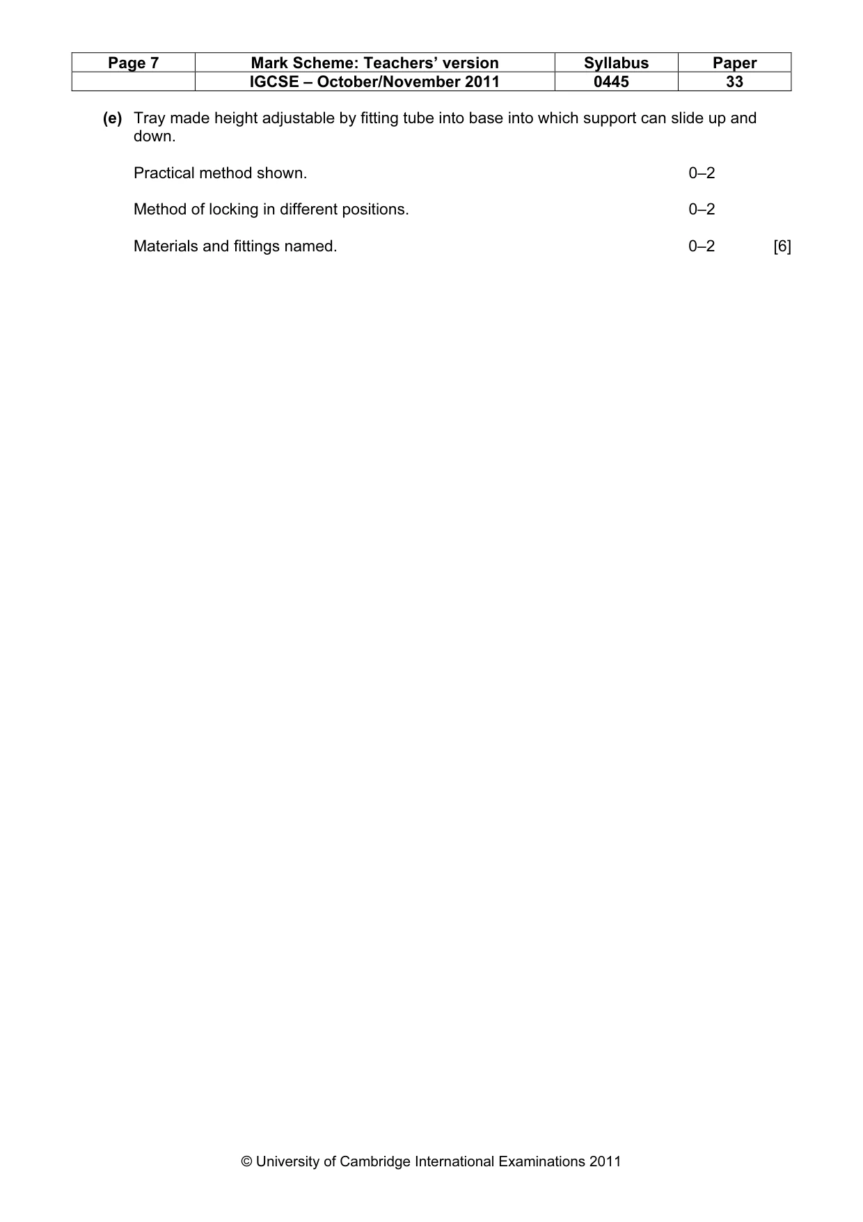
15 0445/33/O/N/11 © UCLES 2011 [Turn over For Examiner’s Use (e) Use sketches and notes to show how the tray could be made adjustable in height and remain horizontal. The tray must be locked securely at different heights. Name any materials and fi ttings used. [6]
Question paper, page 16
16 0445/33/O/N/11 Permission to reproduce items where third-party owned material protected by copyright is included has been sought and cleared where possible. Every reasonable effort has been made by the publisher (UCLES) to trace copyright holders, but if any items requiring clearance have unwittingly been included the publisher will be pleased to make amends at the earliest possible opportunity. University of Cambridge International Examinations is part of the Cambridge Assessment Group. Cambridge Assessment is the brand name of University of Cambridge Local Examinations Syndicate (UCLES), which is itself a department of the University of Cambridge. BLANK PAGE © UCLES 2011
Mark scheme, page 1
UNIVERSITY OF CAMBRIDGE INTERNATIONAL EXAMINATIONS International General Certificate of Secondary Education MARK SCHEME for the October/November 2011 question paper for the guidance of teachers 0445 DESIGN AND TECHNOLOGY 0445/33 Paper 3 (Resistant Materials), maximum raw mark 50 This mark scheme is published as an aid to teachers and candidates, to indicate the requirements of the examination. It shows the basis on which Examiners were instructed to award marks. It does not indicate the details of the discussions that took place at an Examiners’ meeting before marking began, which would have considered the acceptability of alternative answers. Mark schemes must be read in conjunction with the question papers and the report on the examination. • Cambridge will not enter into discussions or correspondence in connection with these mark schemes. Cambridge is publishing the mark schemes for the October/November 2011 question papers for most IGCSE, GCE Advanced Level and Advanced Subsidiary Level syllabuses and some Ordinary Level syllabuses. www.XtremePapers.com
Mark scheme, page 2
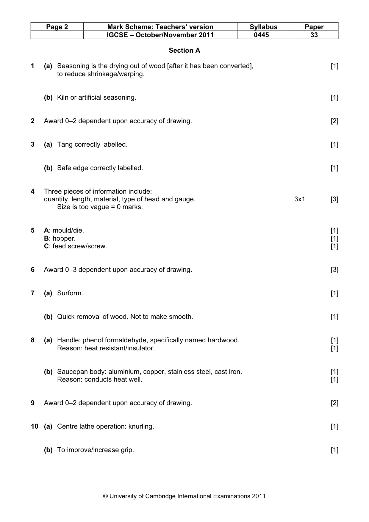
Page 2 Mark Scheme: Teachers’ version Syllabus Paper IGCSE – October/November 2011 0445 33 © University of Cambridge International Examinations 2011 Section A 1 (a) Seasoning is the drying out of wood [after it has been converted], [1] to reduce shrinkage/warping. (b) Kiln or artificial seasoning. [1] 2 Award 0–2 dependent upon accuracy of drawing. [2] 3 (a) Tang correctly labelled. [1] (b) Safe edge correctly labelled. [1] 4 Three pieces of information include: quantity, length, material, type of head and gauge. 3x1 [3] Size is too vague = 0 marks. 5 A: mould/die. [1] B: hopper. [1] C: feed screw/screw. [1] 6 Award 0–3 dependent upon accuracy of drawing. [3] 7 (a) Surform. [1] (b) Quick removal of wood. Not to make smooth. [1] 8 (a) Handle: phenol formaldehyde, specifically named hardwood. [1] Reason: heat resistant/insulator. [1] (b) Saucepan body: aluminium, copper, stainless steel, cast iron. [1] Reason: conducts heat well. [1] 9 Award 0–2 dependent upon accuracy of drawing. [2] 10 (a) Centre lathe operation: knurling. [1] (b) To improve/increase grip. [1]
Mark scheme, page 3
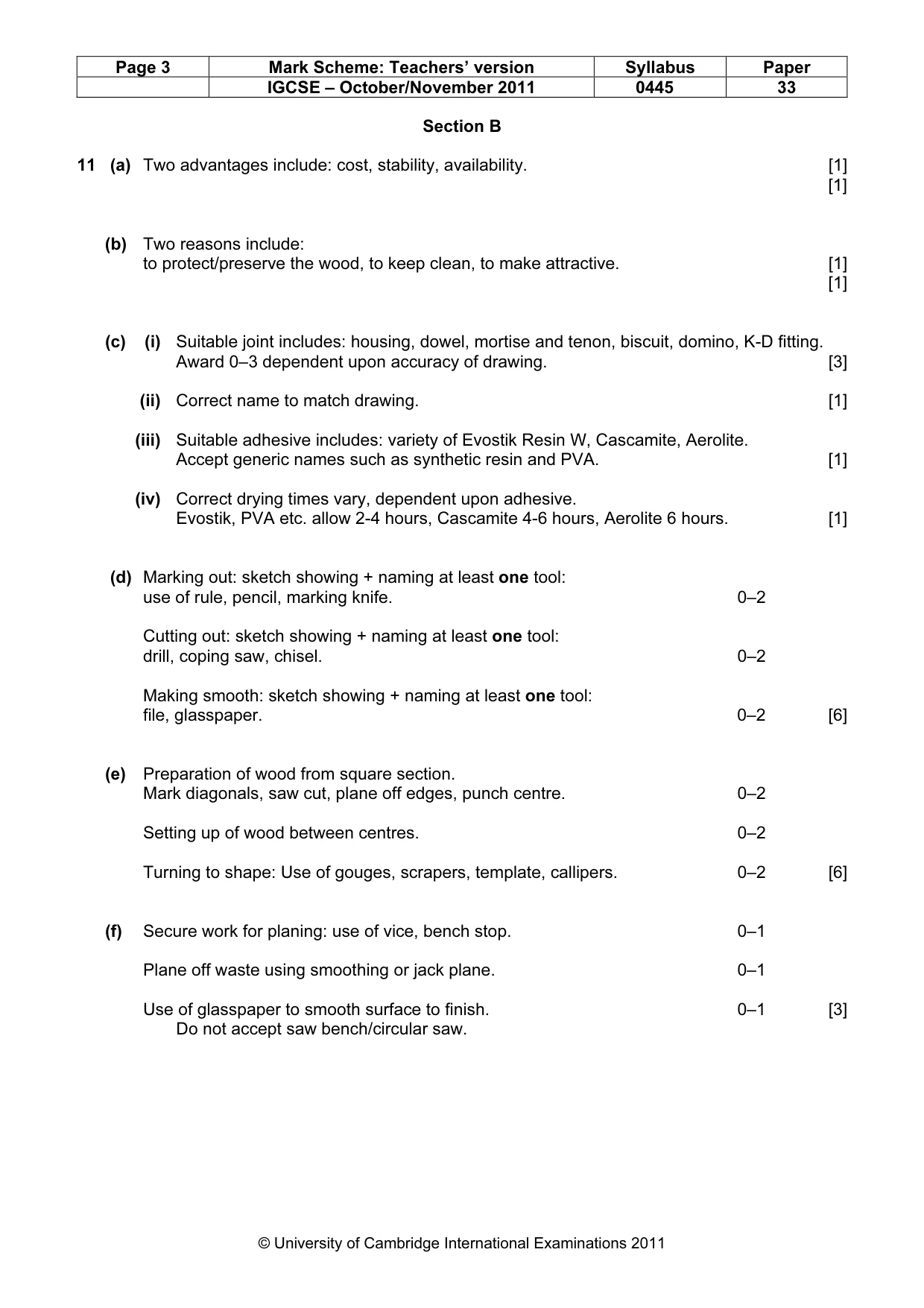
Page 3 Mark Scheme: Teachers’ version Syllabus Paper IGCSE – October/November 2011 0445 33 © University of Cambridge International Examinations 2011 Section B 11 (a) Two advantages include: cost, stability, availability. [1] [1] (b) Two reasons include: to protect/preserve the wood, to keep clean, to make attractive. [1] [1] (c) (i) Suitable joint includes: housing, dowel, mortise and tenon, biscuit, domino, K-D fitting. Award 0–3 dependent upon accuracy of drawing. [3] (ii) Correct name to match drawing. [1] (iii) Suitable adhesive includes: variety of Evostik Resin W, Cascamite, Aerolite. Accept generic names such as synthetic resin and PVA. [1] (iv) Correct drying times vary, dependent upon adhesive. Evostik, PVA etc. allow 2-4 hours, Cascamite 4-6 hours, Aerolite 6 hours. [1] (d) Marking out: sketch showing + naming at least one tool: use of rule, pencil, marking knife. 0–2 Cutting out: sketch showing + naming at least one tool: drill, coping saw, chisel. 0–2 Making smooth: sketch showing + naming at least one tool: file, glasspaper. 0–2 [6] (e) Preparation of wood from square section. Mark diagonals, saw cut, plane off edges, punch centre. 0–2 Setting up of wood between centres. 0–2 Turning to shape: Use of gouges, scrapers, template, callipers. 0–2 [6] (f) Secure work for planing: use of vice, bench stop. 0–1 Plane off waste using smoothing or jack plane. 0–1 Use of glasspaper to smooth surface to finish. 0–1 [3] Do not accept saw bench/circular saw.
Mark scheme, page 4
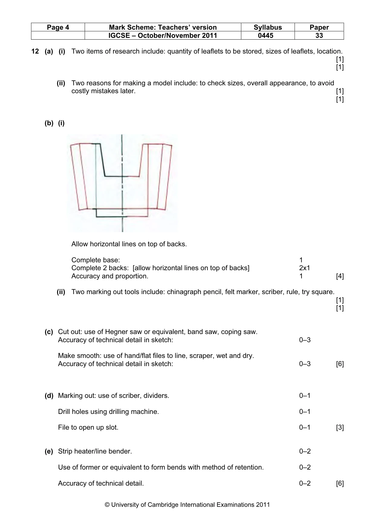
Page 4 Mark Scheme: Teachers’ version Syllabus Paper IGCSE – October/November 2011 0445 33 © University of Cambridge International Examinations 2011 12 (a) (i) Two items of research include: quantity of leaflets to be stored, sizes of leaflets, location. [1] [1] (ii) Two reasons for making a model include: to check sizes, overall appearance, to avoid costly mistakes later. [1] [1] (b) (i) Allow horizontal lines on top of backs. Complete base: 1 Complete 2 backs: [allow horizontal lines on top of backs] 2x1 Accuracy and proportion. 1 [4] (ii) Two marking out tools include: chinagraph pencil, felt marker, scriber, rule, try square. [1] [1] (c) Cut out: use of Hegner saw or equivalent, band saw, coping saw. Accuracy of technical detail in sketch: 0–3 Make smooth: use of hand/flat files to line, scraper, wet and dry. Accuracy of technical detail in sketch: 0–3 [6] (d) Marking out: use of scriber, dividers. 0–1 Drill holes using drilling machine. 0–1 File to open up slot. 0–1 [3] (e) Strip heater/line bender. 0–2 Use of former or equivalent to form bends with method of retention. 0–2 Accuracy of technical detail. 0–2 [6]
Mark scheme, page 5
Page 5 Mark Scheme: Teachers’ version Syllabus Paper IGCSE – October/November 2011 0445 33 © University of Cambridge International Examinations 2011 13 (a) (i) Adjustable to allow magnifying glass to examine different size objects. [1] (ii) Heavy to prevent being moved about or knocked easily, stability. [1] (iii) Horizontal to prevent objects falling or sliding off, retain same distance from glass. [1] (b) (i) Wing nut. [1] (ii) Can be tightened effectively without use of spanner. [1] (c) (i) Marking out using combination of scriber, rule, odd leg calipers, try square, centre/dot punch, hammer. 0–2 Drill holes using drilling machine. Method of clamping, hand vice etc. 0–2 File ends to radii using vice to secure and hand/flat files. 0–2 [6] (ii) Make sure two components identical by taping together and shaping as one piece or make one then use first one as a template for the second. [2]
Mark scheme, page 6
Page 6 Mark Scheme: Teachers’ version Syllabus Paper IGCSE – October/November 2011 0445 33 © University of Cambridge International Examinations 2011 (d) Methods are to rivet or to braze or to weld. Rivet method: A ‘flat’ needs to be filed on the horizontal part of the support joined to the underside of the sample tray. 0–1 Holes to be drilled in both pieces. 0–1 Countersunk holes in sample tray. 0–1 Use of rivet set/snap to join parts together. Correct use of ball pein hammer. 0–2 Use of file to finish flat. 0–1 [6] OR Brazing method: A ‘flat’ needs to be filed on the horizontal part of the support joined to the underside of the sample tray. 0–1 Prepare both pieces by cleaning, degreasing etc. 0–1 Secure pieces together using binding wire and flux. 0–2 Position on hearth and apply heat to joint to correct temperature. 0–1 Apply brazing rod to joint when red hot and allow to run. 0–1 [6] OR Welding methods: [1] Oxyacetalene Preparation of joint 0–1 2 gases to 3500 °C 0–1 2 surfaces melted 0–1 Gap created 0–1 Filler rod to fill gap created 0–1 Joint fused 0–1 [6] [2] Electric arc Flux coated filler rod to act as an electrode 0–2 Heat by low voltage, high electric current 0–2 Between filler rod and metals joined 0–2 [6]
Mark scheme, page 7
Page 7 Mark Scheme: Teachers’ version Syllabus Paper IGCSE – October/November 2011 0445 33 © University of Cambridge International Examinations 2011 (e) Tray made height adjustable by fitting tube into base into which support can slide up and down. Practical method shown. 0–2 Method of locking in different positions. 0–2 Materials and fittings named. 0–2 [6]