Cambridge A Level Physics 9702 — 2011 May/June Paper 2 · Variant 1
9702/21/M/J/11 · 7 questions · 60 marks · ≈68 min
The question paper and its mark scheme, free to read here and free to download. This is Cambridge’s own paper, exactly as it was sat.
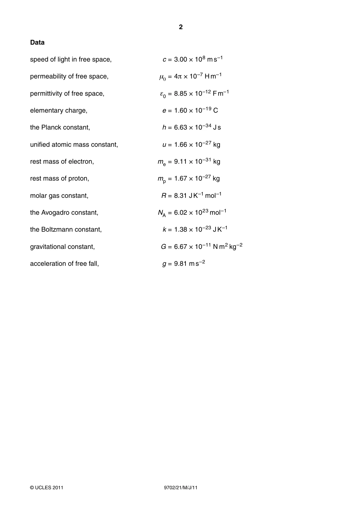
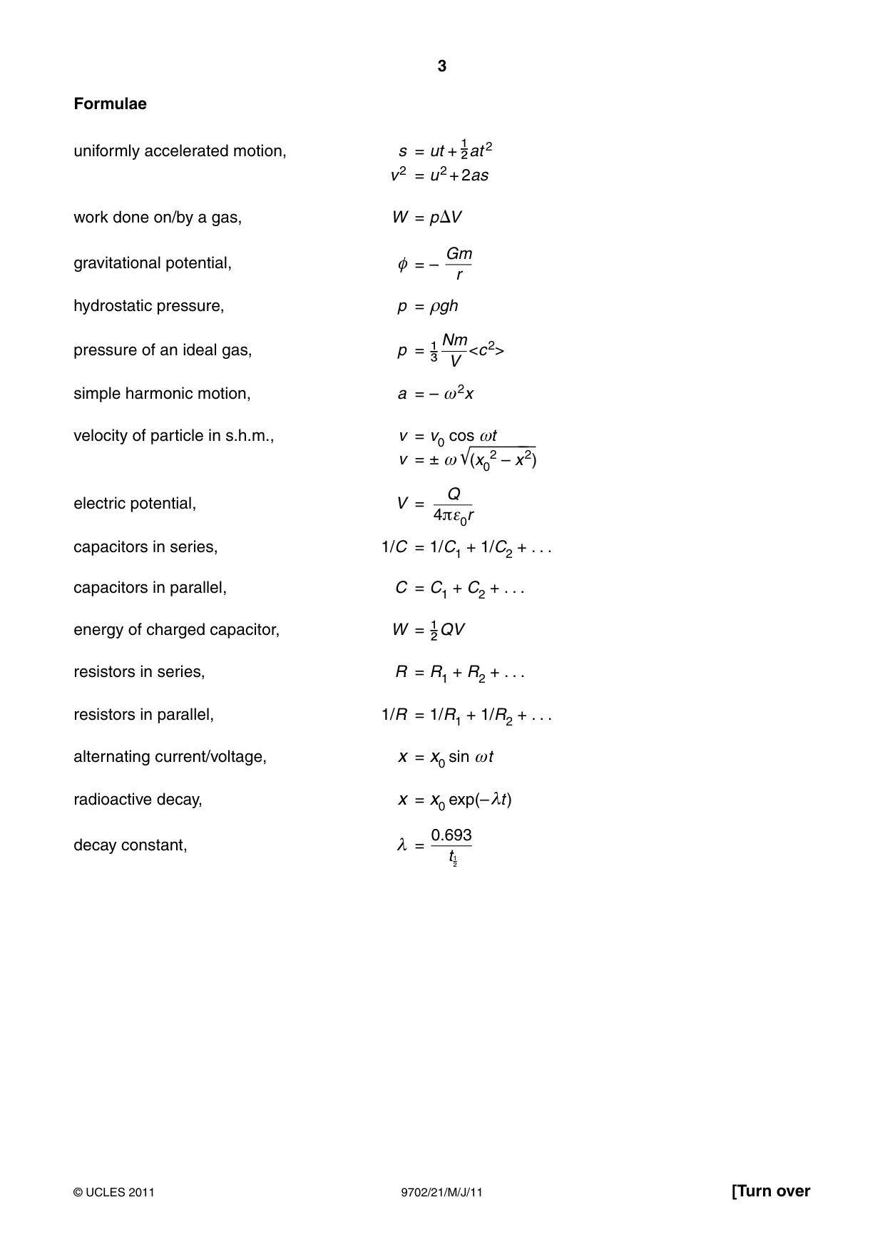
Question paper16 pages
Mark scheme4 pages
Answers below. Sit the paper first if you are practising.
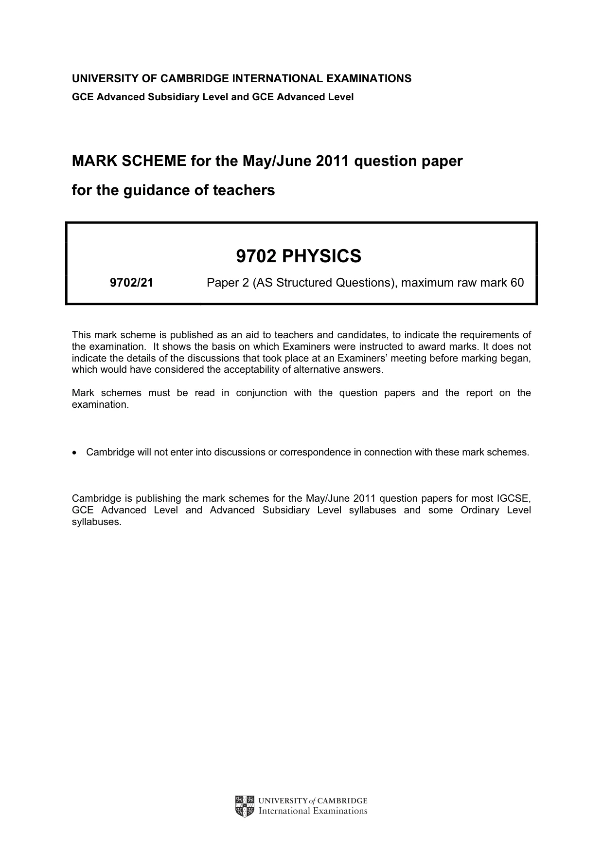
Questions as text
Q1 · Measurements made for a sample of metal wire are shown in Fig
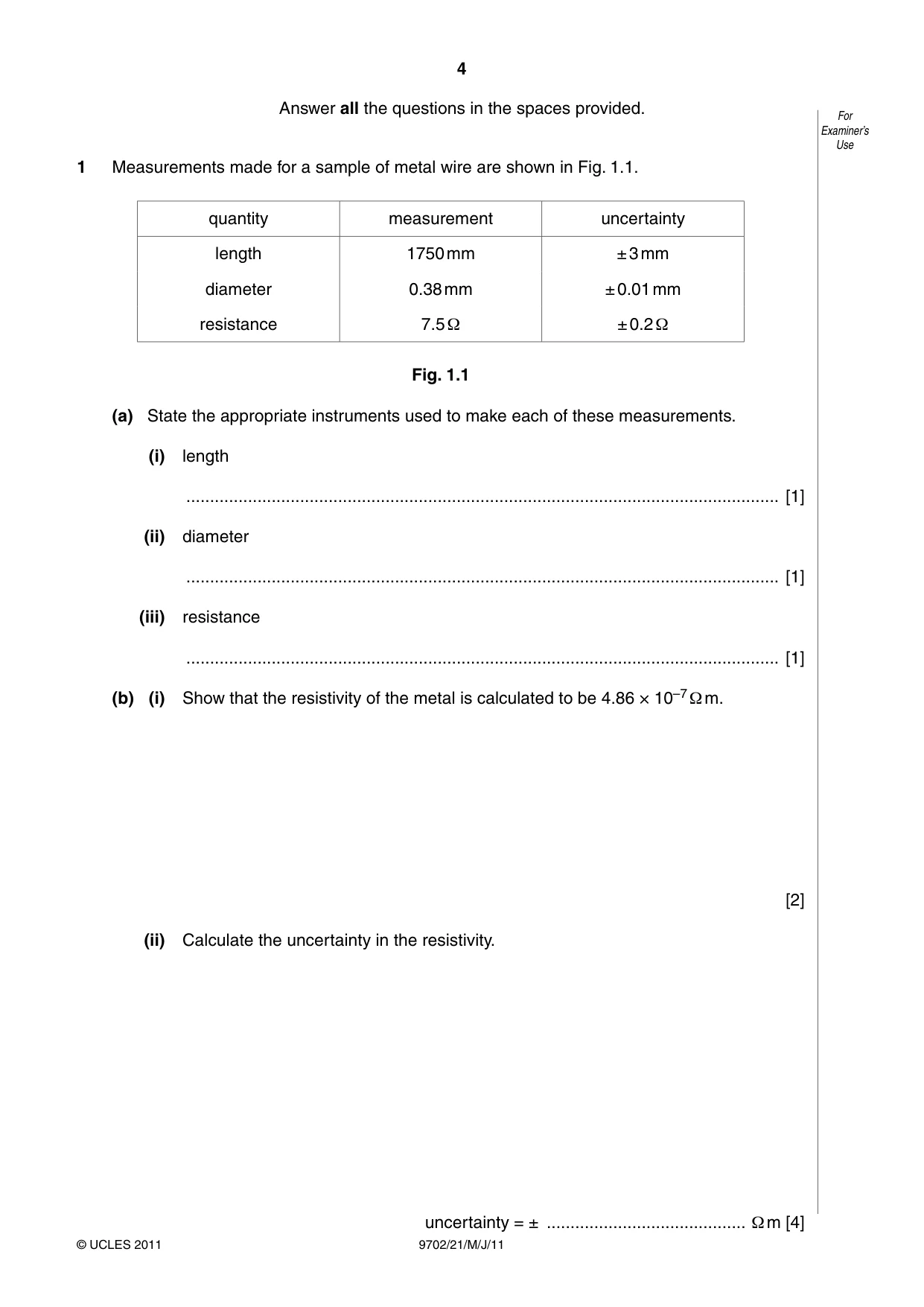
1 Measurements made for a sample of metal wire are shown in Fig. 1.1. quantity measurement uncertainty length 1750 mm ± 3 mm diameter 0.38 mm ± 0.01 mm resistance 7.5 Ω ± 0.2 Ω Fig. 1.1 (a) State the appropriate instruments used to make each of these measurements. (i) length ............................................................................................................................. [1] (ii) diameter ............................................................................................................................. [1] (iii) resistance ............................................................................................................................. [1] (b) (i) Show that the resistivity of the metal is calculated to be 4.86 × 10⁻⁷ Ω m. [2] (ii) Calculate the uncertainty in the resistivity. uncertainty = ± .......................................... Ω m [4] (c) Use the answers in (b) to express the resistivity with its uncertainty to the appropriate For number of significant figures. Examiner’s Use resistivity = .......................................... ± .......................................... Ω m [1]
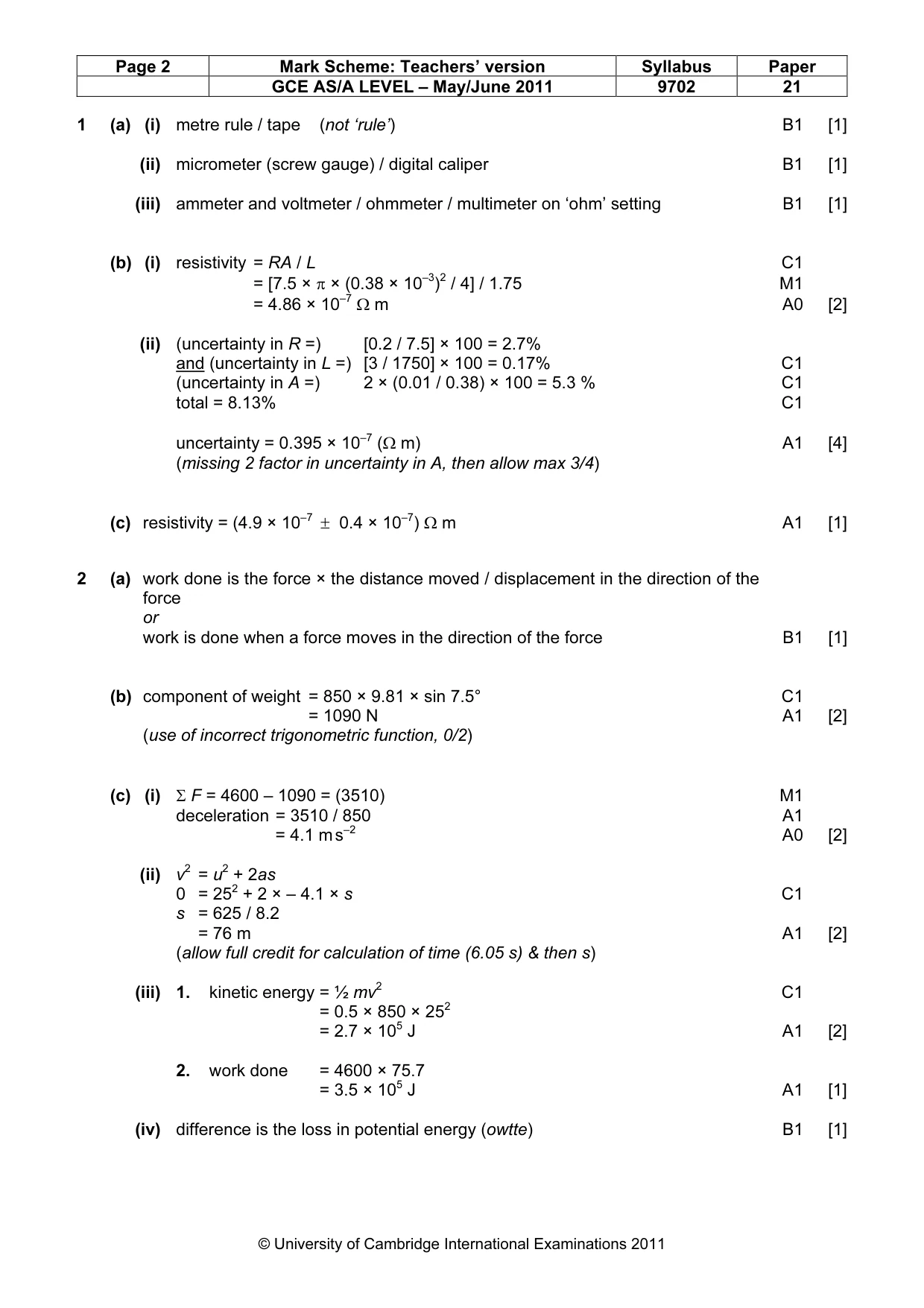
Mark scheme: 1 (a) (i) metre rule / tape (not ‘rule’) B1 [1] (ii) micrometer (screw gauge) / digital caliper B1 [1] (iii) ammeter and voltmeter / ohmmeter / multimeter on ‘ohm’ setting B1 [1] (b) (i) resistivity = RA / L C1 = [7.5 × π × (0.38 × 10⁻³)2 / 4] / 1.75 M1 = 4.86 × 10⁻⁷ Ω m A0 [2] (ii) (uncertainty in R =) [0.2 / 7.5] × 100 = 2.7% and (uncertainty in L =) [3 / 1750] × 100 = 0.17% C1 (uncertainty in A =) 2 × (0.01 / 0.38) × 100 = 5.3 % C1 total = 8.13% C1 uncertainty = 0.395 × 10⁻⁷ (Ω m) A1 [4] (missing 2 factor in uncertainty in A, then allow max 3/4) (c) resistivity = (4.9 × 10⁻⁷ ± 0.4 × 10⁻⁷) Ω m A1 [1]
Q2 · Explain what is meant by work done
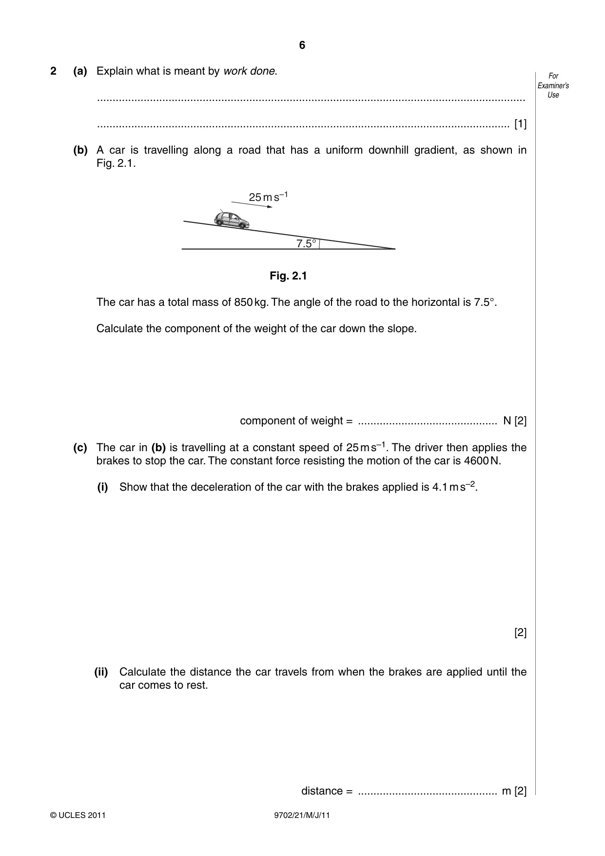
2 (a) Explain what is meant by work done. For Examiner’s .......................................................................................................................................... Use ..................................................................................................................................... [1] (b) A car is travelling along a road that has a uniform downhill gradient, as shown in Fig. 2.1. 25 m s–1 7.5° Fig. 2.1 The car has a total mass of 850 kg. The angle of the road to the horizontal is 7.5°. Calculate the component of the weight of the car down the slope. component of weight = ............................................. N [2] (c) The car in (b) is travelling at a constant speed of 25 m s–1. The driver then applies the brakes to stop the car. The constant force resisting the motion of the car is 4600 N. (i) Show that the deceleration of the car with the brakes applied is 4.1 m s–2. [2] (ii) Calculate the distance the car travels from when the brakes are applied until the car comes to rest. distance = ............................................. m [2] (iii) Calculate For Examiner’s 1. the loss of kinetic energy of the car, Use loss of kinetic energy = .............................................. J [2] 2. the work done by the resisting force of 4600 N. work done = .............................................. J [1] (iv) The quantities in (iii) part 1 and in (iii) part 2 are not equal. Explain why these two quantities are not equal. .................................................................................................................................. ............................................................................................................................. [1]
Mark scheme: 2 (a) work done is the force × the distance moved / displacement in the direction of the force or work is done when a force moves in the direction of the force B1 [1] (b) component of weight = 850 × 9.81 × sin 7.5° C1 = 1090 N A1 [2] (use of incorrect trigonometric function, 0/2) (c) (i) Σ F = 4600 – 1090 = (3510) M1 deceleration = 3510 / 850 A1 = 4.1 m s–2 A0 [2] (ii) v2 = u2 + 2as 0 = 252 + 2 × – 4.1 × s C1 s = 625 / 8.2 = 76 m A1 [2] (allow full credit for calculation of time (6.05 s) & then s) (iii) 1. kinetic energy = ½ mv2 C1 = 0.5 × 850 × 252 = 2.7 × 10⁵ J A1 [2] 2. work done = 4600 × 75.7 = 3.5 × 10⁵ J A1 [1] (iv) difference is the loss in potential energy (owtte) B1 [1] GCE AS/A LEVEL – May/June 2011 9702 21
Q3 · Explain what is meant by centre of gravity
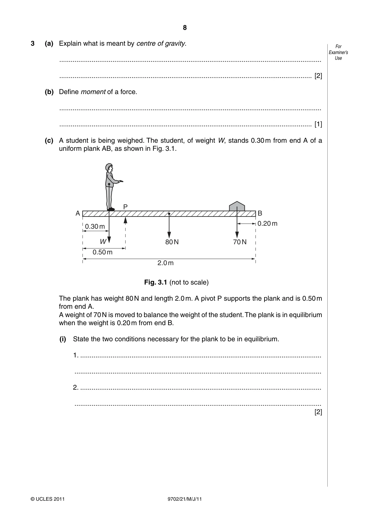
3 (a) Explain what is meant by centre of gravity. For Examiner’s .......................................................................................................................................... Use ..................................................................................................................................... [2] (b) Define moment of a force. .......................................................................................................................................... ..................................................................................................................................... [1] (c) A student is being weighed. The student, of weight W, stands 0.30 m from end A of a uniform plank AB, as shown in Fig. 3.1. P A B 0.20 m 0.30 m W 80 N 70 N 0.50 m 2.0 m Fig. 3.1 (not to scale) The plank has weight 80 N and length 2.0 m. A pivot P supports the plank and is 0.50 m from end A. A weight of 70 N is moved to balance the weight of the student. The plank is in equilibrium when the weight is 0.20 m from end B. (i) State the two conditions necessary for the plank to be in equilibrium. 1. ............................................................................................................................... .................................................................................................................................. 2. ............................................................................................................................... .................................................................................................................................. [2] (ii) Determine the weight W of the student. For Examiner’s Use W = ............................................. N [3] (iii) If only the 70 N weight is moved, there is a maximum weight of student that can be determined using the arrangement shown in Fig. 3.1. State and explain one change that can be made to increase this maximum weight. .................................................................................................................................. .................................................................................................................................. ............................................................................................................................. [2]
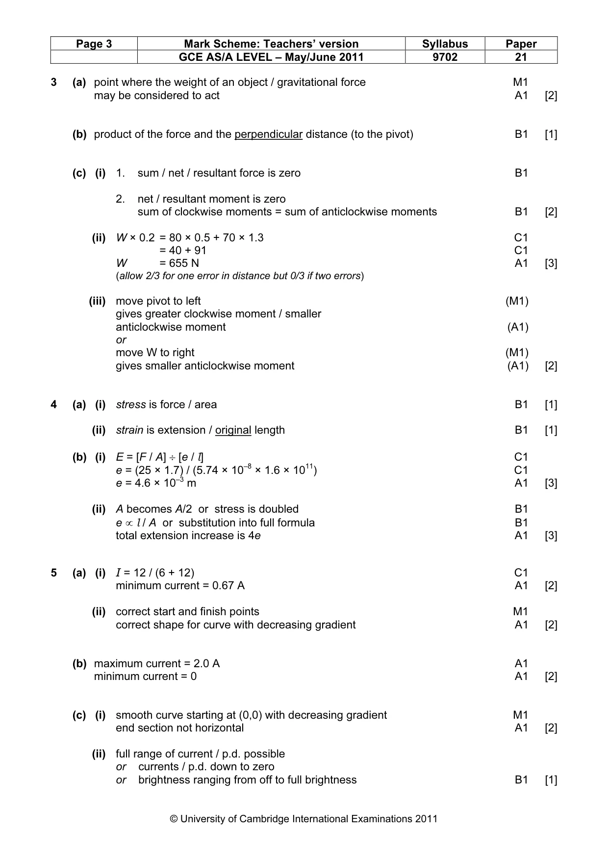
Mark scheme: 3 (a) point where the weight of an object / gravitational force M1 may be considered to act A1 [2] (b) product of the force and the perpendicular distance (to the pivot) B1 [1] (c) (i) 1. sum / net / resultant force is zero B1 2. net / resultant moment is zero sum of clockwise moments = sum of anticlockwise moments B1 [2] (ii) W × 0.2 = 80 × 0.5 + 70 × 1.3 C1 = 40 + 91 C1 W = 655 N A1 [3] (allow 2/3 for one error in distance but 0/3 if two errors) (iii) move pivot to left (M1) gives greater clockwise moment / smaller anticlockwise moment (A1) or move W to right (M1) gives smaller anticlockwise moment (A1) [2]
Q4 · Define, for a wire, For Examiner’s (i) stress, Use…
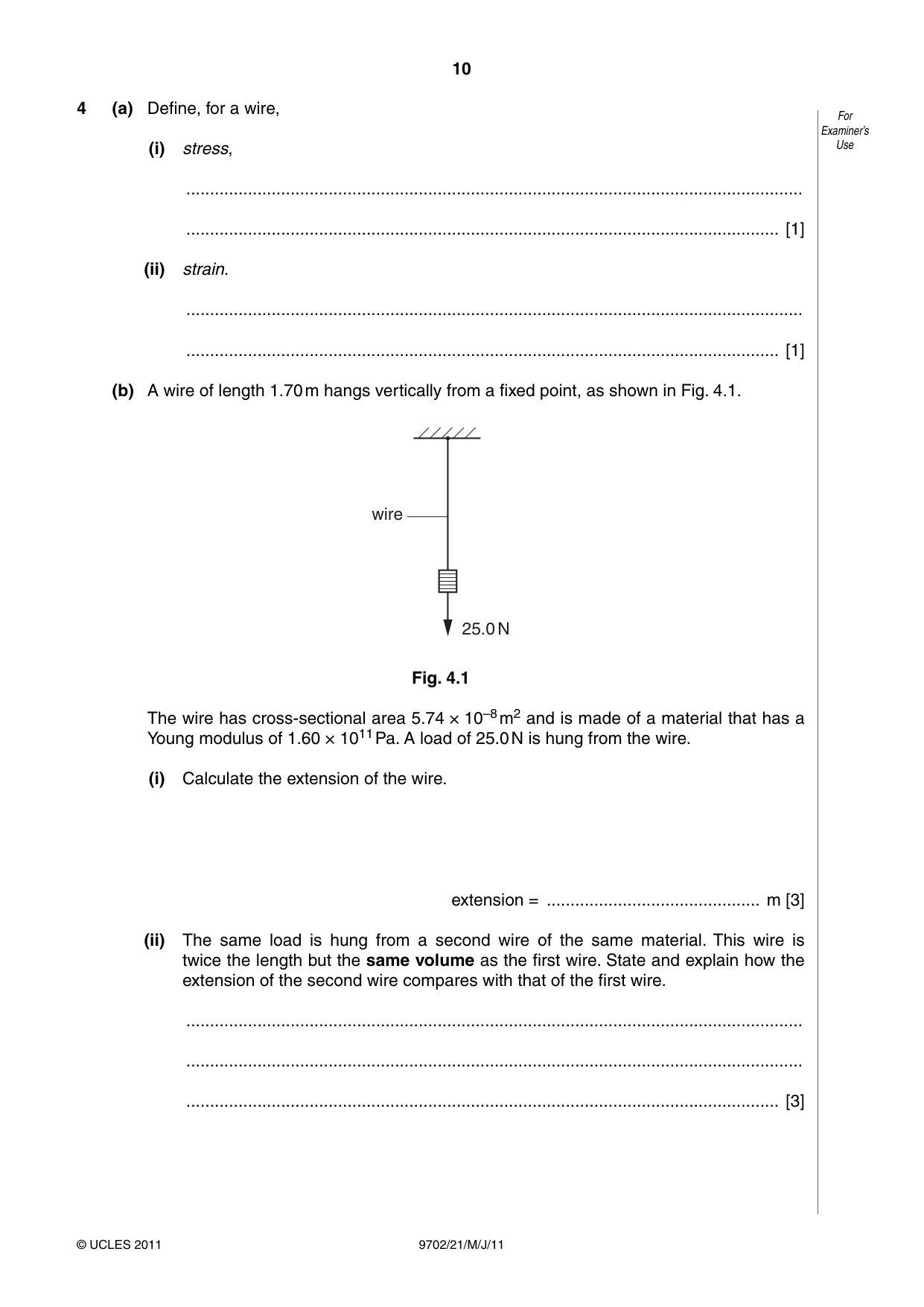
4 (a) Define, for a wire, For Examiner’s (i) stress, Use .................................................................................................................................. ............................................................................................................................. [1] (ii) strain. .................................................................................................................................. ............................................................................................................................. [1] (b) A wire of length 1.70 m hangs vertically from a fixed point, as shown in Fig. 4.1. wire 25.0 N Fig. 4.1 The wire has cross-sectional area 5.74 × 10⁻⁸ m2 and is made of a material that has a Young modulus of 1.60 × 10¹¹ Pa. A load of 25.0 N is hung from the wire. (i) Calculate the extension of the wire. extension = ............................................. m [3] (ii) The same load is hung from a second wire of the same material. This wire is twice the length but the same volume as the first wire. State and explain how the extension of the second wire compares with that of the first wire. .................................................................................................................................. .................................................................................................................................. ............................................................................................................................. [3]
Mark scheme: 4 (a) (i) stress is force / area B1 [1] (ii) strain is extension / original length B1 [1] (b) (i) E = [F / A] ÷ [e / l] C1 e = (25 × 1.7) / (5.74 × 10–8 × 1.6 × 1011) C1 e = 4.6 × 10⁻³ m A1 [3] (ii) A becomes A/2 or stress is doubled B1 e ∝ l / A or substitution into full formula B1 total extension increase is 4e A1 [3]
Q5 · A variable resistor is used to control the current in a circuit, as shown in Fig
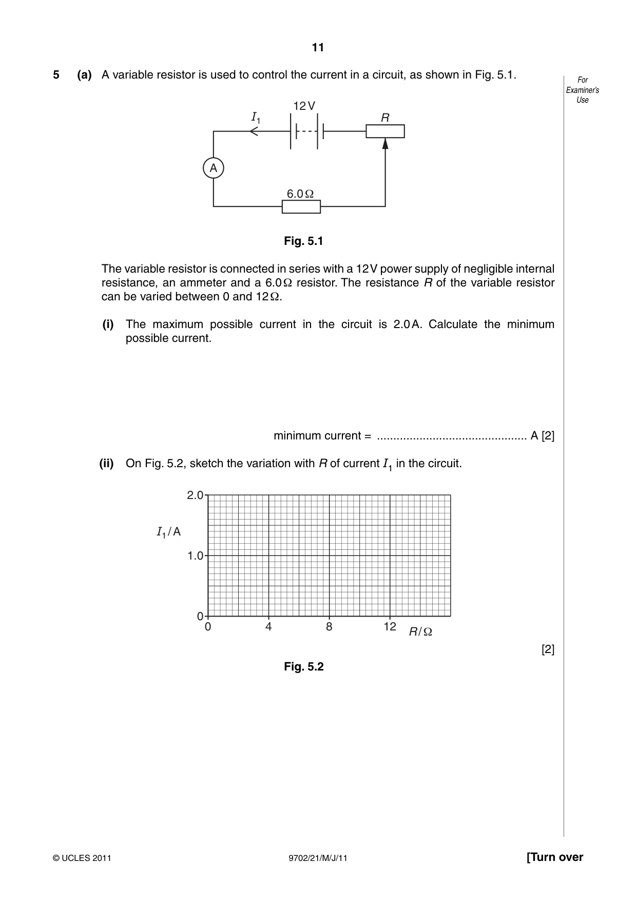
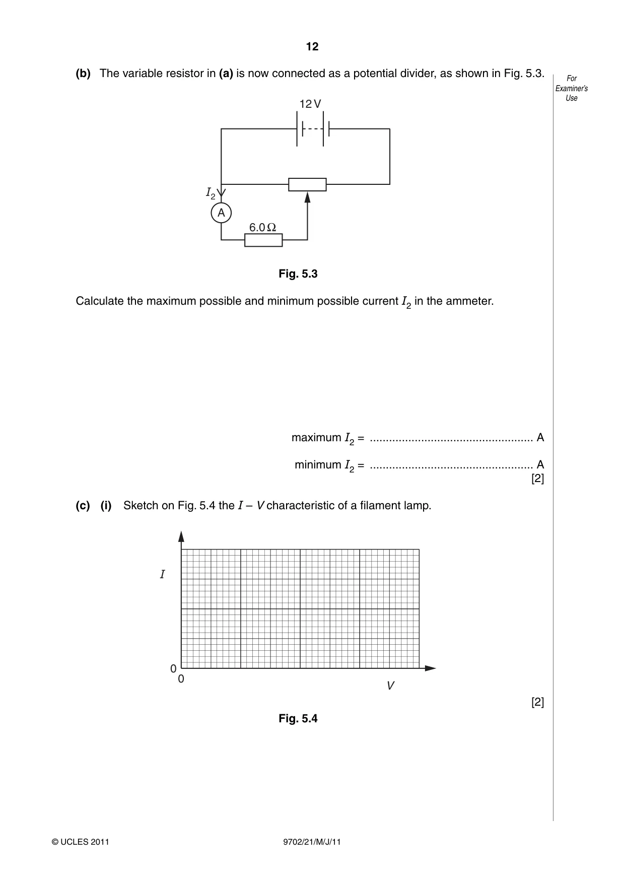
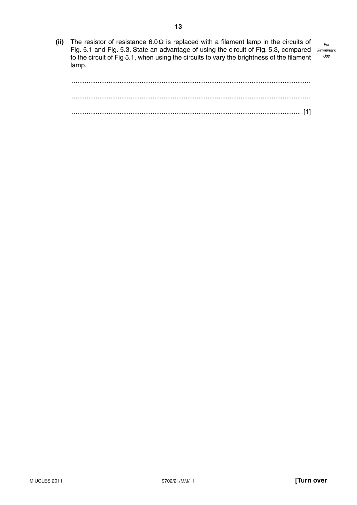
5 (a) A variable resistor is used to control the current in a circuit, as shown in Fig. 5.1. For Examiner’s Use 12 V I1 R A 6.0 Ω Fig. 5.1 The variable resistor is connected in series with a 12 V power supply of negligible internal resistance, an ammeter and a 6.0 Ω resistor. The resistance R of the variable resistor can be varied between 0 and 12 Ω. (i) The maximum possible current in the circuit is 2.0 A. Calculate the minimum possible current. minimum current = .............................................. A [2] (ii) On Fig. 5.2, sketch the variation with R of current I1 in the circuit. 2.0 I1 / A 1.0 0 0 4 8 12 R / Ω [2] Fig. 5.2 (b) The variable resistor in (a) is now connected as a potential divider, as shown in Fig. 5.3. For Examiner’s Use 12 V I2 A 6.0 Ω Fig. 5.3 Calculate the maximum possible and minimum possible current I2 in the ammeter. maximum I2 = ................................................... A minimum I2 = ................................................... A [2] (c) (i) Sketch on Fig. 5.4 the I – V characteristic of a filament lamp. I 0 0 V [2] Fig. 5.4 (ii) The resistor of resistance 6.0 Ω is replaced with a filament lamp in the circuits of For Fig. 5.1 and Fig. 5.3. State an advantage of using the circuit of Fig. 5.3, compared Examiner’s to the circuit of Fig 5.1, when using the circuits to vary the brightness of the filament Use lamp. .................................................................................................................................. .................................................................................................................................. ............................................................................................................................. [1]
Mark scheme: 5 (a) (i) I = 12 / (6 + 12) C1 minimum current = 0.67 A A1 [2] (ii) correct start and finish points M1 correct shape for curve with decreasing gradient A1 [2] (b) maximum current = 2.0 A A1 minimum current = 0 A1 [2] (c) (i) smooth curve starting at (0,0) with decreasing gradient M1 end section not horizontal A1 [2] (ii) full range of current / p.d. possible or currents / p.d. down to zero or brightness ranging from off to full brightness B1 [1] GCE AS/A LEVEL – May/June 2011 9702 21
Q6 · State two assumptions of the simple kinetic model of a gas
6 (a) State two assumptions of the simple kinetic model of a gas. For Examiner’s 1. ...................................................................................................................................... Use .......................................................................................................................................... 2. ...................................................................................................................................... .......................................................................................................................................... [2] (b) Use the kinetic model of gases and Newton’s laws of motion to explain how a gas exerts a pressure on the sides of its container. .......................................................................................................................................... .......................................................................................................................................... .......................................................................................................................................... .......................................................................................................................................... ..................................................................................................................................... [3]
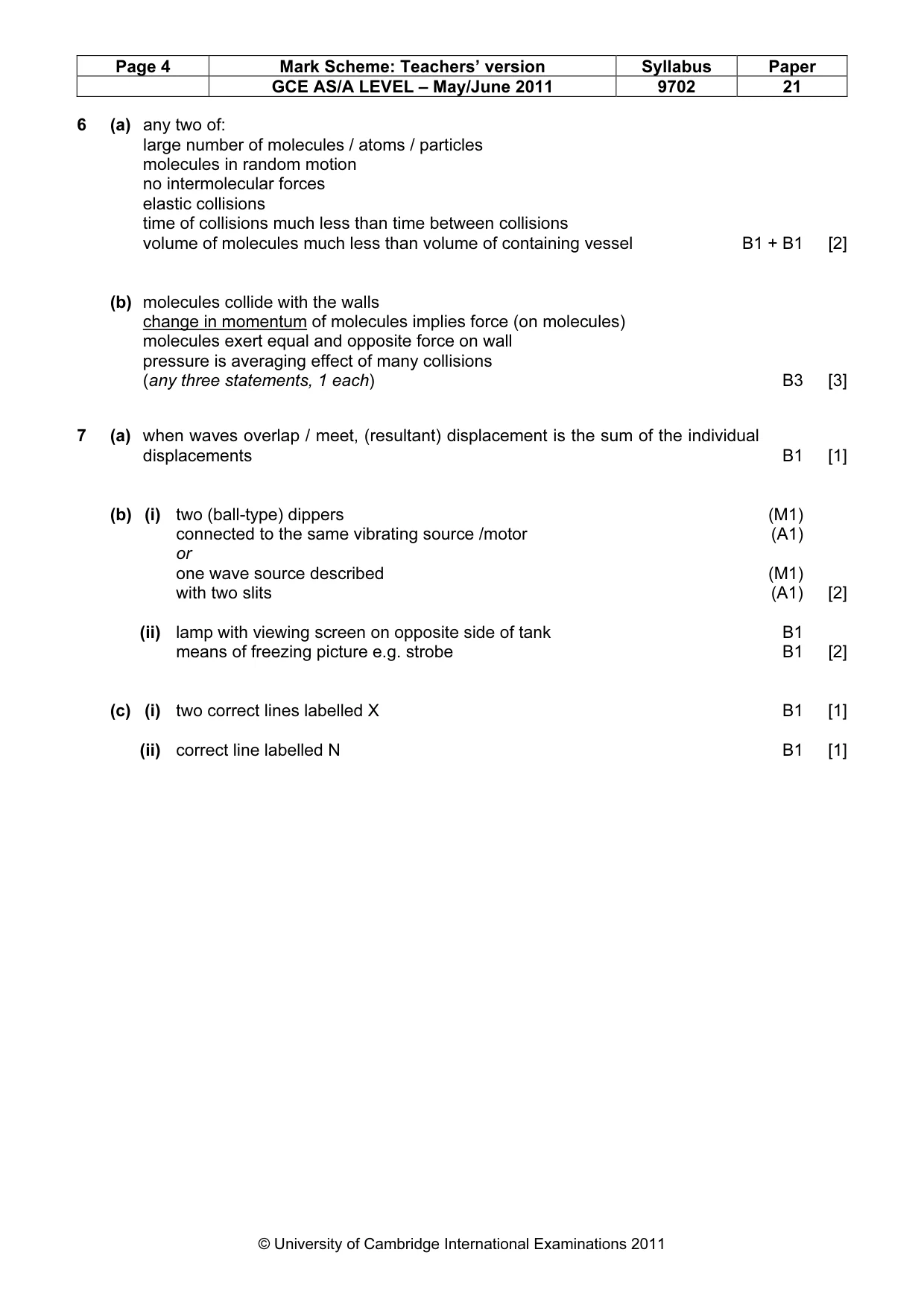
Mark scheme: 6 (a) any two of: large number of molecules / atoms / particles molecules in random motion no intermolecular forces elastic collisions time of collisions much less than time between collisions volume of molecules much less than volume of containing vessel B1 + B1 [2] (b) molecules collide with the walls change in momentum of molecules implies force (on molecules) molecules exert equal and opposite force on wall pressure is averaging effect of many collisions (any three statements, 1 each) B3 [3]
Q7 · Explain the term interference
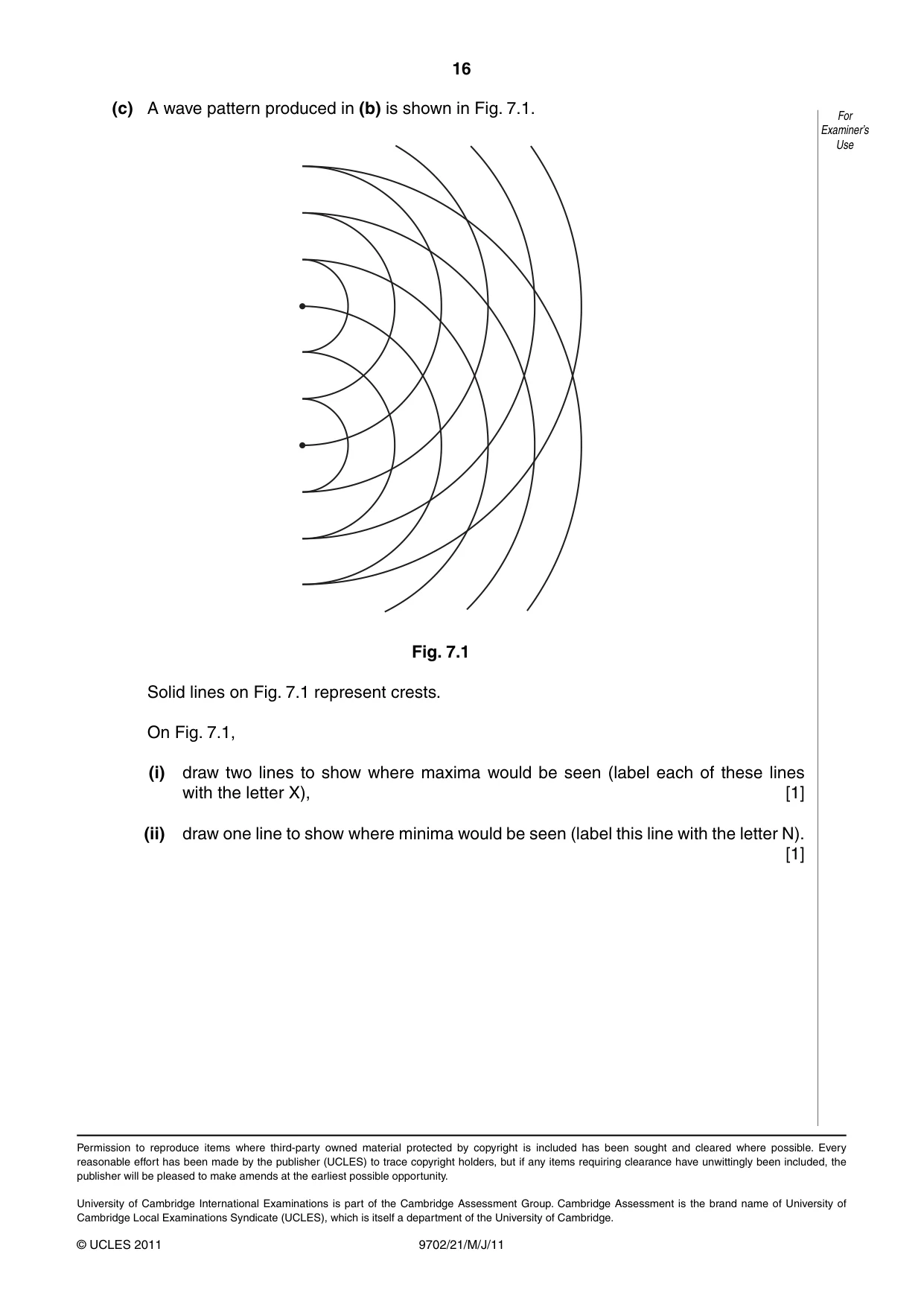
7 (a) Explain the term interference. For Examiner’s .......................................................................................................................................... Use .......................................................................................................................................... ..................................................................................................................................... [1] (b) A ripple tank is used to demonstrate interference between water waves. Describe (i) the apparatus used to produce two sources of coherent waves that have circular wavefronts, .................................................................................................................................. .................................................................................................................................. .................................................................................................................................. ............................................................................................................................. [2] (ii) how the pattern of interfering waves may be observed. .................................................................................................................................. .................................................................................................................................. .................................................................................................................................. ............................................................................................................................. [2] (c) A wave pattern produced in (b) is shown in Fig. 7.1. For Examiner’s Use Fig. 7.1 Solid lines on Fig. 7.1 represent crests. On Fig. 7.1, (i) draw two lines to show where maxima would be seen (label each of these lines with the letter X), [1] (ii) draw one line to show where minima would be seen (label this line with the letter N). [1]
Mark scheme: 7 (a) when waves overlap / meet, (resultant) displacement is the sum of the individual displacements B1 [1] (b) (i) two (ball-type) dippers (M1) connected to the same vibrating source /motor (A1) or one wave source described (M1) with two slits (A1) [2] (ii) lamp with viewing screen on opposite side of tank B1 means of freezing picture e.g. strobe B1 [2] (c) (i) two correct lines labelled X B1 [1] (ii) correct line labelled N B1 [1]
What was in this paper
The subtopics covered by these 7 questions, and how many questions each got. Open one in a new tab to see every Cambridge question on it.
What you needed in this session
Cambridge’s own grade thresholds for 2011 May/June, Paper 2 · Variant 1. A higher threshold means an easier paper — the bar moves with how the cohort did.