Cambridge IGCSE Physics 0625 — 2021 Oct/Nov Paper 5 · Variant 2
0625/52/O/N/21 · 4 questions · 40 marks · ≈45 min
The question paper and its mark scheme, free to read here and free to download. This is Cambridge’s own paper, exactly as it was sat.
Question paper12 pages
Mark scheme10 pages
Answers below. Sit the paper first if you are practising.
Questions as text
Q1 · In this experiment, you will determine the density of a block of wood
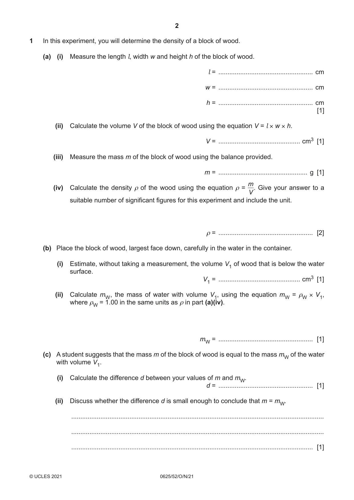
1 In this experiment, you will determine the density of a block of wood. (a) (i) Measure the length l, width w and height h of the block of wood. l = .................................................... cm w = .................................................... cm h = .................................................... cm [1] (ii) Calculate the volume V of the block of wood using the equation V = l × w × h. V = ............................................. cm3 [1] (iii) Measure the mass m of the block of wood using the balance provided. m = ................................................. g [1] m (iv) Calculate the density ρ of the wood using the equation ρ = V. Give your answer to a suitable number of significant figures for this experiment and include the unit. ρ = .................................................... [2] (b) Place the block of wood, largest face down, carefully in the water in the container. (i) Estimate, without taking a measurement, the volume V1 of wood that is below the water surface. V1 = ............................................. cm3 [1] (ii) Calculate mW , the mass of water with volume V1, using the equation mW = ρW × V1, where ρW = 1.00 in the same units as ρ in part (a)(iv). mW = .................................................... [1] (c) A student suggests that the mass m of the block of wood is equal to the mass mW of the water with volume V1. (i) Calculate the difference d between your values of m and mW. d = .................................................... [1] (ii) Discuss whether the difference d is small enough to conclude that m = mW. ........................................................................................................................................... ........................................................................................................................................... ..................................................................................................................................... [1] (d) Another student wants to obtain a more accurate value for V1. He uses the method of floating the block of wood in water as described in (b). Suggest how the student could obtain a more accurate value by taking a measurement. You are not required to do this part of the experiment. ................................................................................................................................................... ................................................................................................................................................... ............................................................................................................................................. [2] [Total: 11]
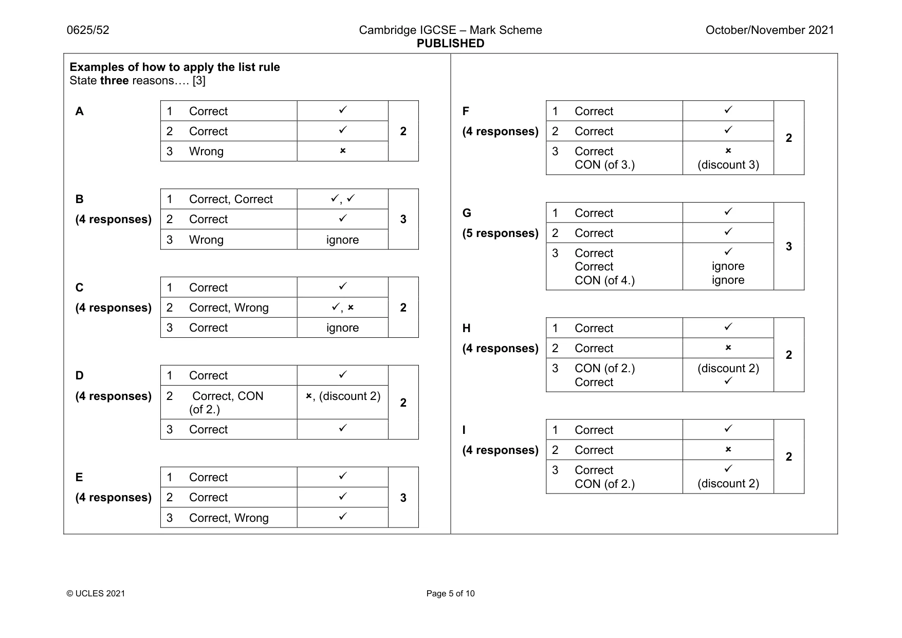
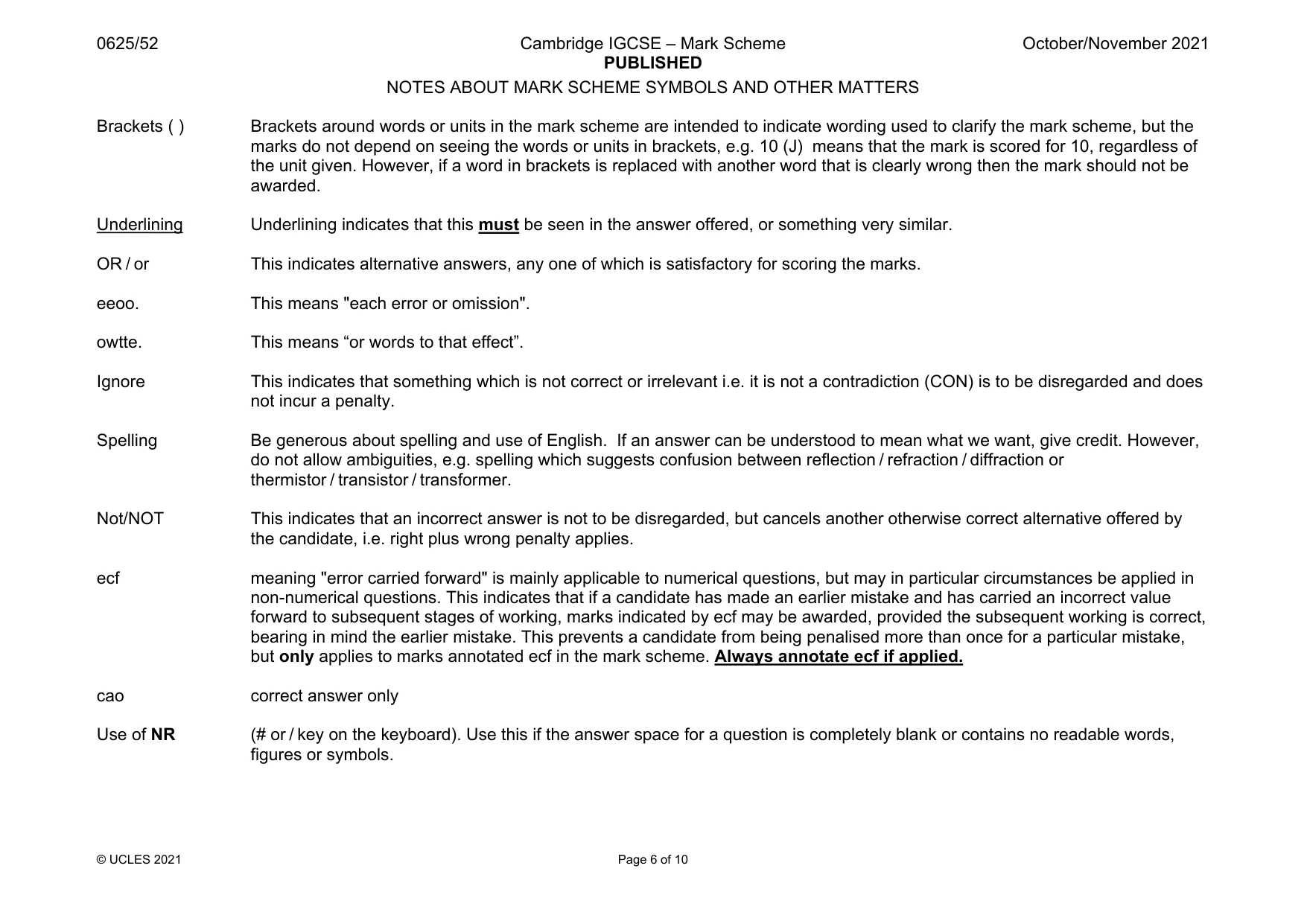
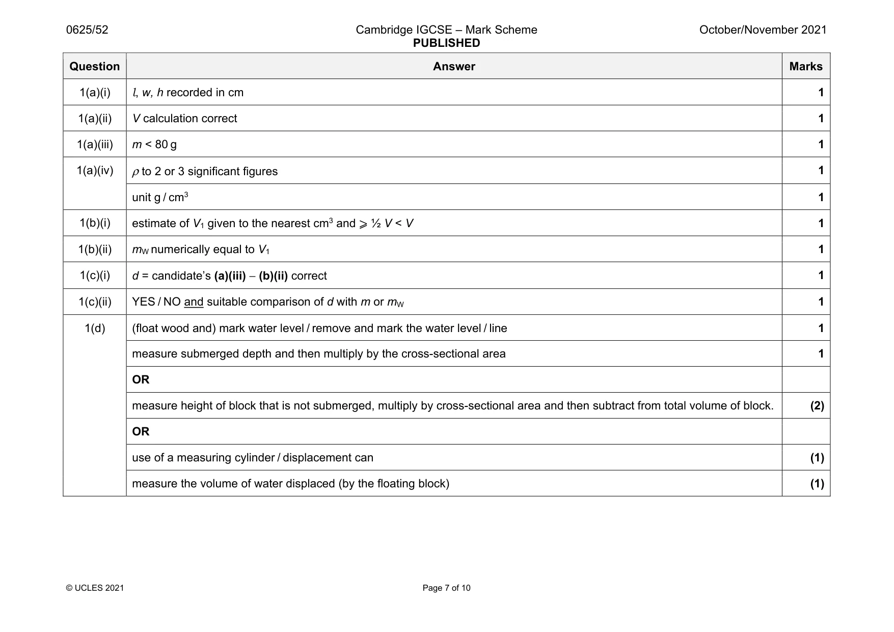
Mark scheme: 1(a)(i) 1 1(a)(ii) V calculation correct 1 1(a)(iii) m < 80 g 1 1(a)(iv) ρ to 2 or 3 significant figures 1 unit g / cm3 1 1(b)(i) estimate of V1 given to the nearest cm3 and ⩾ ½ V < V 1 1(b)(ii) mW numerically equal to V1 1 1(c)(i) d = candidate’s (a)(iii) − (b)(ii) correct 1 1(c)(ii) YES / NO and suitable comparison of d with m or mW 1 1(d) (float wood and) mark water level / remove and mark the water level / line 1 measure submerged depth and then multiply by the cross-sectional area 1 OR measure height of block that is not submerged, multiply by cross-sectional area and then subtract from total volume of block. (2) OR use of a measuring cylinder / displacement can (1) measure the volume of water displaced (by the floating block) (1)
Q2 · In this experiment, you will investigate the resistances of a resistor and a lamp
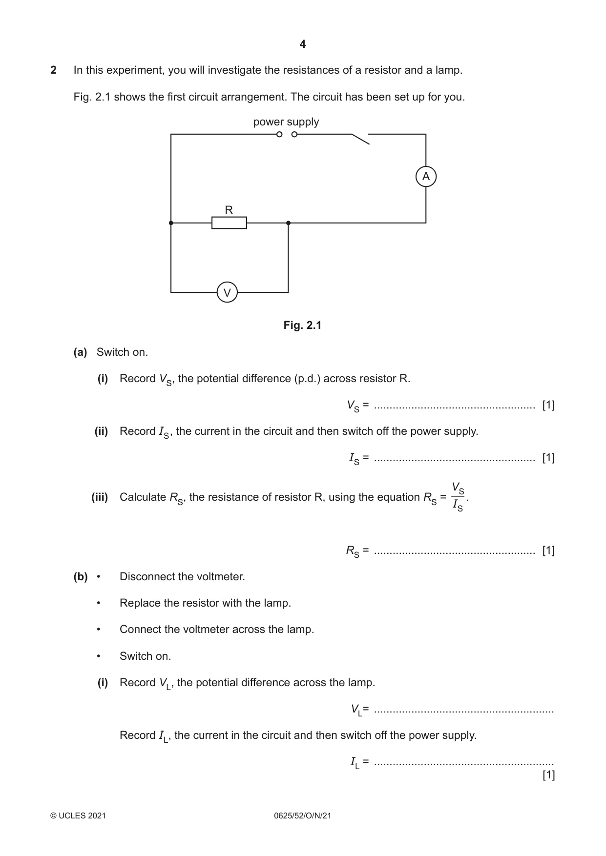
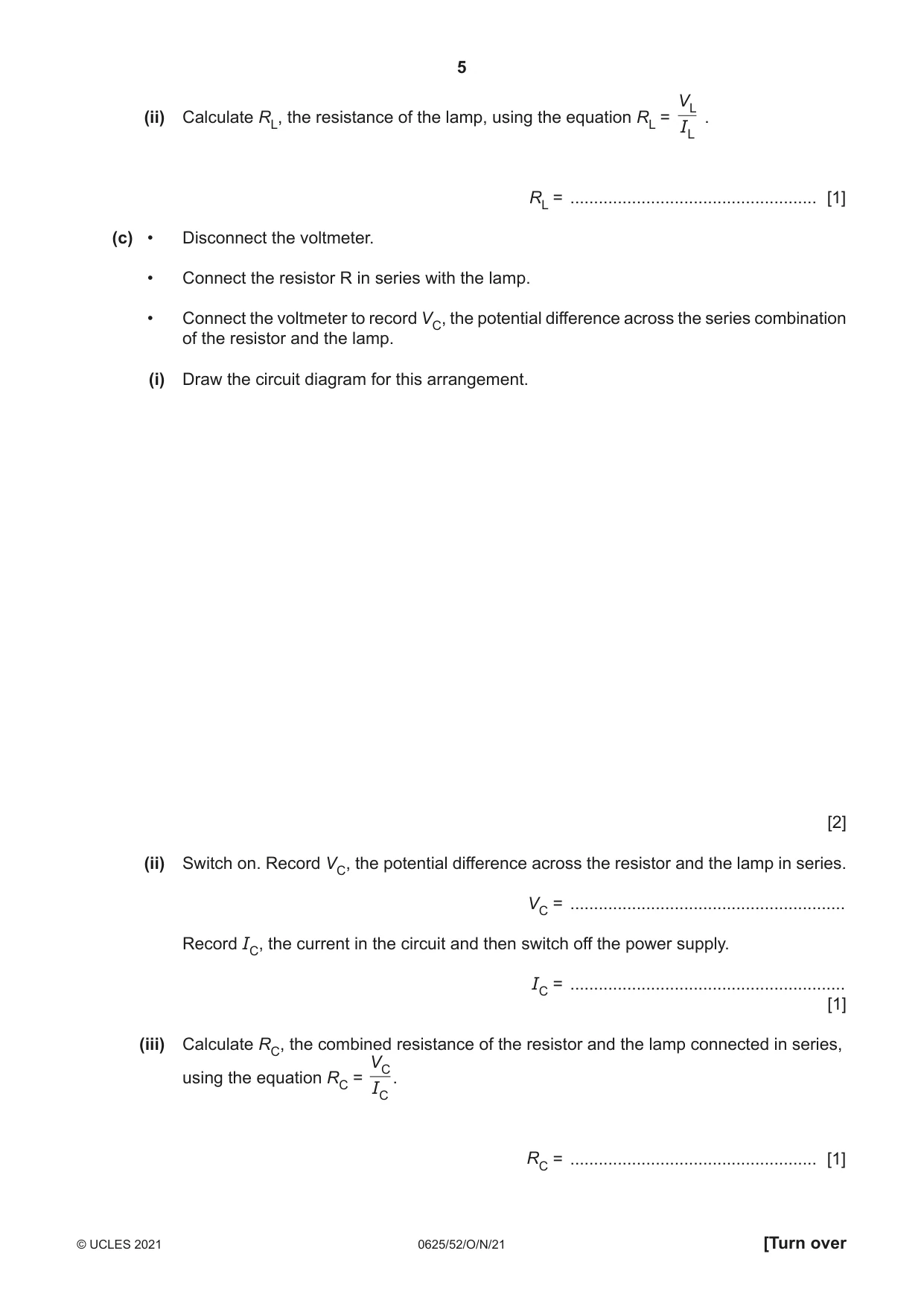
2 In this experiment, you will investigate the resistances of a resistor and a lamp. Fig. 2.1 shows the first circuit arrangement. The circuit has been set up for you. power supply A R V Fig. 2.1 (a) Switch on. (i) Record VS, the potential difference (p.d.) across resistor R. VS = .................................................... [1] (ii) Record IS , the current in the circuit and then switch off the power supply. IS = .................................................... [1] VS (iii) Calculate RS, the resistance of resistor R, using the equation RS = . IS RS = .................................................... [1] (b) • Disconnect the voltmeter. • Replace the resistor with the lamp. • Connect the voltmeter across the lamp. • Switch on. (i) Record VL, the potential difference across the lamp. VL= .......................................................... Record IL, the current in the circuit and then switch off the power supply. IL = .......................................................... [1] VL (ii) Calculate RL, the resistance of the lamp, using the equation RL = . IL RL = .................................................... [1] (c) • Disconnect the voltmeter. • Connect the resistor R in series with the lamp. • Connect the voltmeter to record VC, the potential difference across the series combination of the resistor and the lamp. (i) Draw the circuit diagram for this arrangement. [2] (ii) Switch on. Record VC, the potential difference across the resistor and the lamp in series. VC = .......................................................... Record IC, the current in the circuit and then switch off the power supply. IC = .......................................................... [1] (iii) Calculate RC, the combined resistance of the resistor and the lamp connected in series, VC using the equation RC = . IC RC = .................................................... [1] (d) State and explain briefly whether your results show that RS + RL = RC within the limits of experimental accuracy. statement .................................................................................................................................. explanation ............................................................................................................................... ................................................................................................................................................... [2] [Total: 11]
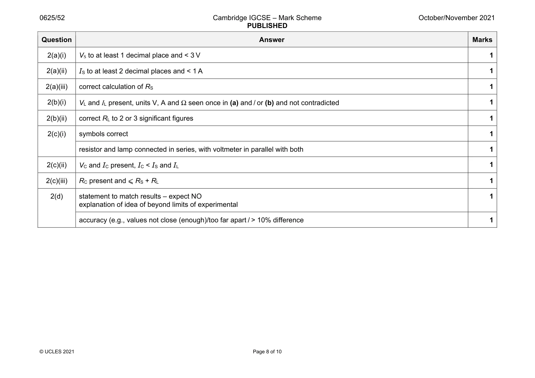
Mark scheme: 2(a)(i) VS to at least 1 decimal place and < 3 V 1 2(a)(ii) IS to at least 2 decimal places and < 1 A 1 2(a)(iii) correct calculation of RS 1 2(b)(i) VL and IL present, units V, A and Ω seen once in (a) and / or (b) and not contradicted 1 2(b)(ii) correct RL to 2 or 3 significant figures 1 2(c)(i) symbols correct 1 resistor and lamp connected in series, with voltmeter in parallel with both 1 2(c)(ii) VC and IC present, IC < IS and IL 1 2(c)(iii) RC present and ⩽ RS + RL 1 2(d) statement to match results – expect NO explanation of idea of beyond limits of experimental 1 accuracy (e.g., values not close (enough)/too far apart / > 10% difference 1
Q3 · In this experiment, you will investigate the image produced by a lens
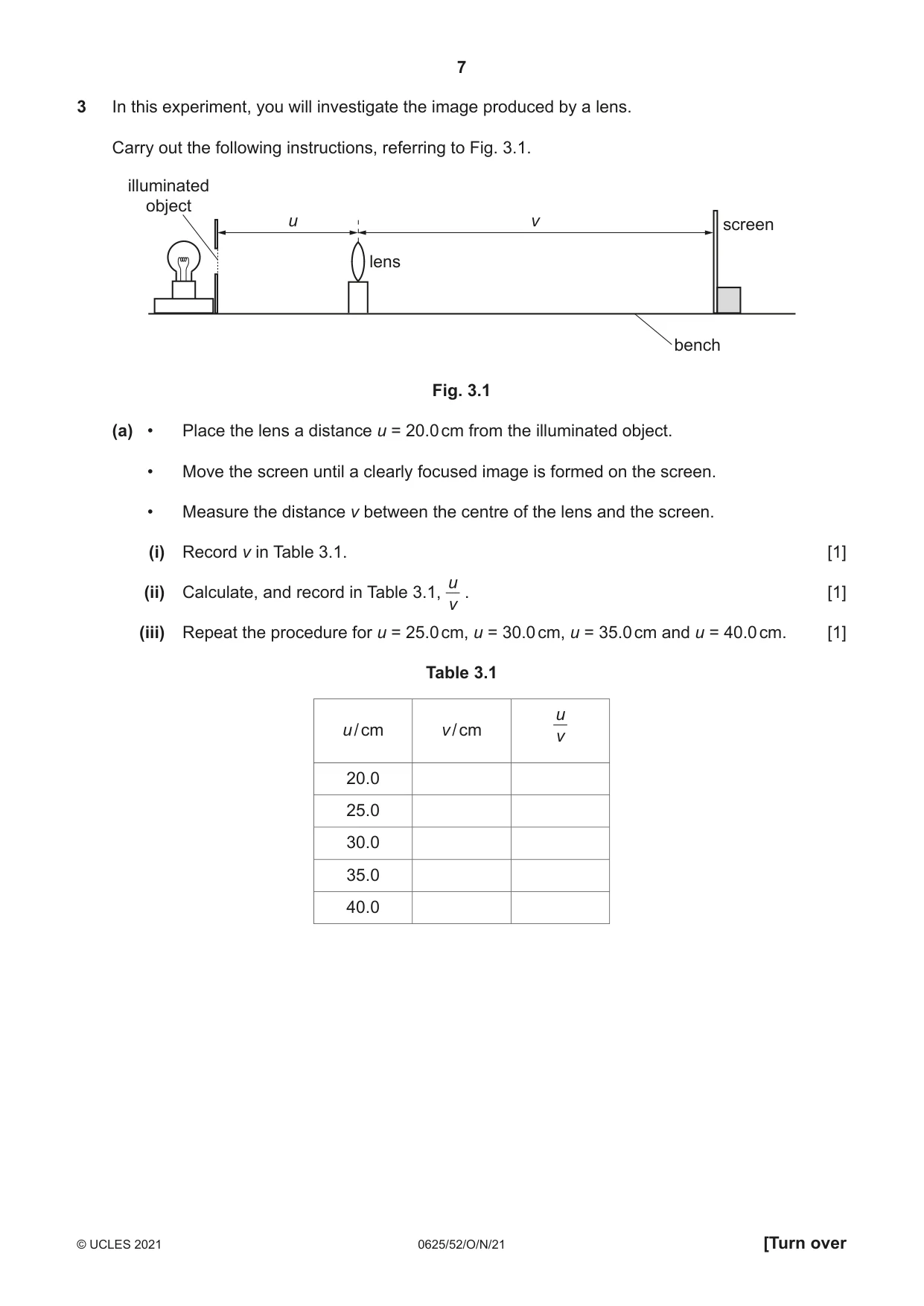
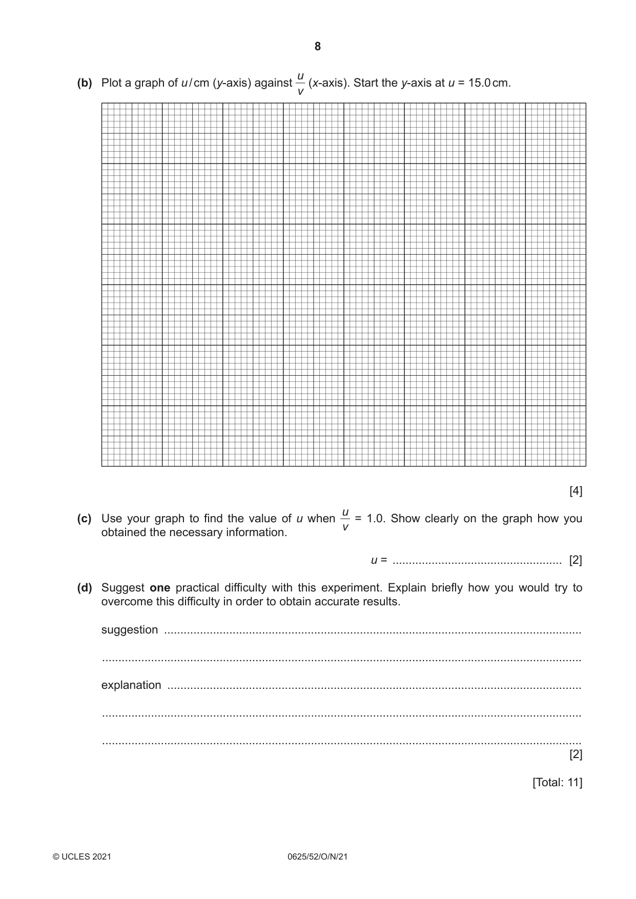
3 In this experiment, you will investigate the image produced by a lens. Carry out the following instructions, referring to Fig. 3.1. illuminated object u v screen lens bench Fig. 3.1 (a) • Place the lens a distance u = 20.0 cm from the illuminated object. • Move the screen until a clearly focused image is formed on the screen. • Measure the distance v between the centre of the lens and the screen. (i) Record v in Table 3.1. [1] u (ii) Calculate, and record in Table 3.1, . [1] v (iii) Repeat the procedure for u = 25.0 cm, u = 30.0 cm, u = 35.0 cm and u = 40.0 cm. [1] Table 3.1 u u / cm v / cm v 20.0 25.0 30.0 35.0 40.0 u(b) Plot a graph of u / cm (y-axis) against (x-axis). Start the y-axis at u = 15.0 cm. v [4] u(c) Use your graph to find the value of u when = 1.0. Show clearly on the graph how you v obtained the necessary information. u = .................................................... [2] (d) Suggest one practical difficulty with this experiment. Explain briefly how you would try to overcome this difficulty in order to obtain accurate results. suggestion ................................................................................................................................ ................................................................................................................................................... explanation ............................................................................................................................... ................................................................................................................................................... ................................................................................................................................................... [2] [Total: 11]
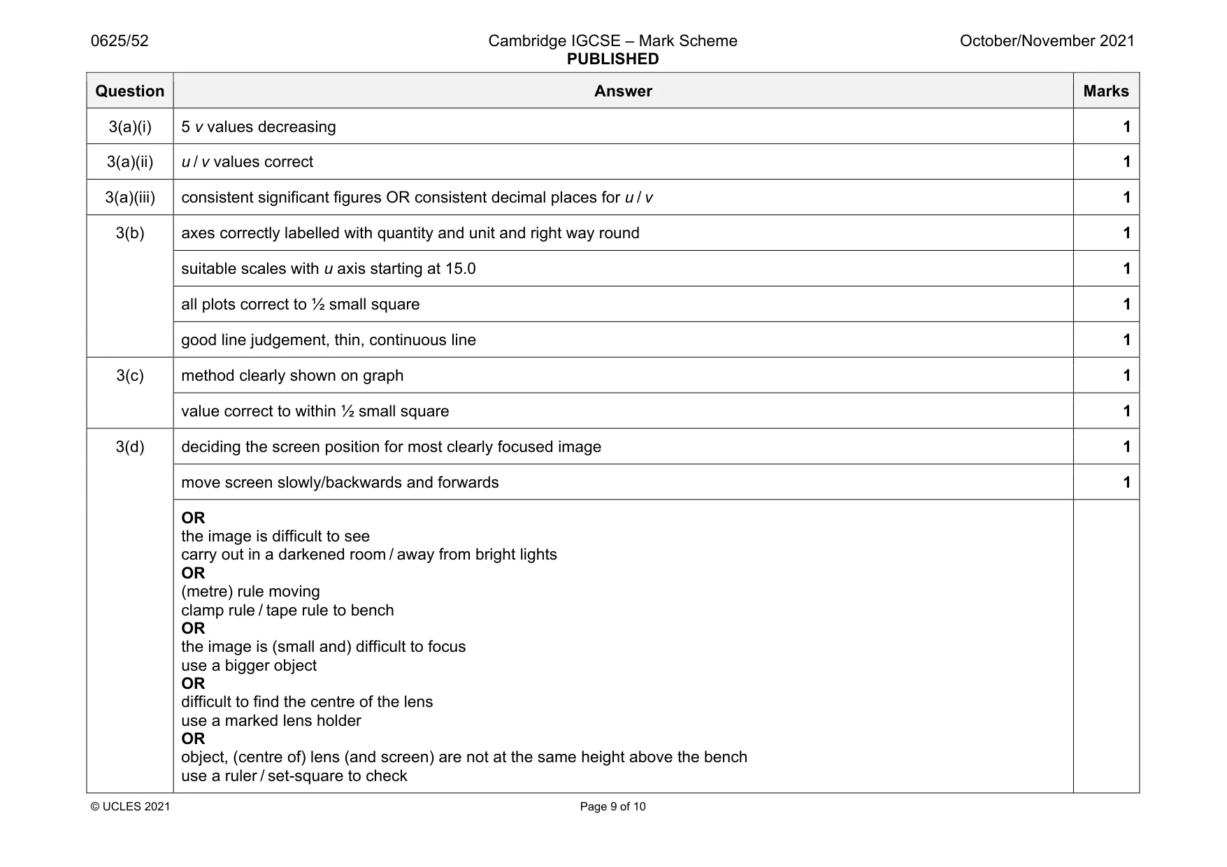
Mark scheme: 3(a)(i) 5 v values decreasing 1 3(a)(ii) u / v values correct 1 3(a)(iii) consistent significant figures OR consistent decimal places for u / v 1 3(b) axes correctly labelled with quantity and unit and right way round 1 suitable scales with u axis starting at 15.0 1 all plots correct to ½ small square 1 good line judgement, thin, continuous line 1 3(c) method clearly shown on graph 1 value correct to within ½ small square 1 3(d) deciding the screen position for most clearly focused image 1 move screen slowly/backwards and forwards 1 OR the image is difficult to see carry out in a darkened room / away from bright lights OR (metre) rule moving clamp rule / tape rule to bench OR the image is (small and) difficult to focus use a bigger object OR difficult to find the centre of the lens use a marked lens holder OR object, (centre of) lens (and screen) are not at the same height above the bench use a ruler / set-square to check
Q4 · A student investigates the strengths of wires made from different metals by measuring the…
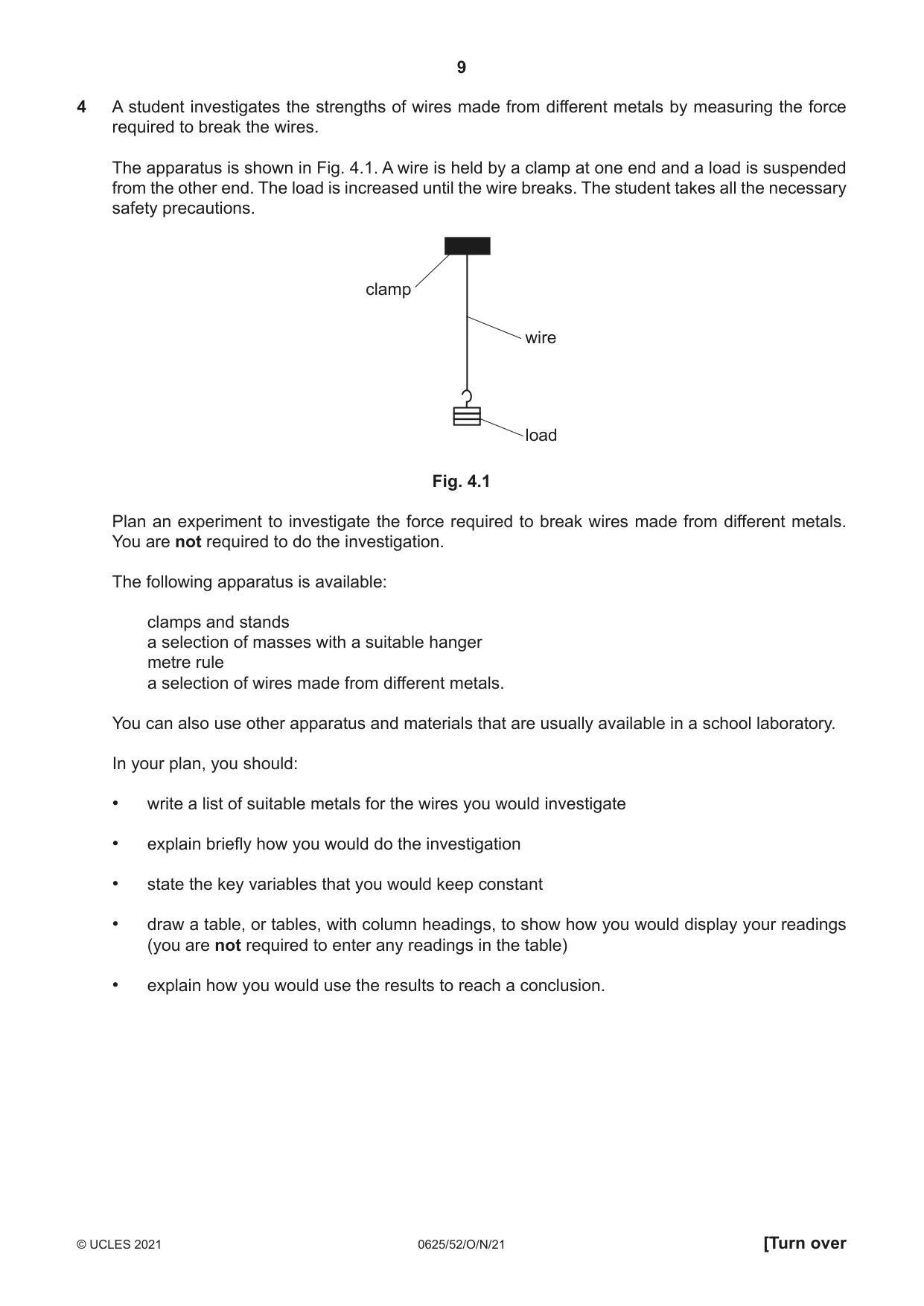
4 A student investigates the strengths of wires made from different metals by measuring the force required to break the wires. The apparatus is shown in Fig. 4.1. A wire is held by a clamp at one end and a load is suspended from the other end. The load is increased until the wire breaks. The student takes all the necessary safety precautions. clamp wire load Fig. 4.1 Plan an experiment to investigate the force required to break wires made from different metals. You are not required to do the investigation. The following apparatus is available: clamps and stands a selection of masses with a suitable hanger metre rule a selection of wires made from different metals. You can also use other apparatus and materials that are usually available in a school laboratory. In your plan, you should: • write a list of suitable metals for the wires you would investigate • explain briefly how you would do the investigation • state the key variables that you would keep constant • draw a table, or tables, with column headings, to show how you would display your readings (you are not required to enter any readings in the table) • explain how you would use the results to reach a conclusion. You may add to the diagram if it helps your explanation. You are not required to write about the safety precautions that the student should take. .......................................................................................................................................................... .......................................................................................................................................................... .......................................................................................................................................................... .......................................................................................................................................................... .......................................................................................................................................................... .......................................................................................................................................................... .......................................................................................................................................................... .......................................................................................................................................................... .......................................................................................................................................................... .......................................................................................................................................................... .......................................................................................................................................................... .......................................................................................................................................................... .......................................................................................................................................................... .......................................................................................................................................................... .......................................................................................................................................................... .......................................................................................................................................................... .......................................................................................................................................................... .......................................................................................................................................................... .......................................................................................................................................................... .................................................................................................................................................... [7]
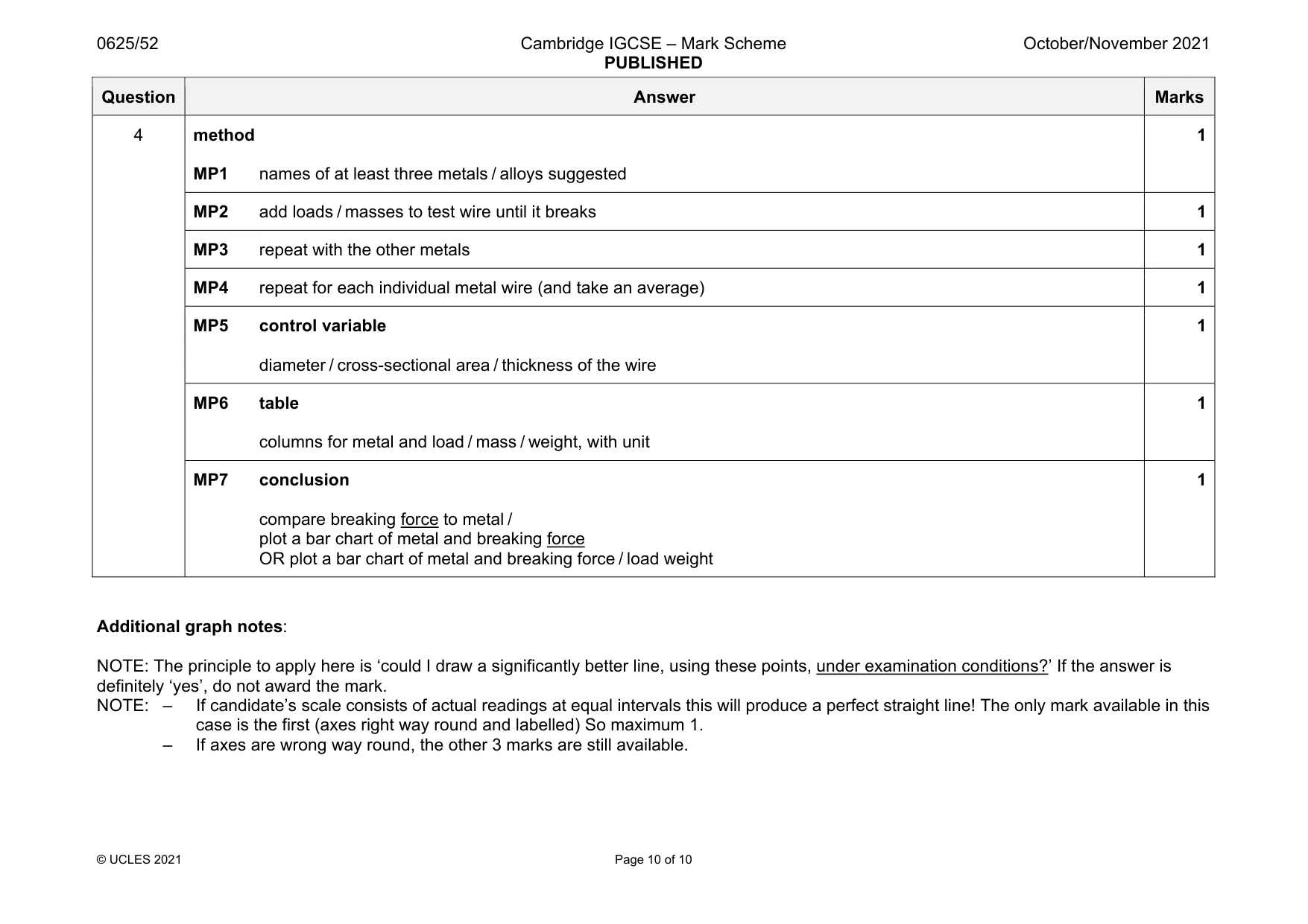
Mark scheme: 4 method MP1 names of at least three metals / alloys suggested 1 MP2 add loads / masses to test wire until it breaks 1 MP3 repeat with the other metals 1 MP4 repeat for each individual metal wire (and take an average) 1 MP5 control variable diameter / cross-sectional area / thickness of the wire 1 MP6 table columns for metal and load / mass / weight, with unit 1 MP7 conclusion compare breaking force to metal / plot a bar chart of metal and breaking force OR plot a bar chart of metal and breaking force / load weight 1 Additional graph notes: NOTE: The principle to apply here is ‘could I draw a significantly better line, using these points, under examination conditions?’ If the answer is definitely ‘yes’, do not award the mark. NOTE: – If candidate’s scale consists of actual readings at equal intervals this will produce a perfect straight line! The only mark available in this case is the first (axes right way round and labelled) So maximum 1. – If axes are wrong way round, the other 3 marks are still available.
What was in this paper
The subtopics covered by these 4 questions, and how many questions each got. Open one in a new tab to see every Cambridge question on it.
What you needed in this session
Cambridge’s own grade thresholds for 2021 Oct/Nov, Paper 5 · Variant 2. A higher threshold means an easier paper — the bar moves with how the cohort did.