Cambridge IGCSE Physics 0625 — 2015 Oct/Nov Paper 5 · Variant 2
0625/52/O/N/15 · 4 questions · 40 marks · ≈45 min
The question paper and its mark scheme, free to read here and free to download. This is Cambridge’s own paper, exactly as it was sat.
Question paper12 pages
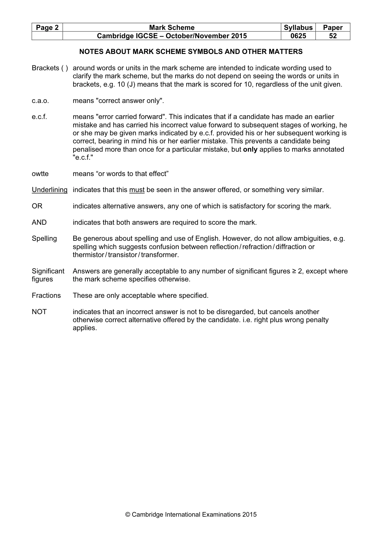
Mark scheme4 pages
Answers below. Sit the paper first if you are practising.
Questions as text
Q1 · In this experiment, you will investigate the masses of two loads, P and Q
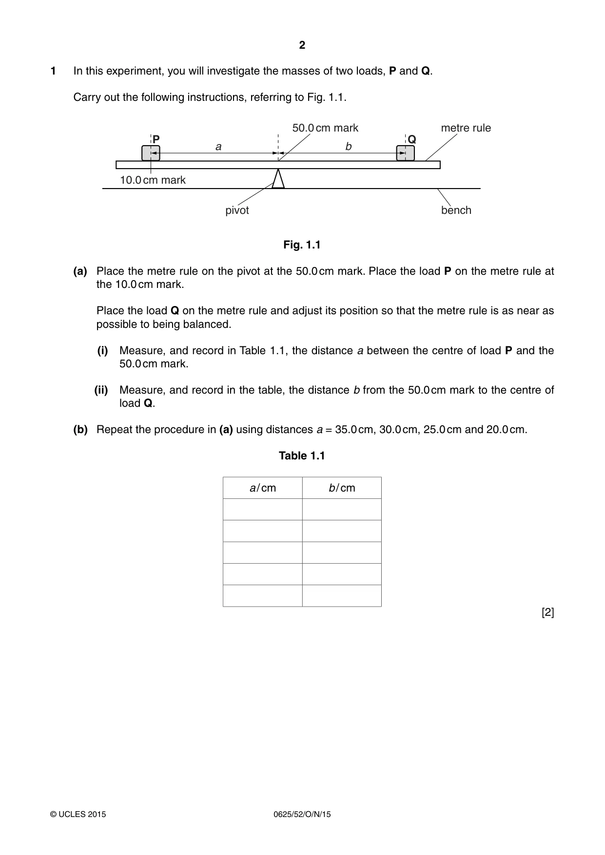
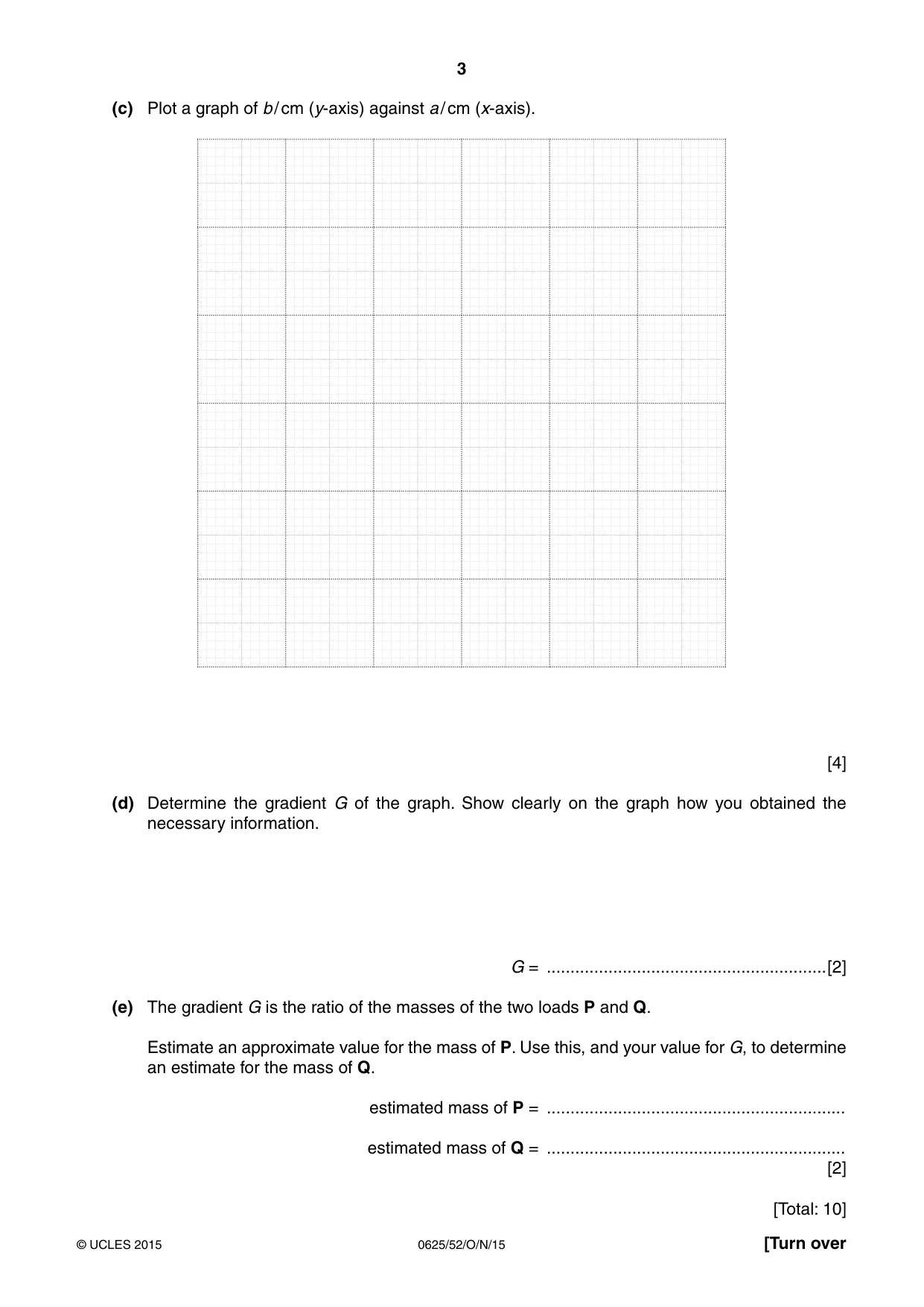
1 In this experiment, you will investigate the masses of two loads, P and Q. Carry out the following instructions, referring to Fig. 1.1. 50.0 cm mark metre rule P Q a b 10.0 cm mark pivot bench Fig. 1.1 (a) Place the metre rule on the pivot at the 50.0 cm mark. Place the load P on the metre rule at the 10.0 cm mark. Place the load Q on the metre rule and adjust its position so that the metre rule is as near as possible to being balanced. (i) Measure, and record in Table 1.1, the distance a between the centre of load P and the 50.0 cm mark. (ii) Measure, and record in the table, the distance b from the 50.0 cm mark to the centre of load Q. (b) Repeat the procedure in (a) using distances a = 35.0 cm, 30.0 cm, 25.0 cm and 20.0 cm. Table 1.1 a / cm b / cm [2] (c) Plot a graph of b / cm (y-axis) against a / cm (x-axis). [4] (d) Determine the gradient G of the graph. Show clearly on the graph how you obtained the necessary information. G = ...........................................................[2] (e) The gradient G is the ratio of the masses of the two loads P and Q. Estimate an approximate value for the mass of P. Use this, and your value for G, to determine an estimate for the mass of Q. estimated mass of P = ............................................................... estimated mass of Q = ............................................................... [2] [Total: 10]
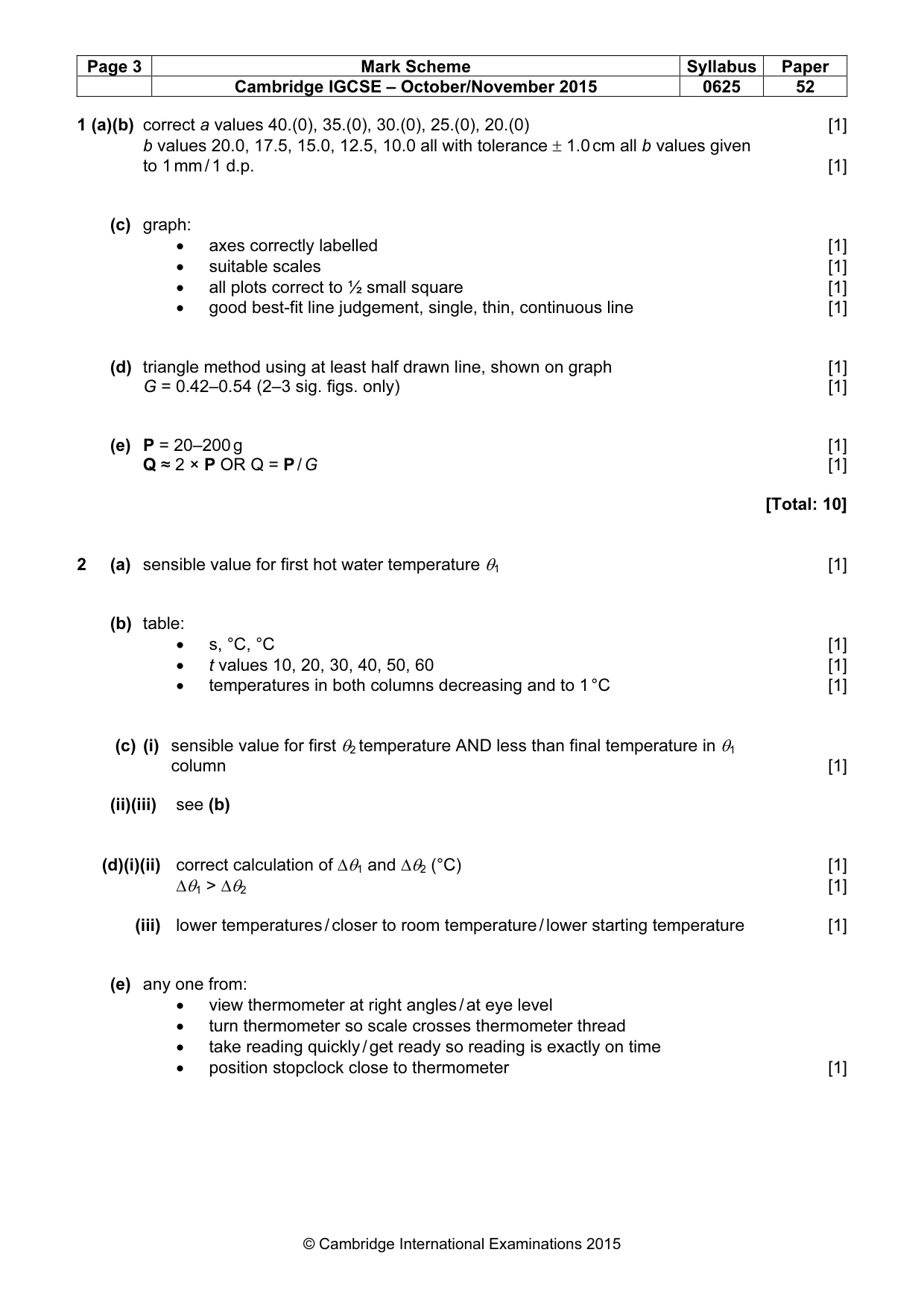
Mark scheme: 1 (a)(b) correct a values 40.(0), 35.(0), 30.(0), 25.(0), 20.(0) [1] b values 20.0, 17.5, 15.0, 12.5, 10.0 all with tolerance ± 1.0 cm all b values given to 1 mm / 1 d.p. [1] (c) graph: • axes correctly labelled [1] • suitable scales [1] • all plots correct to ½ small square [1] • good best-fit line judgement, single, thin, continuous line [1] (d) triangle method using at least half drawn line, shown on graph [1] G = 0.42–0.54 (2–3 sig. figs. only) [1] (e) P = 20–200 g [1] Q ≈ 2 × P OR Q = P / G [1] [Total: 10]
Q2 · In this experiment, you will investigate the cooling of a thermometer bulb
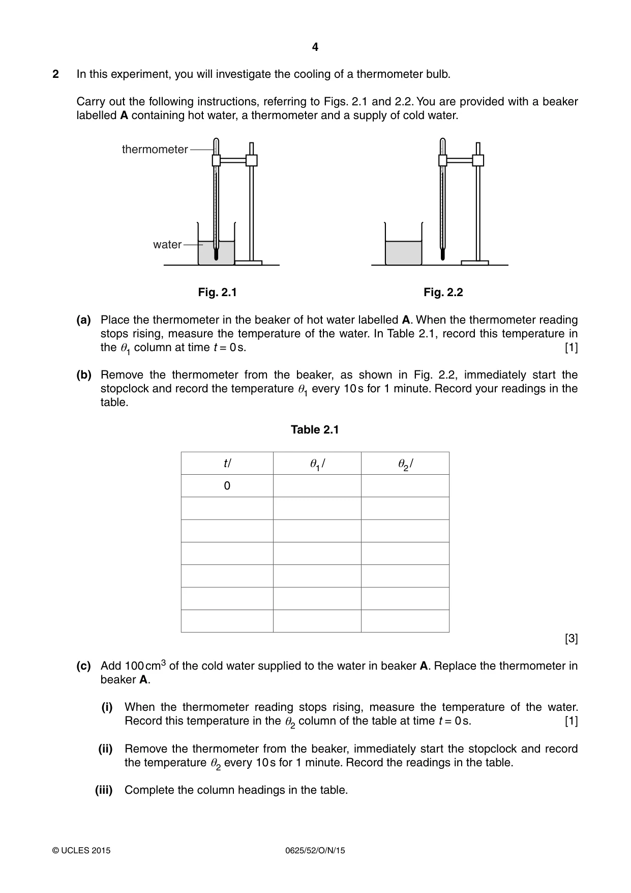
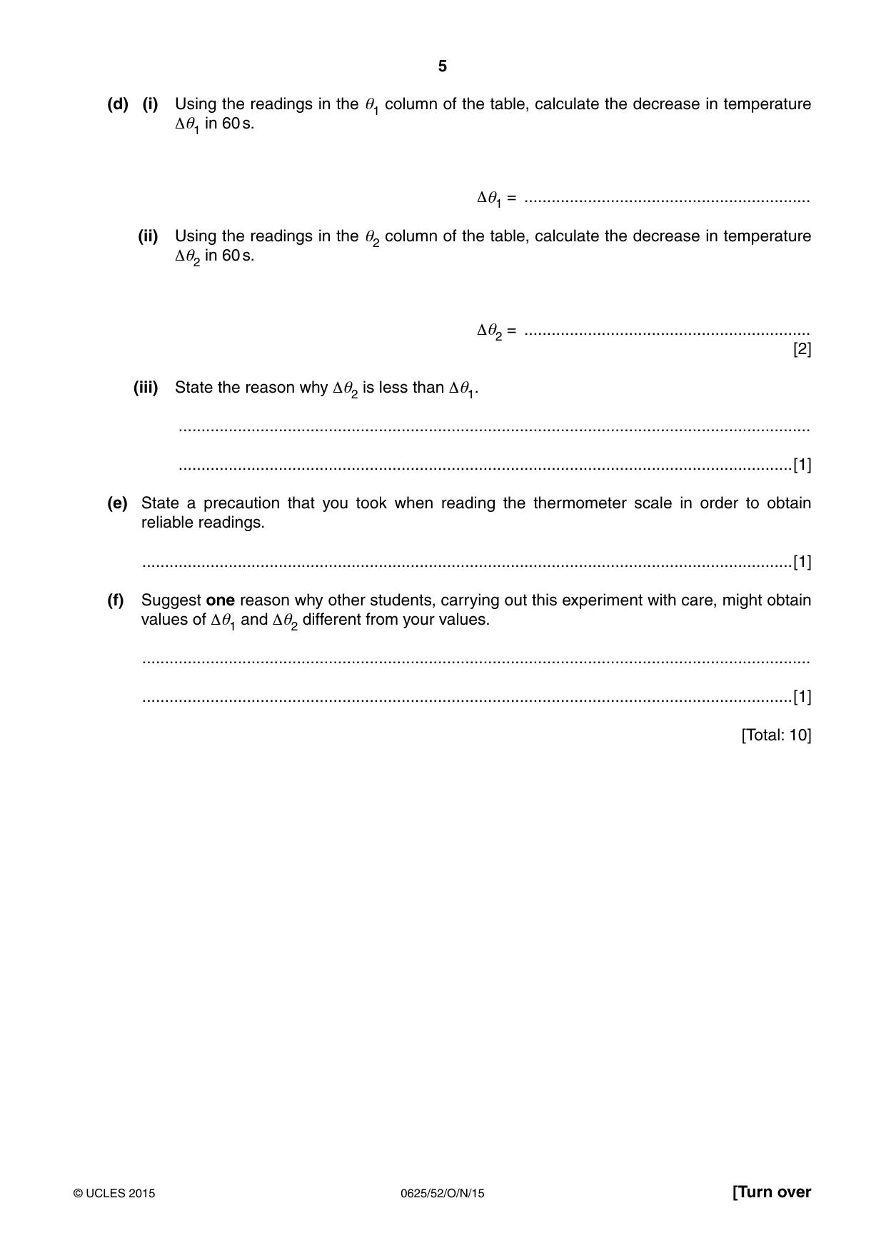
2 In this experiment, you will investigate the cooling of a thermometer bulb. Carry out the following instructions, referring to Figs. 2.1 and 2.2. You are provided with a beaker labelled A containing hot water, a thermometer and a supply of cold water. thermometer water Fig. 2.1 Fig. 2.2 (a) Place the thermometer in the beaker of hot water labelled A. When the thermometer reading stops rising, measure the temperature of the water. In Table 2.1, record this temperature in the θ1 column at time t = 0 s. [1] (b) Remove the thermometer from the beaker, as shown in Fig. 2.2, immediately start the stopclock and record the temperature θ1 every 10 s for 1 minute. Record your readings in the table. Table 2.1 t / θ1 / θ2 / 0 [3] (c) Add 100 cm3 of the cold water supplied to the water in beaker A. Replace the thermometer in beaker A. (i) When the thermometer reading stops rising, measure the temperature of the water. Record this temperature in the θ2 column of the table at time t = 0 s. [1] (ii) Remove the thermometer from the beaker, immediately start the stopclock and record the temperature θ2 every 10 s for 1 minute. Record the readings in the table. (iii) Complete the column headings in the table. (d) (i) Using the readings in the θ1 column of the table, calculate the decrease in temperature Δθ1 in 60 s. Δθ1 = ............................................................... (ii) Using the readings in the θ2 column of the table, calculate the decrease in temperature Δθ2 in 60 s. Δθ2 = ............................................................... [2] (iii) State the reason why Δθ2 is less than Δθ1. ........................................................................................................................................... .......................................................................................................................................[1] (e) State a precaution that you took when reading the thermometer scale in order to obtain reliable readings. ...............................................................................................................................................[1] (f) Suggest one reason why other students, carrying out this experiment with care, might obtain values of Δθ1 and Δθ2 different from your values. ................................................................................................................................................... ...............................................................................................................................................[1] [Total: 10]
Mark scheme: 2 (a) sensible value for first hot water temperature θ1 [1] (b) table: • s, °C, °C [1] • t values 10, 20, 30, 40, 50, 60 [1] • temperatures in both columns decreasing and to 1 °C [1] (c) (i) sensible value for first θ2 temperature AND less than final temperature in θ1 column [1] (ii)(iii) see (b) (d)(i)(ii) correct calculation of ∆θ1 and ∆θ2 (°C) [1] ∆θ1 > ∆θ2 [1] (iii) lower temperatures / closer to room temperature / lower starting temperature [1] (e) any one from: • view thermometer at right angles / at eye level • turn thermometer so scale crosses thermometer thread • take reading quickly / get ready so reading is exactly on time • position stopclock close to thermometer [1] (f) any one from: • room temperature / other environmental factor • volume / mass / quantity / amount of hot water • initial temperature of hot water • initial temperature of cold water [1] [Total: 10]
Q3 · In this experiment, you will investigate the combined resistance of resistors in series…
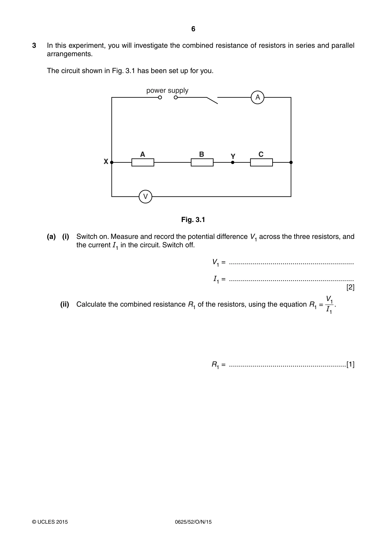
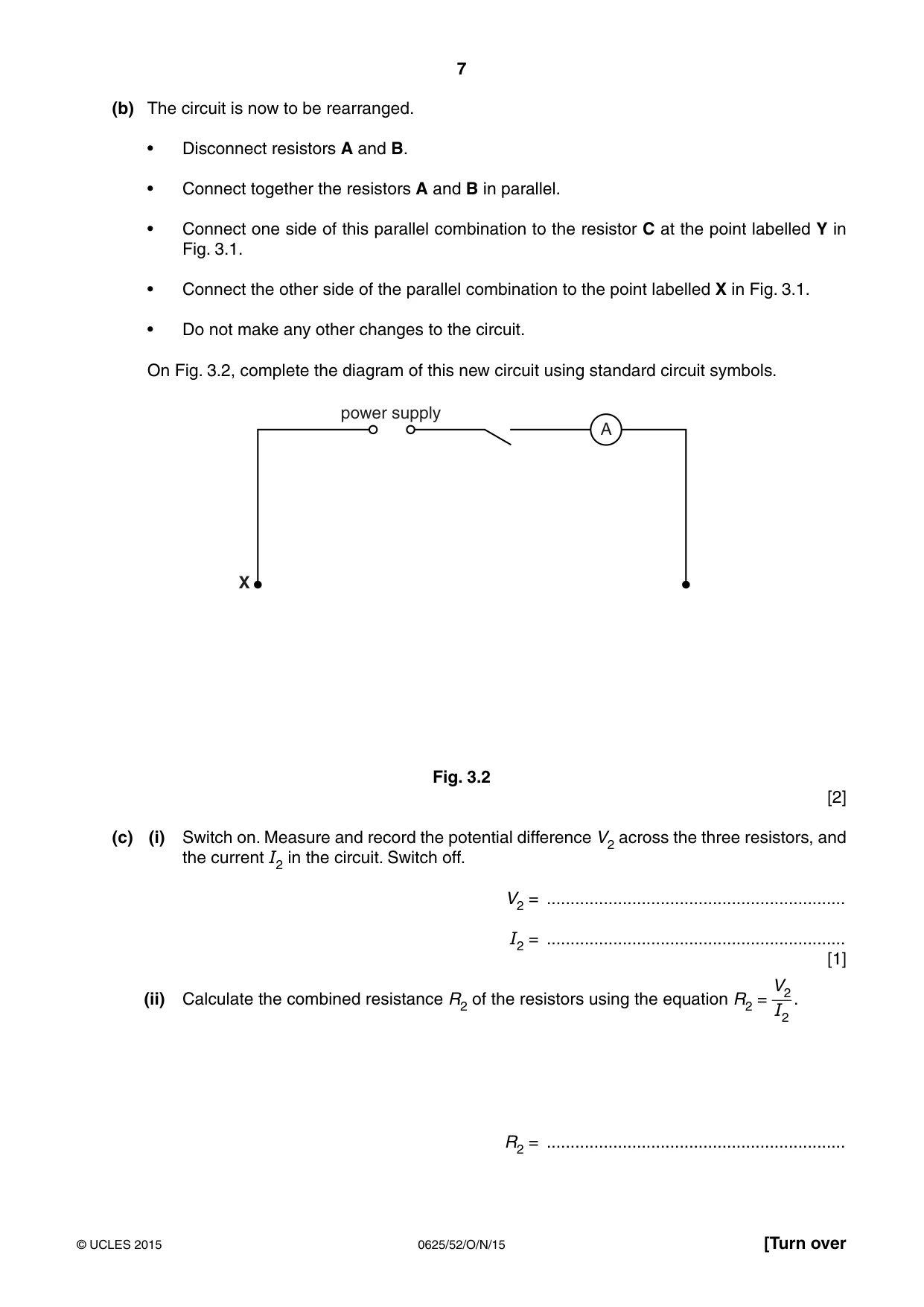
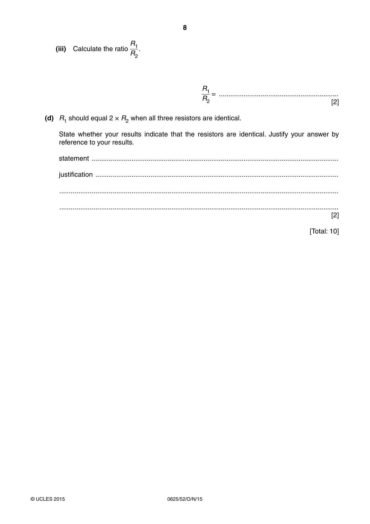
3 In this experiment, you will investigate the combined resistance of resistors in series and parallel arrangements. The circuit shown in Fig. 3.1 has been set up for you. power supply A A B C Y X V Fig. 3.1 (a) (i) Switch on. Measure and record the potential difference V1 across the three resistors, and the current I1 in the circuit. Switch off. V1 = ............................................................... I1 = ............................................................... [2] V1 (ii) Calculate the combined resistance R1 of the resistors, using the equation R1 = . I1 R1 = ...........................................................[1] (b) The circuit is now to be rearranged. • Disconnect resistors A and B. • Connect together the resistors A and B in parallel. • Connect one side of this parallel combination to the resistor C at the point labelled Y in Fig. 3.1. • Connect the other side of the parallel combination to the point labelled X in Fig. 3.1. • Do not make any other changes to the circuit. On Fig. 3.2, complete the diagram of this new circuit using standard circuit symbols. power supply A X Fig. 3.2 [2] (c) (i) Switch on. Measure and record the potential difference V2 across the three resistors, and the current I2 in the circuit. Switch off. V2 = ............................................................... I2 = ............................................................... [1] V2 (ii) Calculate the combined resistance R2 of the resistors using the equation R2 = . I2 R2 = ............................................................... R1 (iii) Calculate the ratio . R2 R1 = ............................................................... R2 [2] (d) R1 should equal 2 × R2 when all three resistors are identical. State whether your results indicate that the resistors are identical. Justify your answer by reference to your results. statement .................................................................................................................................. justification ................................................................................................................................ ................................................................................................................................................... ................................................................................................................................................... [2] [Total: 10]
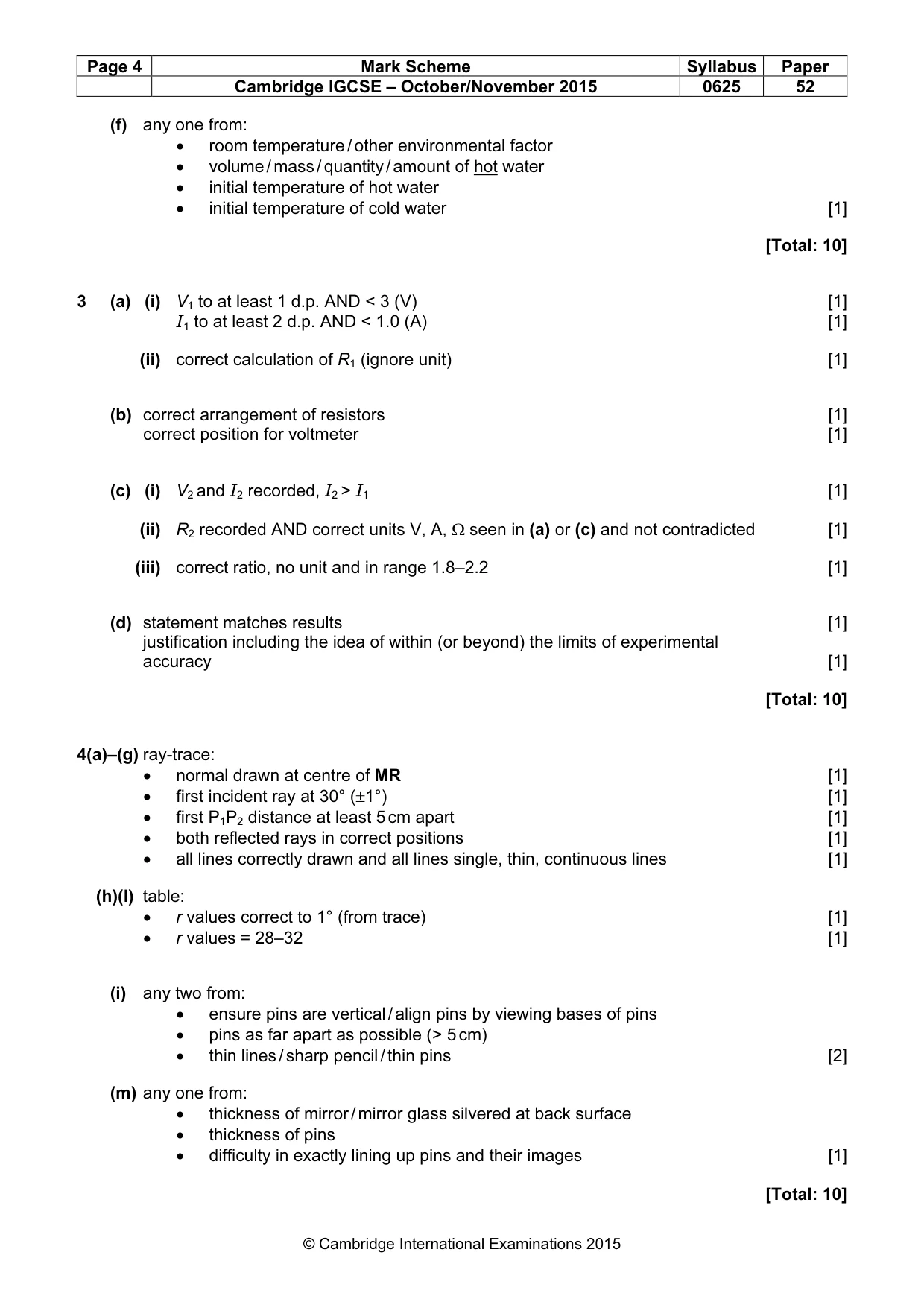
Mark scheme: 3 (a) (i) V1 to at least 1 d.p. AND < 3 (V) [1] I1 to at least 2 d.p. AND < 1.0 (A) [1] (ii) correct calculation of R1 (ignore unit) [1] (b) correct arrangement of resistors [1] correct position for voltmeter [1] (c) (i) V2 and I2 recorded, I2 > I1 [1] (ii) R2 recorded AND correct units V, A, Ω seen in (a) or (c) and not contradicted [1] (iii) correct ratio, no unit and in range 1.8–2.2 [1] (d) statement matches results [1] justification including the idea of within (or beyond) the limits of experimental accuracy [1] [Total: 10]
Q4 · In this experiment, you will investigate reflection using a plane mirror
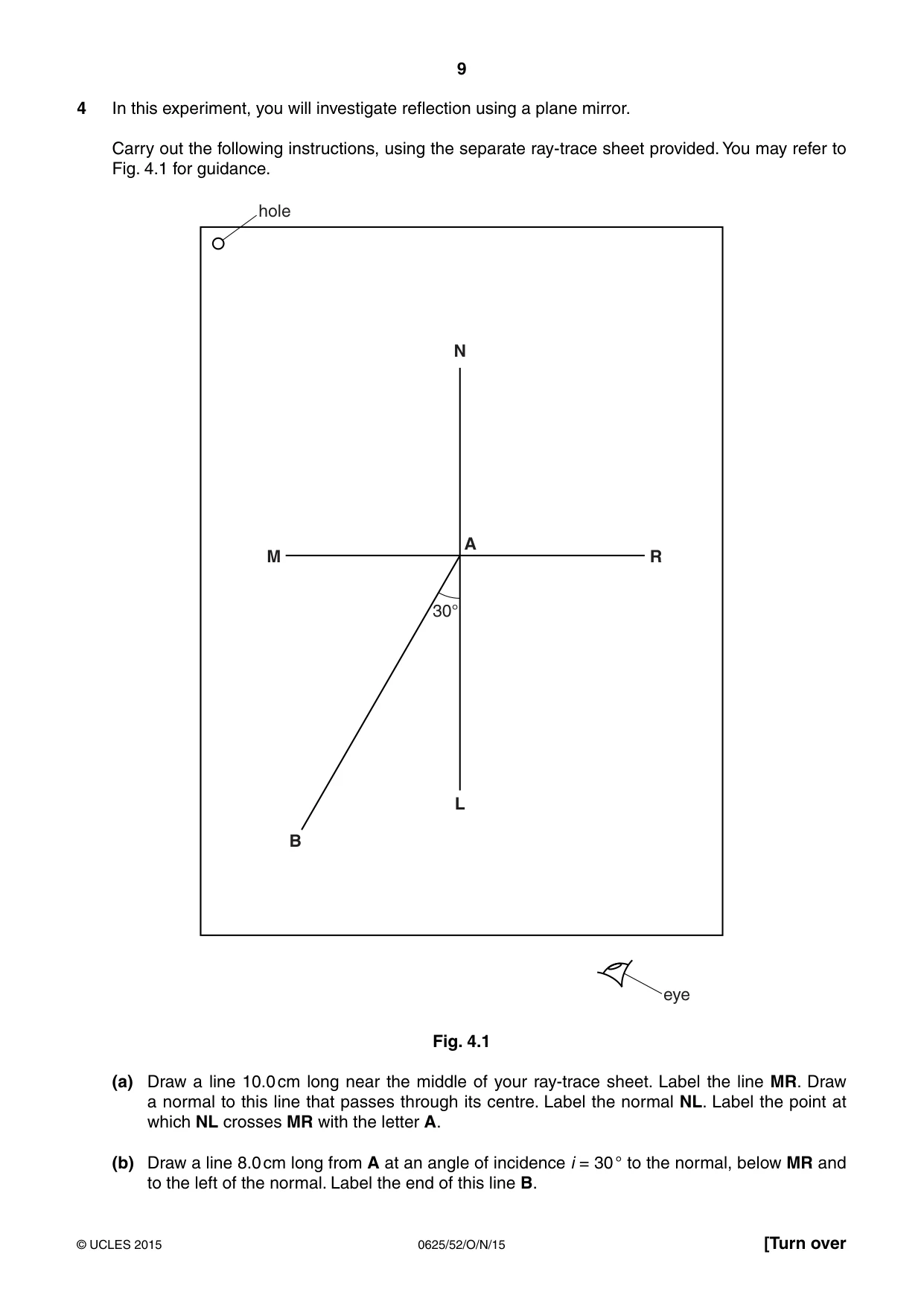
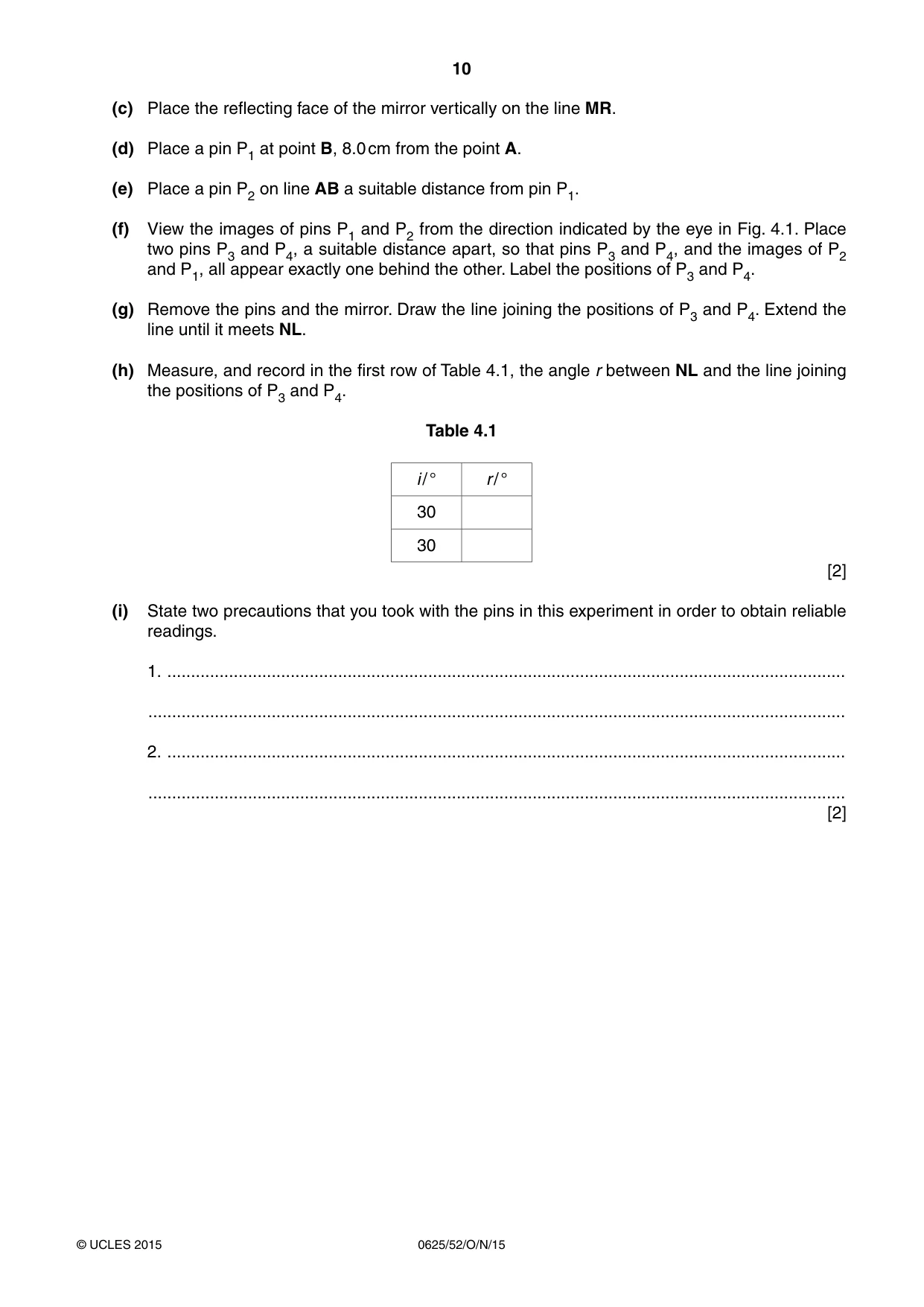
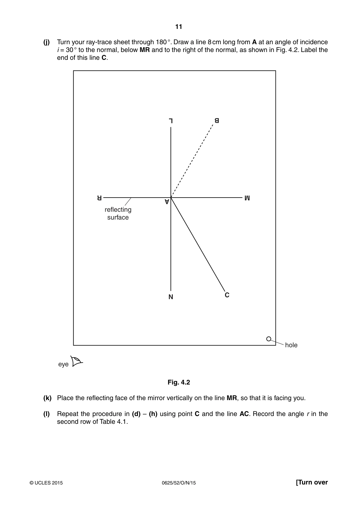
4 In this experiment, you will investigate reflection using a plane mirror. Carry out the following instructions, using the separate ray-trace sheet provided. You may refer to Fig. 4.1 for guidance. hole N A M R 30° L B eye Fig. 4.1 (a) Draw a line 10.0 cm long near the middle of your ray-trace sheet. Label the line MR. Draw a normal to this line that passes through its centre. Label the normal NL. Label the point at which NL crosses MR with the letter A. (b) Draw a line 8.0 cm long from A at an angle of incidence i = 30 ° to the normal, below MR and to the left of the normal. Label the end of this line B. (c) Place the reflecting face of the mirror vertically on the line MR. (d) Place a pin P1 at point B, 8.0 cm from the point A. (e) Place a pin P2 on line AB a suitable distance from pin P1. (f) View the images of pins P1 and P2 from the direction indicated by the eye in Fig. 4.1. Place two pins P3 and P4, a suitable distance apart, so that pins P3 and P4, and the images of P2 and P1, all appear exactly one behind the other. Label the positions of P3 and P4. (g) Remove the pins and the mirror. Draw the line joining the positions of P3 and P4. Extend the line until it meets NL. (h) Measure, and record in the first row of Table 4.1, the angle r between NL and the line joining the positions of P3 and P4. Table 4.1 i / ° r / ° 30 30 [2] (i) State two precautions that you took with the pins in this experiment in order to obtain reliable readings. 1. ............................................................................................................................................... ................................................................................................................................................... 2. ............................................................................................................................................... ................................................................................................................................................... [2] (j) Turn your ray-trace sheet through 180 °. Draw a line 8 cm long from A at an angle of incidence i = 30 ° to the normal, below MR and to the right of the normal, as shown in Fig. 4.2. Label the end of this line C. L B R M A reflecting surface N C hole eye Fig. 4.2 (k) Place the reflecting face of the mirror vertically on the line MR, so that it is facing you. (l) Repeat the procedure in (d) – (h) using point C and the line AC. Record the angle r in the second row of Table 4.1.
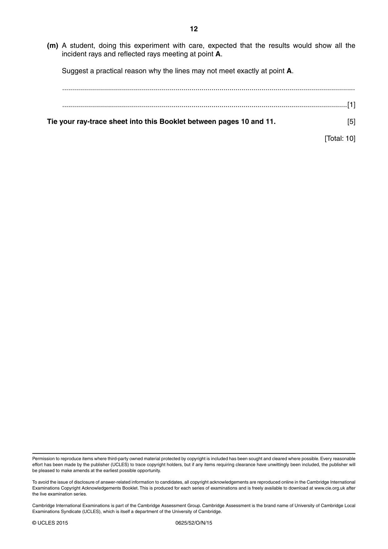
Mark scheme: 4(a)–(g) ray-trace: • normal drawn at centre of MR [1] • first incident ray at 30° (±1°) [1] • first P1P2 distance at least 5 cm apart [1] • both reflected rays in correct positions [1] • all lines correctly drawn and all lines single, thin, continuous lines [1] (h)(l) table: • r values correct to 1° (from trace) [1] • r values = 28–32 [1] (i) any two from: • ensure pins are vertical / align pins by viewing bases of pins • pins as far apart as possible (> 5 cm) • thin lines / sharp pencil / thin pins [2] (m) any one from: • thickness of mirror / mirror glass silvered at back surface • thickness of pins • difficulty in exactly lining up pins and their images [1] [Total: 10]
What was in this paper
The subtopics covered by these 4 questions, and how many questions each got. Open one in a new tab to see every Cambridge question on it.
What you needed in this session
Cambridge’s own grade thresholds for 2015 Oct/Nov, Paper 5 · Variant 2. A higher threshold means an easier paper — the bar moves with how the cohort did.