Cambridge IGCSE Physics 0625 — 2002 Oct/Nov Paper 3 · Variant 1
0625/31/O/N/02
The question paper and its mark scheme, free to read here and free to download. This is Cambridge’s own paper, exactly as it was sat.
Question paper16 pages

Mark scheme4 pages
Answers below. Sit the paper first if you are practising.
Paper as text
Question paper, page 1
TIME 1 hour 15 minutes INSTRUCTIONS TO CANDIDATES Write your name, Centre number and candidate number in the spaces at the top of this page. Answer all questions. Write your answers in the spaces provided on the question paper. INFORMATION FOR CANDIDATES The number of marks is given in brackets [ ] at the end of each question or part question. International General Certificate of Secondary Education CAMBRIDGE INTERNATIONAL EXAMINATIONS PHYSICS 0625/3 PAPER 3 OCTOBER/NOVEMBER SESSION 2002 1 hour 15 minutes Candidates answer on the question paper. No additional materials are required. This question paper consists of 14 printed pages and 2 blank pages. SP (NF/KS) S23400/3 © CIE 2002 [Turn over Candidate Centre Number Number Candidate Name FOR EXAMINER’S USE 1 2 3 4 5 10 7 6 9 8 TOTAL www.XtremePapers.com
Question paper, page 2
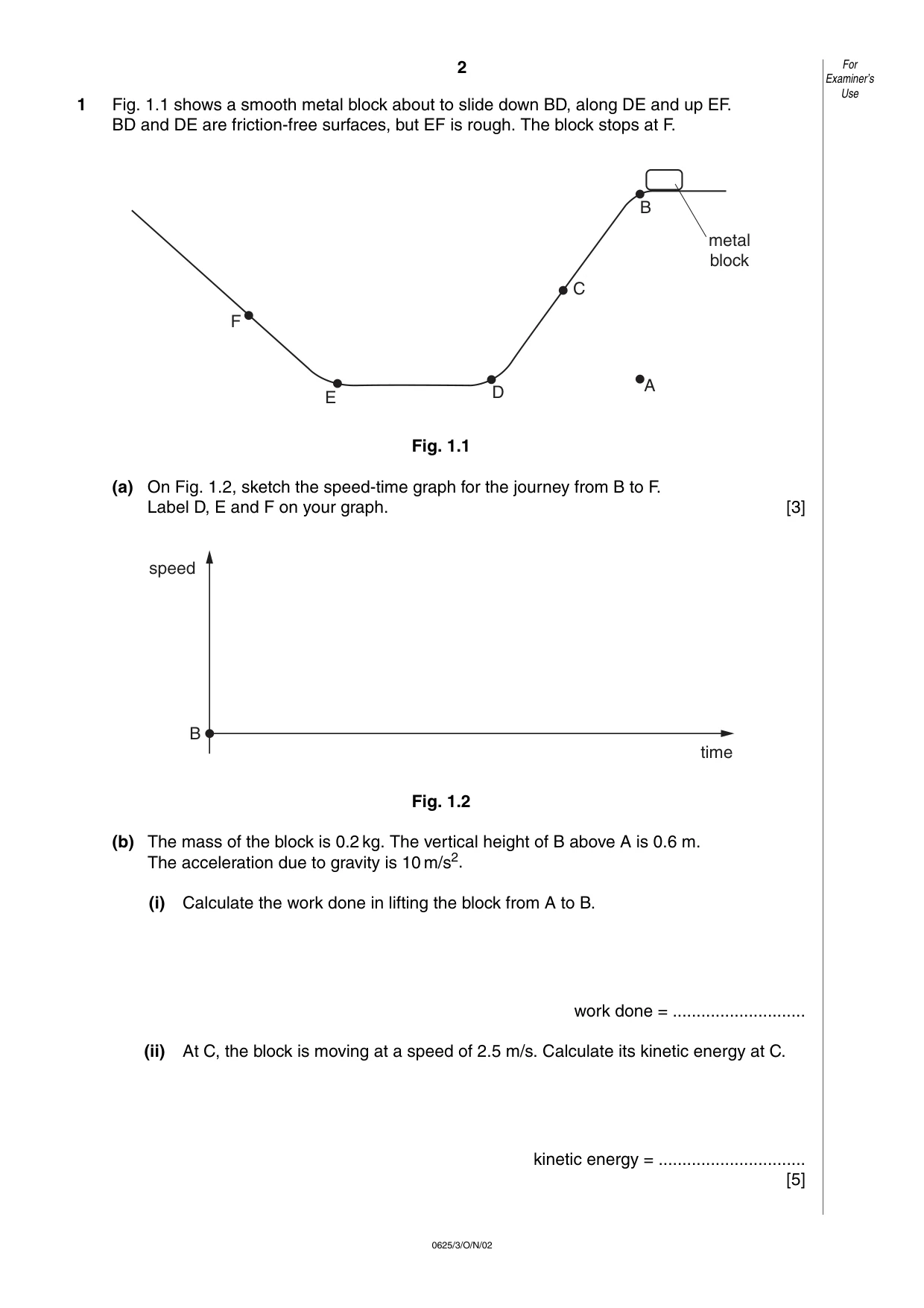
2 0625/3/O/N/02 1 Fig. 1.1 shows a smooth metal block about to slide down BD, along DE and up EF. BD and DE are friction-free surfaces, but EF is rough. The block stops at F. Fig. 1.1 (a) On Fig. 1.2, sketch the speed-time graph for the journey from B to F. Label D, E and F on your graph. [3] Fig. 1.2 (b) The mass of the block is 0.2 kg. The vertical height of B above A is 0.6 m. The acceleration due to gravity is 10 m/s2. (i) Calculate the work done in lifting the block from A to B. work done = … (ii) At C, the block is moving at a speed of 2.5 m/s. Calculate its kinetic energy at C. kinetic energy = … [5] time speed B A B C D E F metal block For Examiner’s Use
Question paper, page 3
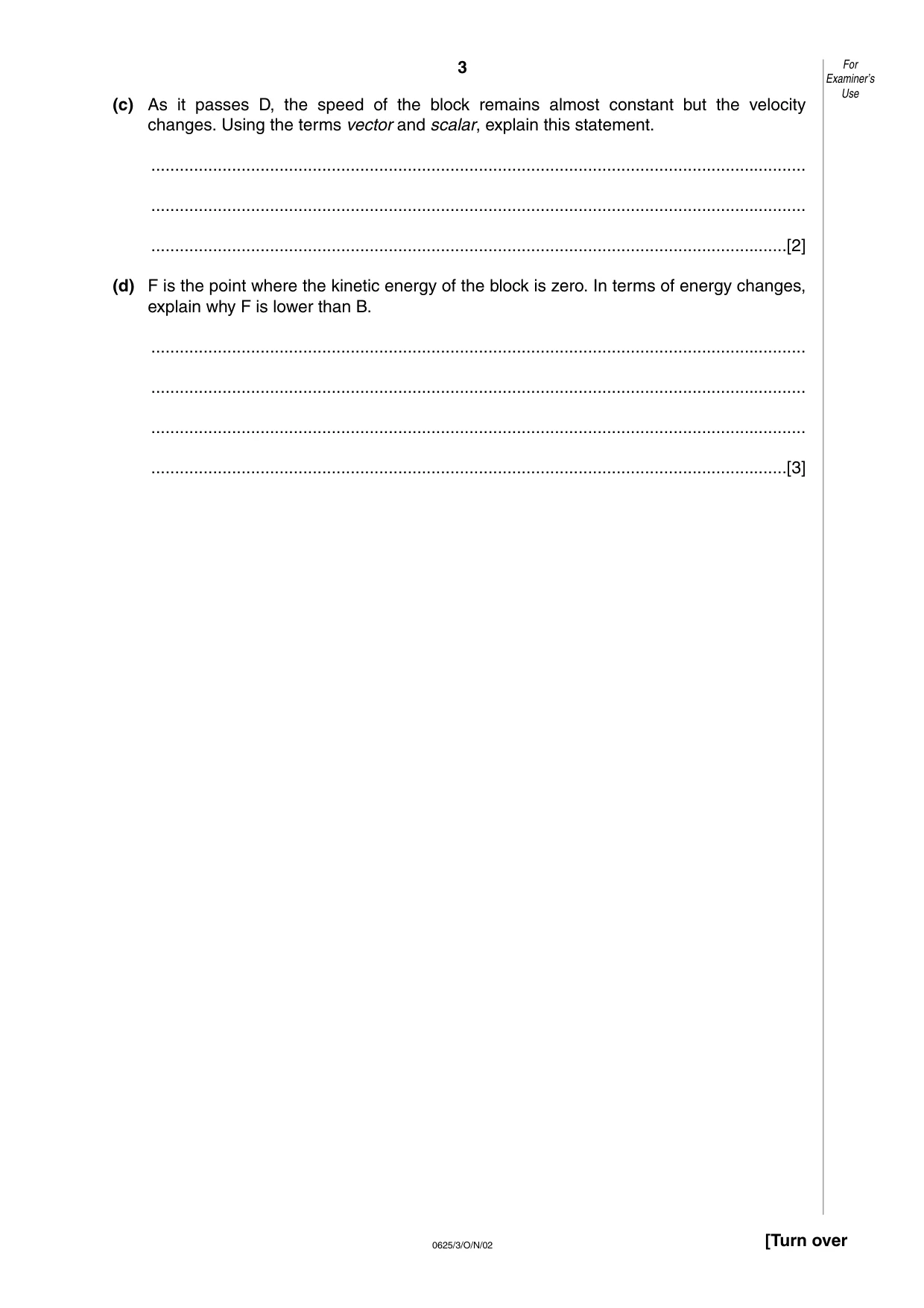
3 0625/3/O/N/02 [Turn over (c) As it passes D, the speed of the block remains almost constant but the velocity changes. Using the terms vector and scalar, explain this statement. … … …[2] (d) F is the point where the kinetic energy of the block is zero. In terms of energy changes, explain why F is lower than B. … … … …[3] For Examiner’s Use
Question paper, page 4
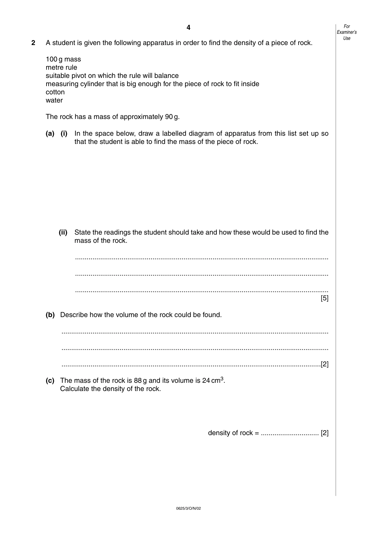
4 0625/3/O/N/02 2 A student is given the following apparatus in order to find the density of a piece of rock. 100 g mass metre rule suitable pivot on which the rule will balance measuring cylinder that is big enough for the piece of rock to fit inside cotton water The rock has a mass of approximately 90 g. (a) (i) In the space below, draw a labelled diagram of apparatus from this list set up so that the student is able to find the mass of the piece of rock. (ii) State the readings the student should take and how these would be used to find the mass of the rock. … … … [5] (b) Describe how the volume of the rock could be found. … … …[2] (c) The mass of the rock is 88 g and its volume is 24 cm3. Calculate the density of the rock. density of rock = … [2] For Examiner’s Use
Question paper, page 5
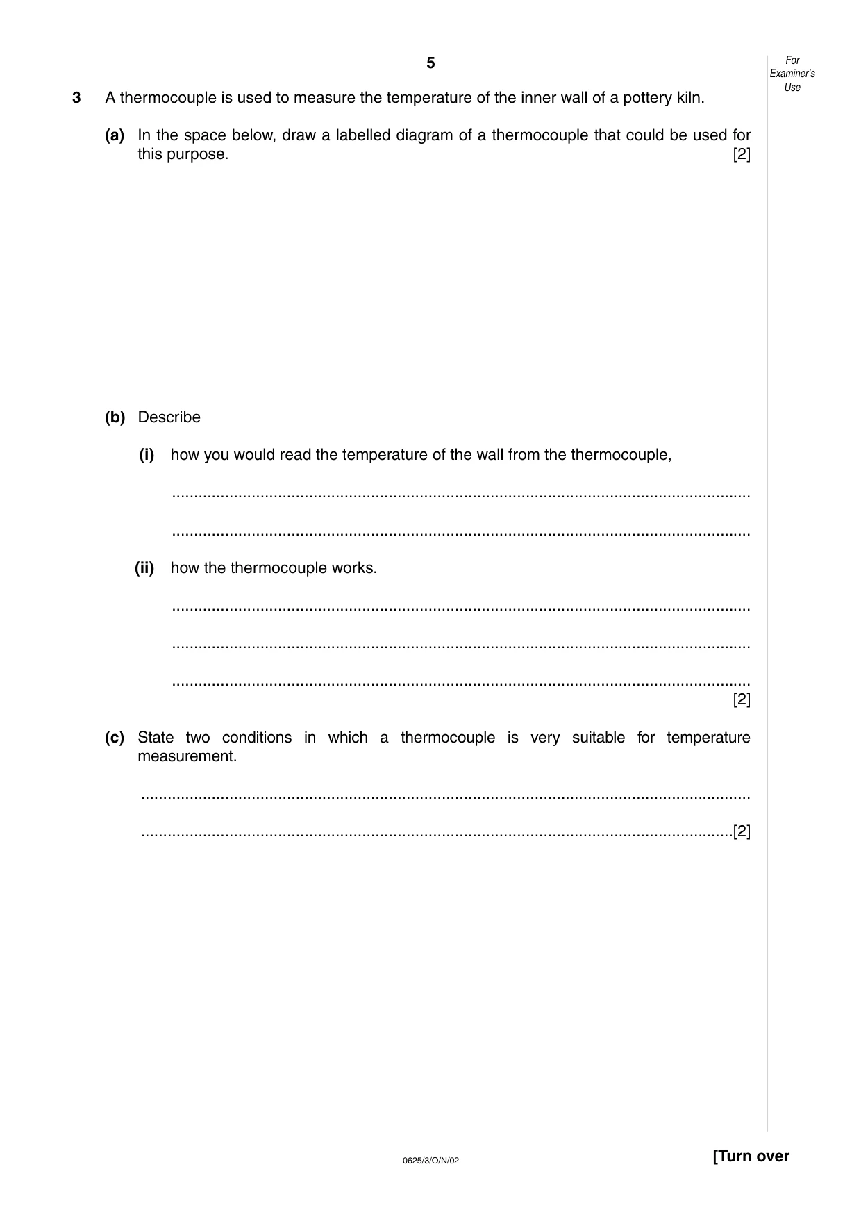
5 0625/3/O/N/02 [Turn over 3 A thermocouple is used to measure the temperature of the inner wall of a pottery kiln. (a) In the space below, draw a labelled diagram of a thermocouple that could be used for this purpose. [2] (b) Describe (i) how you would read the temperature of the wall from the thermocouple, … … (ii) how the thermocouple works. … … … [2] (c) State two conditions in which a thermocouple is very suitable for temperature measurement. … …[2] For Examiner’s Use
Question paper, page 6
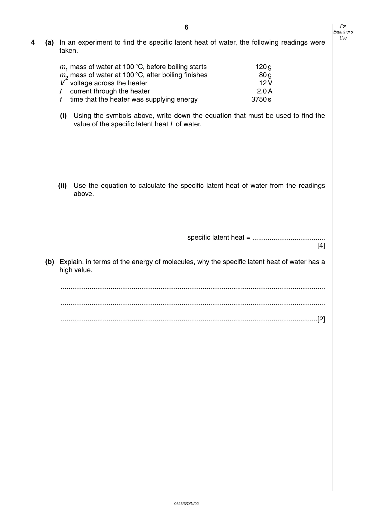
6 0625/3/O/N/02 4 (a) In an experiment to find the specific latent heat of water, the following readings were taken. m1 mass of water at 100 °C, before boiling starts 120 g m2 mass of water at 100 °C, after boiling finishes 80 g V voltage across the heater 12 V I current through the heater 2.0 A t time that the heater was supplying energy 3750 s (i) Using the symbols above, write down the equation that must be used to find the value of the specific latent heat L of water. (ii) Use the equation to calculate the specific latent heat of water from the readings above. specific latent heat = … [4] (b) Explain, in terms of the energy of molecules, why the specific latent heat of water has a high value. … … …[2] For Examiner’s Use
Question paper, page 7
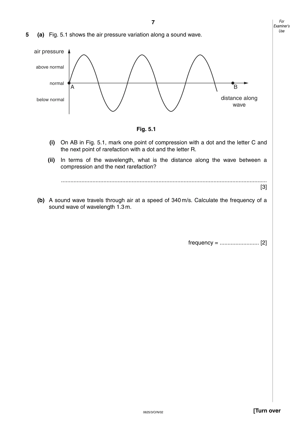
7 0625/3/O/N/02 [Turn over 5 (a) Fig. 5.1 shows the air pressure variation along a sound wave. Fig. 5.1 (i) On AB in Fig. 5.1, mark one point of compression with a dot and the letter C and the next point of rarefaction with a dot and the letter R. (ii) In terms of the wavelength, what is the distance along the wave between a compression and the next rarefaction? … [3] (b) A sound wave travels through air at a speed of 340 m/s. Calculate the frequency of a sound wave of wavelength 1.3 m. frequency = … [2] air pressure below normal normal distance along wave A B above normal For Examiner’s Use
Question paper, page 8
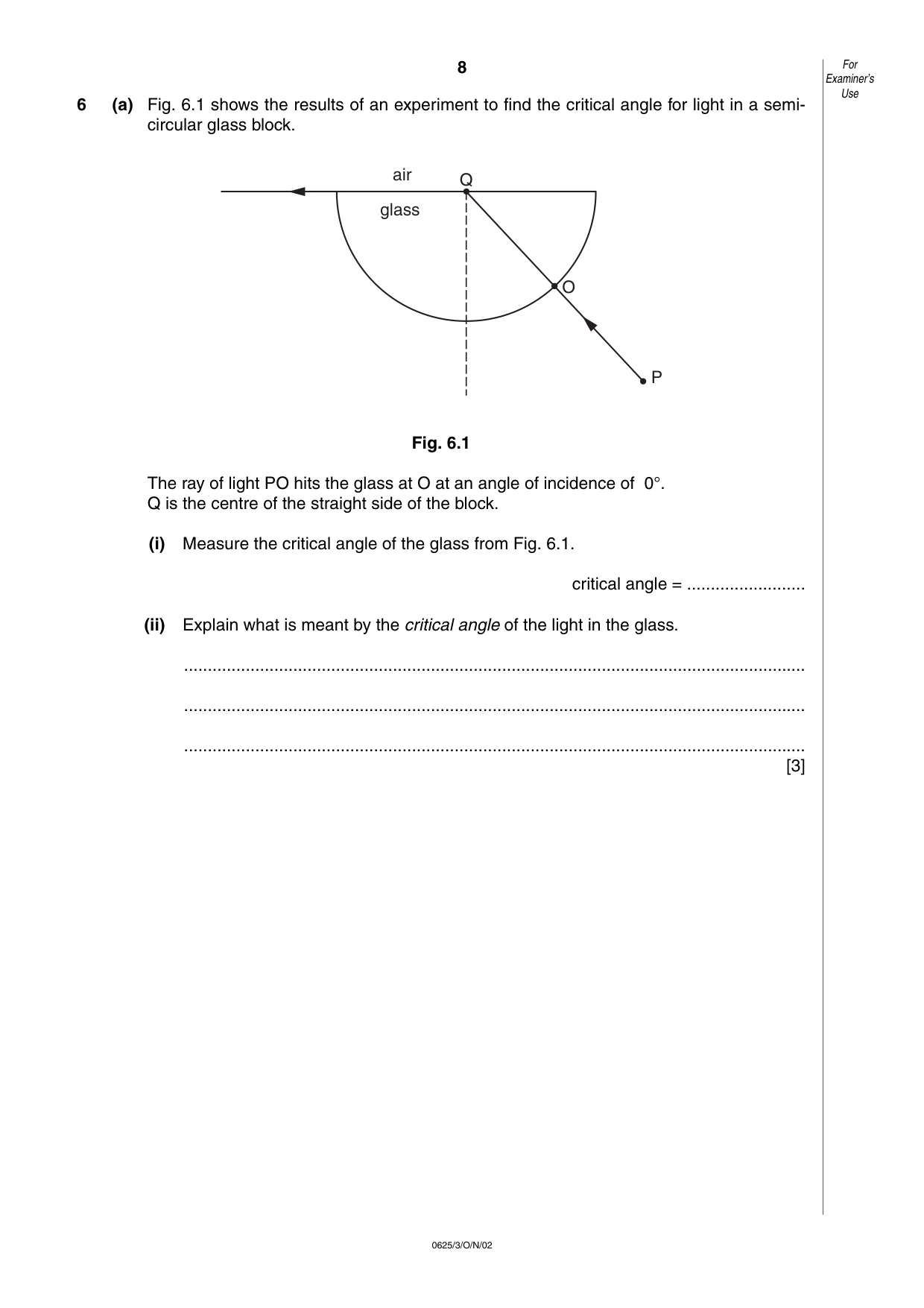
8 0625/3/O/N/02 6 (a) Fig. 6.1 shows the results of an experiment to find the critical angle for light in a semi- circular glass block. Fig. 6.1 The ray of light PO hits the glass at O at an angle of incidence of 0°. Q is the centre of the straight side of the block. (i) Measure the critical angle of the glass from Fig. 6.1. critical angle = … (ii) Explain what is meant by the critical angle of the light in the glass. … … … [3] air glass Q O P For Examiner’s Use
Question paper, page 9
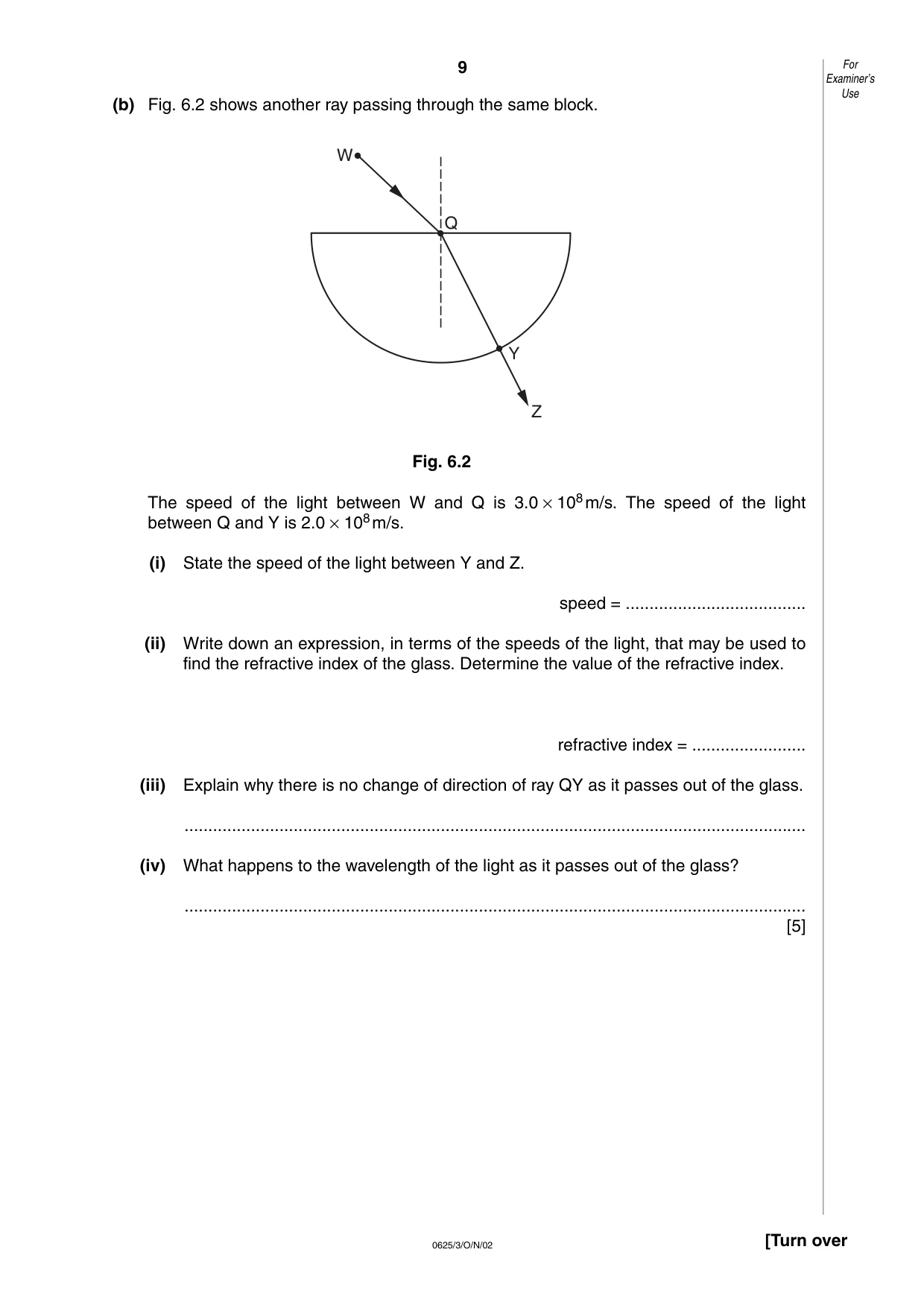
9 0625/3/O/N/02 [Turn over (b) Fig. 6.2 shows another ray passing through the same block. Fig. 6.2 The speed of the light between W and Q is 3.0 × 10⁸m/s. The speed of the light between Q and Y is 2.0 × 10⁸m/s. (i) State the speed of the light between Y and Z. speed = … (ii) Write down an expression, in terms of the speeds of the light, that may be used to find the refractive index of the glass. Determine the value of the refractive index. refractive index = … (iii) Explain why there is no change of direction of ray QY as it passes out of the glass. … (iv) What happens to the wavelength of the light as it passes out of the glass? … [5] Q W Y Z For Examiner’s Use
Question paper, page 10
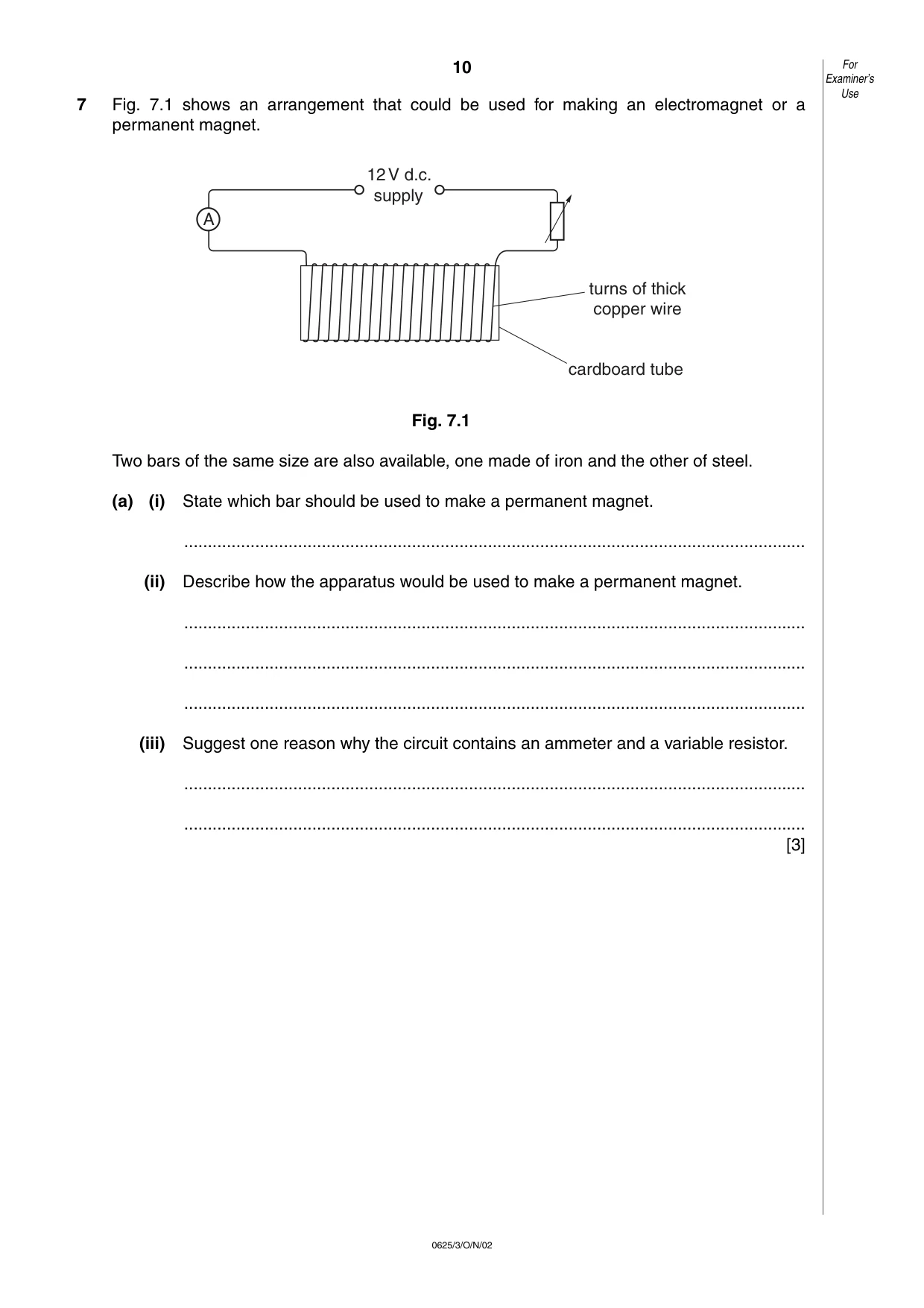
10 0625/3/O/N/02 7 Fig. 7.1 shows an arrangement that could be used for making an electromagnet or a permanent magnet. Fig. 7.1 Two bars of the same size are also available, one made of iron and the other of steel. (a) (i) State which bar should be used to make a permanent magnet. … (ii) Describe how the apparatus would be used to make a permanent magnet. … … … (iii) Suggest one reason why the circuit contains an ammeter and a variable resistor. … … [3] A 12V d.c. supply turns of thick copper wire cardboard tube For Examiner’s Use
Question paper, page 11
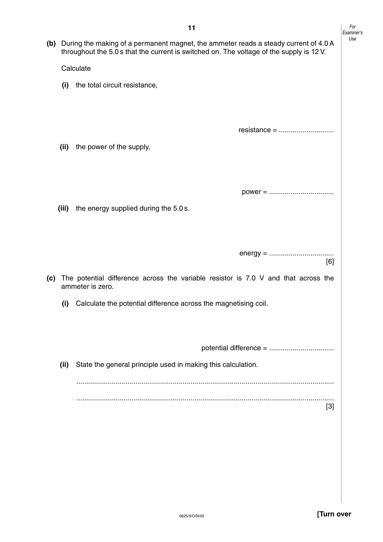
11 0625/3/O/N/02 [Turn over (b) During the making of a permanent magnet, the ammeter reads a steady current of 4.0 A throughout the 5.0 s that the current is switched on. The voltage of the supply is 12 V. Calculate (i) the total circuit resistance, resistance = … (ii) the power of the supply, power = … (iii) the energy supplied during the 5.0 s. energy = … [6] (c) The potential difference across the variable resistor is 7.0 V and that across the ammeter is zero. (i) Calculate the potential difference across the magnetising coil. potential difference = … (ii) State the general principle used in making this calculation. … … [3] For Examiner’s Use
Question paper, page 12
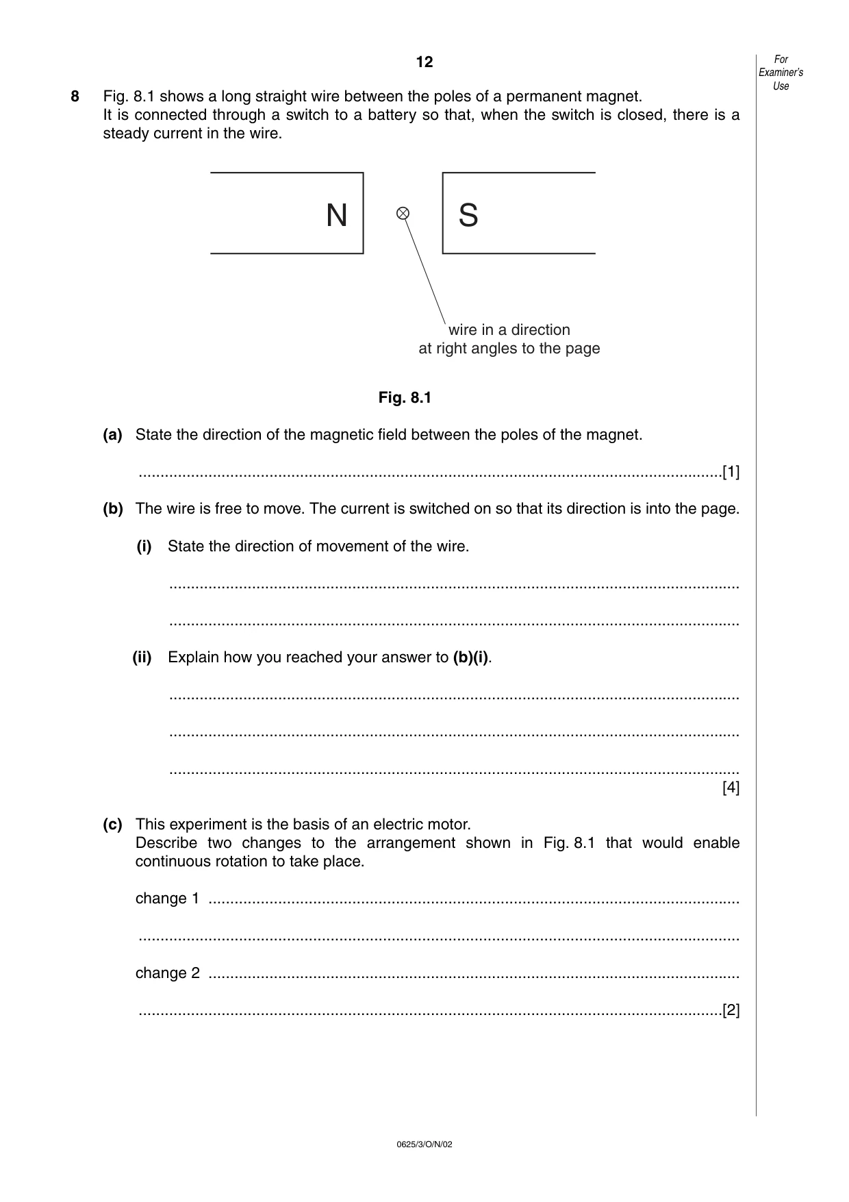
12 0625/3/O/N/02 8 Fig. 8.1 shows a long straight wire between the poles of a permanent magnet. It is connected through a switch to a battery so that, when the switch is closed, there is a steady current in the wire. Fig. 8.1 (a) State the direction of the magnetic field between the poles of the magnet. …[1] (b) The wire is free to move. The current is switched on so that its direction is into the page. (i) State the direction of movement of the wire. … … (ii) Explain how you reached your answer to (b)(i). … … … [4] (c) This experiment is the basis of an electric motor. Describe two changes to the arrangement shown in Fig. 8.1 that would enable continuous rotation to take place. change 1 … … change 2 … …[2] N S wire in a direction at right angles to the page For Examiner’s Use
Question paper, page 13
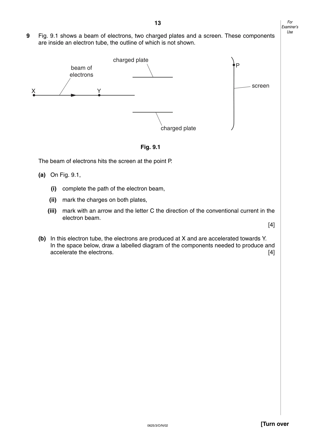
13 0625/3/O/N/02 [Turn over 9 Fig. 9.1 shows a beam of electrons, two charged plates and a screen. These components are inside an electron tube, the outline of which is not shown. Fig. 9.1 The beam of electrons hits the screen at the point P. (a) On Fig. 9.1, (i) complete the path of the electron beam, (ii) mark the charges on both plates, (iii) mark with an arrow and the letter C the direction of the conventional current in the electron beam. [4] (b) In this electron tube, the electrons are produced at X and are accelerated towards Y. In the space below, draw a labelled diagram of the components needed to produce and accelerate the electrons. [4] X Y P screen charged plate charged plate beam of electrons For Examiner’s Use
Question paper, page 14
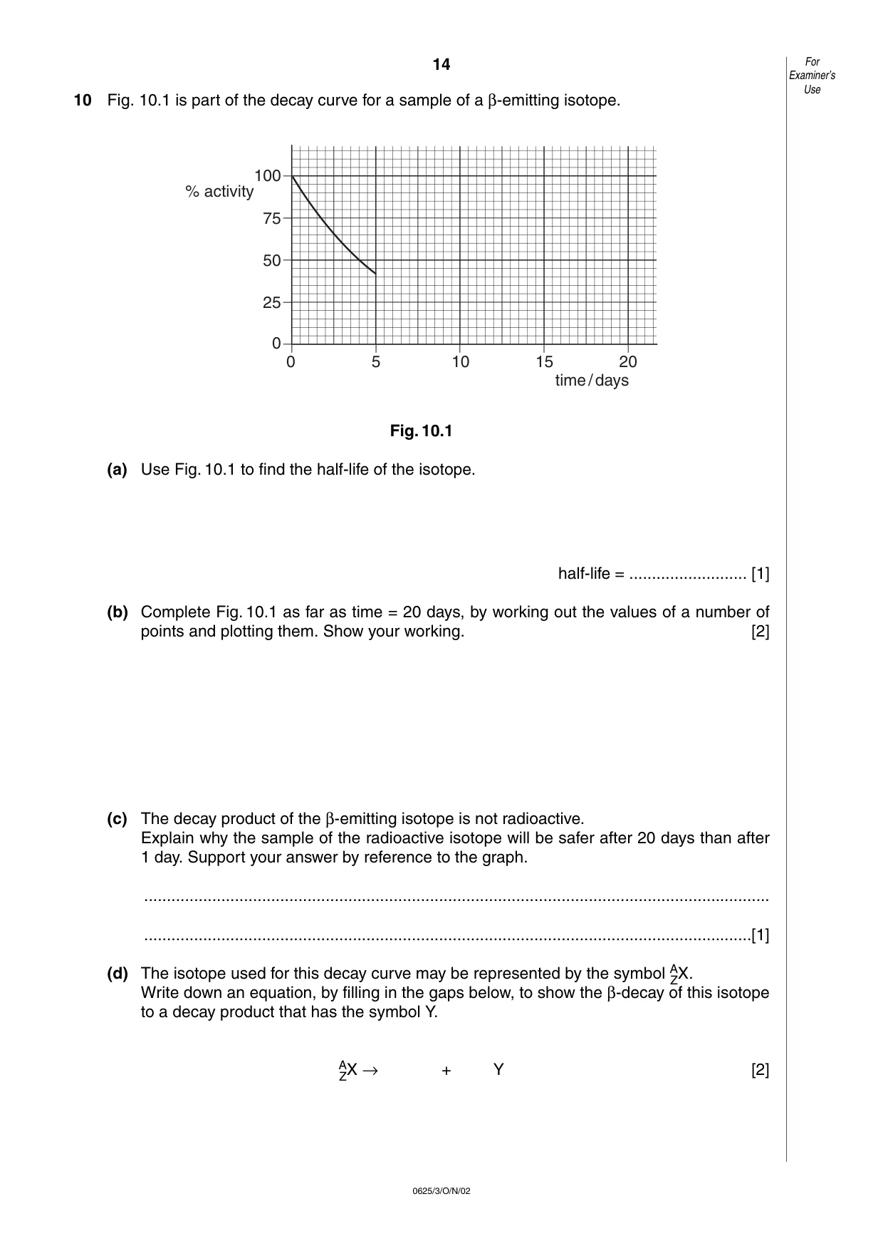
14 0625/3/O/N/02 10 Fig. 10.1 is part of the decay curve for a sample of a β-emitting isotope. Fig. 10.1 (a) Use Fig. 10.1 to find the half-life of the isotope. half-life = … [1] (b) Complete Fig. 10.1 as far as time = 20 days, by working out the values of a number of points and plotting them. Show your working. [2] (c) The decay product of the β-emitting isotope is not radioactive. Explain why the sample of the radioactive isotope will be safer after 20 days than after 1 day. Support your answer by reference to the graph. … …[1] (d) The isotope used for this decay curve may be represented by the symbol A ZX. Write down an equation, by filling in the gaps below, to show the β-decay of this isotope to a decay product that has the symbol Y. A ZX → + Y [2] 100 75 50 25 0 0 5 10 15 20 % activity time/days For Examiner’s Use
Mark scheme, page 1
CAMBRIDGE INTERNATIONAL EXAMINATIONS NOVEMBER 2002 INTERNATIONAL GCSE UNIVERSITY of CAMBRIDGE Local Examinations Syndicate
Mark scheme, page 2
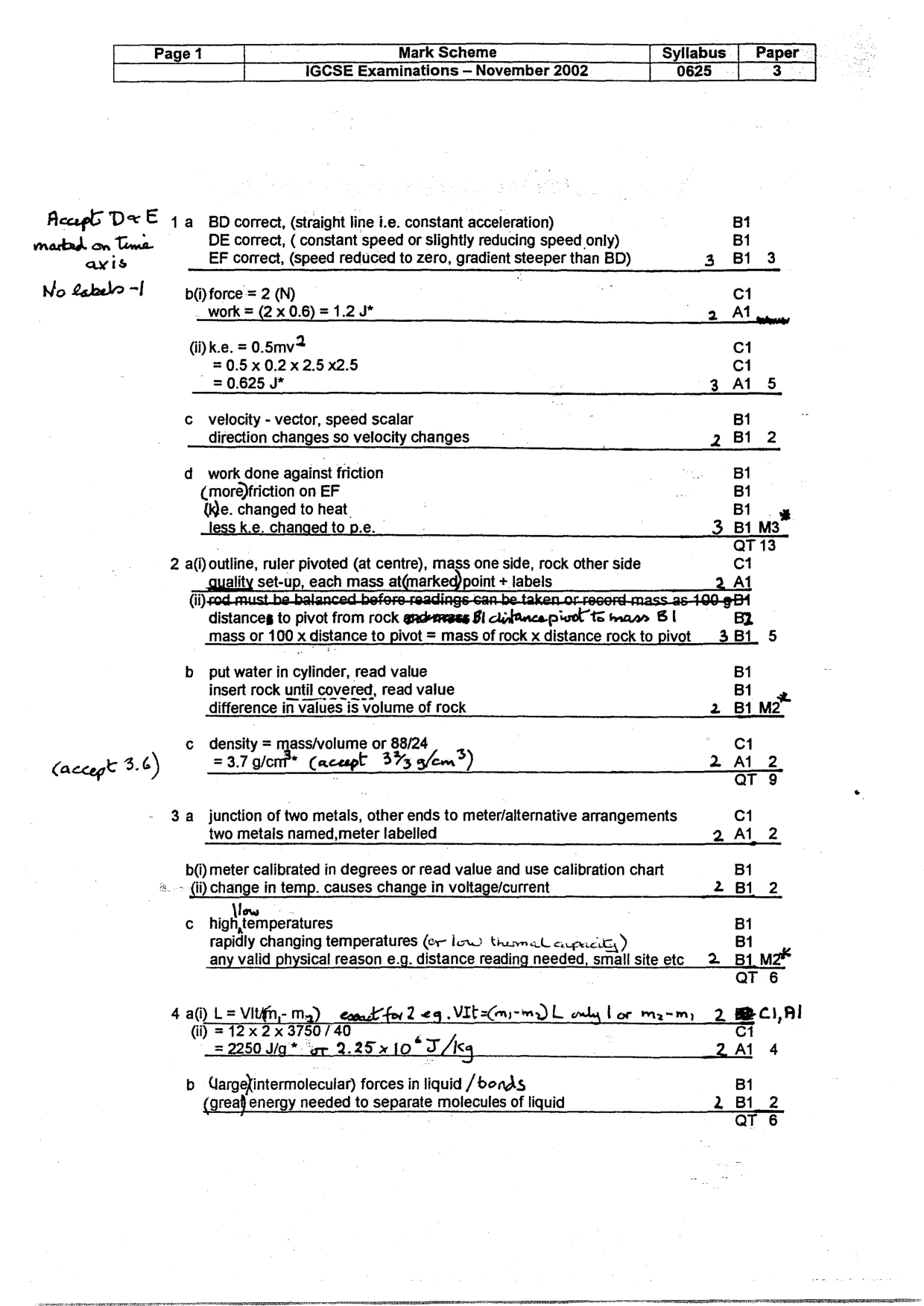
Page 1 Mark Scheme Syllabus Paper IGCSE Examinations — November 2002 0625 a Acap6 Dx E 4 BD correct, (straight line i.e. constant acceleration) Bt martad. on Toma DE correct, ( constant speed or slightly reducing speed only) Bi avis EF correct, (speed reduced to zero, gradient steeper than BD) 3 B13 No Sabelo-1 by force = 2 (N) : 1 work = (2 x 0.6) = 1.2 J* 2 Al (i)k.e. = 0.5mv C1 =0.5x0.2x2.5x2.5 C1 = 0.625 J* 3 Al 5 c velocity - vector, speed scalar B1 direction changes so velocity changes 2 B1 2 d_ work done against friction BI (more)friction on EF Bi We. changed to heat Bi oy Jess k.e. changed to p.e. 3_B1 M3 QT 13 2 a(i) outline, ruler pivoted (at centre), mass one side, rock other side ct aula set-u Up. each mass ganar + labels_ 2 Al mass or 100 x distance to pivot = mass of rock x distance. rock to pivot _ _3Bi 5 b put water in cylinder, read value Bi insert rock until covered, read value B1 difference in values is Volume of rock 2 Bi M2 c density = mass/volume on §8/24 3 C1 (accept 3.6) =3,7 g/ont* (acept 37% 3/em®) 2 AL 2 3a junction of two metals, other ends to meter/alternative arrangements C1 two metals named,meter labelled 2A1 2 b() meter calibrated in degrees or read value and use calibration chart BI «.~ (ii) change in temp. causes change in voltage/current 2 B12 | Mow c_ high,temperatures B1 rapidly changing temperatures (er Ino tiunnal expects) Bi any valid physical reason e.g. distance reading needed, small site etc 2 Bt mz QT 6 4a(i) L=Vitifn,- ma) ecoak for 2 ¢g VIt=Cri-ma L only Lor mam 2. BC, Al (i) = 12x 2x 3750740 = 2250 W/g* ‘er 2.25.10 *TAcq 2 Al 4 b UargeXintermolecular) forces in liquid /bonds Bi (gread energy needed to separate molecules of liquid 2 Bi 2 QT 6
Mark scheme, page 3
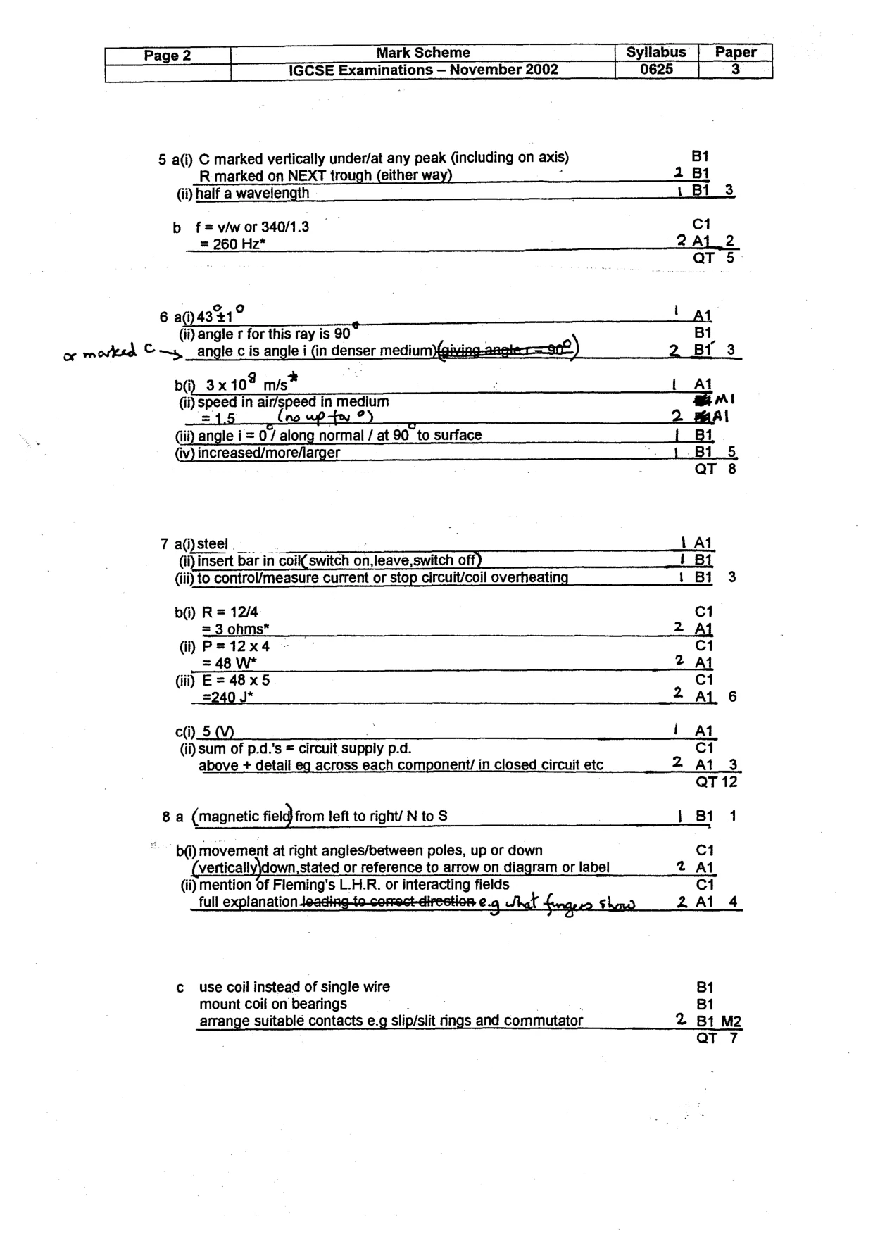
[ Page 2 Mark Scheme ‘Syllabus | Paper { IGCSE Examinations — November 2002 0625 | 3 5 a(i) C marked vertically under/at any peak (including on axis) Bi R marked on NEXT trough (either way) a Bi (i) half a wavelength 1 Bi 3 b f= vw or 340/1.3 C1 = 260 Hz* 2 AL 2 QT 5 6 (431? tat (ji) angle r for this ray is 30° B1 or movksd © ~s angle c is angle i (in denser medium)(gixing-angter=—e0 i ) 2 Br 3 b@_3x 10% mis* : Lat (ji) speed in air/speed in medium Mi =15 (ne up tu ?) >—<—$—<$< 2 marl (ii) angle i = 0 / along normal / at 90_to surface {| B1 (iv) increased/more/larger j_B1 5 QT 8 7 a()steel LA1 (ii)insert bar in coi switch on,leave,switch off) i Bt (ii) to control/measure current or stop circuit/coil overheating _ 1 Bi 3 b() R= 12/4 c1 =3 ohms* 2 AL (i) P=12x4 . C1 = 48 W* 2 AL di) E=48x5 ci =240 J* 2 AL 6 c()_5 (VY) i At (ii) sum of p.d.'s = circuit supply p.d. C1 above + detail eg across each component/ in closed circuit etc 2 At 3 QT 12 8 a (magnetic fielg from left to right/ N to S 1811 b(i) movement at right angles/between poles, up or down C1 ‘vertically\down, stated or reference to arrow on diagram or label 2 At (i) mention of Fleming's L.H.R. or interacting fields ci full explanation loading to. conset-direstion 2.9 Teak Lengeen sho ZA1L 4 c_ use Coil instead of single wire B1 mount coil on bearings B1 arrange suitable contacts e.g slip/slit rings and commutator 2 Bt M2 Qt 7
Mark scheme, page 4
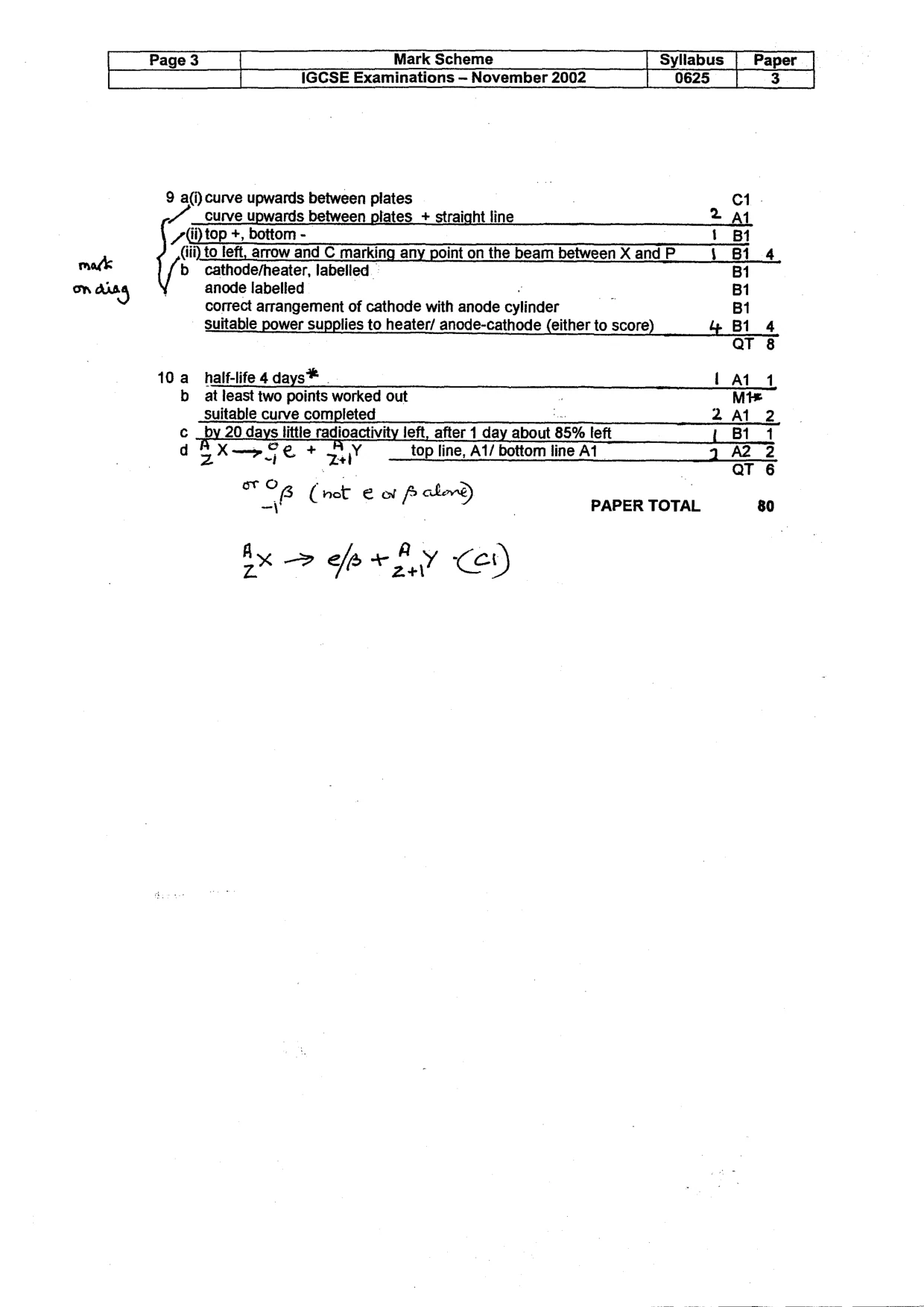
Page 3 Mark Scheme Syllabus | Paper IGCSE Examinations — November 2002 0625 3 9 a(i) curve upwards between plates C1 Curve upwards between plates + straight line _2aAtL 7(ijtop +, bottom - 1 Bi (iii) to left, arrow and C marking any point on the beam between X and P \_ Bi 4 matk b cathode/heater, labelled BI on re) anode labelled Bi correct arrangement of cathode with anode cylinder B1 Suitable power supplies to heater/ anode-cathode (either to score) 4 Bi 4 QT 8 10a half-life 4 days®* Lat b at least two points worked out Mt suitable curve completed 2A1 2 c by 20 days. little radioactivity left, after 1 day about 85% left {B11 d X—>2 1& + Y top line, A1/ bottom line A1 2 A2 2 zZ Zl aT 6 oro ; a fp hove Uh (ret eof ) PAPER TOTAL 80 Ax > eax fy cet)