Cambridge IGCSE Design and Technology 0445 — 2009 Oct/Nov Paper 3 · Variant 1
0445/31/O/N/09 · 50 marks · ≈56 min
The question paper and its mark scheme, free to read here and free to download. This is Cambridge’s own paper, exactly as it was sat.
Question paper20 pages


Mark scheme6 pages
Answers below. Sit the paper first if you are practising.
Paper as text
Question paper, page 1
READ THESE INSTRUCTIONS FIRST Write your Centre number, candidate number and name on all the work you hand in. Write in blue or black pen. You may use a soft pencil for any diagrams, graphs or rough working. Do not use staples, paper clips, highlighters, glue or correction fl uid. DO NOT WRITE IN ANY BARCODES. Section A Answer all questions in this section. Section B Answer one question in this section. You may use a calculator. The total of the marks for this paper is 50. The number of marks is given in brackets [ ] at the end of each question or part question. DESIGN AND TECHNOLOGY 0445/03 Paper 3 Resistant Materials October/November 2009 1 hour Candidates answer on the Question Paper. No Additional Materials are required. To be taken together with Paper 1 in one session of 2 hours 15 minutes. UNIVERSITY OF CAMBRIDGE INTERNATIONAL EXAMINATIONS International General Certifi cate of Secondary Education This document consists of 17 printed pages and 3 blank pages. [Turn over IB09 11_0445_03/3RP © UCLES 2009 *9570240298* For Examiner’s Use Total Section A Section B www.XtremePapers.com
Question paper, page 2
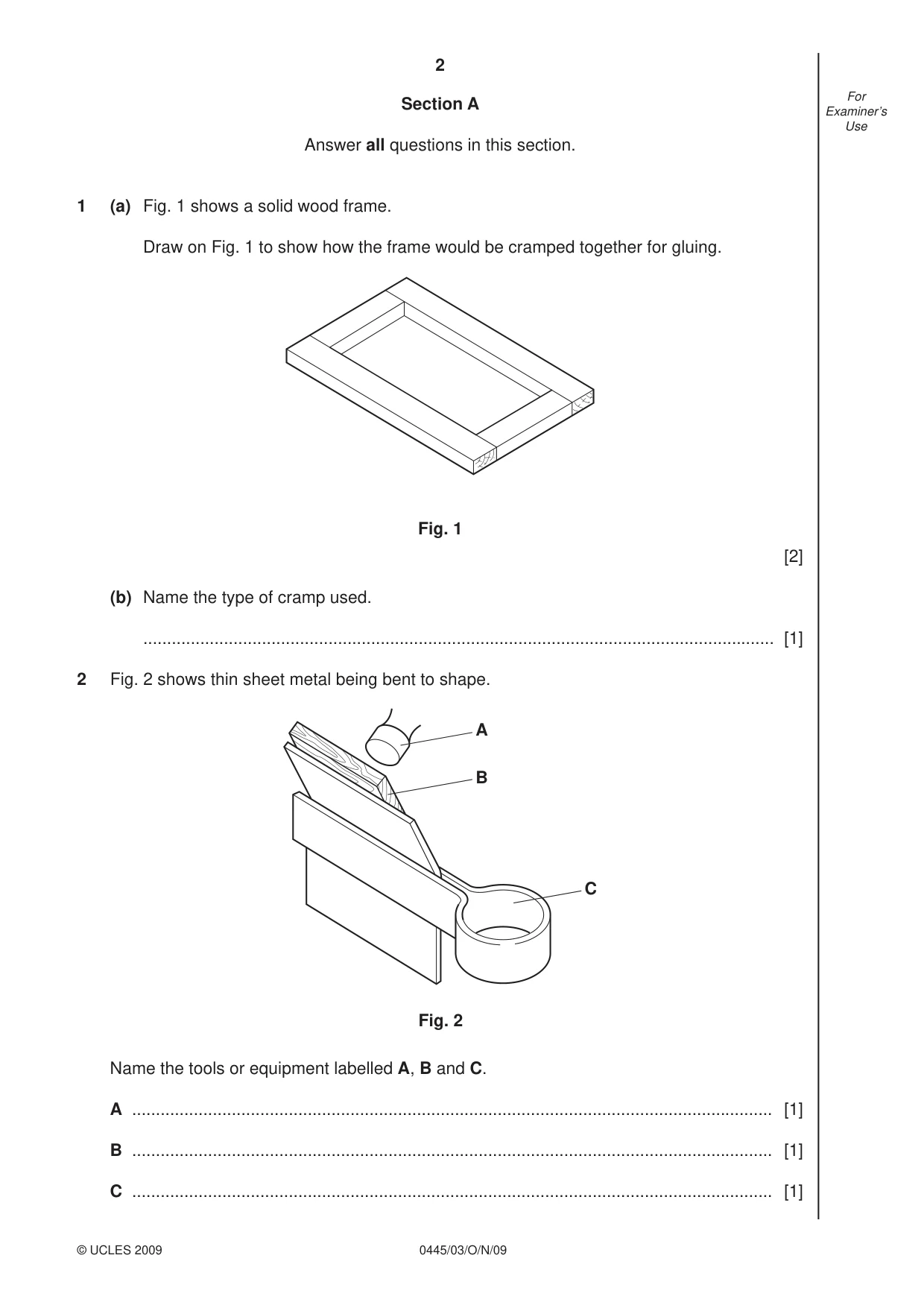
2 0445/03/O/N/09 © UCLES 2009 For Examiner’s Use Section A Answer all questions in this section. 1 (a) Fig. 1 shows a solid wood frame. Draw on Fig. 1 to show how the frame would be cramped together for gluing. Fig. 1 [2] (b) Name the type of cramp used. … [1] 2 Fig. 2 shows thin sheet metal being bent to shape. A B C Fig. 2 Name the tools or equipment labelled A, B and C. A … [1] B … [1] C … [1]
Question paper, page 3
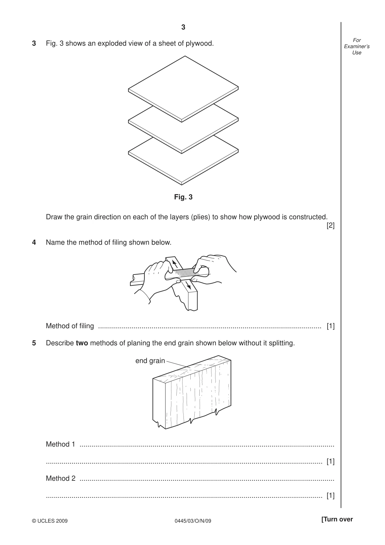
3 0445/03/O/N/09 © UCLES 2009 [Turn over For Examiner’s Use 3 Fig. 3 shows an exploded view of a sheet of plywood. Fig. 3 Draw the grain direction on each of the layers (plies) to show how plywood is constructed. [2] 4 Name the method of fi ling shown below. Method of fi ling … [1] 5 Describe two methods of planing the end grain shown below without it splitting. end grain Method 1 … … [1] Method 2 … … [1]
Question paper, page 4
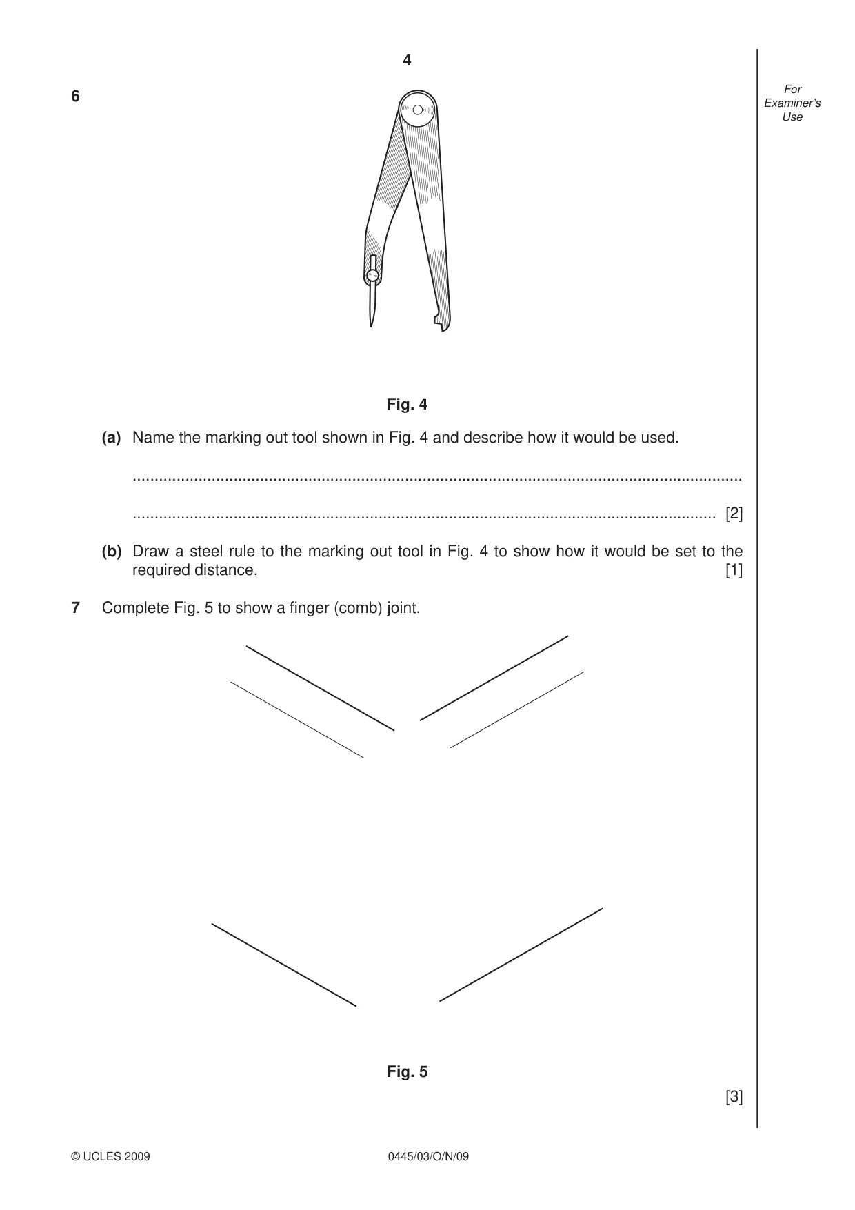
4 0445/03/O/N/09 © UCLES 2009 For Examiner’s Use 6 (a) Name the marking out tool shown in Fig. 4 and describe how it would be used. … … [2] (b) Draw a steel rule to the marking out tool in Fig. 4 to show how it would be set to the required distance. [1] 7 Complete Fig. 5 to show a fi nger (comb) joint. Fig. 5 [3] Fig. 4
Question paper, page 5
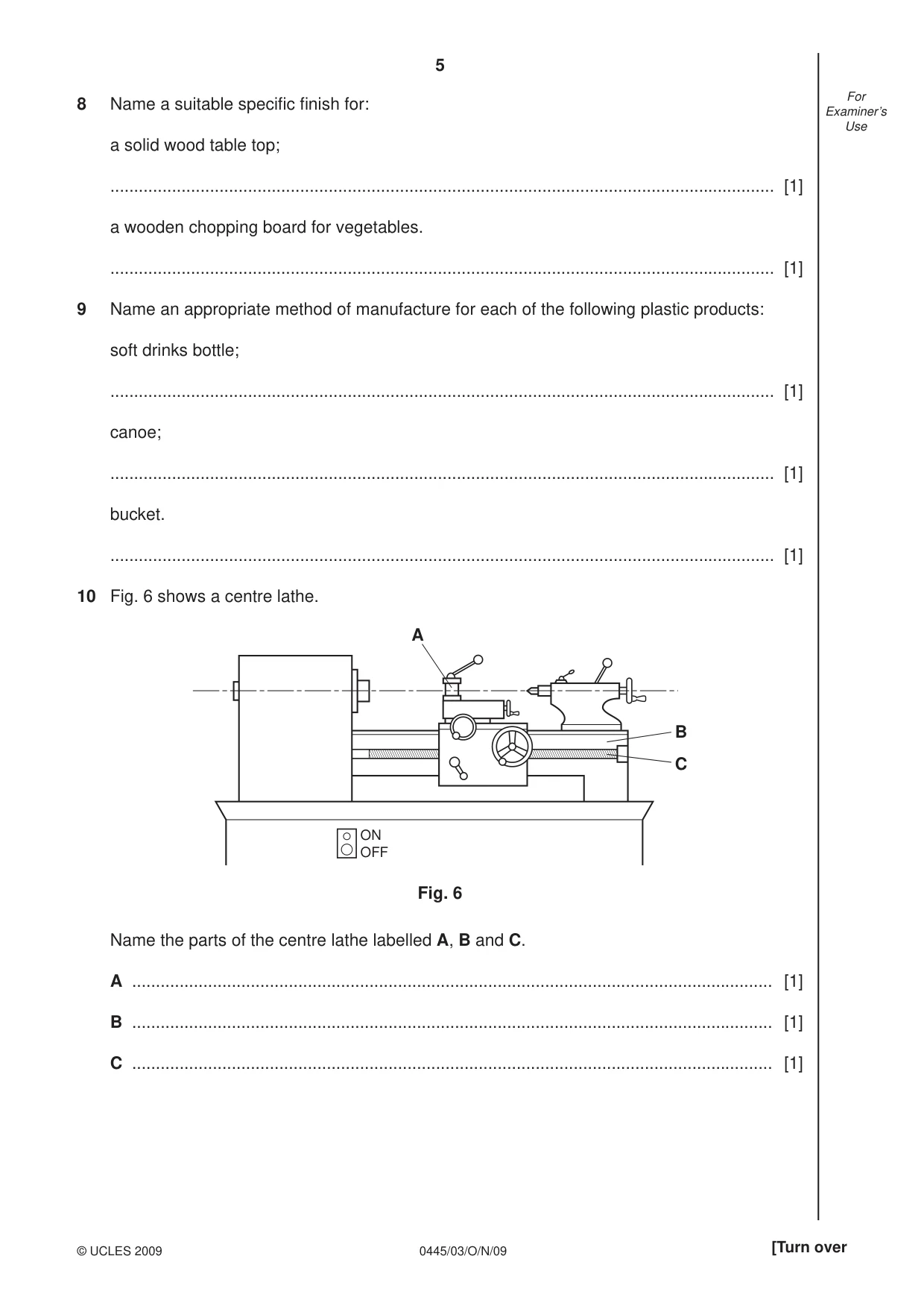
5 0445/03/O/N/09 © UCLES 2009 [Turn over For Examiner’s Use 8 Name a suitable specifi c fi nish for: a solid wood table top; … [1] a wooden chopping board for vegetables. … [1] 9 Name an appropriate method of manufacture for each of the following plastic products: soft drinks bottle; … [1] canoe; … [1] bucket. … [1] 10 Fig. 6 shows a centre lathe. ON OFF A B C Fig. 6 Name the parts of the centre lathe labelled A, B and C. A … [1] B … [1] C … [1]
Question paper, page 6
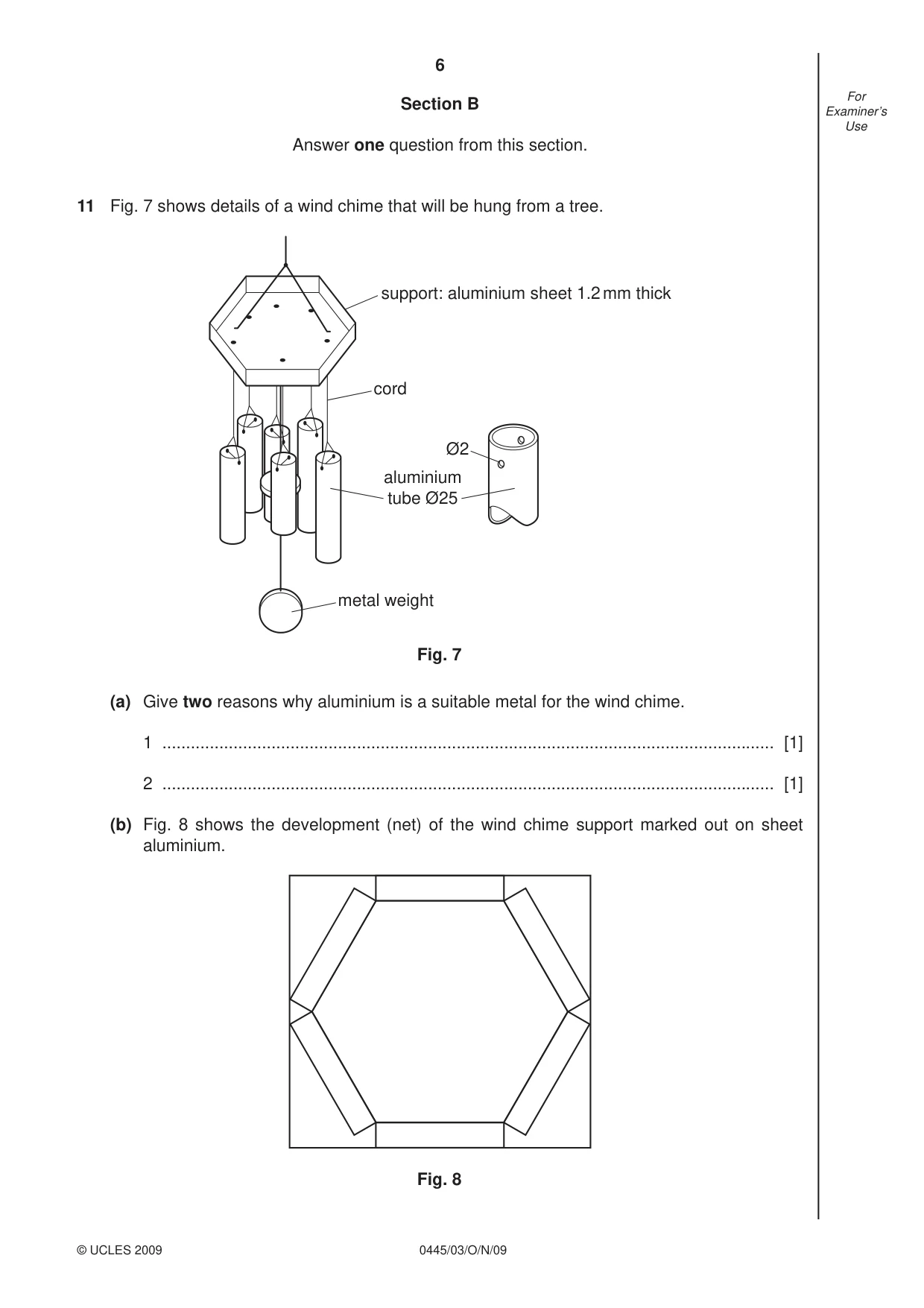
6 0445/03/O/N/09 © UCLES 2009 For Examiner’s Use Section B Answer one question from this section. 11 Fig. 7 shows details of a wind chime that will be hung from a tree. support: aluminium sheet 1.2 mm thick cord metal weight aluminium tube Ø25 Ø2 Fig. 7 (a) Give two reasons why aluminium is a suitable metal for the wind chime. 1 … [1] 2 … [1] (b) Fig. 8 shows the development (net) of the wind chime support marked out on sheet aluminium. Fig. 8
Question paper, page 7
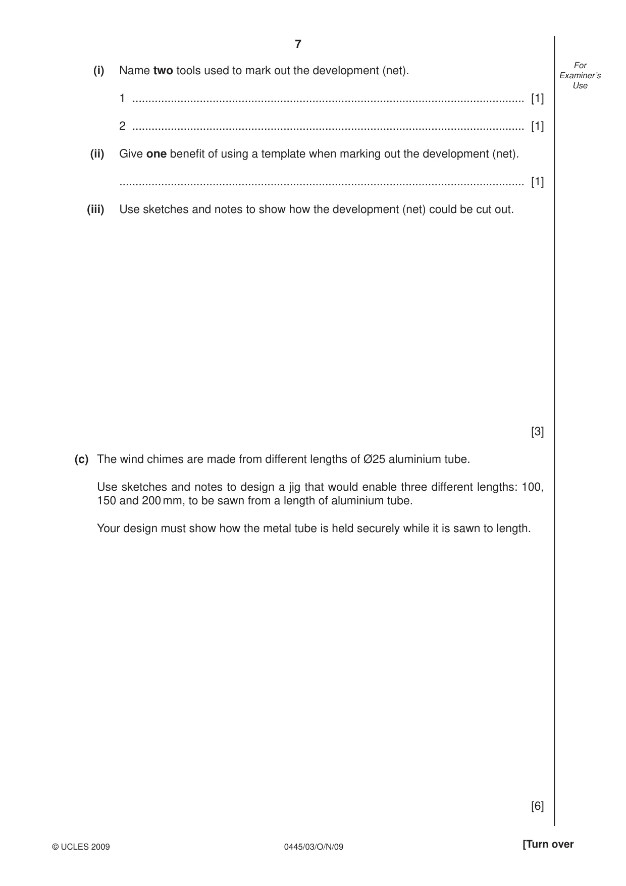
7 0445/03/O/N/09 © UCLES 2009 [Turn over For Examiner’s Use (i) Name two tools used to mark out the development (net). 1 … [1] 2 … [1] (ii) Give one benefi t of using a template when marking out the development (net). … [1] (iii) Use sketches and notes to show how the development (net) could be cut out. [3] (c) The wind chimes are made from different lengths of Ø25 aluminium tube. Use sketches and notes to design a jig that would enable three different lengths: 100, 150 and 200 mm, to be sawn from a length of aluminium tube. Your design must show how the metal tube is held securely while it is sawn to length. [6]
Question paper, page 8
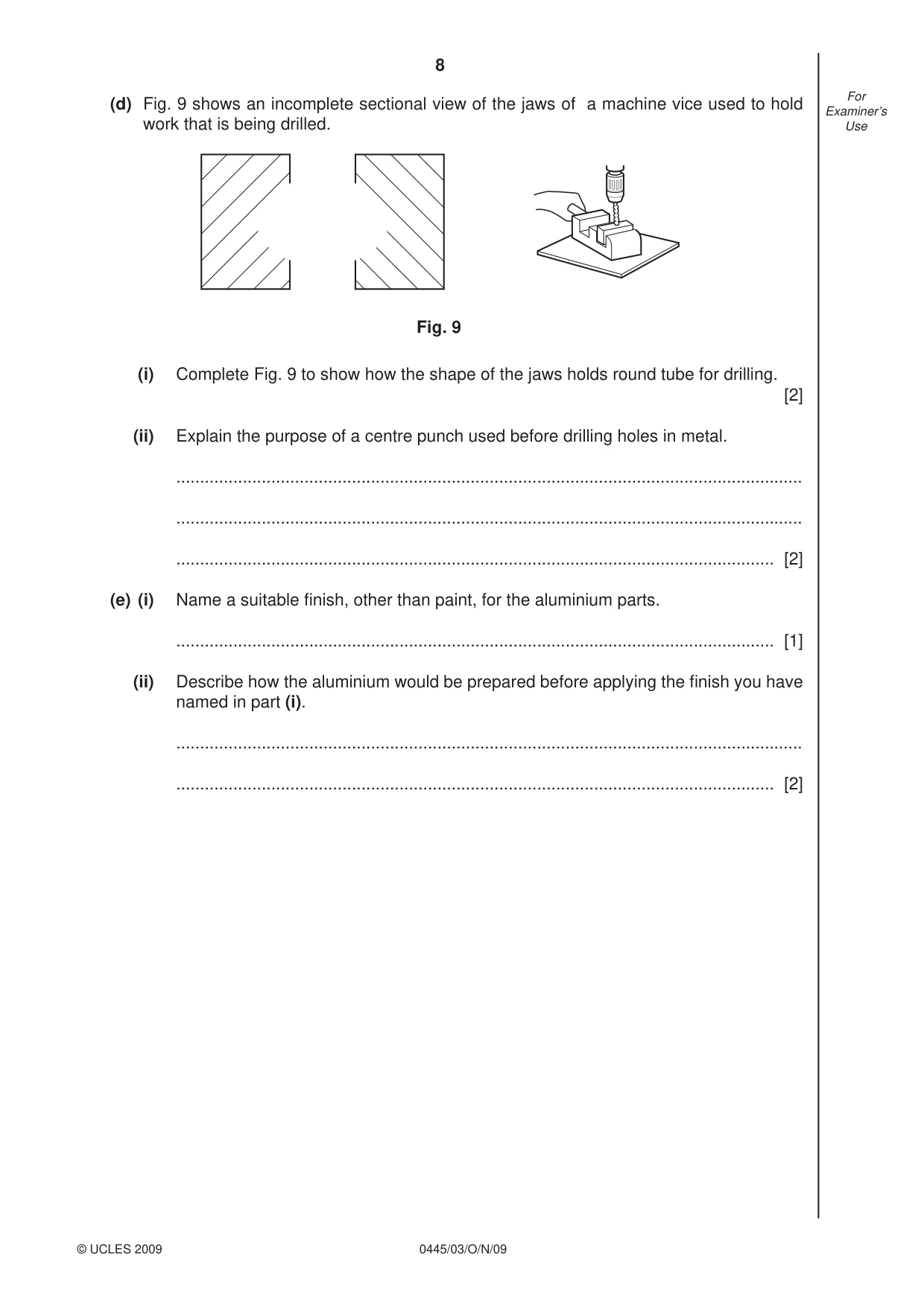
8 0445/03/O/N/09 © UCLES 2009 For Examiner’s Use (d) Fig. 9 shows an incomplete sectional view of the jaws of a machine vice used to hold work that is being drilled. Fig. 9 (i) Complete Fig. 9 to show how the shape of the jaws holds round tube for drilling. [2] (ii) Explain the purpose of a centre punch used before drilling holes in metal. … … … [2] (e) (i) Name a suitable fi nish, other than paint, for the aluminium parts. … [1] (ii) Describe how the aluminium would be prepared before applying the fi nish you have named in part (i). … … [2]
Question paper, page 9
9 0445/03/O/N/09 © UCLES 2009 [Turn over For Examiner’s Use (f) Use sketches and notes to show a modifi cation to the wind chime to enable it to be fi xed to a wall. [4]
Question paper, page 10
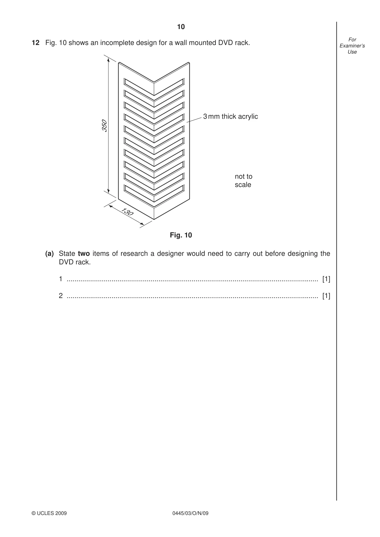
10 0445/03/O/N/09 © UCLES 2009 For Examiner’s Use 12 Fig. 10 shows an incomplete design for a wall mounted DVD rack. 130 350 3 mm thick acrylic not to scale Fig. 10 (a) State two items of research a designer would need to carry out before designing the DVD rack. 1 … [1] 2 … [1]
Question paper, page 11
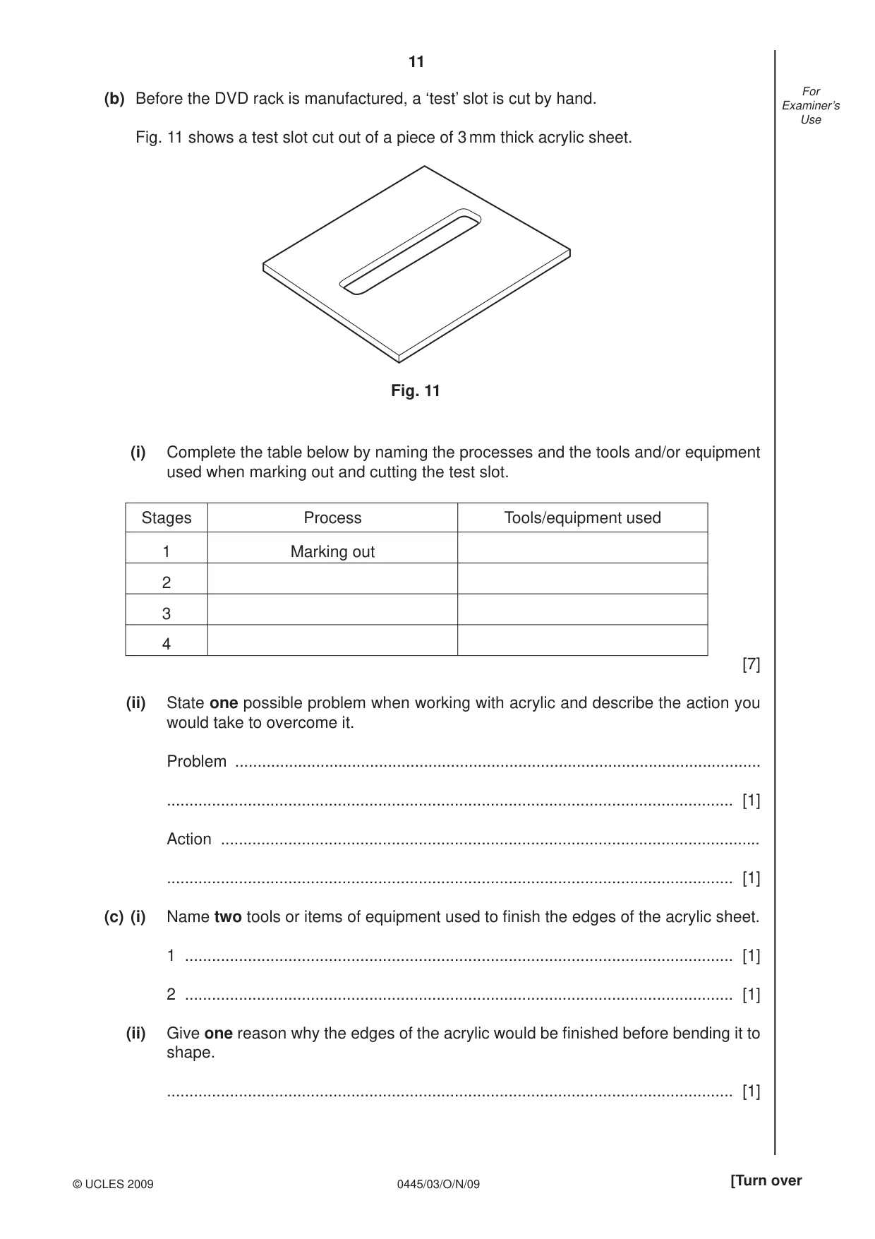
11 0445/03/O/N/09 © UCLES 2009 [Turn over For Examiner’s Use (b) Before the DVD rack is manufactured, a ‘test’ slot is cut by hand. Fig. 11 shows a test slot cut out of a piece of 3 mm thick acrylic sheet. Fig. 11 (i) Complete the table below by naming the processes and the tools and/or equipment used when marking out and cutting the test slot. Stages Process Tools/equipment used 1 Marking out 2 3 4 [7] (ii) State one possible problem when working with acrylic and describe the action you would take to overcome it. Problem … … [1] Action … … [1] (c) (i) Name two tools or items of equipment used to fi nish the edges of the acrylic sheet. 1 … [1] 2 … [1] (ii) Give one reason why the edges of the acrylic would be fi nished before bending it to shape. … [1]
Question paper, page 12
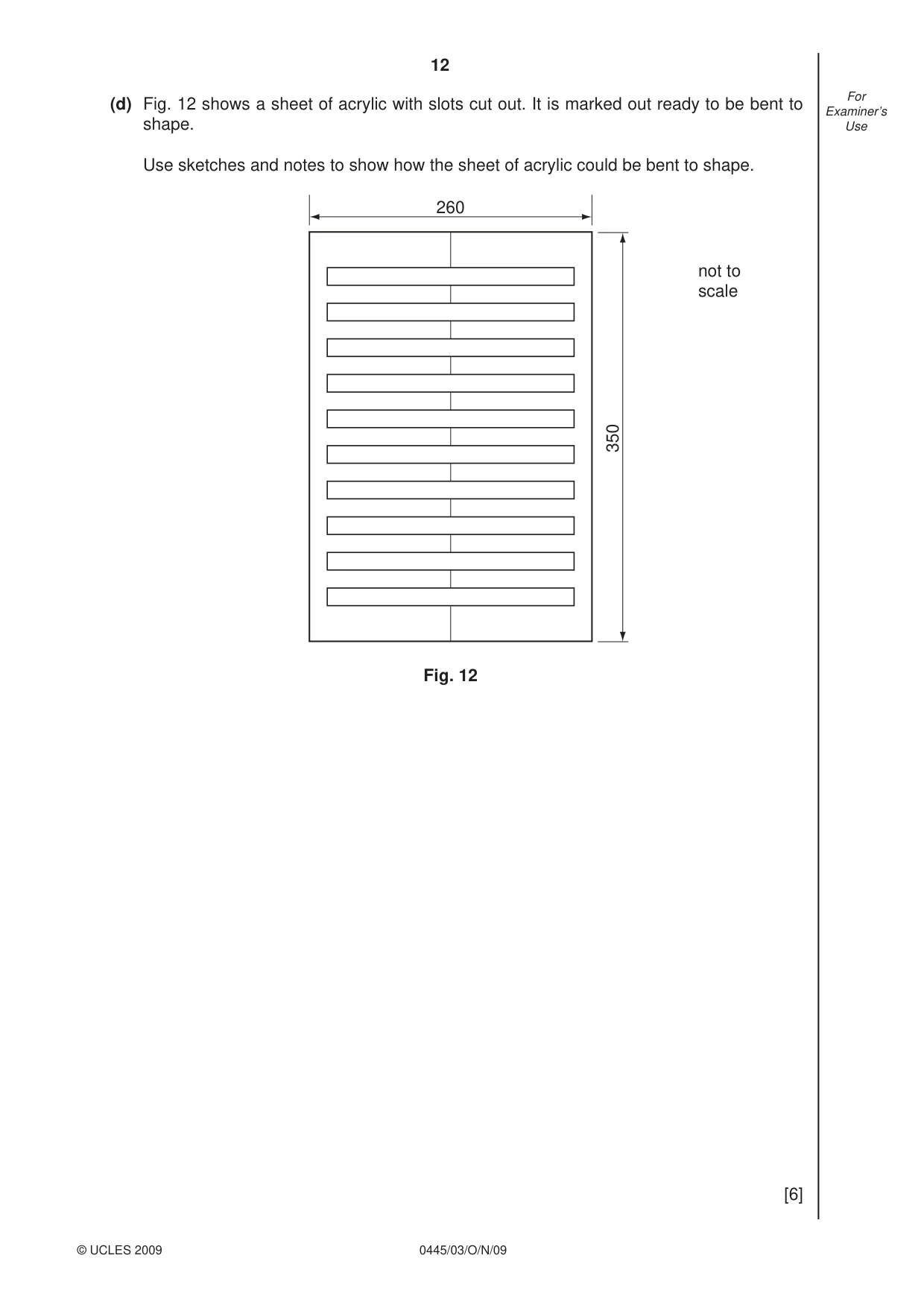
12 0445/03/O/N/09 © UCLES 2009 For Examiner’s Use (d) Fig. 12 shows a sheet of acrylic with slots cut out. It is marked out ready to be bent to shape. Use sketches and notes to show how the sheet of acrylic could be bent to shape. 260 350 not to scale Fig. 12 [6]
Question paper, page 13
13 0445/03/O/N/09 © UCLES 2009 [Turn over For Examiner’s Use (e) The DVD rack shown in Fig. 10 is to be wall mounted. Use sketches and notes to show how the design could be modifi ed so that it could be wall mounted. Include details of any materials, constructions and fi ttings used. [5]
Question paper, page 14
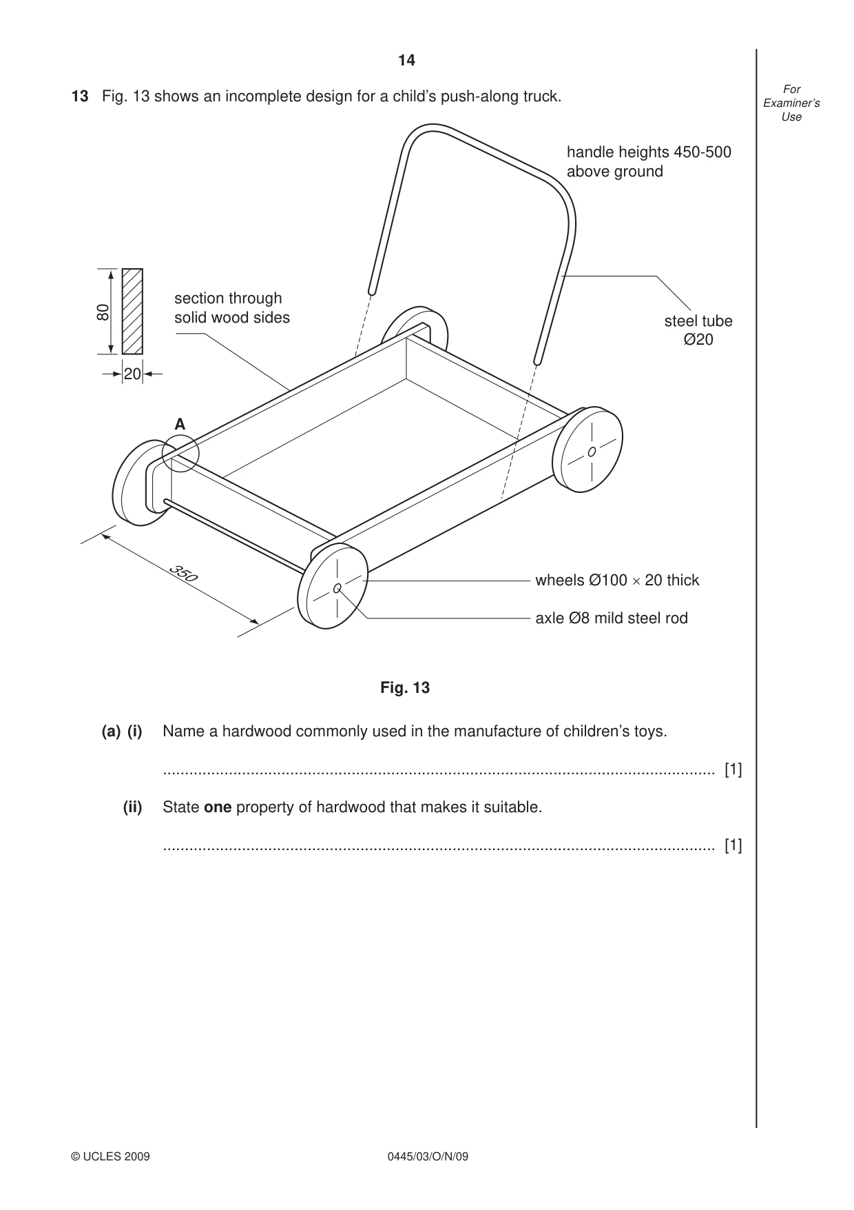
14 0445/03/O/N/09 © UCLES 2009 For Examiner’s Use 13 Fig. 13 shows an incomplete design for a child’s push-along truck. wheels Ø100 × 20 thick steel tube Ø20 axle Ø8 mild steel rod handle heights 450-500 above ground A 20 80 section through solid wood sides 350 Fig. 13 (a) (i) Name a hardwood commonly used in the manufacture of children’s toys. … [1] (ii) State one property of hardwood that makes it suitable. … [1]
Question paper, page 15
15 0445/03/O/N/09 © UCLES 2009 [Turn over For Examiner’s Use (b) Name and sketch two constructions that could be used to join the sides at A. Name … [1] Sketch [3] Name … [1] Sketch [3]
Question paper, page 16
16 0445/03/O/N/09 © UCLES 2009 For Examiner’s Use (c) The handle must be capable of height adjustment and removal. Use sketches and notes to complete the design of the handle to show how it can be: ● fi tted to the sides of the truck; ● adjusted and secured at three different heights; ● easily removed. [6] (d) Use sketches and notes to show how the wheels could be prevented from coming off the axle. Consider the safety of a child using the truck in your method. [3]
Question paper, page 17
17 0445/03/O/N/09 © UCLES 2009 For Examiner’s Use (e) The wheels could be produced on a lathe. Use sketches and notes to show how one wheel could be produced. Include details of the preparation of the wood used for the wheel before it is set up on the lathe. [6]
Question paper, page 20
20 0445/03/O/N/09 Permission to reproduce items where third-party owned material protected by copyright is included has been sought and cleared where possible. Every reasonable effort has been made by the publisher (UCLES) to trace copyright holders, but if any items requiring clearance have unwittingly been included the publisher will be pleased to make amends at the earliest possible opportunity. University of Cambridge International Examinations is part of the Cambridge Assessment Group. Cambridge Assessment is the brand name of University of Cambridge Local Examinations Syndicate (UCLES), which is itself a department of the University of Cambridge. BLANK PAGE
Mark scheme, page 1
UNIVERSITY OF CAMBRIDGE INTERNATIONAL EXAMINATIONS International General Certificate of Secondary Education MARK SCHEME for the October/November 2009 question paper for the guidance of teachers 0445 DESIGN AND TECHNOLOGY 0445/03 Paper 3 (Resistant Materials), maximum raw mark 50 This mark scheme is published as an aid to teachers and candidates, to indicate the requirements of the examination. It shows the basis on which Examiners were instructed to award marks. It does not indicate the details of the discussions that took place at an Examiners’ meeting before marking began, which would have considered the acceptability of alternative answers. Mark schemes must be read in conjunction with the question papers and the report on the examination. • CIE will not enter into discussions or correspondence in connection with these mark schemes. CIE is publishing the mark schemes for the October/November 2009 question papers for most IGCSE, GCE Advanced Level and Advanced Subsidiary Level syllabuses and some Ordinary Level syllabuses. www.XtremePapers.com
Mark scheme, page 2
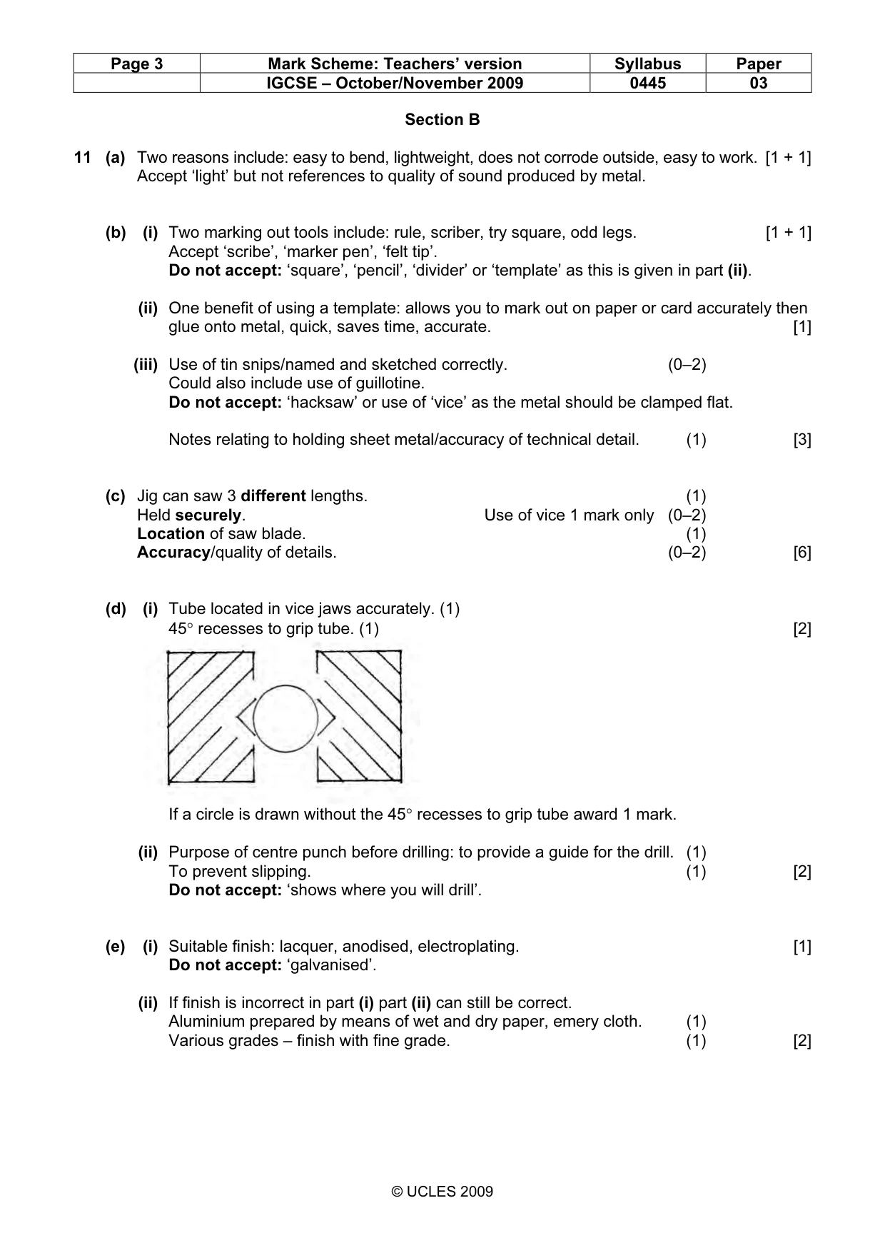
Page 2 Mark Scheme: Teachers’ version Syllabus Paper IGCSE – October/November 2009 0445 03 © UCLES 2009 Section A 1 (a) 1 mark for each cramp shown positioned across ends of frame. If G cramp is shown, award 0 marks. [2] (b) Sash cramps. [1] 2 A Hammer. Ignore any reference to ‘pin’, ‘ball pein’ etc. and award 1 mark. [1] B Scrap wood, waste wood, block of wood, but not ‘former’. [1] C Folding bars, bending irons. [1] 3 Grain must be shown at right angles to next layer. 1 mark if only 2 layers shown. [2] If 3 layers are drawn with grain shown in same direction award 0 marks. 4 Draw filing. [1] No alternative answers. 5 Two methods of planing end grain include: [1 + 1] • plane to middle, stop, plane to middle from opposite end; • position scrapwood at end of wood at plane across; award benefit of doubt to wood positioned at side of that being planed. • shooting board. 6 (a) Odd leg or ‘Jenny’ calipers. Accept ‘calipers’. [1] Used to draw lines on metal or plastic parallel to an edge. [1] Candidates can still achieve 1 mark for correct description even if incorrectly named. [2] (b) Rule shown under foot of calipers with point on required distance. [1] 7 Completed joint 0–3 dependent upon accuracy/clarity. [3] 8 Suitable specific finish for: solid wood table top: polyurethane varnish, varnish, wax polish or cellulose lacquer. Do not accept French polish. [1] wooden chopping board for vegetables: olive oil, linseed oil or no finish. Do not accept ‘glasspaper’ or references to covering with a plastic laminate. [1] 9 Soft drinks bottle: extrusion blow moulding, blow moulding. Do not accept ‘blow forming’. [1] Canoe: GRP, moulding, lay up. [1] Bucket: injection moulding. [1] 10 A Tool post [1] B Bed [1] C Lead screw [1] There are no alternative correct answers to these 3 terms.
Mark scheme, page 3
Page 3 Mark Scheme: Teachers’ version Syllabus Paper IGCSE – October/November 2009 0445 03 © UCLES 2009 Section B 11 (a) Two reasons include: easy to bend, lightweight, does not corrode outside, easy to work. [1 + 1] Accept ‘light’ but not references to quality of sound produced by metal. (b) (i) Two marking out tools include: rule, scriber, try square, odd legs. [1 + 1] Accept ‘scribe’, ‘marker pen’, ‘felt tip’. Do not accept: ‘square’, ‘pencil’, ‘divider’ or ‘template’ as this is given in part (ii). (ii) One benefit of using a template: allows you to mark out on paper or card accurately then glue onto metal, quick, saves time, accurate. [1] (iii) Use of tin snips/named and sketched correctly. (0–2) Could also include use of guillotine. Do not accept: ‘hacksaw’ or use of ‘vice’ as the metal should be clamped flat. Notes relating to holding sheet metal/accuracy of technical detail. (1) [3] (c) Jig can saw 3 different lengths. (1) Held securely. Use of vice 1 mark only (0–2) Location of saw blade. (1) Accuracy/quality of details. (0–2) [6] (d) (i) Tube located in vice jaws accurately. (1) 45° recesses to grip tube. (1) [2] If a circle is drawn without the 45° recesses to grip tube award 1 mark. (ii) Purpose of centre punch before drilling: to provide a guide for the drill. (1) To prevent slipping. (1) [2] Do not accept: ‘shows where you will drill’. (e) (i) Suitable finish: lacquer, anodised, electroplating. [1] Do not accept: ‘galvanised’. (ii) If finish is incorrect in part (i) part (ii) can still be correct. Aluminium prepared by means of wet and dry paper, emery cloth. (1) Various grades – finish with fine grade. (1) [2]
Mark scheme, page 4
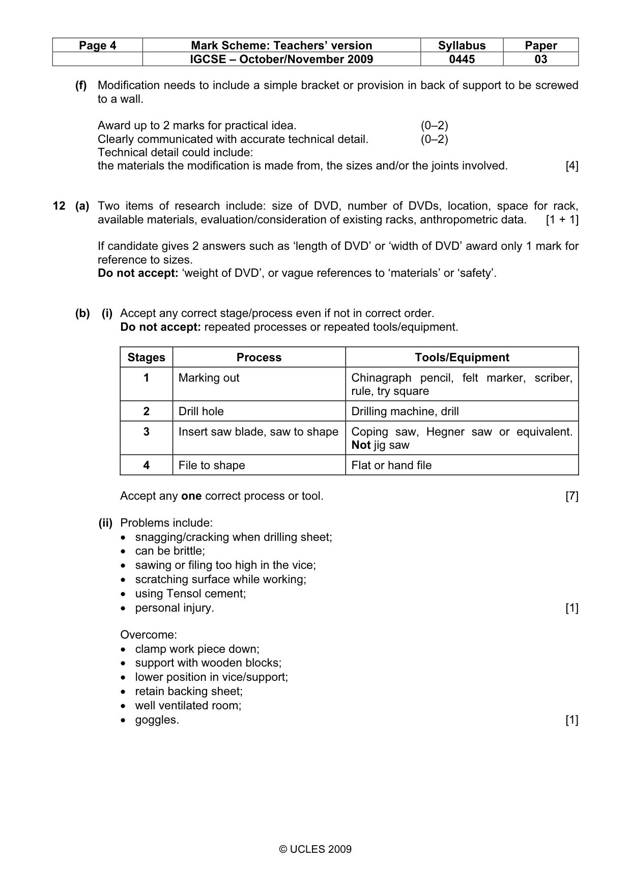
Page 4 Mark Scheme: Teachers’ version Syllabus Paper IGCSE – October/November 2009 0445 03 © UCLES 2009 (f) Modification needs to include a simple bracket or provision in back of support to be screwed to a wall. Award up to 2 marks for practical idea. (0–2) Clearly communicated with accurate technical detail. (0–2) Technical detail could include: the materials the modification is made from, the sizes and/or the joints involved. [4] 12 (a) Two items of research include: size of DVD, number of DVDs, location, space for rack, available materials, evaluation/consideration of existing racks, anthropometric data. [1 + 1] If candidate gives 2 answers such as ‘length of DVD’ or ‘width of DVD’ award only 1 mark for reference to sizes. Do not accept: ‘weight of DVD’, or vague references to ‘materials’ or ‘safety’. (b) (i) Accept any correct stage/process even if not in correct order. Do not accept: repeated processes or repeated tools/equipment. Stages Process Tools/Equipment 1 Marking out Chinagraph pencil, felt marker, scriber, rule, try square 2 Drill hole Drilling machine, drill 3 Insert saw blade, saw to shape Coping saw, Hegner saw or equivalent. Not jig saw 4 File to shape Flat or hand file Accept any one correct process or tool. [7] (ii) Problems include: • snagging/cracking when drilling sheet; • can be brittle; • sawing or filing too high in the vice; • scratching surface while working; • using Tensol cement; • personal injury. [1] Overcome: • clamp work piece down; • support with wooden blocks; • lower position in vice/support; • retain backing sheet; • well ventilated room; • goggles. [1]
Mark scheme, page 5
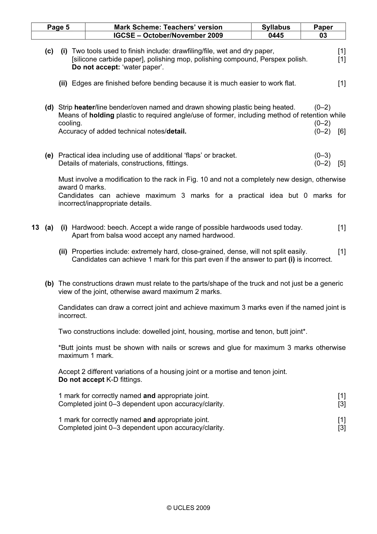
Page 5 Mark Scheme: Teachers’ version Syllabus Paper IGCSE – October/November 2009 0445 03 © UCLES 2009 (c) (i) Two tools used to finish include: drawfiling/file, wet and dry paper, [1] [silicone carbide paper], polishing mop, polishing compound, Perspex polish. [1] Do not accept: ‘water paper’. (ii) Edges are finished before bending because it is much easier to work flat. [1] (d) Strip heater/line bender/oven named and drawn showing plastic being heated. (0–2) Means of holding plastic to required angle/use of former, including method of retention while cooling. (0–2) Accuracy of added technical notes/detail. (0–2) [6] (e) Practical idea including use of additional ‘flaps’ or bracket. (0–3) Details of materials, constructions, fittings. (0–2) [5] Must involve a modification to the rack in Fig. 10 and not a completely new design, otherwise award 0 marks. Candidates can achieve maximum 3 marks for a practical idea but 0 marks for incorrect/inappropriate details. 13 (a) (i) Hardwood: beech. Accept a wide range of possible hardwoods used today. [1] Apart from balsa wood accept any named hardwood. (ii) Properties include: extremely hard, close-grained, dense, will not split easily. [1] Candidates can achieve 1 mark for this part even if the answer to part (i) is incorrect. (b) The constructions drawn must relate to the parts/shape of the truck and not just be a generic view of the joint, otherwise award maximum 2 marks. Candidates can draw a correct joint and achieve maximum 3 marks even if the named joint is incorrect. Two constructions include: dowelled joint, housing, mortise and tenon, butt joint*. *Butt joints must be shown with nails or screws and glue for maximum 3 marks otherwise maximum 1 mark. Accept 2 different variations of a housing joint or a mortise and tenon joint. Do not accept K-D fittings. 1 mark for correctly named and appropriate joint. [1] Completed joint 0–3 dependent upon accuracy/clarity. [3] 1 mark for correctly named and appropriate joint. [1] Completed joint 0–3 dependent upon accuracy/clarity. [3]
Mark scheme, page 6
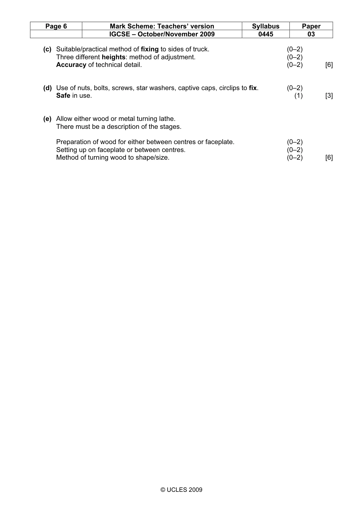
Page 6 Mark Scheme: Teachers’ version Syllabus Paper IGCSE – October/November 2009 0445 03 © UCLES 2009 (c) Suitable/practical method of fixing to sides of truck. (0–2) Three different heights: method of adjustment. (0–2) Accuracy of technical detail. (0–2) [6] (d) Use of nuts, bolts, screws, star washers, captive caps, circlips to fix. (0–2) Safe in use. (1) [3] (e) Allow either wood or metal turning lathe. There must be a description of the stages. Preparation of wood for either between centres or faceplate. (0–2) Setting up on faceplate or between centres. (0–2) Method of turning wood to shape/size. (0–2) [6]
What you needed in this session
Cambridge’s own grade thresholds for 2009 Oct/Nov, Paper 3 · Variant 1. A higher threshold means an easier paper — the bar moves with how the cohort did.