Cambridge IGCSE Design and Technology 0445 — 2009 May/June Paper 3 · Variant 1
0445/31/M/J/09 · 50 marks · ≈56 min
The question paper and its mark scheme, free to read here and free to download. This is Cambridge’s own paper, exactly as it was sat.
Question paper20 pages


Mark scheme6 pages
Answers below. Sit the paper first if you are practising.
Paper as text
Question paper, page 1
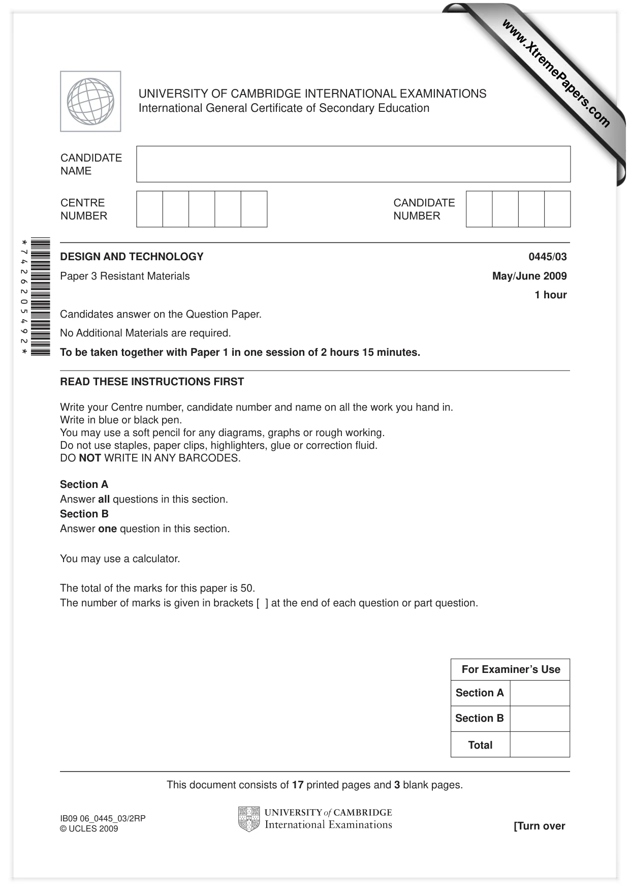
READ THESE INSTRUCTIONS FIRST Write your Centre number, candidate number and name on all the work you hand in. Write in blue or black pen. You may use a soft pencil for any diagrams, graphs or rough working. Do not use staples, paper clips, highlighters, glue or correction fl uid. DO NOT WRITE IN ANY BARCODES. Section A Answer all questions in this section. Section B Answer one question in this section. You may use a calculator. The total of the marks for this paper is 50. The number of marks is given in brackets [ ] at the end of each question or part question. DESIGN AND TECHNOLOGY 0445/03 Paper 3 Resistant Materials May/June 2009 1 hour Candidates answer on the Question Paper. No Additional Materials are required. To be taken together with Paper 1 in one session of 2 hours 15 minutes. UNIVERSITY OF CAMBRIDGE INTERNATIONAL EXAMINATIONS International General Certifi cate of Secondary Education This document consists of 17 printed pages and 3 blank pages. [Turn over IB09 06_0445_03/2RP © UCLES 2009 *7426205492* For Examiner’s Use Total Section A Section B www.XtremePapers.com
Question paper, page 2
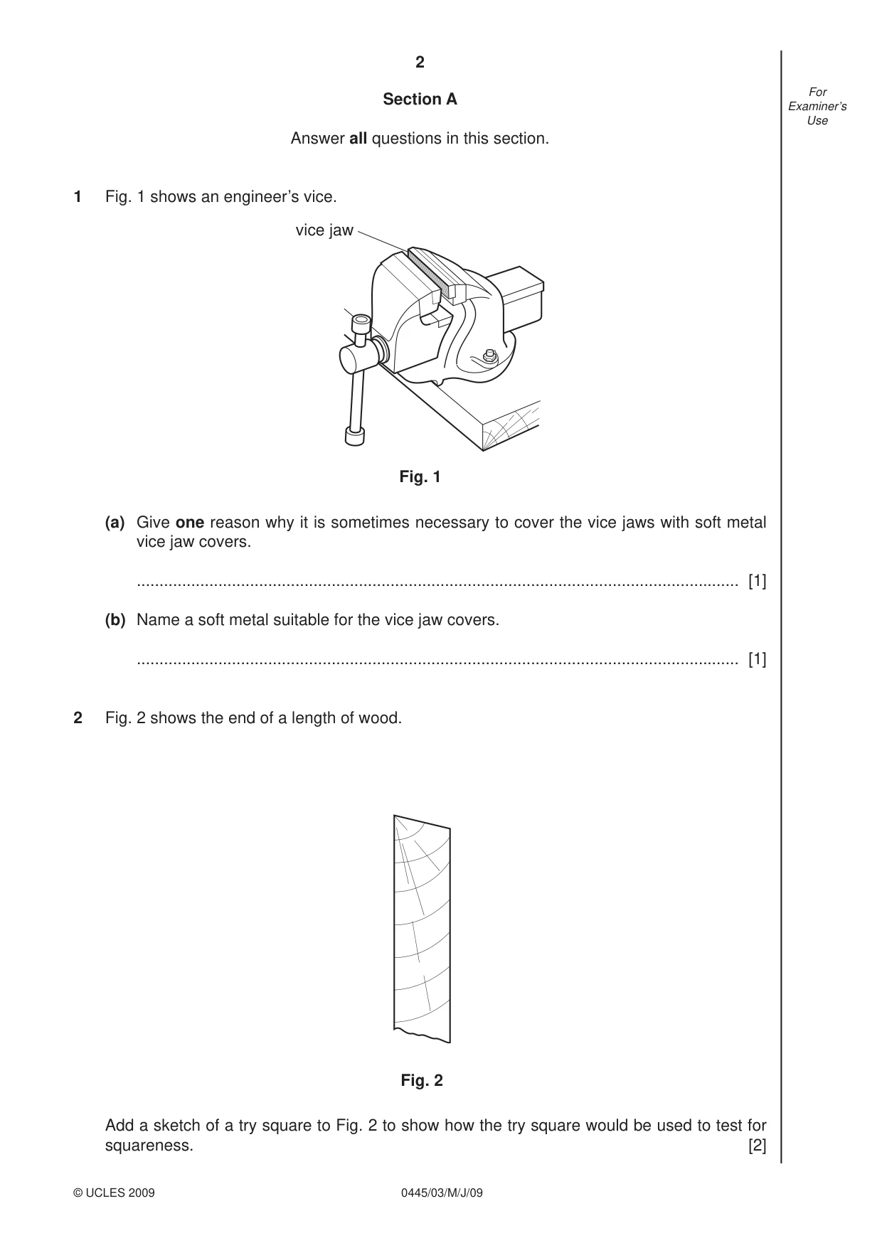
2 0445/03/M/J/09 © UCLES 2009 For Examiner’s Use Section A Answer all questions in this section. 1 Fig. 1 shows an engineer’s vice. vice jaw Fig. 1 (a) Give one reason why it is sometimes necessary to cover the vice jaws with soft metal vice jaw covers. … [1] (b) Name a soft metal suitable for the vice jaw covers. … [1] 2 Fig. 2 shows the end of a length of wood. Fig. 2 Add a sketch of a try square to Fig. 2 to show how the try square would be used to test for squareness. [2]
Question paper, page 3
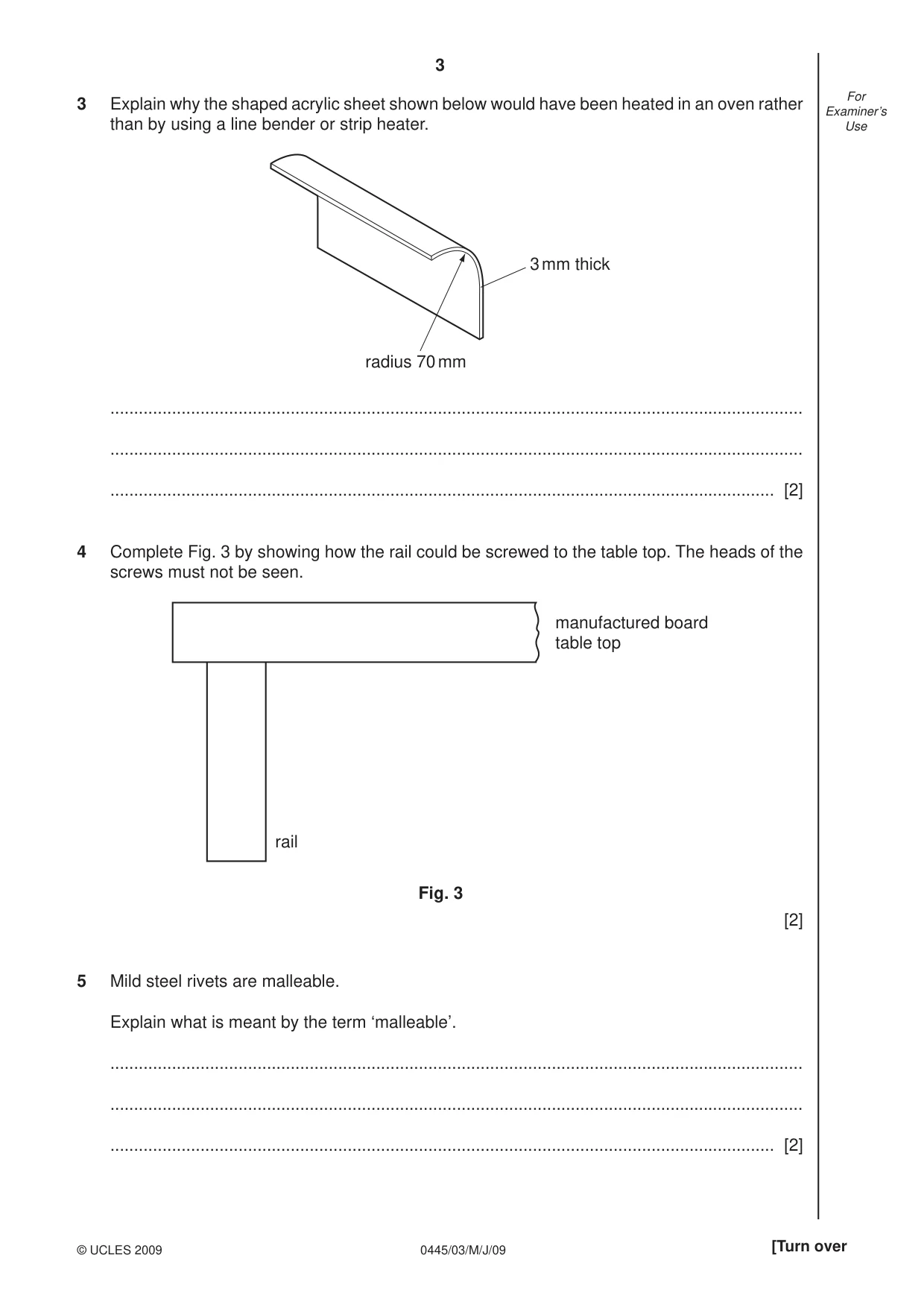
3 0445/03/M/J/09 © UCLES 2009 [Turn over For Examiner’s Use 3 Explain why the shaped acrylic sheet shown below would have been heated in an oven rather than by using a line bender or strip heater. radius 70 mm 3 mm thick … … … [2] 4 Complete Fig. 3 by showing how the rail could be screwed to the table top. The heads of the screws must not be seen. manufactured board table top rail Fig. 3 [2] 5 Mild steel rivets are malleable. Explain what is meant by the term ‘malleable’. … … … [2]
Question paper, page 4
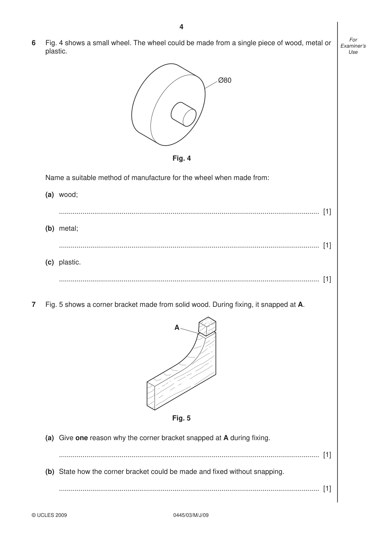
4 0445/03/M/J/09 © UCLES 2009 For Examiner’s Use 6 Fig. 4 shows a small wheel. The wheel could be made from a single piece of wood, metal or plastic. Ø80 Fig. 4 Name a suitable method of manufacture for the wheel when made from: (a) wood; … [1] (b) metal; … [1] (c) plastic. … [1] 7 Fig. 5 shows a corner bracket made from solid wood. During fi xing, it snapped at A. A Fig. 5 (a) Give one reason why the corner bracket snapped at A during fi xing. … [1] (b) State how the corner bracket could be made and fi xed without snapping. … [1]
Question paper, page 5
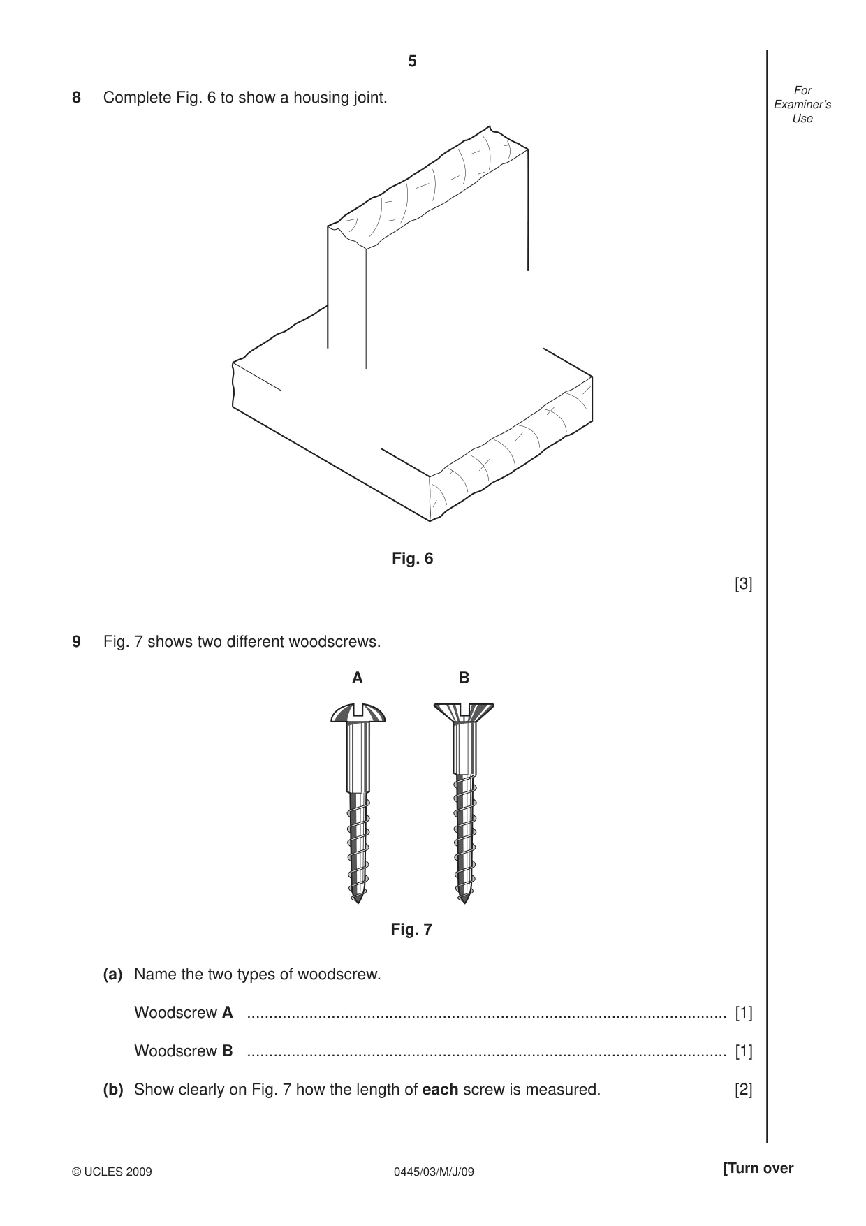
5 0445/03/M/J/09 © UCLES 2009 [Turn over For Examiner’s Use 8 Complete Fig. 6 to show a housing joint. Fig. 6 [3] 9 Fig. 7 shows two different woodscrews. A B Fig. 7 (a) Name the two types of woodscrew. Woodscrew A … [1] Woodscrew B … [1] (b) Show clearly on Fig. 7 how the length of each screw is measured. [2]
Question paper, page 6
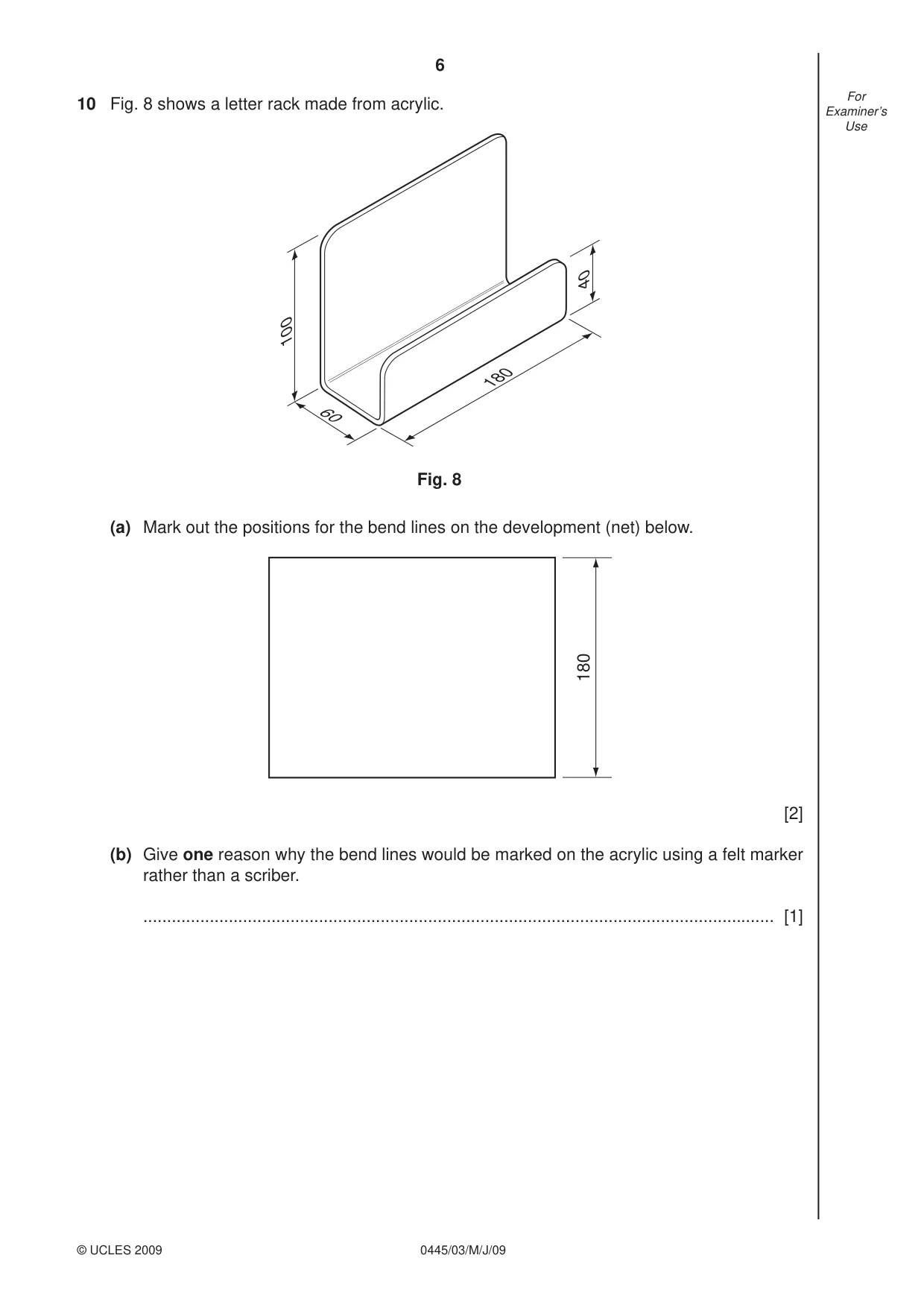
6 0445/03/M/J/09 © UCLES 2009 For Examiner’s Use 10 Fig. 8 shows a letter rack made from acrylic. 60 180 40 100 Fig. 8 (a) Mark out the positions for the bend lines on the development (net) below. 180 [2] (b) Give one reason why the bend lines would be marked on the acrylic using a felt marker rather than a scriber. … [1]
Question paper, page 7
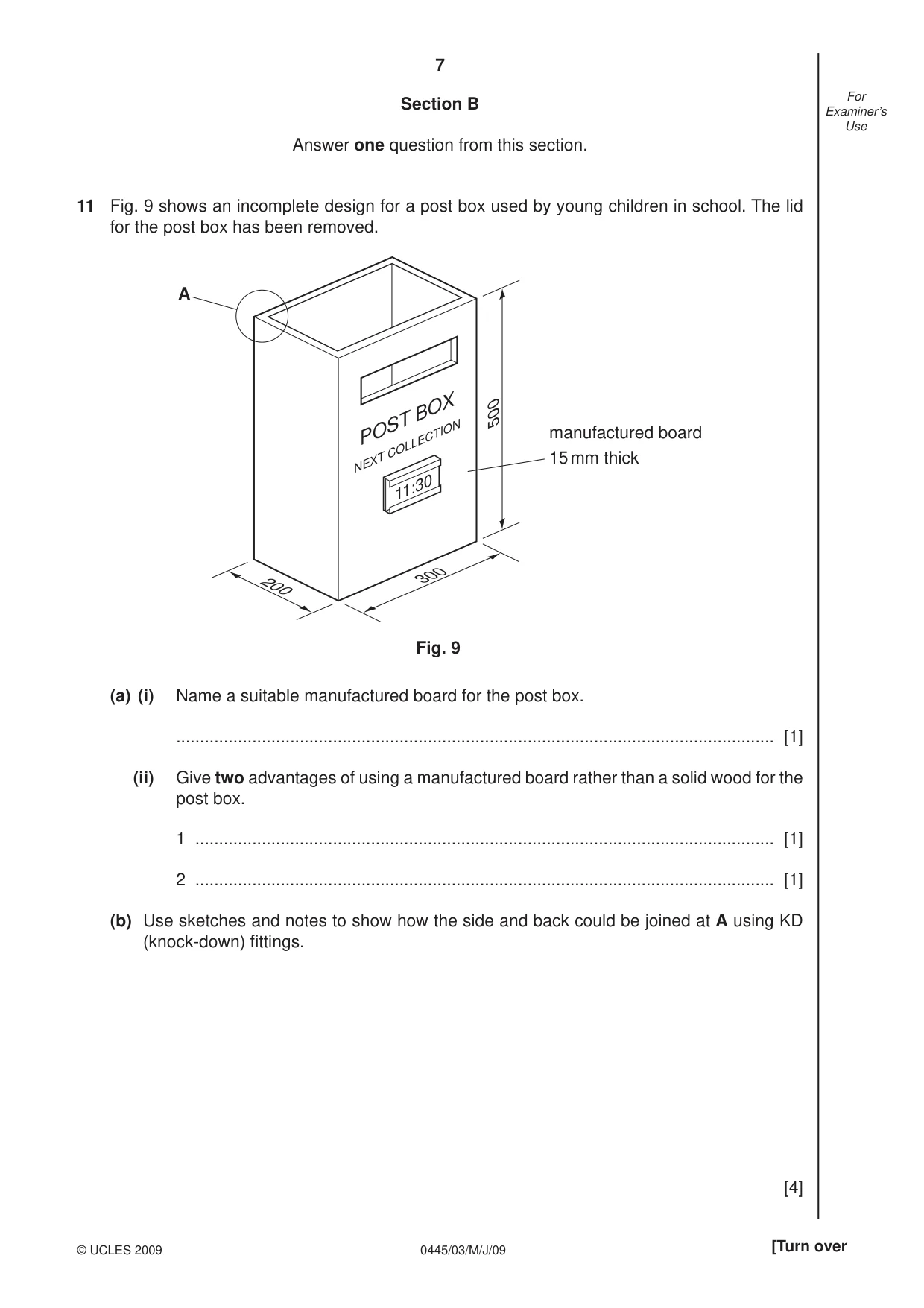
7 0445/03/M/J/09 © UCLES 2009 [Turn over For Examiner’s Use Section B Answer one question from this section. 11 Fig. 9 shows an incomplete design for a post box used by young children in school. The lid for the post box has been removed. 500 POST BOX NEXT COLLECTION 11:30 300 200 A manufactured board 15 mm thick Fig. 9 (a) (i) Name a suitable manufactured board for the post box. … [1] (ii) Give two advantages of using a manufactured board rather than a solid wood for the post box. 1 … [1] 2 … [1] (b) Use sketches and notes to show how the side and back could be joined at A using KD (knock-down) fi ttings. [4]
Question paper, page 8
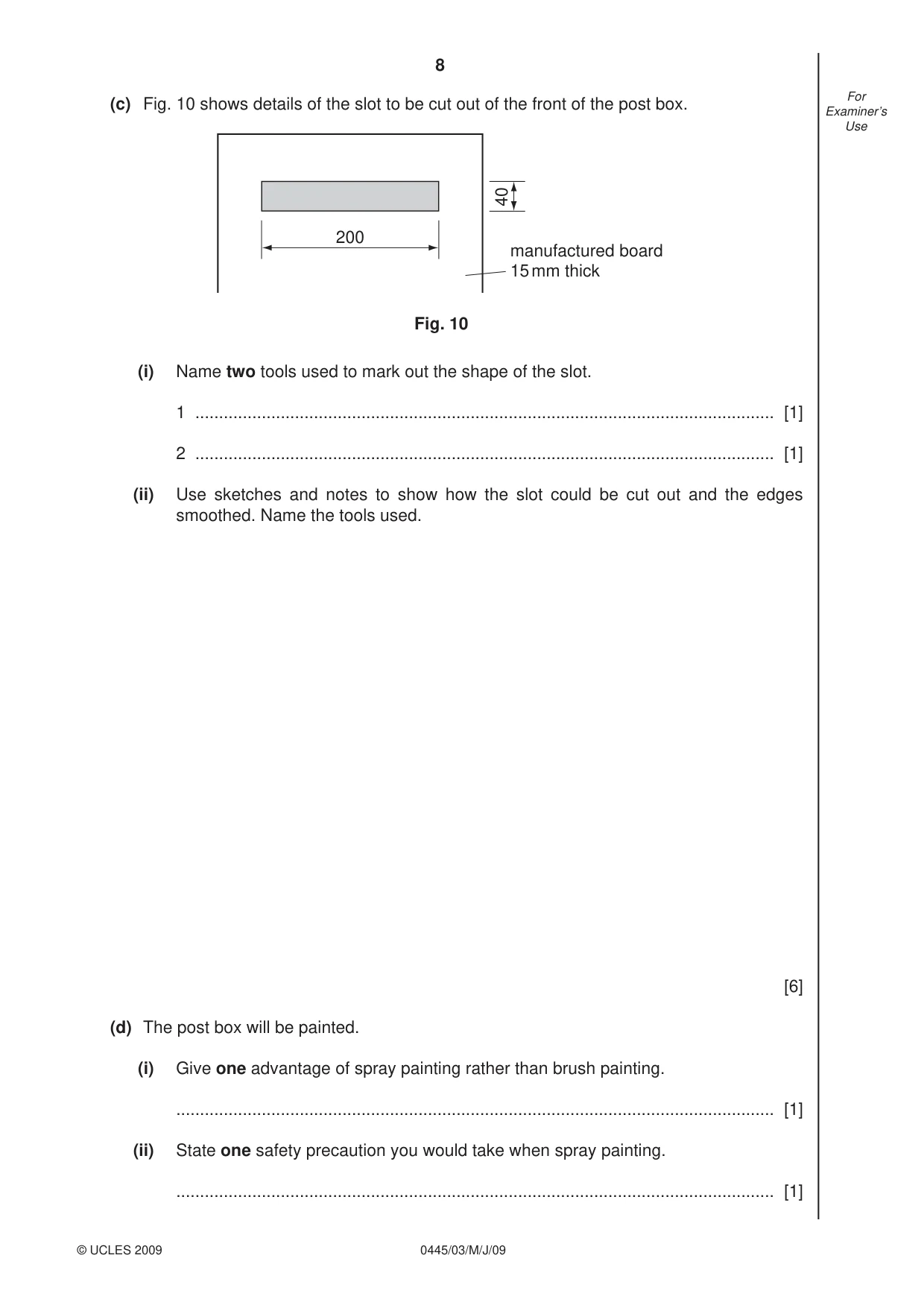
8 0445/03/M/J/09 © UCLES 2009 For Examiner’s Use (c) Fig. 10 shows details of the slot to be cut out of the front of the post box. 200 40 manufactured board 15 mm thick Fig. 10 (i) Name two tools used to mark out the shape of the slot. 1 … [1] 2 … [1] (ii) Use sketches and notes to show how the slot could be cut out and the edges smoothed. Name the tools used. [6] (d) The post box will be painted. (i) Give one advantage of spray painting rather than brush painting. … [1] (ii) State one safety precaution you would take when spray painting. … [1]
Question paper, page 9
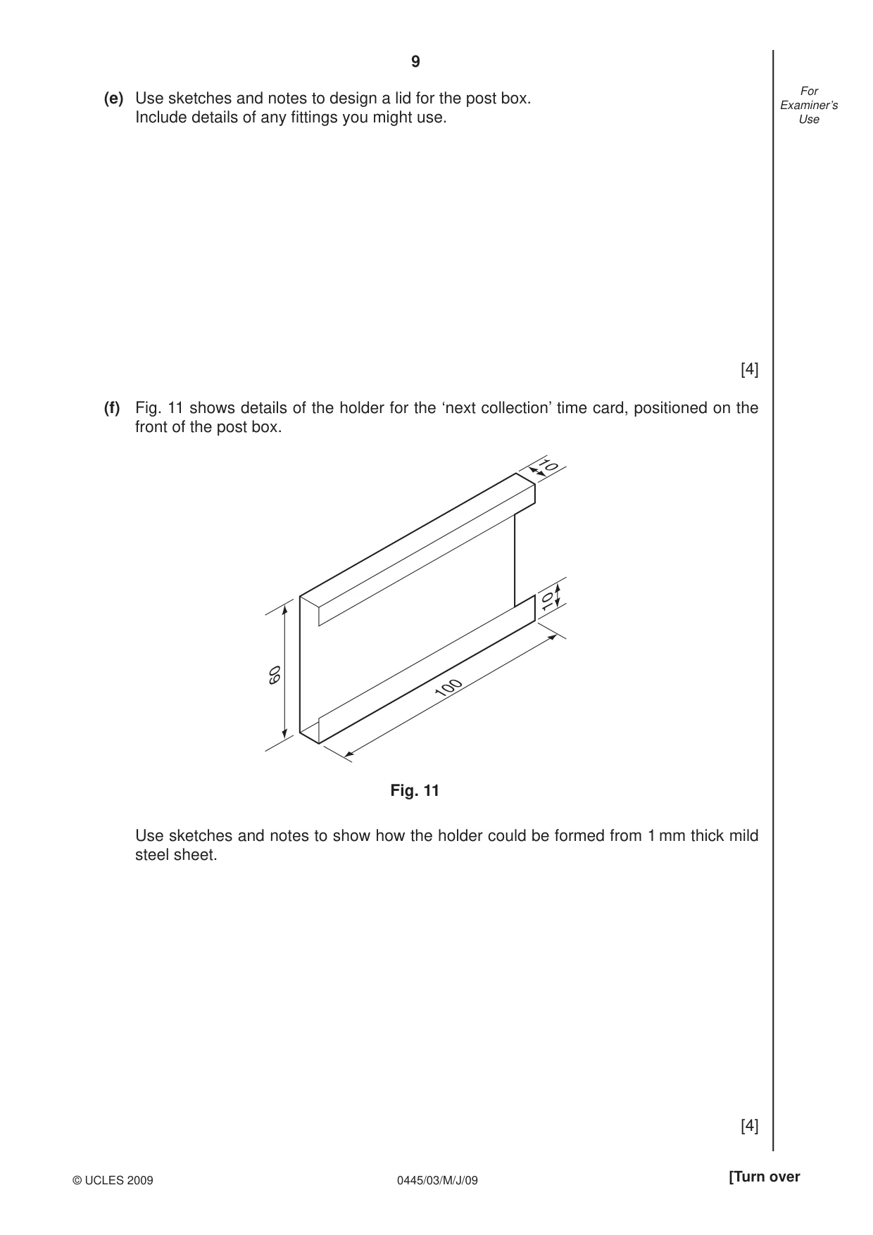
9 0445/03/M/J/09 © UCLES 2009 [Turn over For Examiner’s Use (e) Use sketches and notes to design a lid for the post box. Include details of any fi ttings you might use. [4] (f) Fig. 11 shows details of the holder for the ‘next collection’ time card, positioned on the front of the post box. 10 100 10 60 Fig. 11 Use sketches and notes to show how the holder could be formed from 1 mm thick mild steel sheet. [4]
Question paper, page 10
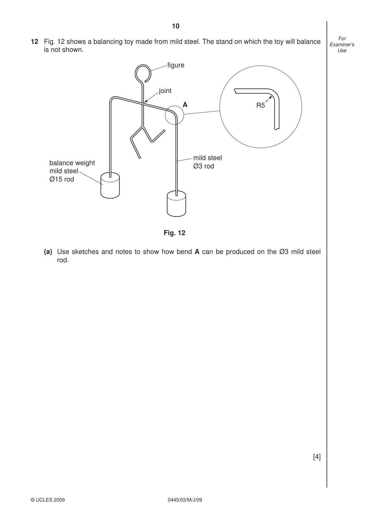
10 0445/03/M/J/09 © UCLES 2009 For Examiner’s Use 12 Fig. 12 shows a balancing toy made from mild steel. The stand on which the toy will balance is not shown. balance weight mild steel Ø15 rod mild steel Ø3 rod figure joint Fig. 12 R5 A (a) Use sketches and notes to show how bend A can be produced on the Ø3 mild steel rod. [4]
Question paper, page 11
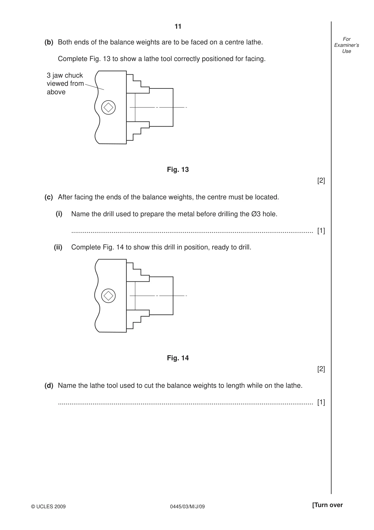
11 0445/03/M/J/09 © UCLES 2009 [Turn over For Examiner’s Use (b) Both ends of the balance weights are to be faced on a centre lathe. Complete Fig. 13 to show a lathe tool correctly positioned for facing. 3 jaw chuck viewed from above Fig. 13 [2] (c) After facing the ends of the balance weights, the centre must be located. (i) Name the drill used to prepare the metal before drilling the Ø3 hole. … [1] (ii) Complete Fig. 14 to show this drill in position, ready to drill. Fig. 14 [2] (d) Name the lathe tool used to cut the balance weights to length while on the lathe. … [1]
Question paper, page 12
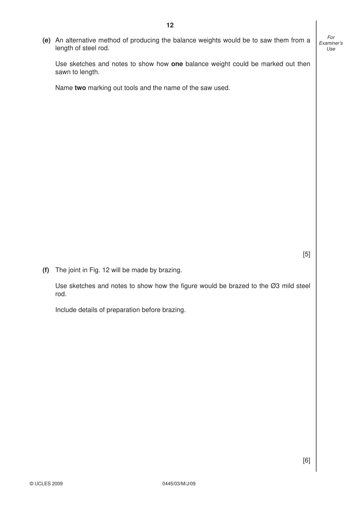
12 0445/03/M/J/09 © UCLES 2009 For Examiner’s Use (e) An alternative method of producing the balance weights would be to saw them from a length of steel rod. Use sketches and notes to show how one balance weight could be marked out then sawn to length. Name two marking out tools and the name of the saw used. [5] (f) The joint in Fig. 12 will be made by brazing. Use sketches and notes to show how the fi gure would be brazed to the Ø3 mild steel rod. Include details of preparation before brazing. [6]
Question paper, page 13
13 0445/03/M/J/09 © UCLES 2009 [Turn over For Examiner’s Use (g) An epoxy resin adhesive could be used to join the balance weights to the mild steel rod. Use sketches and notes to show how the epoxy resin adhesive would be prepared and how the balance weights are held securely while the adhesive sets. [4]
Question paper, page 14
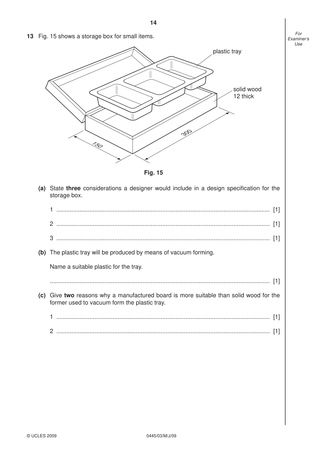
14 0445/03/M/J/09 © UCLES 2009 For Examiner’s Use 13 Fig. 15 shows a storage box for small items. plastic tray solid wood 12 thick Fig. 15 150 300 (a) State three considerations a designer would include in a design specifi cation for the storage box. 1 … [1] 2 … [1] 3 … [1] (b) The plastic tray will be produced by means of vacuum forming. Name a suitable plastic for the tray. … [1] (c) Give two reasons why a manufactured board is more suitable than solid wood for the former used to vacuum form the plastic tray. 1 … [1] 2 … [1]
Question paper, page 15
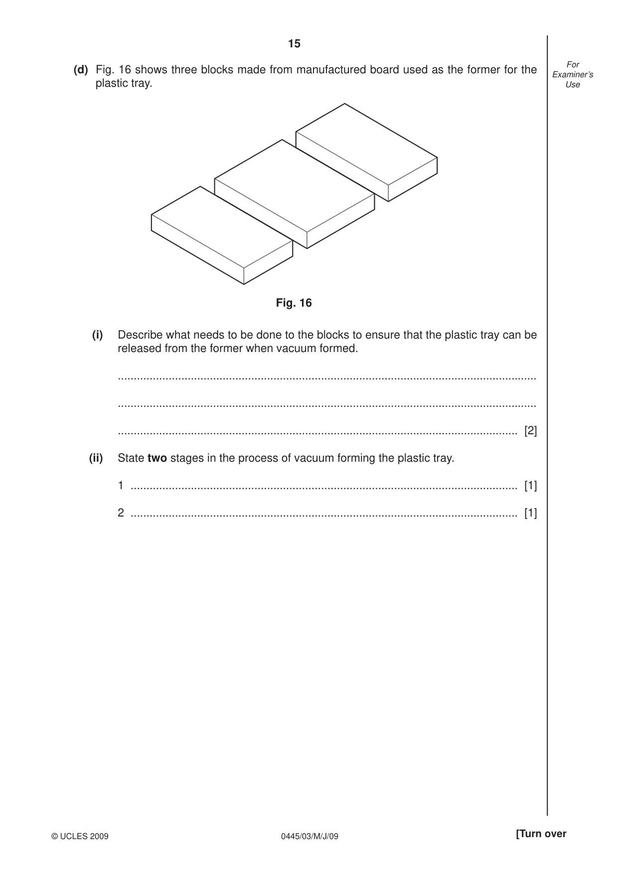
15 0445/03/M/J/09 © UCLES 2009 [Turn over For Examiner’s Use (d) Fig. 16 shows three blocks made from manufactured board used as the former for the plastic tray. Fig. 16 (i) Describe what needs to be done to the blocks to ensure that the plastic tray can be released from the former when vacuum formed. … … … [2] (ii) State two stages in the process of vacuum forming the plastic tray. 1 … [1] 2 … [1]
Question paper, page 16
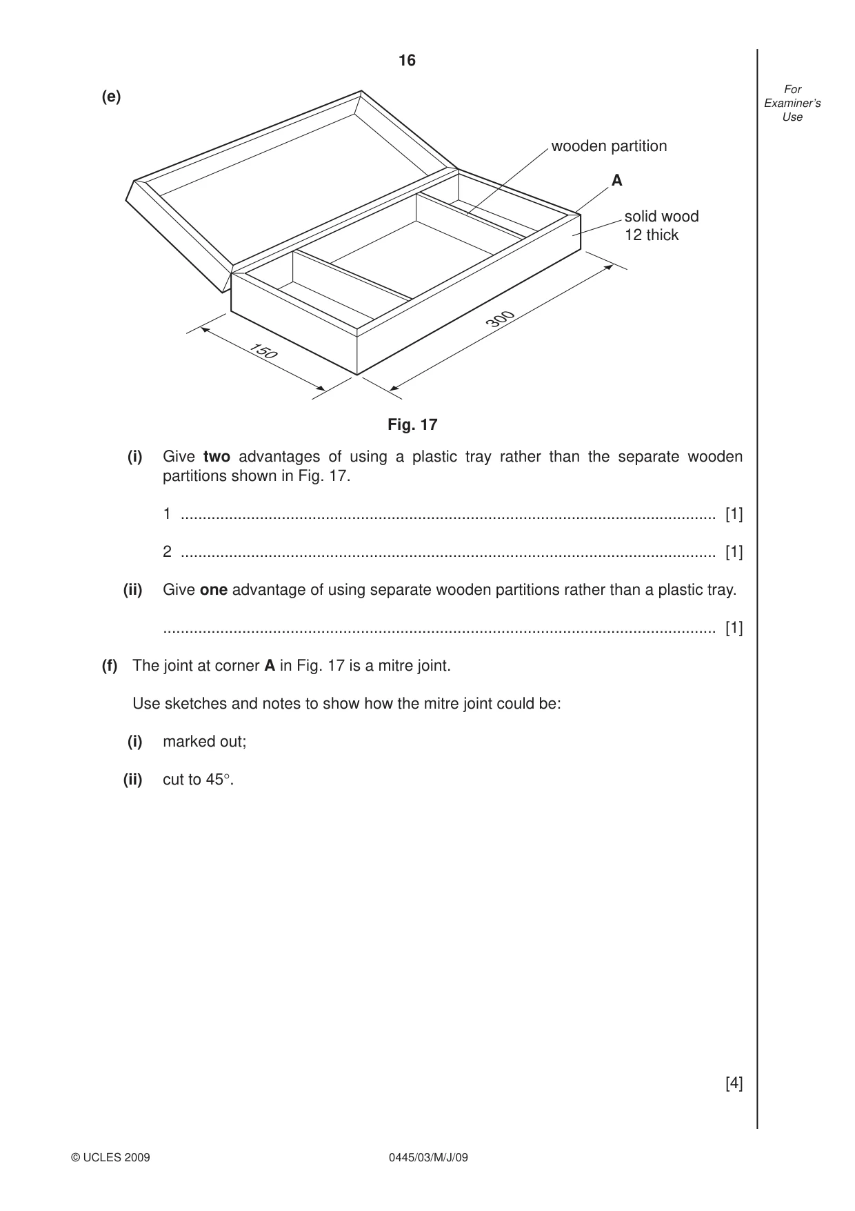
16 0445/03/M/J/09 © UCLES 2009 For Examiner’s Use (e) (i) Give two advantages of using a plastic tray rather than the separate wooden partitions shown in Fig. 17. 1 … [1] 2 … [1] (ii) Give one advantage of using separate wooden partitions rather than a plastic tray. … [1] (f) The joint at corner A in Fig. 17 is a mitre joint. Use sketches and notes to show how the mitre joint could be: (i) marked out; (ii) cut to 45°. [4] solid wood 12 thick Fig. 17 150 300 wooden partition A
Question paper, page 17
17 0445/03/M/J/09 © UCLES 2009 For Examiner’s Use (g) Use sketches and notes to show how a 4 mm thick manufactured board base could be fi tted to the box. The edges of the base must not be seen. [4] (h) Sketch and name a suitable catch that could be used to secure the lid of the box when closed. [4]
Question paper, page 20
20 0445/03/M/J/09 Permission to reproduce items where third-party owned material protected by copyright is included has been sought and cleared where possible. Every reasonable effort has been made by the publisher (UCLES) to trace copyright holders, but if any items requiring clearance have unwittingly been included the publisher will be pleased to make amends at the earliest possible opportunity. University of Cambridge International Examinations is part of the Cambridge Assessment Group. Cambridge Assessment is the brand name of University of Cambridge Local Examinations Syndicate (UCLES), which is itself a department of the University of Cambridge. BLANK PAGE
Mark scheme, page 1
UNIVERSITY OF CAMBRIDGE INTERNATIONAL EXAMINATIONS International General Certificate of Secondary Education MARK SCHEME for the May/June 2009 question paper for the guidance of teachers 0445 DESIGN AND TECHNOLOGY 0445/03 Paper 3 (Resistant Materials), maximum raw mark 50 This mark scheme is published as an aid to teachers and candidates, to indicate the requirements of the examination. It shows the basis on which Examiners were instructed to award marks. It does not indicate the details of the discussions that took place at an Examiners’ meeting before marking began, which would have considered the acceptability of alternative answers. Mark schemes must be read in conjunction with the question papers and the report on the examination. • CIE will not enter into discussions or correspondence in connection with these mark schemes. CIE is publishing the mark schemes for the May/June 2009 question papers for most IGCSE, GCE Advanced Level and Advanced Subsidiary Level syllabuses and some Ordinary Level syllabuses. www.XtremePapers.com
Mark scheme, page 2
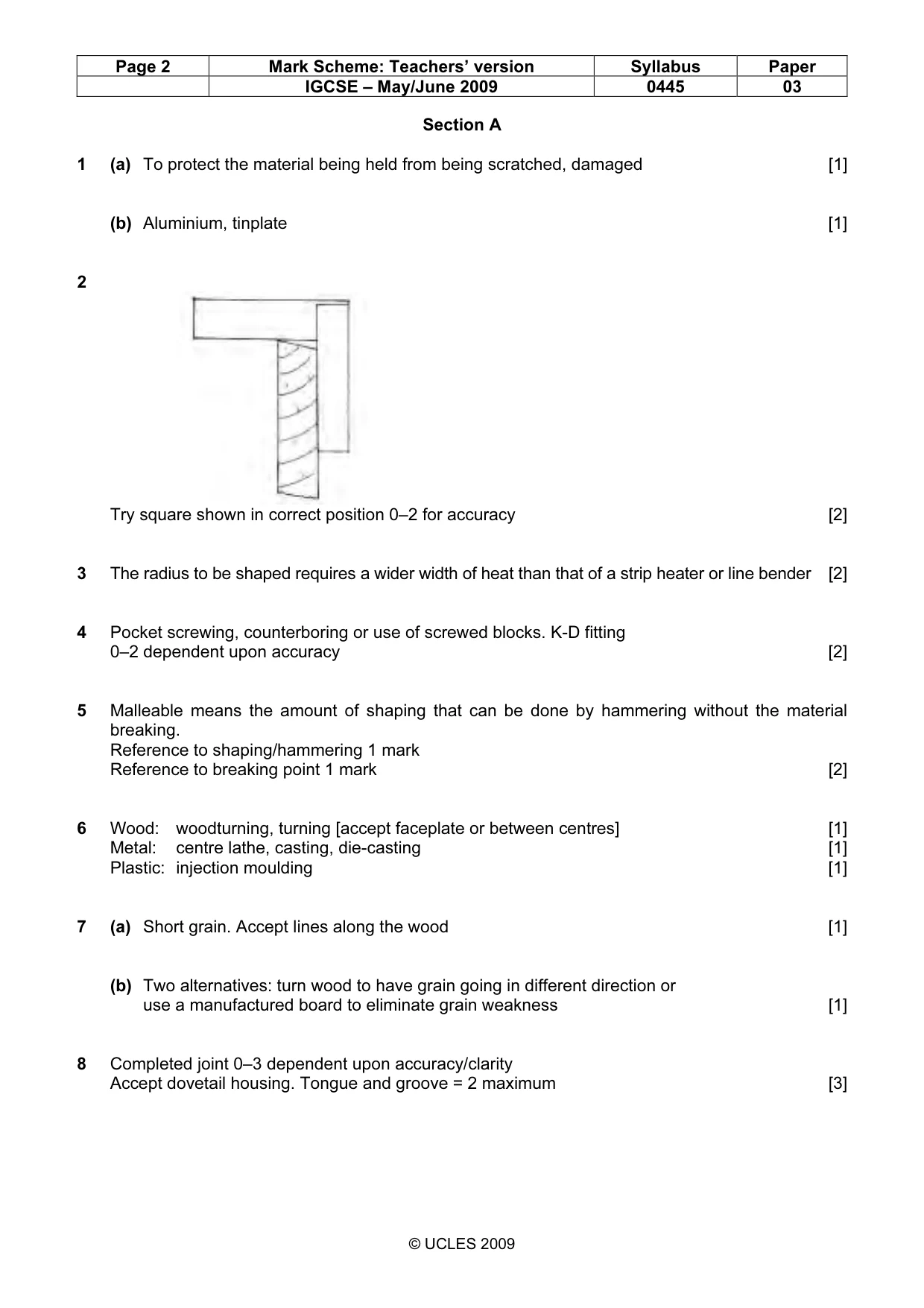
Page 2 Mark Scheme: Teachers’ version Syllabus Paper IGCSE – May/June 2009 0445 03 © UCLES 2009 Section A 1 (a) To protect the material being held from being scratched, damaged [1] (b) Aluminium, tinplate [1] 2 Try square shown in correct position 0–2 for accuracy [2] 3 The radius to be shaped requires a wider width of heat than that of a strip heater or line bender [2] 4 Pocket screwing, counterboring or use of screwed blocks. K-D fitting 0–2 dependent upon accuracy [2] 5 Malleable means the amount of shaping that can be done by hammering without the material breaking. Reference to shaping/hammering 1 mark Reference to breaking point 1 mark [2] 6 Wood: woodturning, turning [accept faceplate or between centres] [1] Metal: centre lathe, casting, die-casting [1] Plastic: injection moulding [1] 7 (a) Short grain. Accept lines along the wood [1] (b) Two alternatives: turn wood to have grain going in different direction or use a manufactured board to eliminate grain weakness [1] 8 Completed joint 0–3 dependent upon accuracy/clarity Accept dovetail housing. Tongue and groove = 2 maximum [3]
Mark scheme, page 3
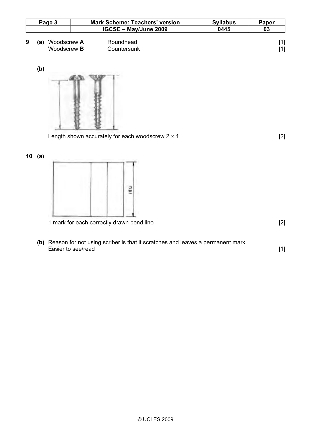
Page 3 Mark Scheme: Teachers’ version Syllabus Paper IGCSE – May/June 2009 0445 03 © UCLES 2009 9 (a) Woodscrew A Roundhead [1] Woodscrew B Countersunk [1] (b) Length shown accurately for each woodscrew 2 × 1 [2] 10 (a) 1 mark for each correctly drawn bend line [2] (b) Reason for not using scriber is that it scratches and leaves a permanent mark Easier to see/read [1]
Mark scheme, page 4
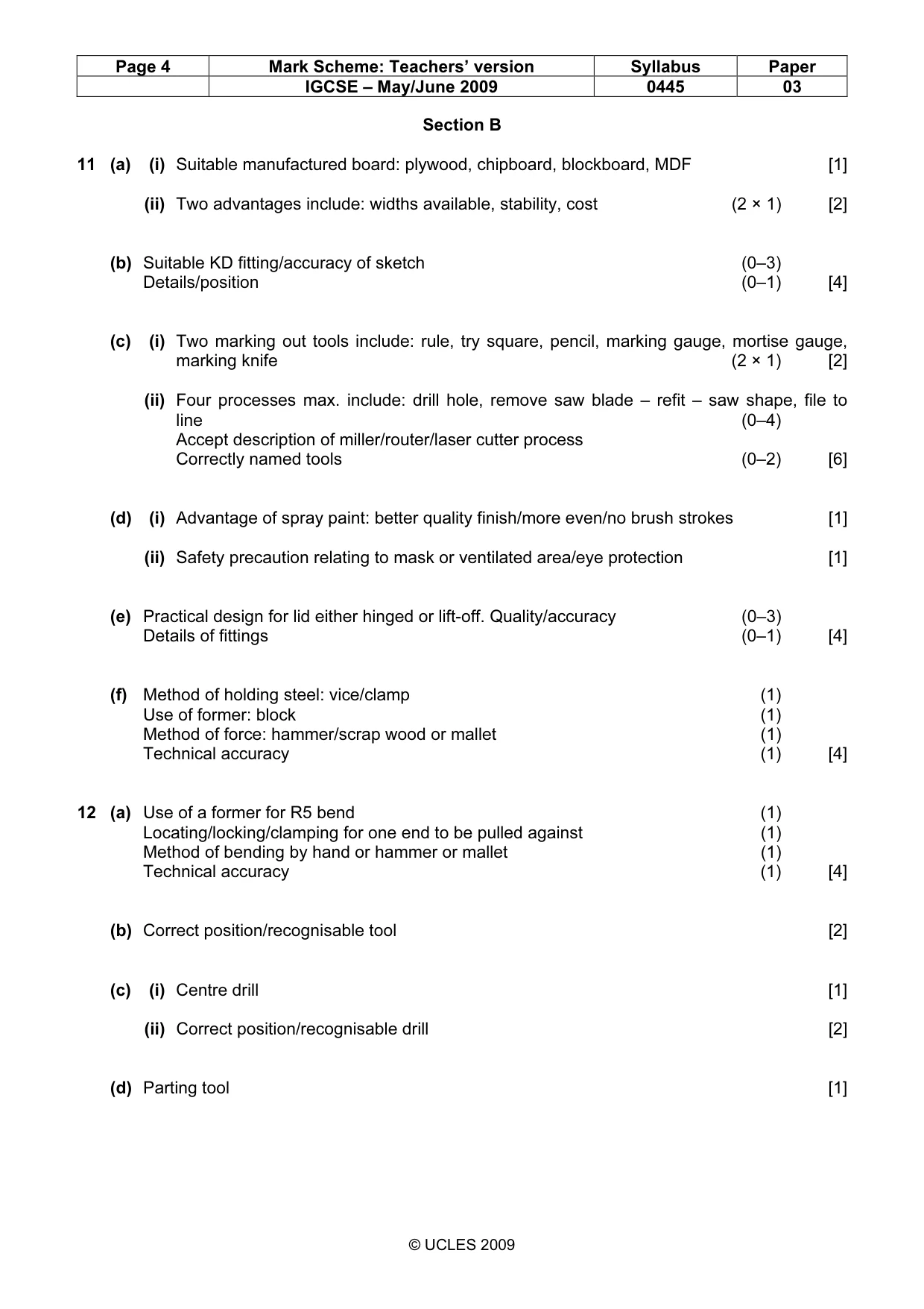
Page 4 Mark Scheme: Teachers’ version Syllabus Paper IGCSE – May/June 2009 0445 03 © UCLES 2009 Section B 11 (a) (i) Suitable manufactured board: plywood, chipboard, blockboard, MDF [1] (ii) Two advantages include: widths available, stability, cost (2 × 1) [2] (b) Suitable KD fitting/accuracy of sketch (0–3) Details/position (0–1) [4] (c) (i) Two marking out tools include: rule, try square, pencil, marking gauge, mortise gauge, marking knife (2 × 1) [2] (ii) Four processes max. include: drill hole, remove saw blade – refit – saw shape, file to line (0–4) Accept description of miller/router/laser cutter process Correctly named tools (0–2) [6] (d) (i) Advantage of spray paint: better quality finish/more even/no brush strokes [1] (ii) Safety precaution relating to mask or ventilated area/eye protection [1] (e) Practical design for lid either hinged or lift-off. Quality/accuracy (0–3) Details of fittings (0–1) [4] (f) Method of holding steel: vice/clamp (1) Use of former: block (1) Method of force: hammer/scrap wood or mallet (1) Technical accuracy (1) [4] 12 (a) Use of a former for R5 bend (1) Locating/locking/clamping for one end to be pulled against (1) Method of bending by hand or hammer or mallet (1) Technical accuracy (1) [4] (b) Correct position/recognisable tool [2] (c) (i) Centre drill [1] (ii) Correct position/recognisable drill [2] (d) Parting tool [1]
Mark scheme, page 5
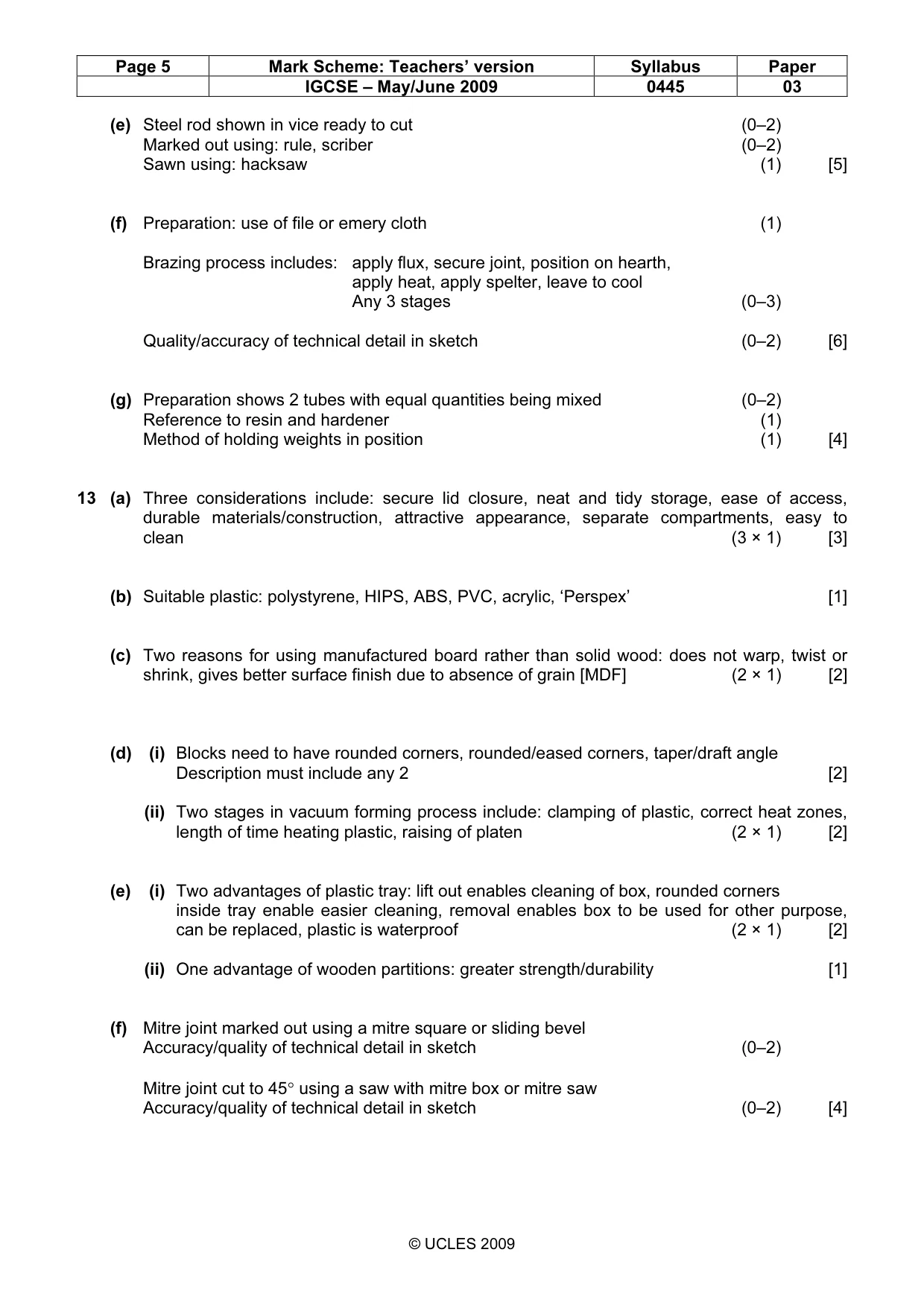
Page 5 Mark Scheme: Teachers’ version Syllabus Paper IGCSE – May/June 2009 0445 03 © UCLES 2009 (e) Steel rod shown in vice ready to cut (0–2) Marked out using: rule, scriber (0–2) Sawn using: hacksaw (1) [5] (f) Preparation: use of file or emery cloth (1) Brazing process includes: apply flux, secure joint, position on hearth, apply heat, apply spelter, leave to cool Any 3 stages (0–3) Quality/accuracy of technical detail in sketch (0–2) [6] (g) Preparation shows 2 tubes with equal quantities being mixed (0–2) Reference to resin and hardener (1) Method of holding weights in position (1) [4] 13 (a) Three considerations include: secure lid closure, neat and tidy storage, ease of access, durable materials/construction, attractive appearance, separate compartments, easy to clean (3 × 1) [3] (b) Suitable plastic: polystyrene, HIPS, ABS, PVC, acrylic, ‘Perspex’ [1] (c) Two reasons for using manufactured board rather than solid wood: does not warp, twist or shrink, gives better surface finish due to absence of grain [MDF] (2 × 1) [2] (d) (i) Blocks need to have rounded corners, rounded/eased corners, taper/draft angle Description must include any 2 [2] (ii) Two stages in vacuum forming process include: clamping of plastic, correct heat zones, length of time heating plastic, raising of platen (2 × 1) [2] (e) (i) Two advantages of plastic tray: lift out enables cleaning of box, rounded corners inside tray enable easier cleaning, removal enables box to be used for other purpose, can be replaced, plastic is waterproof (2 × 1) [2] (ii) One advantage of wooden partitions: greater strength/durability [1] (f) Mitre joint marked out using a mitre square or sliding bevel Accuracy/quality of technical detail in sketch (0–2) Mitre joint cut to 45° using a saw with mitre box or mitre saw Accuracy/quality of technical detail in sketch (0–2) [4]
Mark scheme, page 6
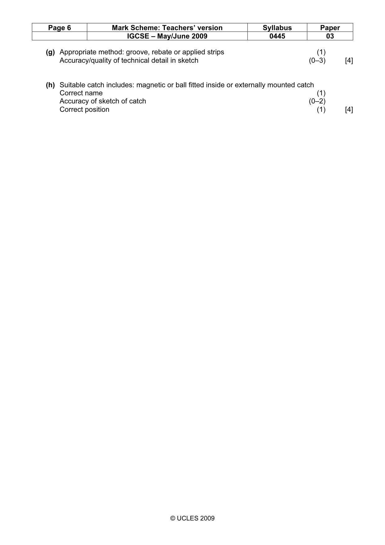
Page 6 Mark Scheme: Teachers’ version Syllabus Paper IGCSE – May/June 2009 0445 03 © UCLES 2009 (g) Appropriate method: groove, rebate or applied strips (1) Accuracy/quality of technical detail in sketch (0–3) [4] (h) Suitable catch includes: magnetic or ball fitted inside or externally mounted catch Correct name (1) Accuracy of sketch of catch (0–2) Correct position (1) [4]
What you needed in this session
Cambridge’s own grade thresholds for 2009 May/June, Paper 3 · Variant 1. A higher threshold means an easier paper — the bar moves with how the cohort did.