Cambridge IGCSE Design and Technology 0445 — 2007 Oct/Nov Paper 3 · Variant 1
0445/31/O/N/07 · 50 marks · ≈56 min
The question paper and its mark scheme, free to read here and free to download. This is Cambridge’s own paper, exactly as it was sat.
Question paper16 pages
Mark scheme5 pages
Answers below. Sit the paper first if you are practising.
Paper as text
Question paper, page 1
This document consists of 15 printed pages and 1 blank page. IB07 11_0445_03/2RP © UCLES 2007 [Turn over *5561061723* For Examiner's Use 1 2 Total UNIVERSITY OF CAMBRIDGE INTERNATIONAL EXAMINATIONS International General Certificate of Secondary Education DESIGN AND TECHNOLOGY 0445/03 Paper 3 Resistant Materials October/November 2007 1 hour Candidates answer on the Question Paper. No Additional Materials are required. To be taken together with Paper 1 in one session of 2 hours 15 minutes. READ THESE INSTRUCTIONS FIRST Write your Centre number, candidate number and name on all the work you hand in. Write in dark blue or black pen. You may use a soft pencil for any diagrams graphs or rough working. Do not use staples, paper clips, highlighters, glue or correction fluid. DO NOT WRITE IN ANY BARCODES. Section A Answer all questions. Section B Answer one question. You may use a calculator. At the end of the examination, fasten all your work securely together. The number of marks is given in brackets [ ] at the end of each question or part question. www.XtremePapers.com
Question paper, page 2
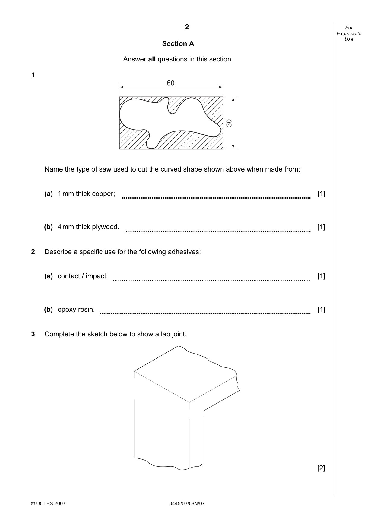
2 © UCLES 2007 0445/03/O/N/07 For Examiner's Use Section A Answer all questions in this section. 1 60 30 Name the type of saw used to cut the curved shape shown above when made from: (a) 1 mm thick copper; [1] (b) 4 mm thick plywood. [1] 2 Describe a specific use for the following adhesives: (a) contact / impact; [1] (b) epoxy resin. [1] 3 Complete the sketch below to show a lap joint. [2]
Question paper, page 3
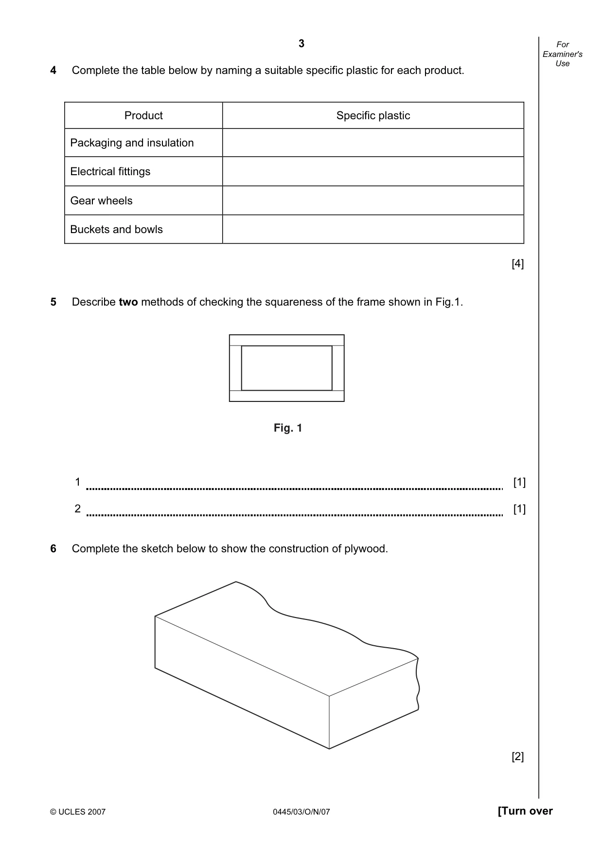
3 © UCLES 2007 0445/03/O/N/07 [Turn over For Examiner's Use 4 Complete the table below by naming a suitable specific plastic for each product. Product Specific plastic Packaging and insulation Electrical fittings Gear wheels Buckets and bowls [4] 5 Describe two methods of checking the squareness of the frame shown in Fig.1. Fig. 1 1 [1] 2 [1] 6 Complete the sketch below to show the construction of plywood. [2]
Question paper, page 4
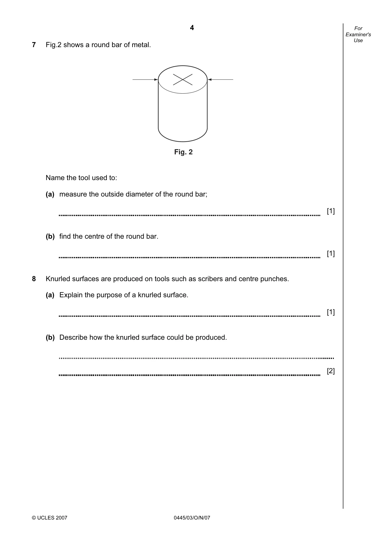
4 © UCLES 2007 0445/03/O/N/07 For Examiner's Use 7 Fig.2 shows a round bar of metal. Fig. 2 Name the tool used to: (a) measure the outside diameter of the round bar; [1] (b) find the centre of the round bar. [1] 8 Knurled surfaces are produced on tools such as scribers and centre punches. (a) Explain the purpose of a knurled surface. [1] (b) Describe how the knurled surface could be produced. [2]
Question paper, page 5
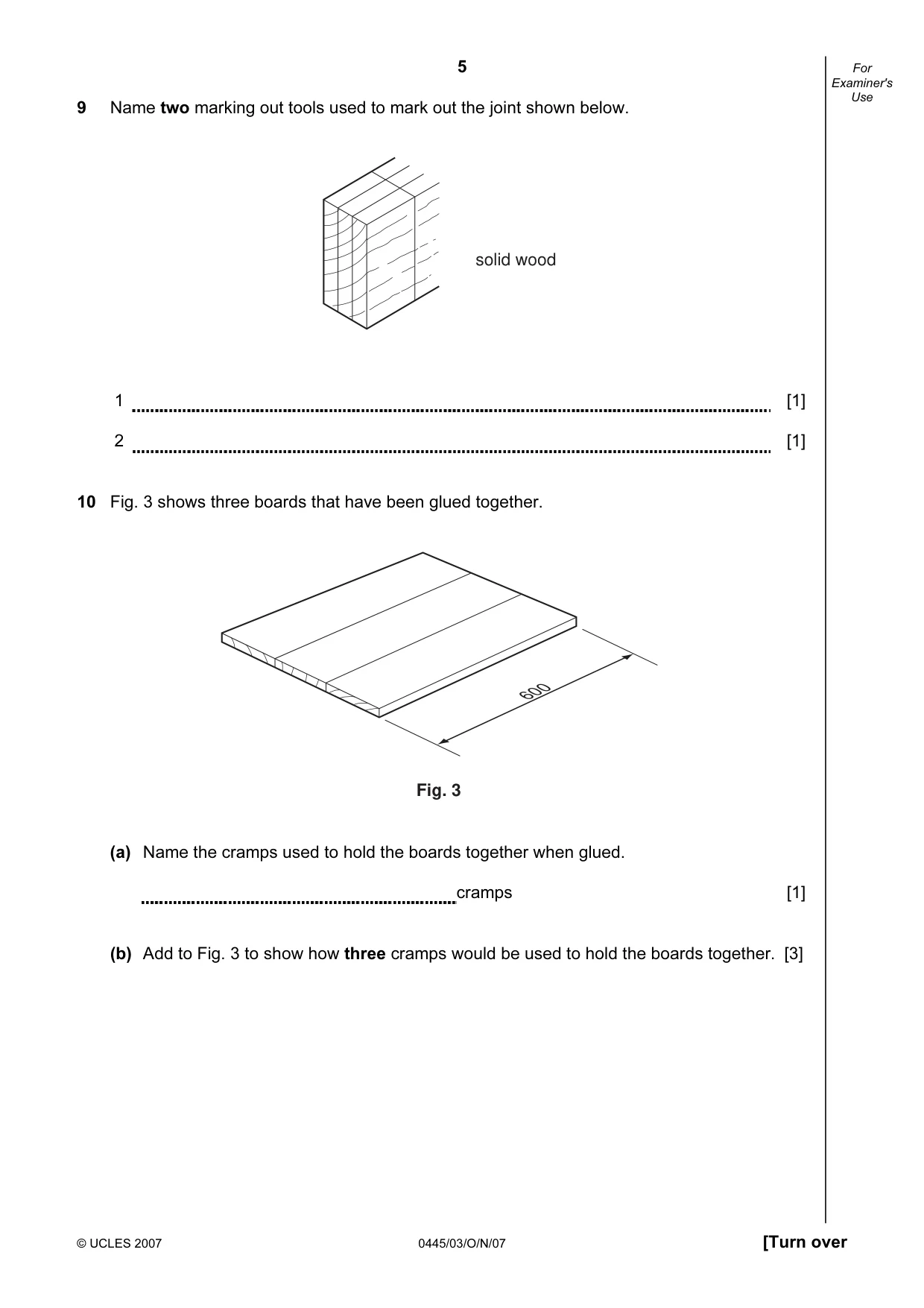
5 © UCLES 2007 0445/03/O/N/07 [Turn over For Examiner's Use 9 Name two marking out tools used to mark out the joint shown below. solid wood 1 [1] 2 [1] 10 Fig. 3 shows three boards that have been glued together. 600 Fig. 3 (a) Name the cramps used to hold the boards together when glued. cramps [1] (b) Add to Fig. 3 to show how three cramps would be used to hold the boards together. [3]
Question paper, page 6
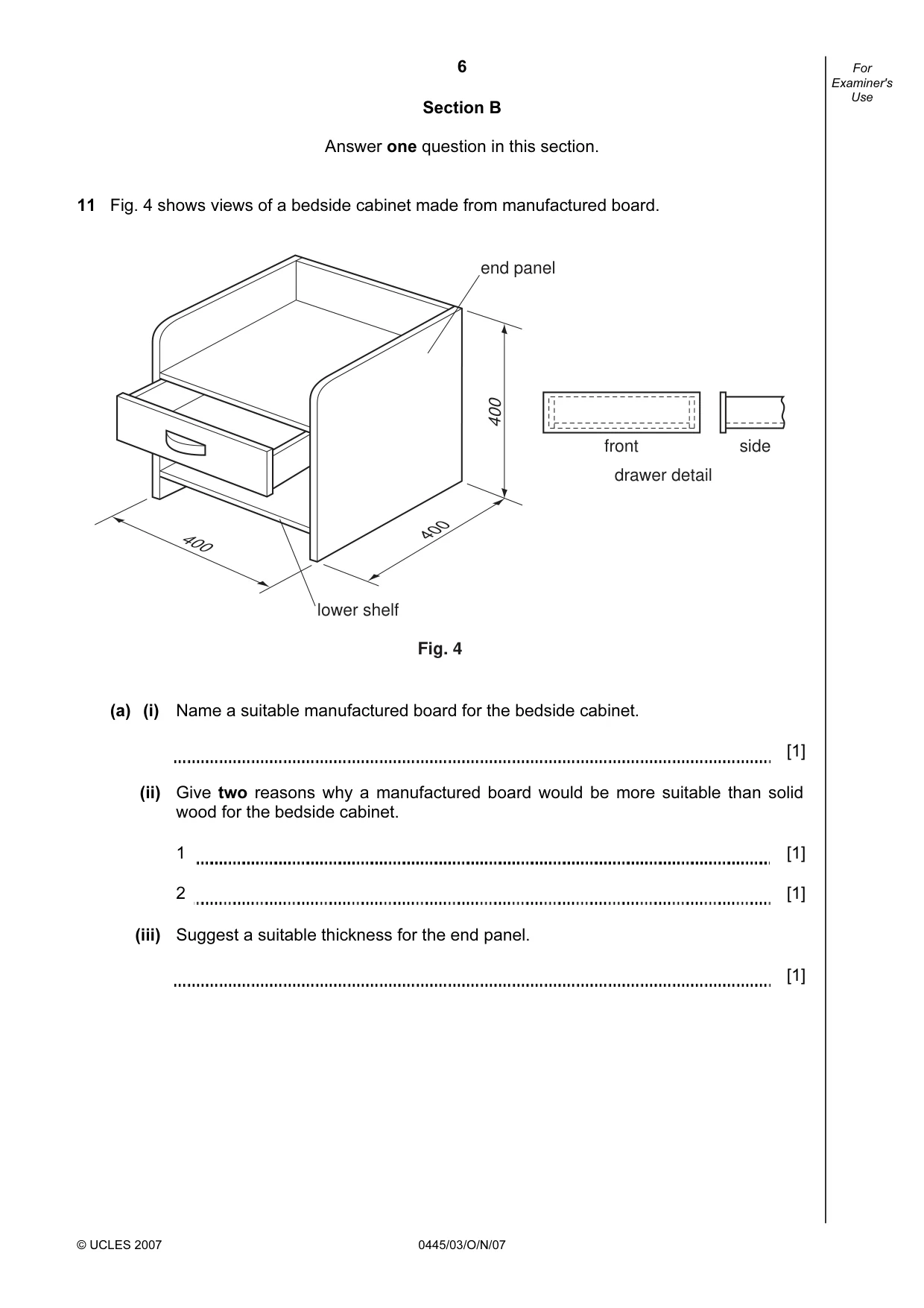
6 © UCLES 2007 0445/03/O/N/07 For Examiner's Use Section B Answer one question in this section. 11 Fig. 4 shows views of a bedside cabinet made from manufactured board. 400 lower shelf end panel Fig. 4 400 400 front side drawer detail (a) (i) Name a suitable manufactured board for the bedside cabinet. [1] (ii) Give two reasons why a manufactured board would be more suitable than solid wood for the bedside cabinet. 1 [1] 2 [1] (iii) Suggest a suitable thickness for the end panel. [1]
Question paper, page 7
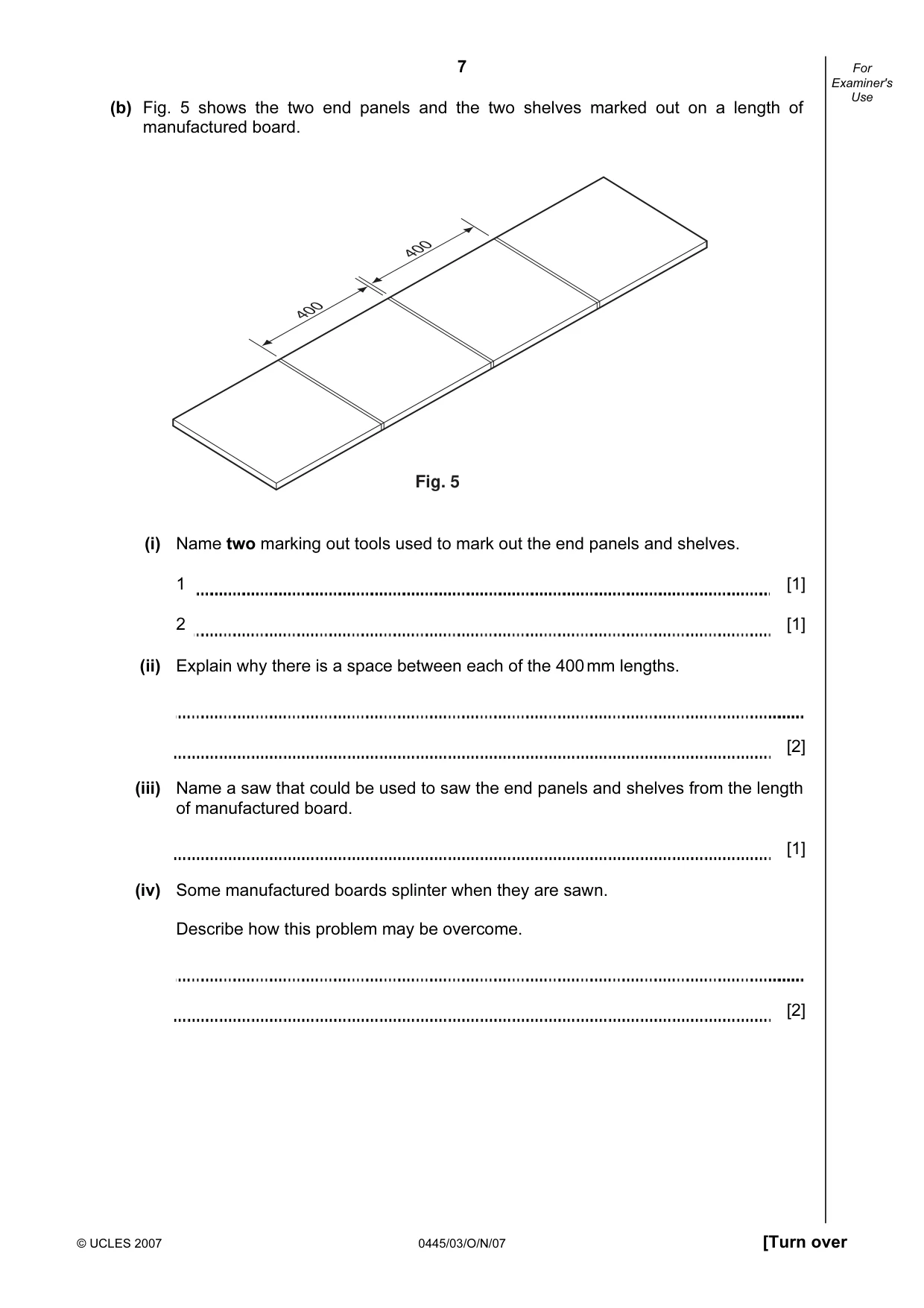
7 © UCLES 2007 0445/03/O/N/07 [Turn over For Examiner's Use (b) Fig. 5 shows the two end panels and the two shelves marked out on a length of manufactured board. 400 400 Fig. 5 (i) Name two marking out tools used to mark out the end panels and shelves. 1 [1] 2 [1] (ii) Explain why there is a space between each of the 400 mm lengths. [2] (iii) Name a saw that could be used to saw the end panels and shelves from the length of manufactured board. [1] (iv) Some manufactured boards splinter when they are sawn. Describe how this problem may be overcome. [2]
Question paper, page 8
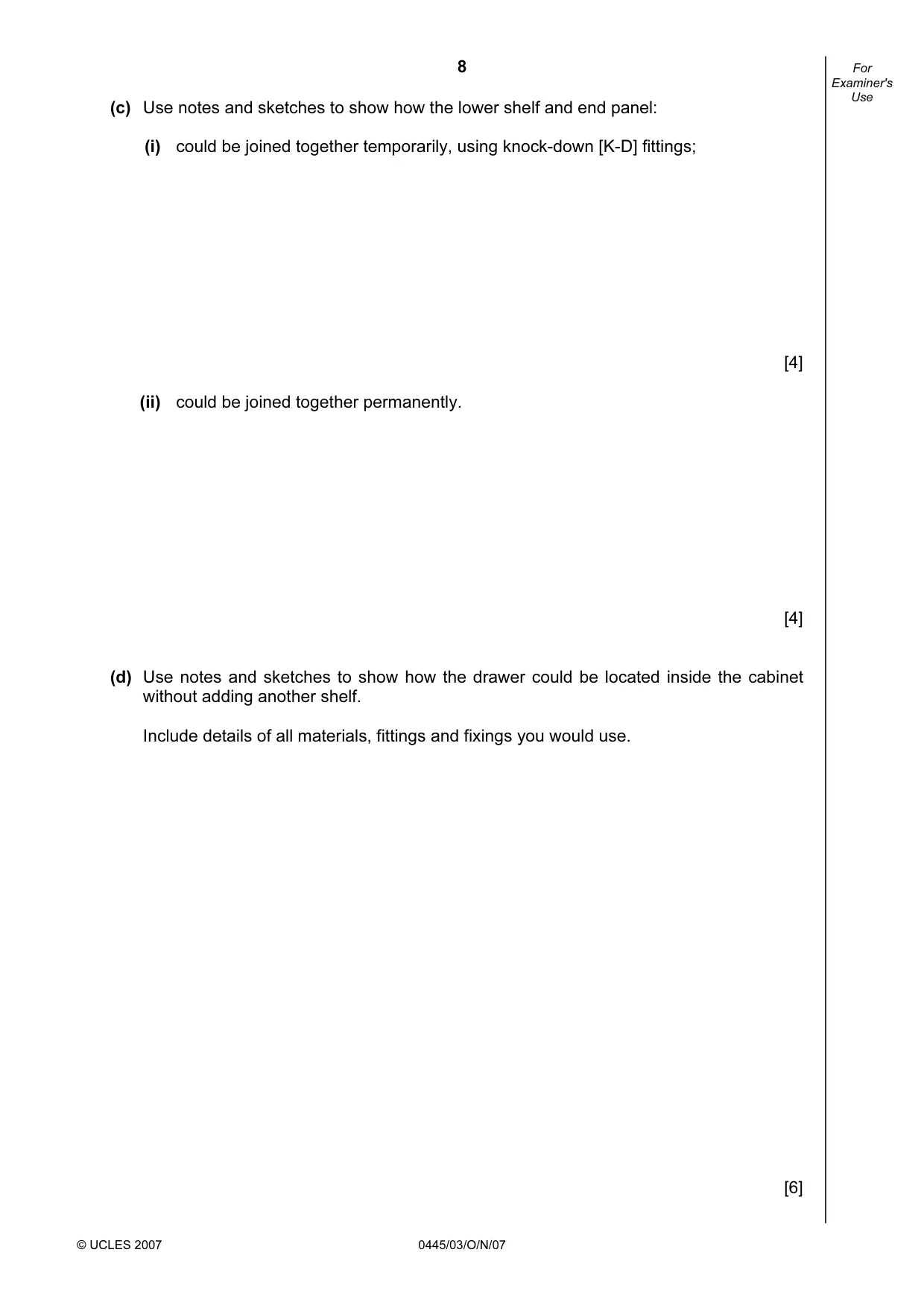
8 © UCLES 2007 0445/03/O/N/07 For Examiner's Use (c) Use notes and sketches to show how the lower shelf and end panel: (i) could be joined together temporarily, using knock-down [K-D] fittings; [4] (ii) could be joined together permanently. [4] (d) Use notes and sketches to show how the drawer could be located inside the cabinet without adding another shelf. Include details of all materials, fittings and fixings you would use. [6]
Question paper, page 9
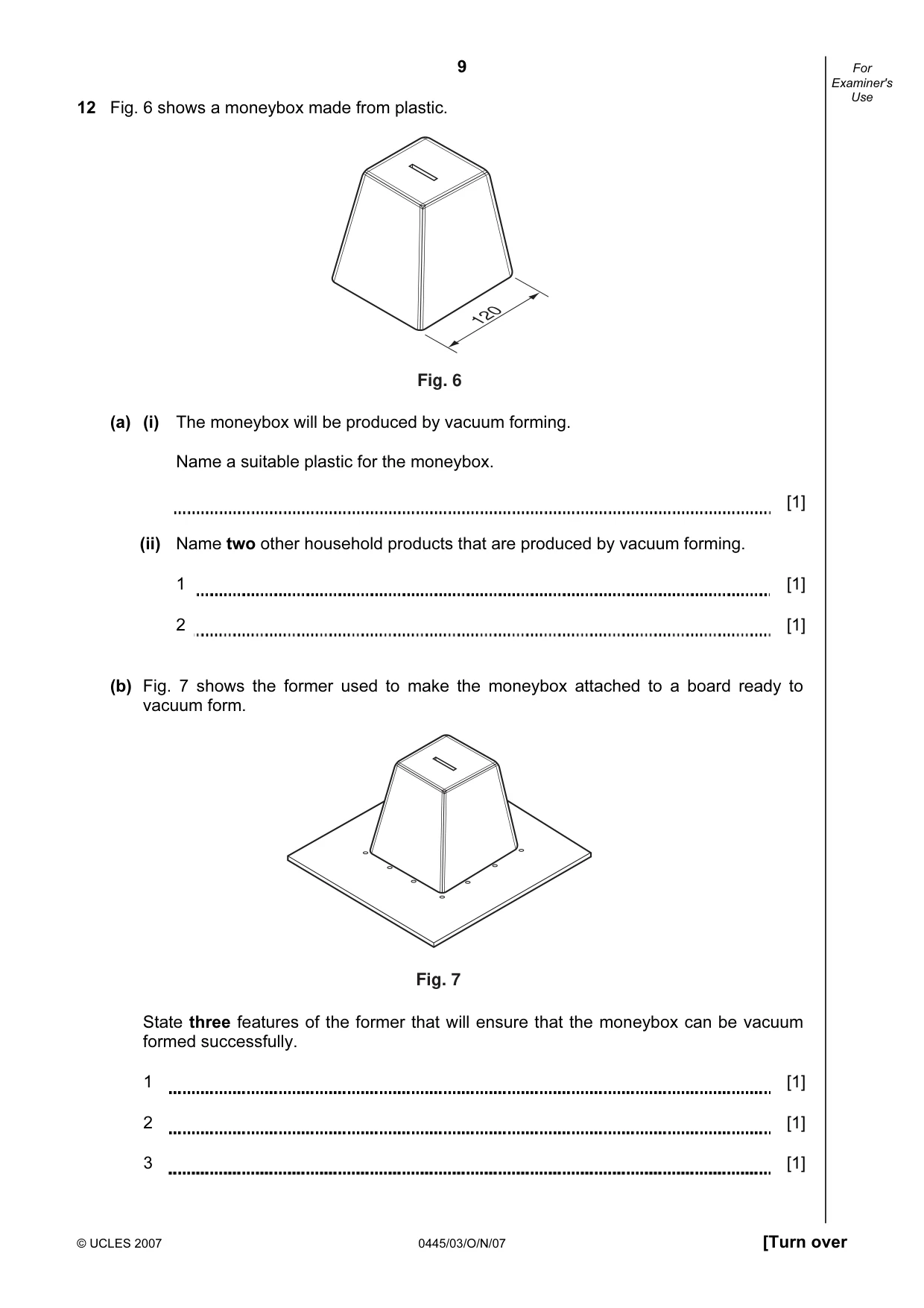
9 © UCLES 2007 0445/03/O/N/07 [Turn over For Examiner's Use 12 Fig. 6 shows a moneybox made from plastic. Fig. 6 120 (a) (i) The moneybox will be produced by vacuum forming. Name a suitable plastic for the moneybox. [1] (ii) Name two other household products that are produced by vacuum forming. 1 [1] 2 [1] (b) Fig. 7 shows the former used to make the moneybox attached to a board ready to vacuum form. Fig. 7 State three features of the former that will ensure that the moneybox can be vacuum formed successfully. 1 [1] 2 [1] 3 [1]
Question paper, page 10
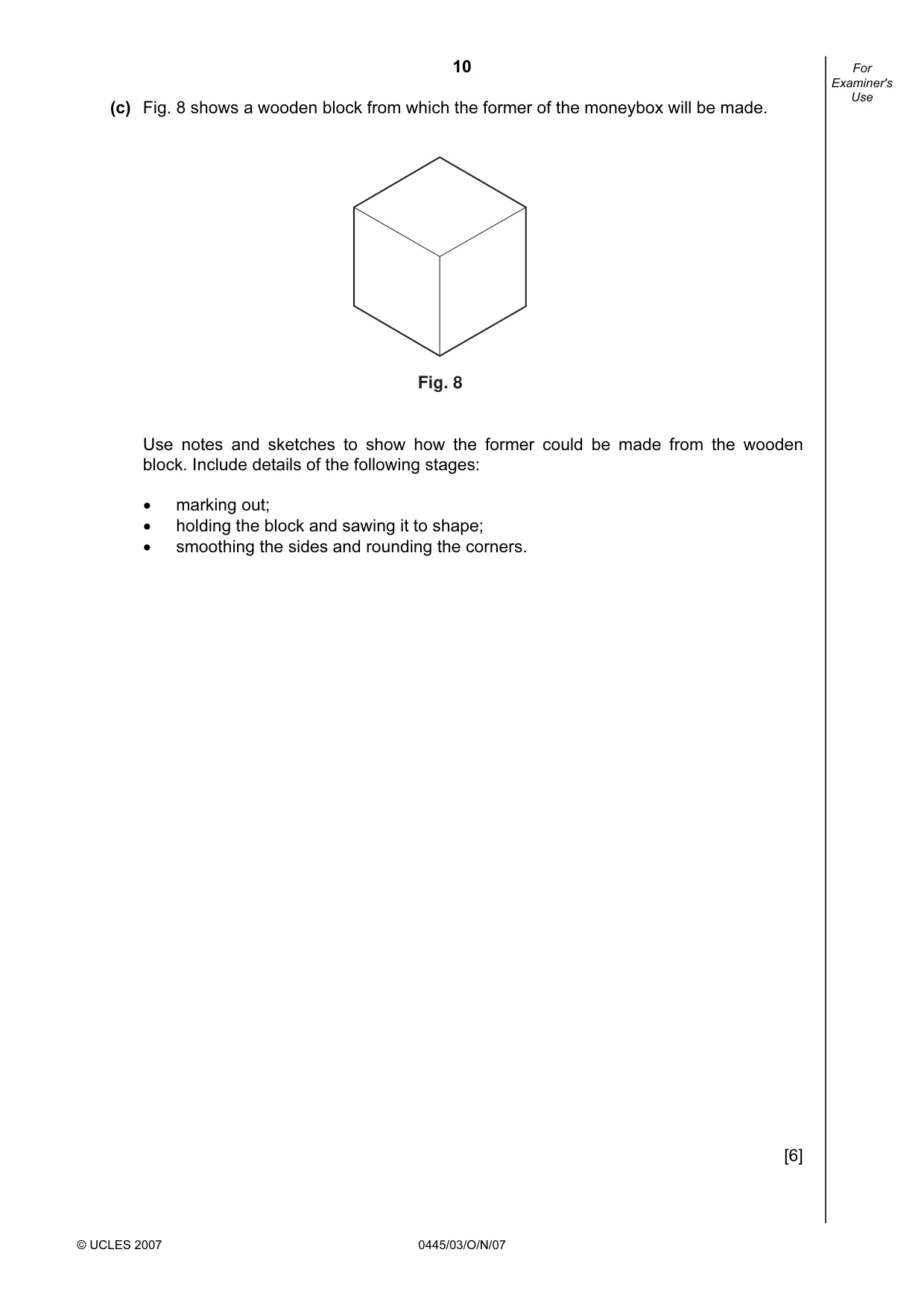
10 © UCLES 2007 0445/03/O/N/07 For Examiner's Use (c) Fig. 8 shows a wooden block from which the former of the moneybox will be made. Fig. 8 Use notes and sketches to show how the former could be made from the wooden block. Include details of the following stages: • marking out; • holding the block and sawing it to shape; • smoothing the sides and rounding the corners. [6]
Question paper, page 11
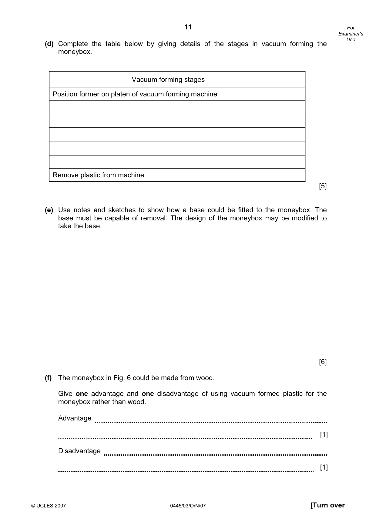
11 © UCLES 2007 0445/03/O/N/07 [Turn over For Examiner's Use (d) Complete the table below by giving details of the stages in vacuum forming the moneybox. Vacuum forming stages Position former on platen of vacuum forming machine Remove plastic from machine [5] (e) Use notes and sketches to show how a base could be fitted to the moneybox. The base must be capable of removal. The design of the moneybox may be modified to take the base. [6] (f) The moneybox in Fig. 6 could be made from wood. Give one advantage and one disadvantage of using vacuum formed plastic for the moneybox rather than wood. Advantage [1] Disadvantage [1]
Question paper, page 12
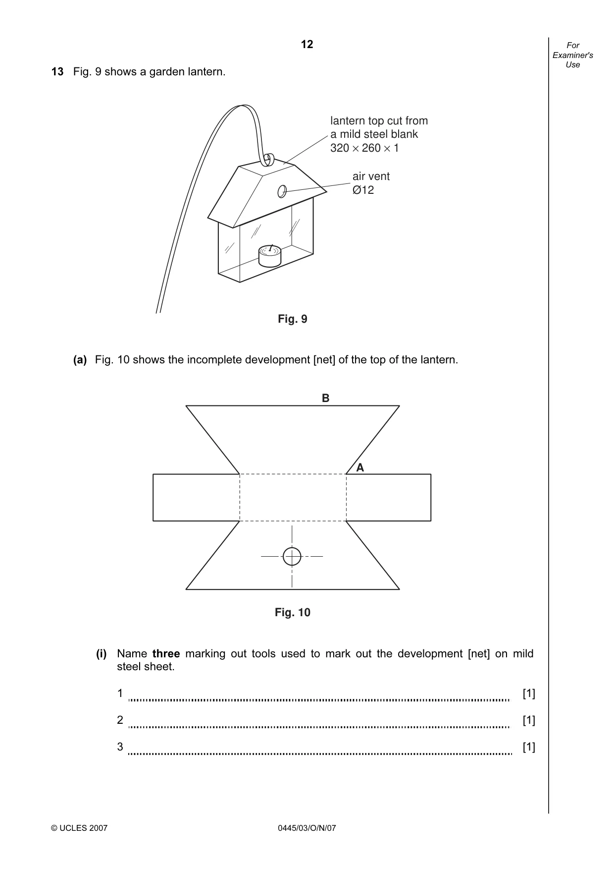
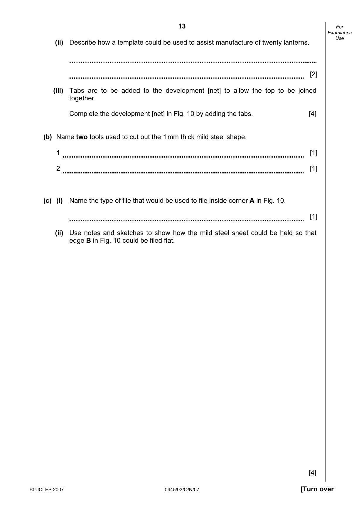
12 © UCLES 2007 0445/03/O/N/07 For Examiner's Use 13 Fig. 9 shows a garden lantern. air vent Ø12 lantern top cut from a mild steel blank 320 × 260 × 1 Fig. 9 (a) Fig. 10 shows the incomplete development [net] of the top of the lantern. B A Fig. 10 (i) Name three marking out tools used to mark out the development [net] on mild steel sheet. 1 [1] 2 [1] 3 [1]
Question paper, page 13
13 © UCLES 2007 0445/03/O/N/07 [Turn over For Examiner's Use (ii) Describe how a template could be used to assist manufacture of twenty lanterns. [2] (iii) Tabs are to be added to the development [net] to allow the top to be joined together. Complete the development [net] in Fig. 10 by adding the tabs. [4] (b) Name two tools used to cut out the 1 mm thick mild steel shape. 1 [1] 2 [1] (c) (i) Name the type of file that would be used to file inside corner A in Fig. 10. [1] (ii) Use notes and sketches to show how the mild steel sheet could be held so that edge B in Fig. 10 could be filed flat. [4]
Question paper, page 14
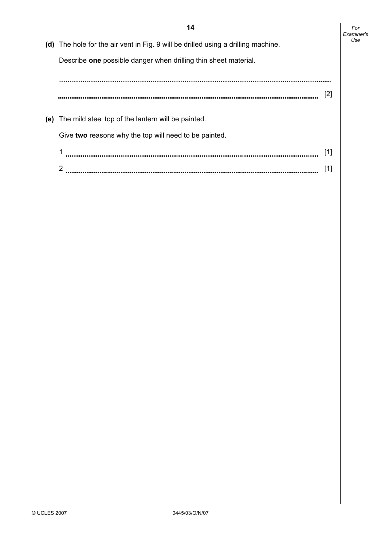
14 © UCLES 2007 0445/03/O/N/07 For Examiner's Use (d) The hole for the air vent in Fig. 9 will be drilled using a drilling machine. Describe one possible danger when drilling thin sheet material. [2] (e) The mild steel top of the lantern will be painted. Give two reasons why the top will need to be painted. 1 [1] 2 [1]
Question paper, page 15
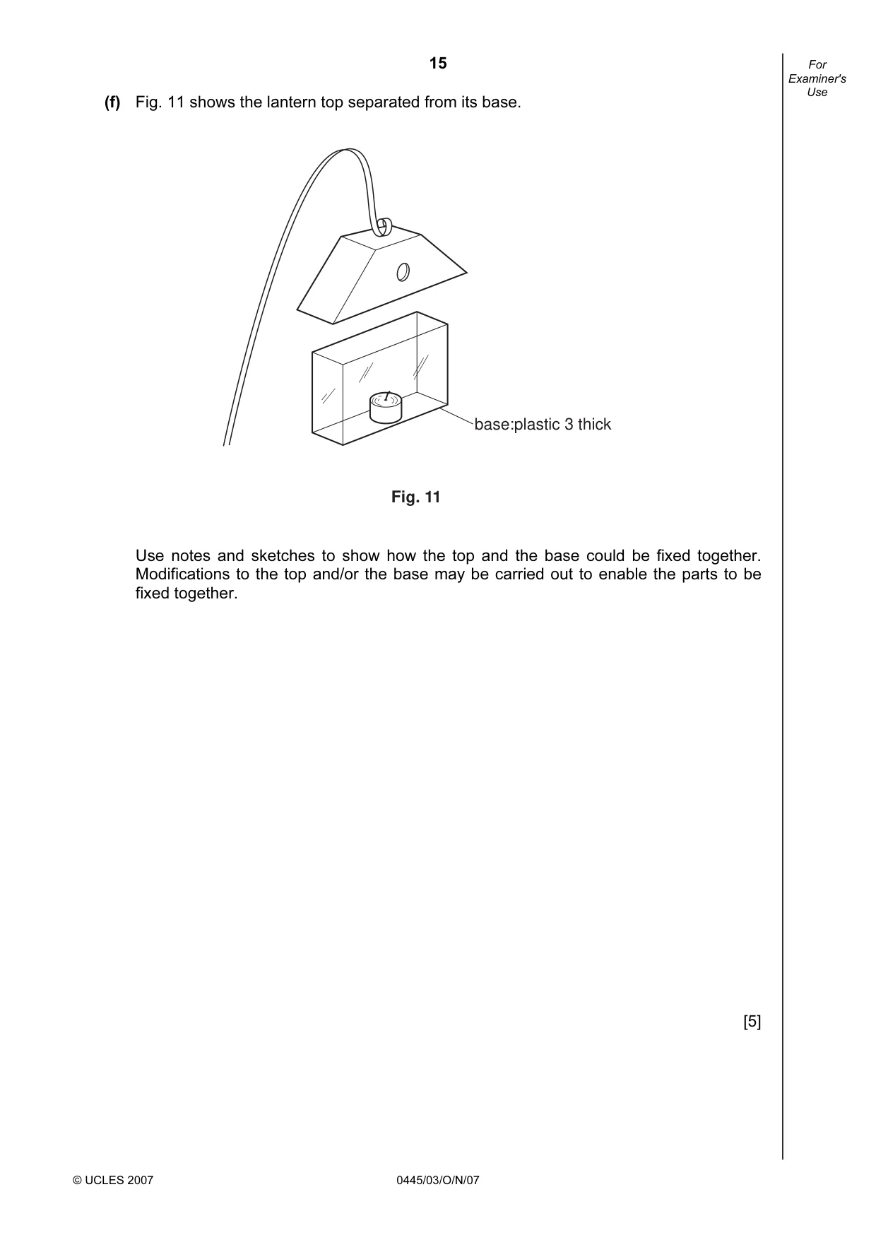
15 © UCLES 2007 0445/03/O/N/07 For Examiner's Use (f) Fig. 11 shows the lantern top separated from its base. Fig. 11 base:plastic 3 thick Use notes and sketches to show how the top and the base could be fixed together. Modifications to the top and/or the base may be carried out to enable the parts to be fixed together. [5]
Question paper, page 16
16 Copyright Acknowledgements: Permission to reproduce items where third-party owned material protected by copyright is included has been sought and cleared where possible. Every reasonable effort has been made by the publisher (UCLES) to trace copyright holders, but if any items requiring clearance have unwittingly been included, the publisher will be pleased to make amends at the earliest possible opportunity. University of Cambridge International Examinations is part of the Cambridge Assessment Group. Cambridge Assessment is the brand name of University of Cambridge Local Examinations Syndicate (UCLES), which is itself a department of the University of Cambridge. 0445/03/O/N/07 BLANK PAGE
Mark scheme, page 1
UNIVERSITY OF CAMBRIDGE INTERNATIONAL EXAMINATIONS International General Certificate of Secondary Education MARK SCHEME for the October/November 2007 question paper 0445 DESIGN AND TECHNOLOGY 0445/03 Paper 3 (Realisation), maximum raw mark 50 This mark scheme is published as an aid to teachers and candidates, to indicate the requirements of the examination. It shows the basis on which Examiners were instructed to award marks. It does not indicate the details of the discussions that took place at an Examiners’ meeting before marking began. All Examiners are instructed that alternative correct answers and unexpected approaches in candidates’ scripts must be given marks that fairly reflect the relevant knowledge and skills demonstrated. Mark schemes must be read in conjunction with the question papers and the report on the examination. • CIE will not enter into discussions or correspondence in connection with these mark schemes. CIE is publishing the mark schemes for the October/November 2007 question papers for most IGCSE, GCE Advanced Level and Advanced Subsidiary Level syllabuses and some Ordinary Level syllabuses. www.XtremePapers.com
Mark scheme, page 2
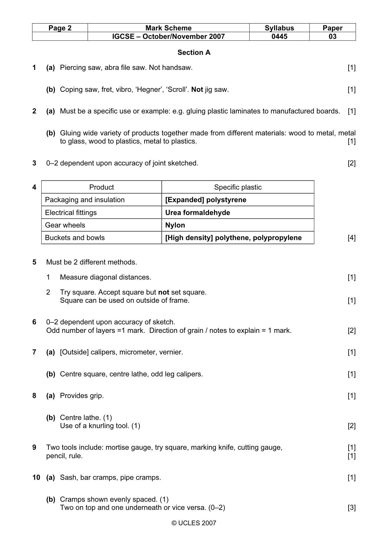
Page 2 Mark Scheme Syllabus Paper IGCSE – October/November 2007 0445 03 © UCLES 2007 Section A 1 (a) Piercing saw, abra file saw. Not handsaw. [1] (b) Coping saw, fret, vibro, ‘Hegner’, ‘Scroll’. Not jig saw. [1] 2 (a) Must be a specific use or example: e.g. gluing plastic laminates to manufactured boards. [1] (b) Gluing wide variety of products together made from different materials: wood to metal, metal to glass, wood to plastics, metal to plastics. [1] 3 0–2 dependent upon accuracy of joint sketched. [2] 4 Product Specific plastic Packaging and insulation [Expanded] polystyrene Electrical fittings Urea formaldehyde Gear wheels Nylon Buckets and bowls [High density] polythene, polypropylene [4] 5 Must be 2 different methods. 1 Measure diagonal distances. [1] 2 Try square. Accept square but not set square. Square can be used on outside of frame. [1] 6 0–2 dependent upon accuracy of sketch. Odd number of layers =1 mark. Direction of grain / notes to explain = 1 mark. [2] 7 (a) [Outside] calipers, micrometer, vernier. [1] (b) Centre square, centre lathe, odd leg calipers. [1] 8 (a) Provides grip. [1] (b) Centre lathe. (1) Use of a knurling tool. (1) [2] 9 Two tools include: mortise gauge, try square, marking knife, cutting gauge, [1] pencil, rule. [1] 10 (a) Sash, bar cramps, pipe cramps. [1] (b) Cramps shown evenly spaced. (1) Two on top and one underneath or vice versa. (0–2) [3]
Mark scheme, page 3
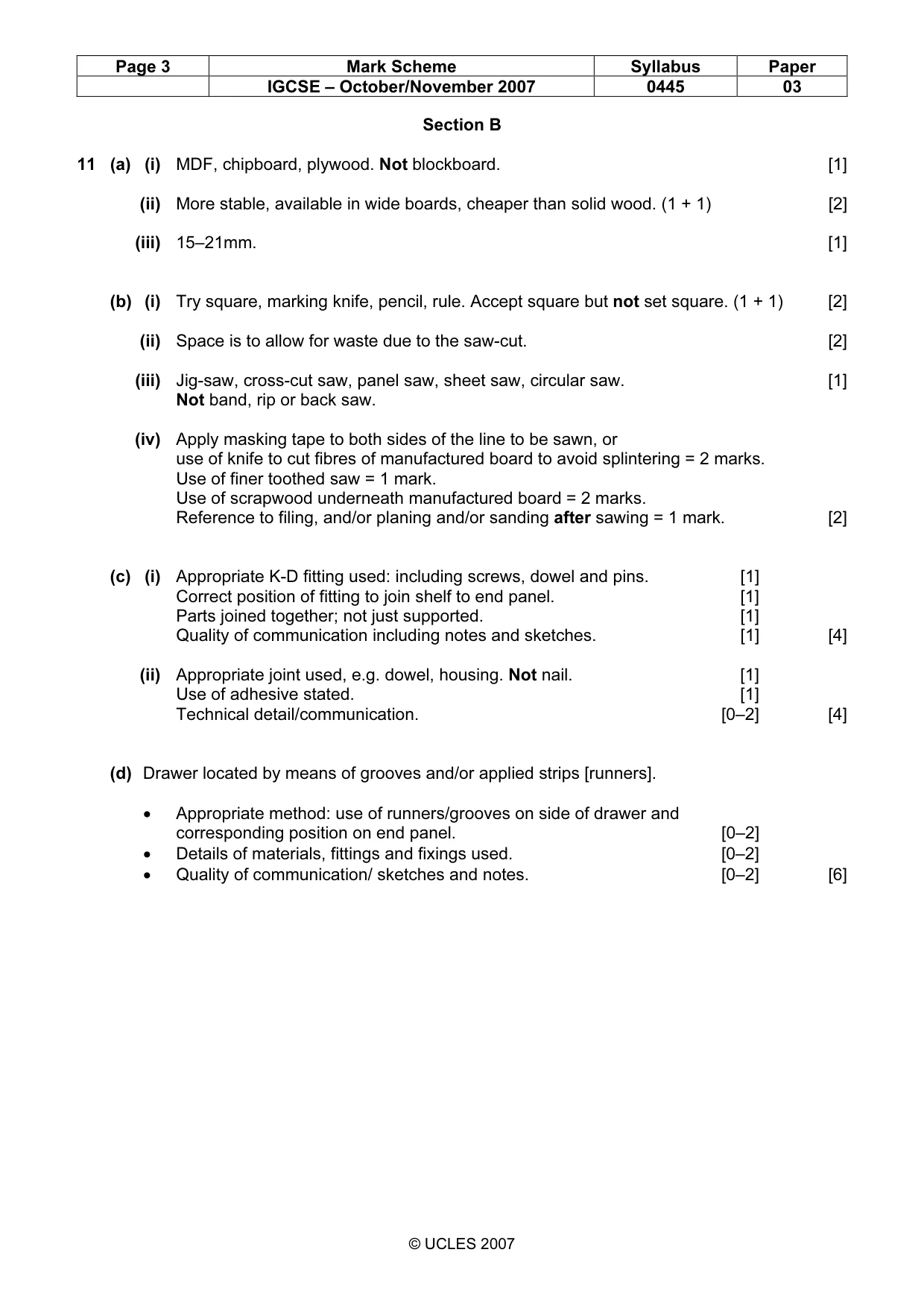
Page 3 Mark Scheme Syllabus Paper IGCSE – October/November 2007 0445 03 © UCLES 2007 Section B 11 (a) (i) MDF, chipboard, plywood. Not blockboard. [1] (ii) More stable, available in wide boards, cheaper than solid wood. (1 + 1) [2] (iii) 15–21mm. [1] (b) (i) Try square, marking knife, pencil, rule. Accept square but not set square. (1 + 1) [2] (ii) Space is to allow for waste due to the saw-cut. [2] (iii) Jig-saw, cross-cut saw, panel saw, sheet saw, circular saw. [1] Not band, rip or back saw. (iv) Apply masking tape to both sides of the line to be sawn, or use of knife to cut fibres of manufactured board to avoid splintering = 2 marks. Use of finer toothed saw = 1 mark. Use of scrapwood underneath manufactured board = 2 marks. Reference to filing, and/or planing and/or sanding after sawing = 1 mark. [2] (c) (i) Appropriate K-D fitting used: including screws, dowel and pins. [1] Correct position of fitting to join shelf to end panel. [1] Parts joined together; not just supported. [1] Quality of communication including notes and sketches. [1] [4] (ii) Appropriate joint used, e.g. dowel, housing. Not nail. [1] Use of adhesive stated. [1] Technical detail/communication. [0–2] [4] (d) Drawer located by means of grooves and/or applied strips [runners]. • Appropriate method: use of runners/grooves on side of drawer and corresponding position on end panel. [0–2] • Details of materials, fittings and fixings used. [0–2] • Quality of communication/ sketches and notes. [0–2] [6]
Mark scheme, page 4
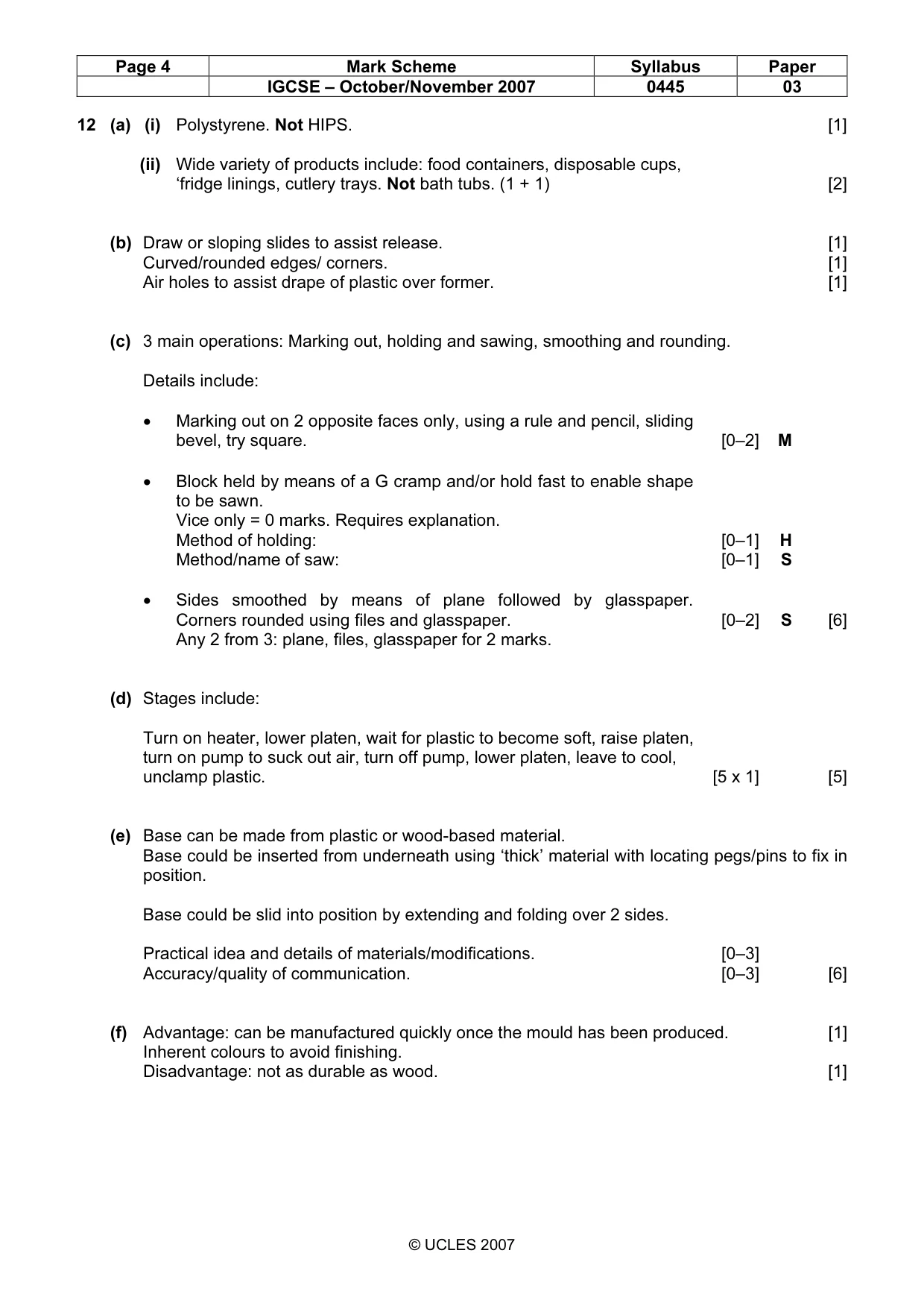
Page 4 Mark Scheme Syllabus Paper IGCSE – October/November 2007 0445 03 © UCLES 2007 12 (a) (i) Polystyrene. Not HIPS. [1] (ii) Wide variety of products include: food containers, disposable cups, ‘fridge linings, cutlery trays. Not bath tubs. (1 + 1) [2] (b) Draw or sloping slides to assist release. [1] Curved/rounded edges/ corners. [1] Air holes to assist drape of plastic over former. [1] (c) 3 main operations: Marking out, holding and sawing, smoothing and rounding. Details include: • Marking out on 2 opposite faces only, using a rule and pencil, sliding bevel, try square. [0–2] M • Block held by means of a G cramp and/or hold fast to enable shape to be sawn. Vice only = 0 marks. Requires explanation. Method of holding: [0–1] H Method/name of saw: [0–1] S • Sides smoothed by means of plane followed by glasspaper. Corners rounded using files and glasspaper. [0–2] S [6] Any 2 from 3: plane, files, glasspaper for 2 marks. (d) Stages include: Turn on heater, lower platen, wait for plastic to become soft, raise platen, turn on pump to suck out air, turn off pump, lower platen, leave to cool, unclamp plastic. [5 x 1] [5] (e) Base can be made from plastic or wood-based material. Base could be inserted from underneath using ‘thick’ material with locating pegs/pins to fix in position. Base could be slid into position by extending and folding over 2 sides. Practical idea and details of materials/modifications. [0–3] Accuracy/quality of communication. [0–3] [6] (f) Advantage: can be manufactured quickly once the mould has been produced. [1] Inherent colours to avoid finishing. Disadvantage: not as durable as wood. [1]
Mark scheme, page 5
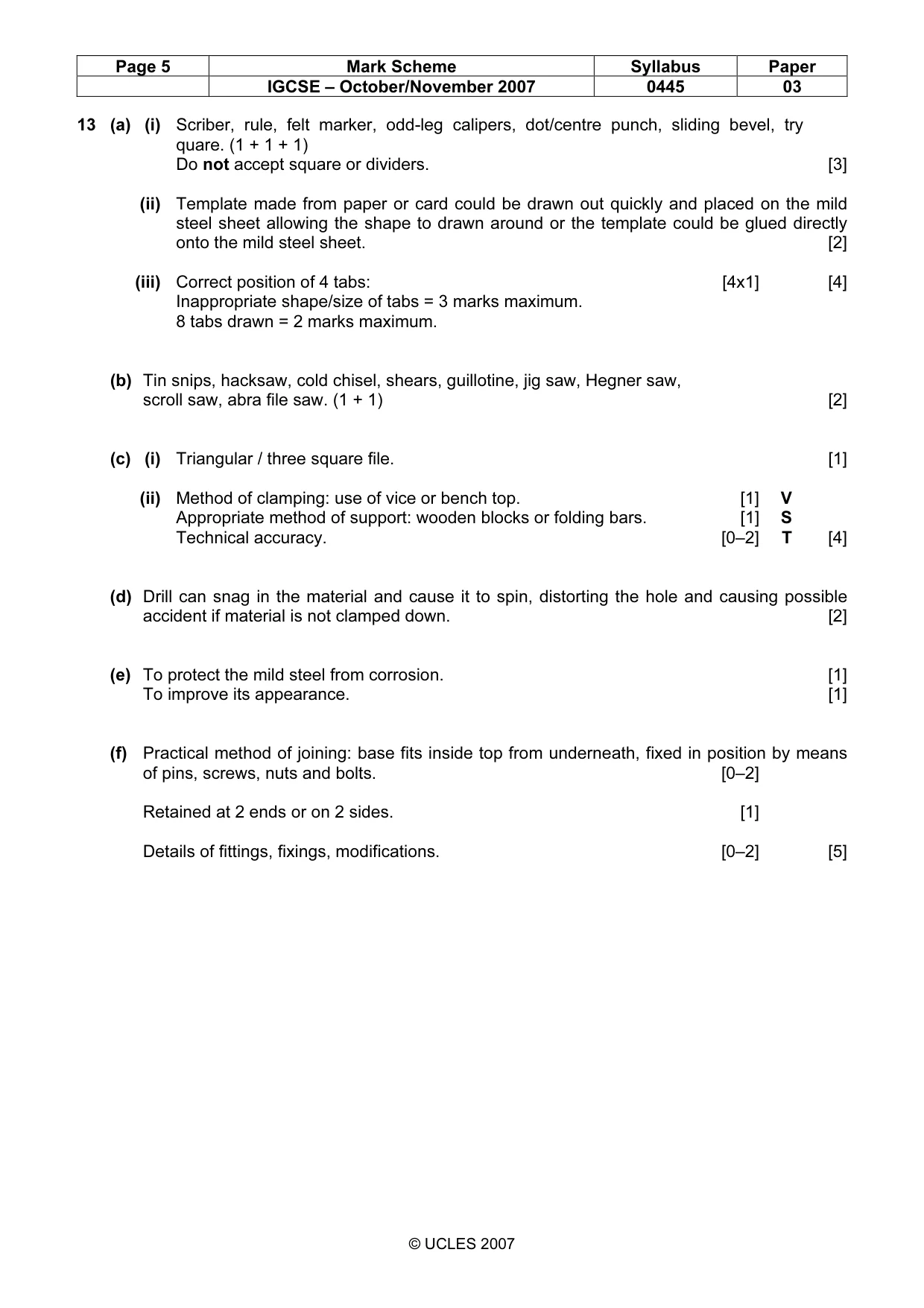
Page 5 Mark Scheme Syllabus Paper IGCSE – October/November 2007 0445 03 © UCLES 2007 13 (a) (i) Scriber, rule, felt marker, odd-leg calipers, dot/centre punch, sliding bevel, try quare. (1 + 1 + 1) Do not accept square or dividers. [3] (ii) Template made from paper or card could be drawn out quickly and placed on the mild steel sheet allowing the shape to drawn around or the template could be glued directly onto the mild steel sheet. [2] (iii) Correct position of 4 tabs: [4x1] [4] Inappropriate shape/size of tabs = 3 marks maximum. 8 tabs drawn = 2 marks maximum. (b) Tin snips, hacksaw, cold chisel, shears, guillotine, jig saw, Hegner saw, scroll saw, abra file saw. (1 + 1) [2] (c) (i) Triangular / three square file. [1] (ii) Method of clamping: use of vice or bench top. [1] V Appropriate method of support: wooden blocks or folding bars. [1] S Technical accuracy. [0–2] T [4] (d) Drill can snag in the material and cause it to spin, distorting the hole and causing possible accident if material is not clamped down. [2] (e) To protect the mild steel from corrosion. [1] To improve its appearance. [1] (f) Practical method of joining: base fits inside top from underneath, fixed in position by means of pins, screws, nuts and bolts. [0–2] Retained at 2 ends or on 2 sides. [1] Details of fittings, fixings, modifications. [0–2] [5]
What you needed in this session
Cambridge’s own grade thresholds for 2007 Oct/Nov, Paper 3 · Variant 1. A higher threshold means an easier paper — the bar moves with how the cohort did.