Cambridge IGCSE Design and Technology 0445 — 2006 Oct/Nov Paper 3 · Variant 1
0445/31/O/N/06
The question paper and its mark scheme, free to read here and free to download. This is Cambridge’s own paper, exactly as it was sat.
Question paper20 pages

Mark scheme4 pages
Answers below. Sit the paper first if you are practising.
Paper as text
Question paper, page 1
Centre Number Candidate Number Name UNIVERSITY OF CAMBRIDGE INTERNATIONAL EXAMINATIONS International General Certificate of Secondary Education DESIGN AND TECHNOLOGY 0445/03 Paper 3 Realisation October/November 2006 1 hour Candidates answer on the Question Paper. No Additional Materials are required. To be taken together with Paper 1 in one session of 2 hours 45 minutes. READ THESE INSTRUCTIONS FIRST Write your Centre number, candidate number and name on all the work you hand in. Write in dark blue or black pen. You may use a soft pencil for any diagrams, graphs or rough working. Do not use staples, paper clips, highlighters, glue or correction fluid. Answer two questions. You may use a calculator. The number of marks is given in brackets [ ] at the end of each question or part questions. At the end of the examination, fasten all your work securely together. FOR EXAMINER’S USE 1 2 3 4 TOTAL This document consists of 18 printed pages and 2 blank pages. IB06 11_0445_03/3RP UCLES 2006 [Turn over www.XtremePapers.com
Question paper, page 2
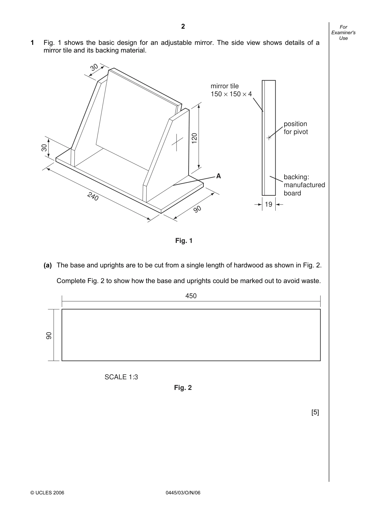
2 © UCLES 2006 0445/03/O/N/06 For Examiner's Use 1 Fig. 1 shows the basic design for an adjustable mirror. The side view shows details of a mirror tile and its backing material. 30 120 30 90 240 A Fig. 1 mirror tile 150 × 150 × 4 position for pivot backing: manufactured board 19 (a) The base and uprights are to be cut from a single length of hardwood as shown in Fig. 2. Complete Fig. 2 to show how the base and uprights could be marked out to avoid waste. 450 90 SCALE 1:3 Fig. 2 [5]
Question paper, page 3
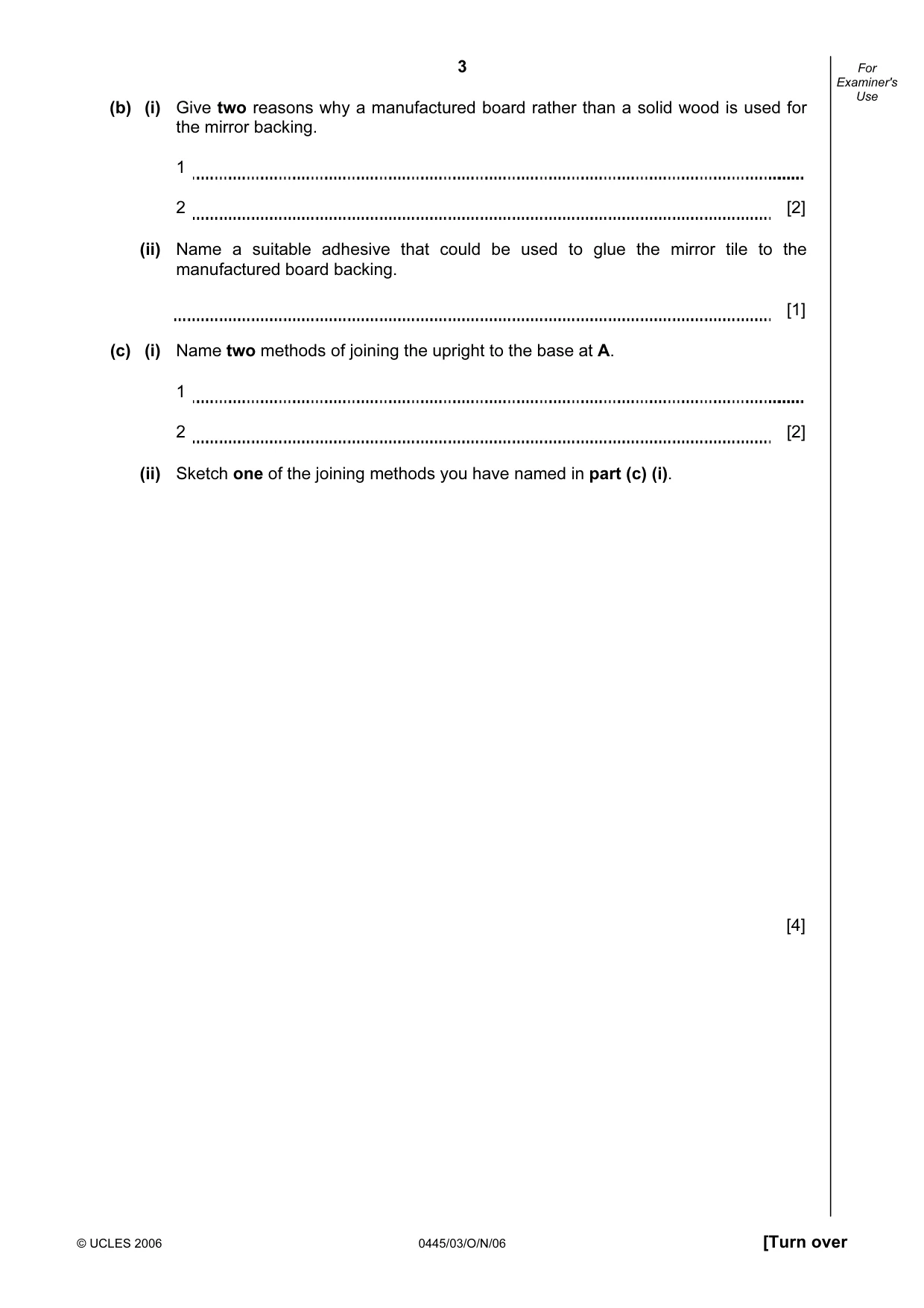
3 © UCLES 2006 0445/03/O/N/06 [Turn over For Examiner's Use (b) (i) Give two reasons why a manufactured board rather than a solid wood is used for the mirror backing. 1 2 [2] (ii) Name a suitable adhesive that could be used to glue the mirror tile to the manufactured board backing. [1] (c) (i) Name two methods of joining the upright to the base at A. 1 2 [2] (ii) Sketch one of the joining methods you have named in part (c) (i). [4]
Question paper, page 4
4 © UCLES 2006 0445/03/O/N/06 For Examiner's Use (iii) Use notes and sketches to show four of the main stages in making one of the joints named in part (c) (i). Do not include marking out. Chosen joint Stage 1 [2] Stage 2 [2] Stage 3 [2] Stage 4 [2]
Question paper, page 5
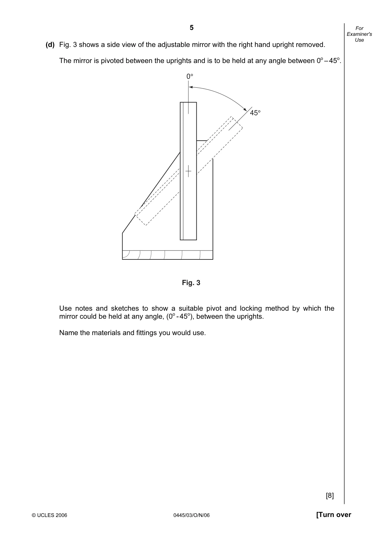
5 © UCLES 2006 0445/03/O/N/06 [Turn over For Examiner's Use (d) Fig. 3 shows a side view of the adjustable mirror with the right hand upright removed. The mirror is pivoted between the uprights and is to be held at any angle between 0o – 45o. 0° 45° Fig. 3 Use notes and sketches to show a suitable pivot and locking method by which the mirror could be held at any angle, (0o - 45o), between the uprights. Name the materials and fittings you would use. [8]
Question paper, page 6
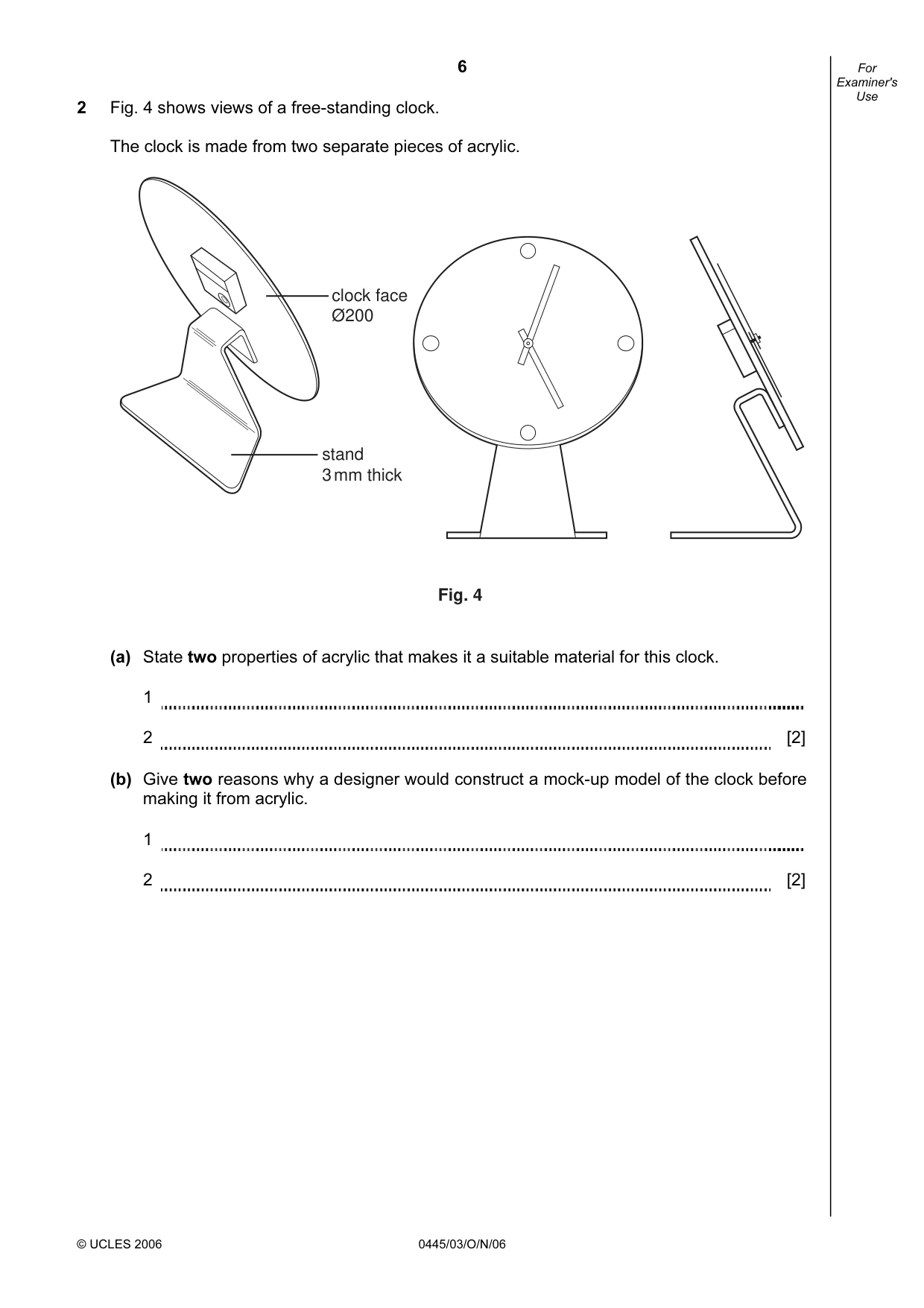
6 © UCLES 2006 0445/03/O/N/06 For Examiner's Use 2 Fig. 4 shows views of a free-standing clock. The clock is made from two separate pieces of acrylic. clock face Ø200 stand 3 mm thick Fig. 4 (a) State two properties of acrylic that makes it a suitable material for this clock. 1 2 [2] (b) Give two reasons why a designer would construct a mock-up model of the clock before making it from acrylic. 1 2 [2]
Question paper, page 7
7 © UCLES 2006 0445/03/O/N/06 [Turn over For Examiner's Use (c) Use notes and sketches to show how the clock stand could be marked out on one piece of acrylic. [8] (d) Name two tools that could be used to mark out the shape. 1 2 [2]
Question paper, page 8
8 © UCLES 2006 0445/03/O/N/06 For Examiner's Use (e) Use notes and sketches to describe the following stages when producing the two 90º bends in the clock stand. (i) Heating the plastic. [3] (ii) Bending the plastic to the required shape. [5]
Question paper, page 9
9 © UCLES 2006 0445/03/O/N/06 [Turn over For Examiner's Use (f) Describe three of the main stages in finishing the edges of the acrylic. 1 2 3 [3] (g) There is a risk that sheet acrylic could crack when being drilled. Describe how this risk can be minimised. [2] (h) (i) Name a solvent used to fix the clock face to the stand. [1] (ii) State two safety precautions you would take when using solvents. 1 2 [2]
Question paper, page 10
10 © UCLES 2006 0445/03/O/N/06 For Examiner's Use 3 Fig. 5 shows details of a table on which drinks and snacks could be placed. The table top can be adjusted to different heights. The table top has been lifted off to show the frame to which it will be attached. A table top: melamine faced manufactured board 500 400 T frame slides up and down inside the leg to provide height adjustment frame and legs: steel tube 20 square Fig. 5 (a) Name a suitable manufactured board for the table top. [1]
Question paper, page 11
11 © UCLES 2006 0445/03/O/N/06 [Turn over For Examiner's Use (b) Manufactured boards without a melamine facing require an applied finish. (i) State a suitable finish for the table top and give one reason for your choice. Finish Reason [2] (ii) Use notes and sketches to describe how the table top is prepared and your chosen finish applied. [4]
Question paper, page 12
12 © UCLES 2006 0445/03/O/N/06 For Examiner's Use (c) The table top is to be connected to the T frame by a method that allows it to be removed for maintenance. Use notes and sketches to show a suitable method. [4] (d) Use notes and sketches to show how the T frame could be adjusted and locked at three different heights. Give details of any fittings you use. [4]
Question paper, page 13
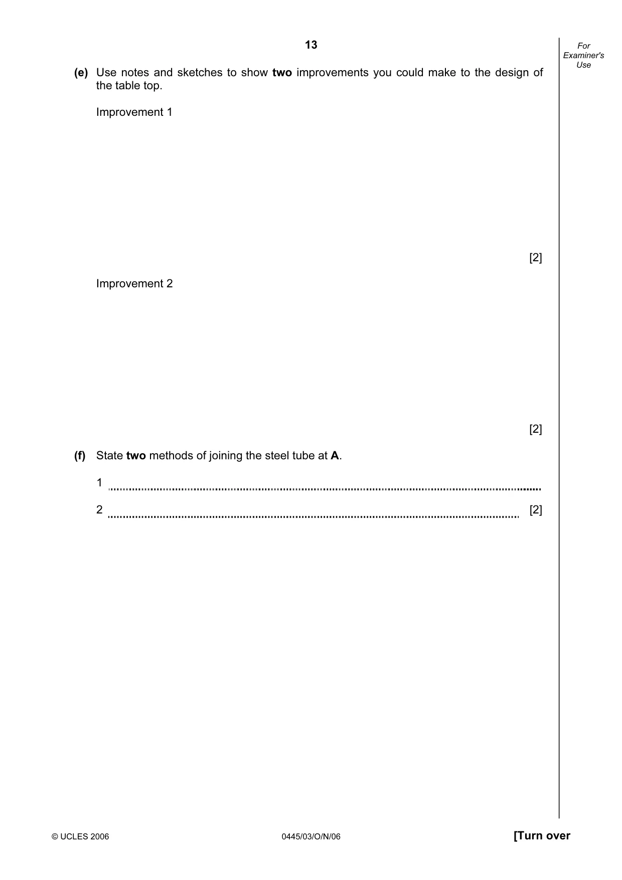
13 © UCLES 2006 0445/03/O/N/06 [Turn over For Examiner's Use (e) Use notes and sketches to show two improvements you could make to the design of the table top. Improvement 1 [2] Improvement 2 [2] (f) State two methods of joining the steel tube at A. 1 2 [2]
Question paper, page 14
14 © UCLES 2006 0445/03/O/N/06 For Examiner's Use (g) Use notes and sketches to show the following stages when making the tubular steel frame. (i) Marking the steel tube to length. [3] (ii) Cutting the steel tube to length. [3] (iii) Squaring the ends of the steel tube. [3]
Question paper, page 15
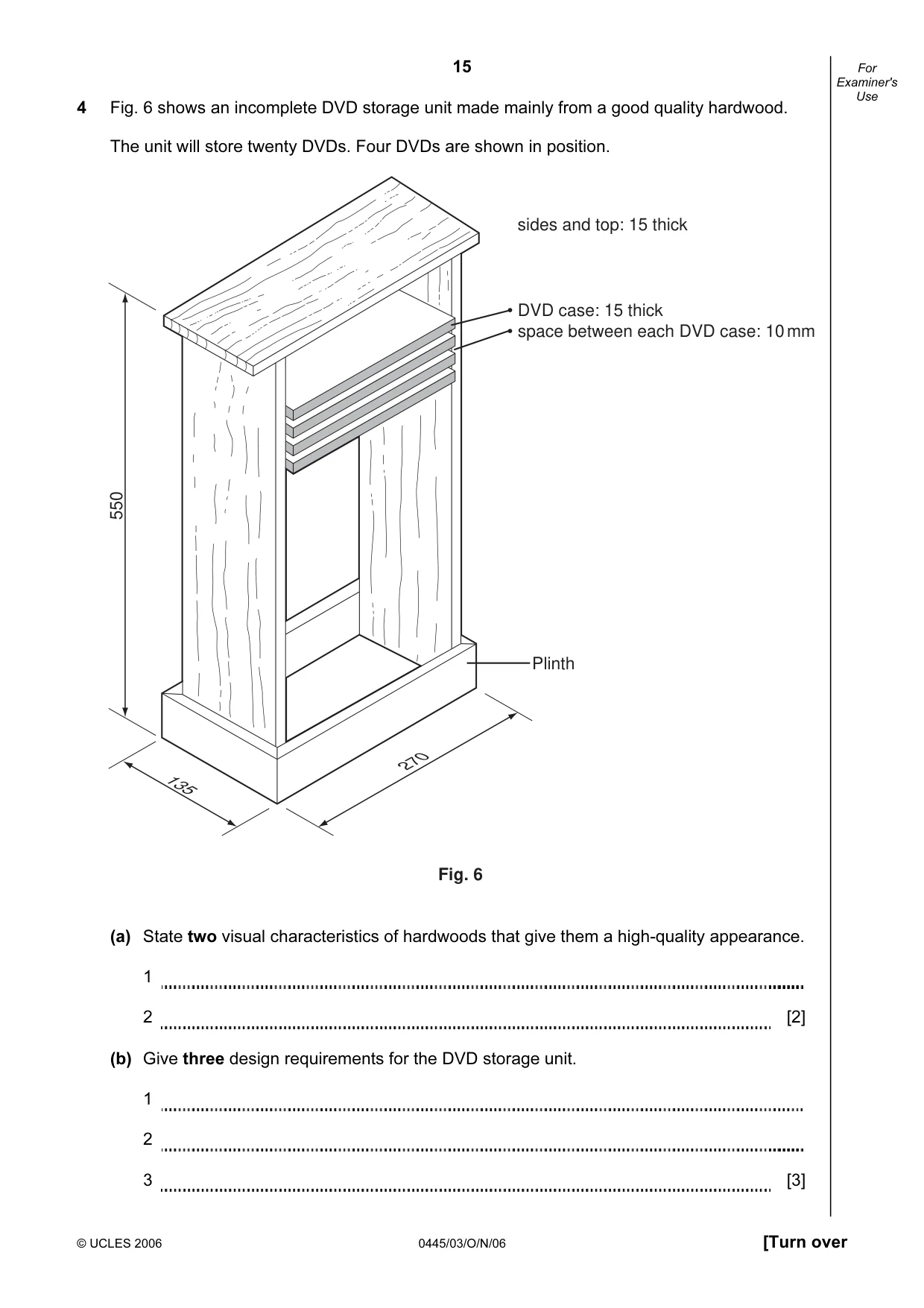
15 © UCLES 2006 0445/03/O/N/06 [Turn over For Examiner's Use 4 Fig. 6 shows an incomplete DVD storage unit made mainly from a good quality hardwood. The unit will store twenty DVDs. Four DVDs are shown in position. Plinth Fig. 6 • DVD case: 15 thick • space between each DVD case: 10 mm 270 550 135 sides and top: 15 thick (a) State two visual characteristics of hardwoods that give them a high-quality appearance. 1 2 [2] (b) Give three design requirements for the DVD storage unit. 1 2 3 [3]
Question paper, page 16
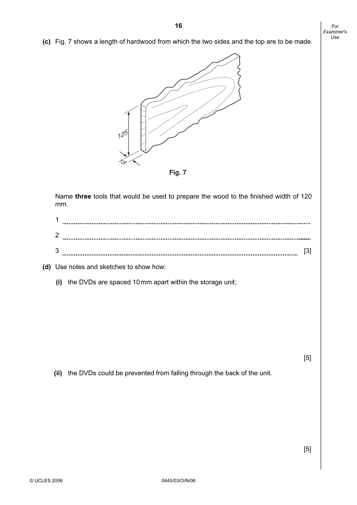
16 © UCLES 2006 0445/03/O/N/06 For Examiner's Use (c) Fig. 7 shows a length of hardwood from which the two sides and the top are to be made. Fig. 7 15 125 Name three tools that would be used to prepare the wood to the finished width of 120 mm. 1 2 3 [3] (d) Use notes and sketches to show how: (i) the DVDs are spaced 10 mm apart within the storage unit; [5] (ii) the DVDs could be prevented from falling through the back of the unit. [5]
Question paper, page 17
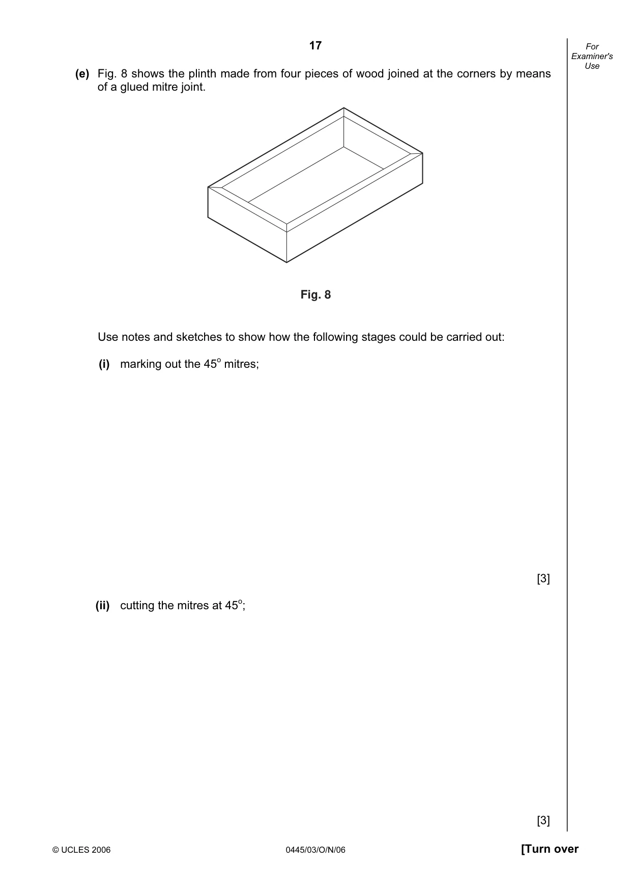
17 © UCLES 2006 0445/03/O/N/06 [Turn over For Examiner's Use (e) Fig. 8 shows the plinth made from four pieces of wood joined at the corners by means of a glued mitre joint. Fig. 8 Use notes and sketches to show how the following stages could be carried out: (i) marking out the 45o mitres; [3] (ii) cutting the mitres at 45o; [3]
Question paper, page 18
18 © UCLES 2006 0445/03/O/N/06 For Examiner's Use (iii) holding the four sides together while the glue is setting; [3] (iv) checking that the plinth is square. [3]
Question paper, page 20
20 Permission to reproduce items where third-party owned material protected by copyright is included has been sought and cleared where possible. Every reasonable effort has been made by the publisher (UCLES) to trace copyright holders, but if any items requiring clearance have unwittingly been included, the publisher will be pleased to make amends at the earliest possible opportunity. University of Cambridge International Examinations is part of the University of Cambridge Local Examinations Syndicate (UCLES), which is itself a department of the University of Cambridge. 0445/03/O/N/05 BLANK PAGE
Mark scheme, page 1
UNIVERSITY OF CAMBRIDGE INTERNATIONAL EXAMINATIONS International General Certificate of Secondary Education MARK SCHEME for the October/November 2006 question paper 0445 DESIGN AND TECHNOLOGY 0445/03 Paper 3 (Realisation), maximum raw mark 60 This mark scheme is published as an aid to teachers and students, to indicate the requirements of the examination. It shows the basis on which Examiners were instructed to award marks. It does not indicate the details of the discussions that took place at an Examiners’ meeting before marking began. All Examiners are instructed that alternative correct answers and unexpected approaches in candidates’ scripts must be given marks that fairly reflect the relevant knowledge and skills demonstrated. Mark schemes must be read in conjunction with the question papers and the report on the examination. The grade thresholds for various grades are published in the report on the examination for most IGCSE, GCE Advanced Level and Advanced Subsidiary Level syllabuses. • CIE will not enter into discussions or correspondence in connection with these mark schemes. CIE is publishing the mark schemes for the October/November 2006 question papers for most IGCSE, GCE Advanced Level and Advanced Subsidiary Level syllabuses and some Ordinary Level syllabuses. www.XtremePapers.com
Mark scheme, page 2
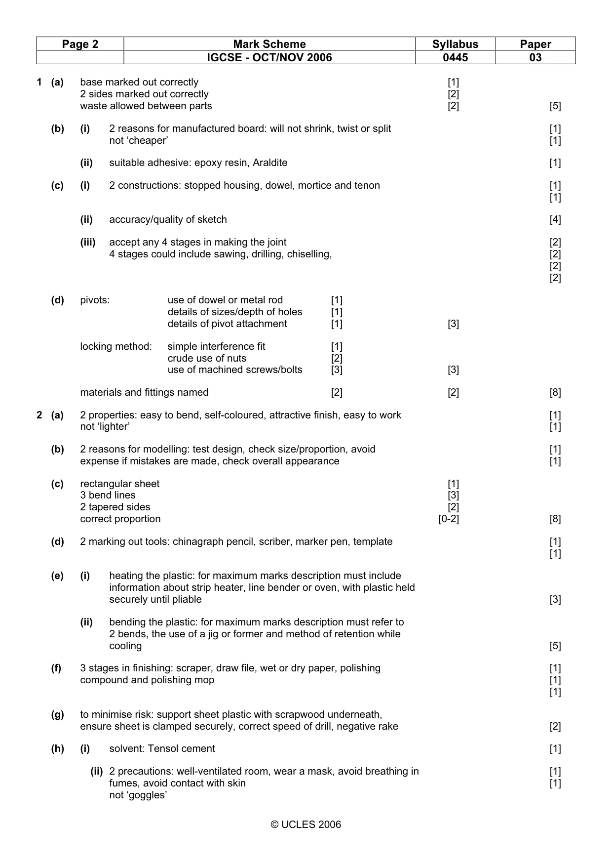
Page 2 Mark Scheme Syllabus Paper IGCSE - OCT/NOV 2006 0445 03 © UCLES 2006 1 (a) base marked out correctly [1] 2 sides marked out correctly [2] waste allowed between parts [2] [5] (b) (i) 2 reasons for manufactured board: will not shrink, twist or split [1] not ‘cheaper’ [1] (ii) suitable adhesive: epoxy resin, Araldite [1] (c) (i) 2 constructions: stopped housing, dowel, mortice and tenon [1] [1] (ii) accuracy/quality of sketch [4] (iii) accept any 4 stages in making the joint [2] 4 stages could include sawing, drilling, chiselling, [2] [2] [2] (d) pivots: use of dowel or metal rod [1] details of sizes/depth of holes [1] details of pivot attachment [1] [3] locking method: simple interference fit [1] crude use of nuts [2] use of machined screws/bolts [3] [3] materials and fittings named [2] [2] [8] 2 (a) 2 properties: easy to bend, self-coloured, attractive finish, easy to work [1] not ‘lighter’ [1] (b) 2 reasons for modelling: test design, check size/proportion, avoid [1] expense if mistakes are made, check overall appearance [1] (c) rectangular sheet [1] 3 bend lines [3] 2 tapered sides [2] correct proportion [0-2] [8] (d) 2 marking out tools: chinagraph pencil, scriber, marker pen, template [1] [1] (e) (i) heating the plastic: for maximum marks description must include information about strip heater, line bender or oven, with plastic held securely until pliable [3] (ii) bending the plastic: for maximum marks description must refer to 2 bends, the use of a jig or former and method of retention while cooling [5] (f) 3 stages in finishing: scraper, draw file, wet or dry paper, polishing [1] compound and polishing mop [1] [1] (g) to minimise risk: support sheet plastic with scrapwood underneath, ensure sheet is clamped securely, correct speed of drill, negative rake [2] (h) (i) solvent: Tensol cement [1] (ii) 2 precautions: well-ventilated room, wear a mask, avoid breathing in [1] fumes, avoid contact with skin [1] not ‘goggles’
Mark scheme, page 3
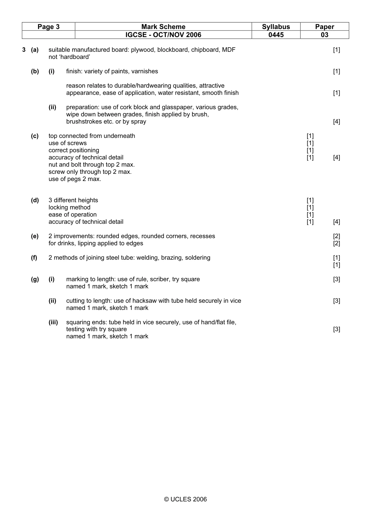
Page 3 Mark Scheme Syllabus Paper IGCSE - OCT/NOV 2006 0445 03 © UCLES 2006 3 (a) suitable manufactured board: plywood, blockboard, chipboard, MDF [1] not ‘hardboard’ (b) (i) finish: variety of paints, varnishes [1] reason relates to durable/hardwearing qualities, attractive appearance, ease of application, water resistant, smooth finish [1] (ii) preparation: use of cork block and glasspaper, various grades, wipe down between grades, finish applied by brush, brushstrokes etc. or by spray [4] (c) top connected from underneath [1] use of screws [1] correct positioning [1] accuracy of technical detail [1] [4] nut and bolt through top 2 max. screw only through top 2 max. use of pegs 2 max. (d) 3 different heights [1] locking method [1] ease of operation [1] accuracy of technical detail [1] [4] (e) 2 improvements: rounded edges, rounded corners, recesses [2] for drinks, lipping applied to edges [2] (f) 2 methods of joining steel tube: welding, brazing, soldering [1] [1] (g) (i) marking to length: use of rule, scriber, try square [3] named 1 mark, sketch 1 mark (ii) cutting to length: use of hacksaw with tube held securely in vice [3] named 1 mark, sketch 1 mark (iii) squaring ends: tube held in vice securely, use of hand/flat file, testing with try square [3] named 1 mark, sketch 1 mark
Mark scheme, page 4
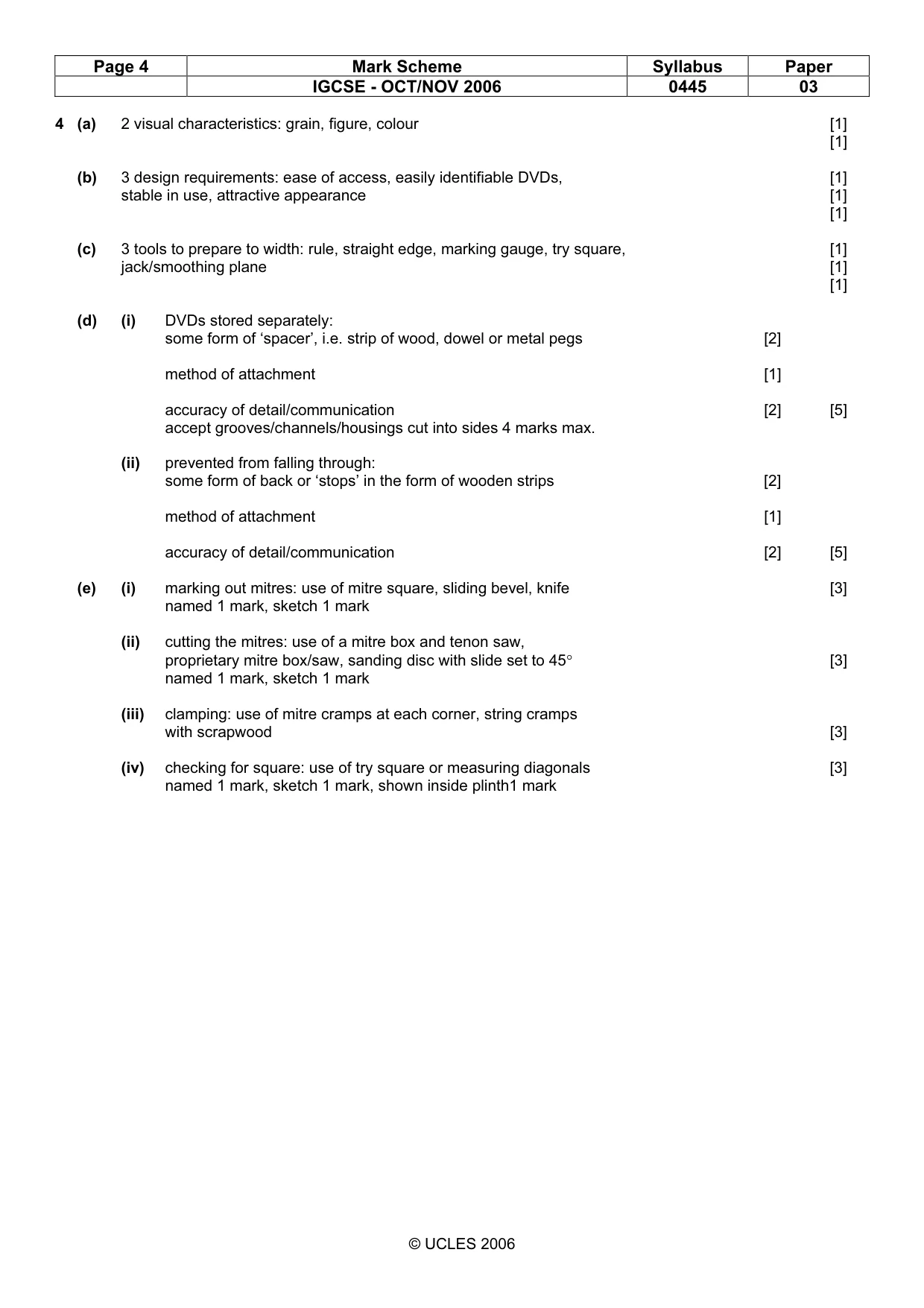
Page 4 Mark Scheme Syllabus Paper IGCSE - OCT/NOV 2006 0445 03 © UCLES 2006 4 (a) 2 visual characteristics: grain, figure, colour [1] [1] (b) 3 design requirements: ease of access, easily identifiable DVDs, [1] stable in use, attractive appearance [1] [1] (c) 3 tools to prepare to width: rule, straight edge, marking gauge, try square, [1] jack/smoothing plane [1] [1] (d) (i) DVDs stored separately: some form of ‘spacer’, i.e. strip of wood, dowel or metal pegs [2] method of attachment [1] accuracy of detail/communication [2] [5] accept grooves/channels/housings cut into sides 4 marks max. (ii) prevented from falling through: some form of back or ‘stops’ in the form of wooden strips [2] method of attachment [1] accuracy of detail/communication [2] [5] (e) (i) marking out mitres: use of mitre square, sliding bevel, knife [3] named 1 mark, sketch 1 mark (ii) cutting the mitres: use of a mitre box and tenon saw, proprietary mitre box/saw, sanding disc with slide set to 45° [3] named 1 mark, sketch 1 mark (iii) clamping: use of mitre cramps at each corner, string cramps with scrapwood [3] (iv) checking for square: use of try square or measuring diagonals [3] named 1 mark, sketch 1 mark, shown inside plinth1 mark