Cambridge A Level Physics 9702 — 2016 Oct/Nov Paper 4 · Variant 2
9702/42/O/N/16 · 14 questions · 100 marks · ≈113 min
The question paper and its mark scheme, free to read here and free to download. This is Cambridge’s own paper, exactly as it was sat.
Question paper24 pages
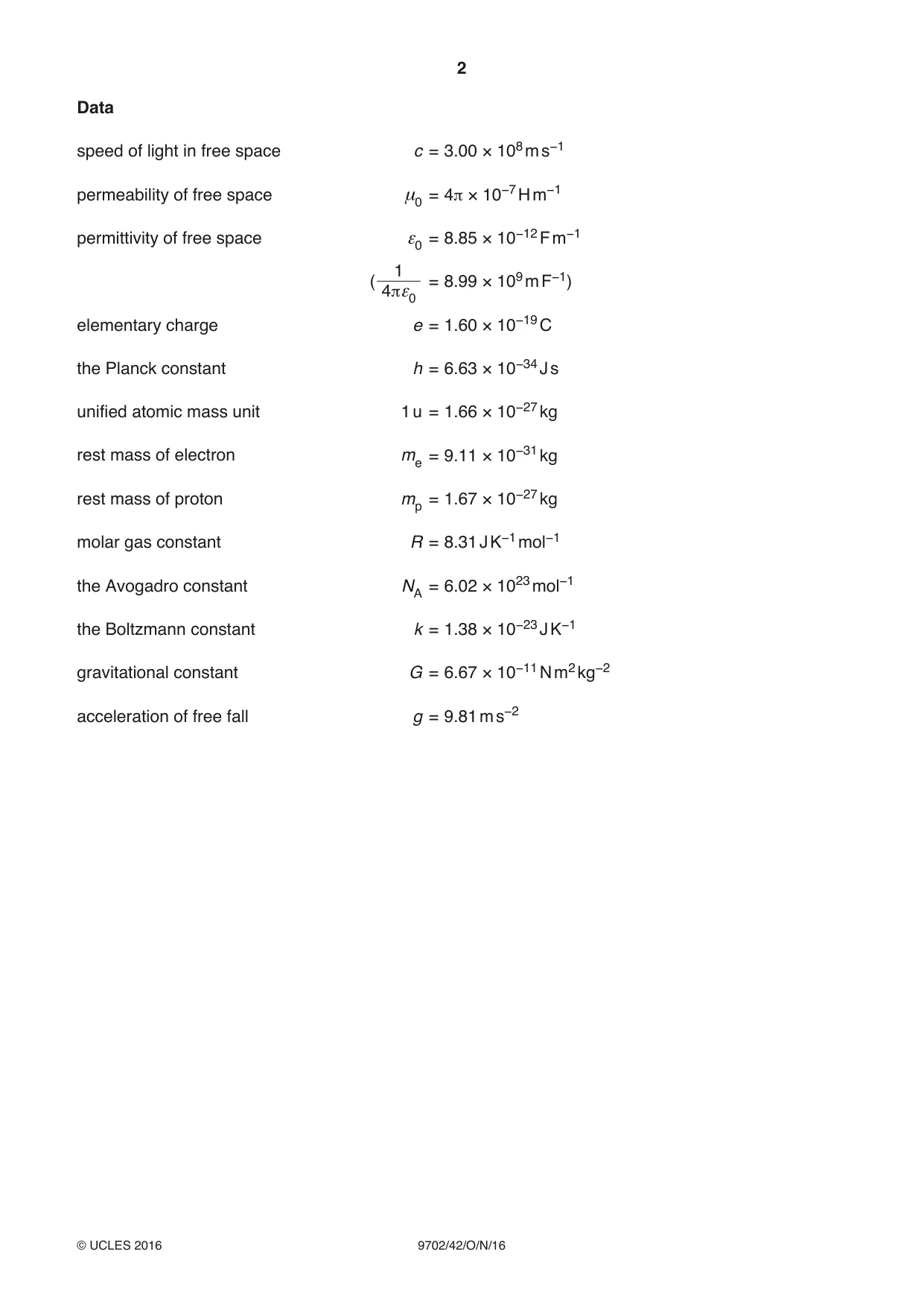
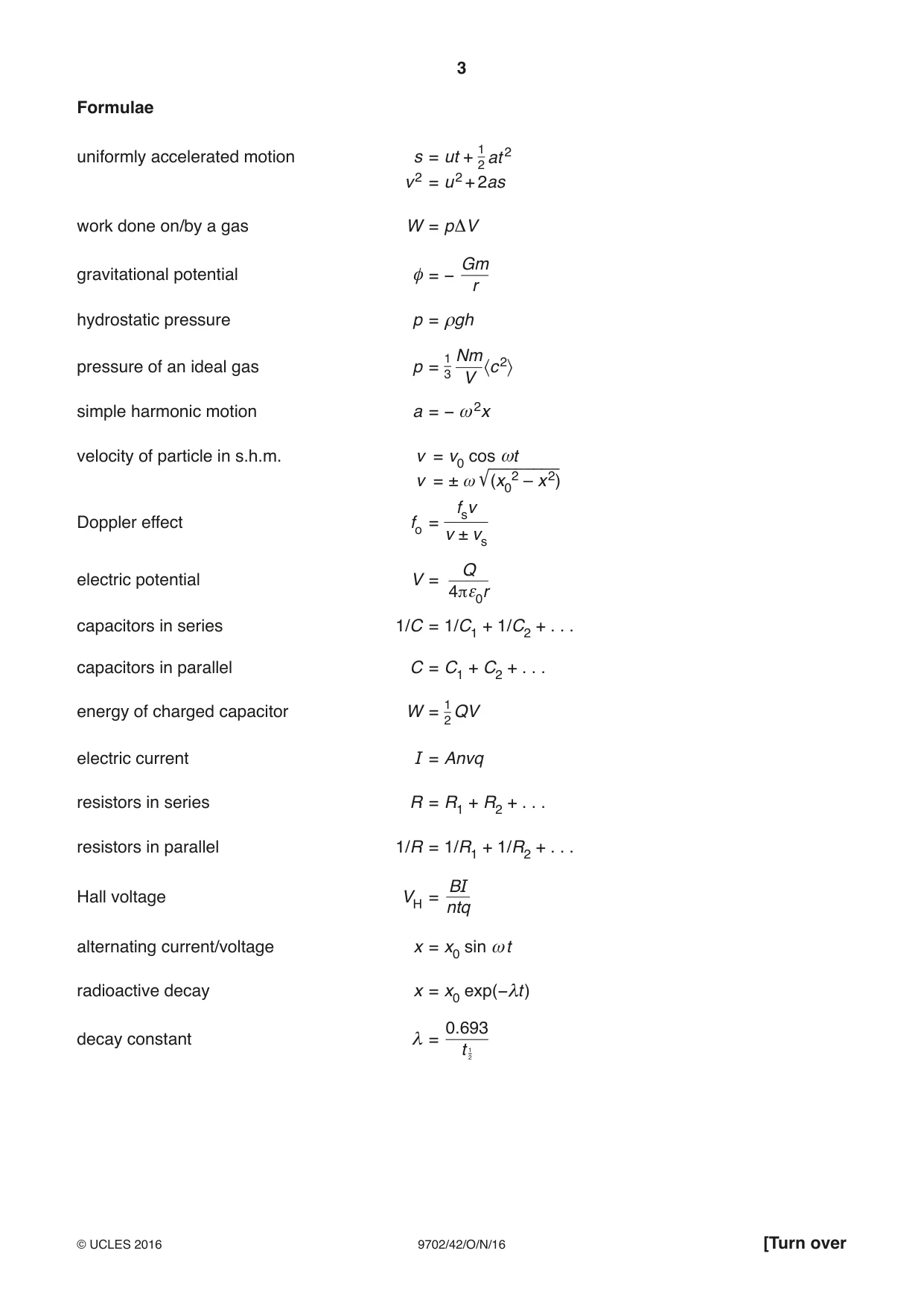

Mark scheme8 pages
Answers below. Sit the paper first if you are practising.
Questions as text
Q1 · Define gravitational field strength
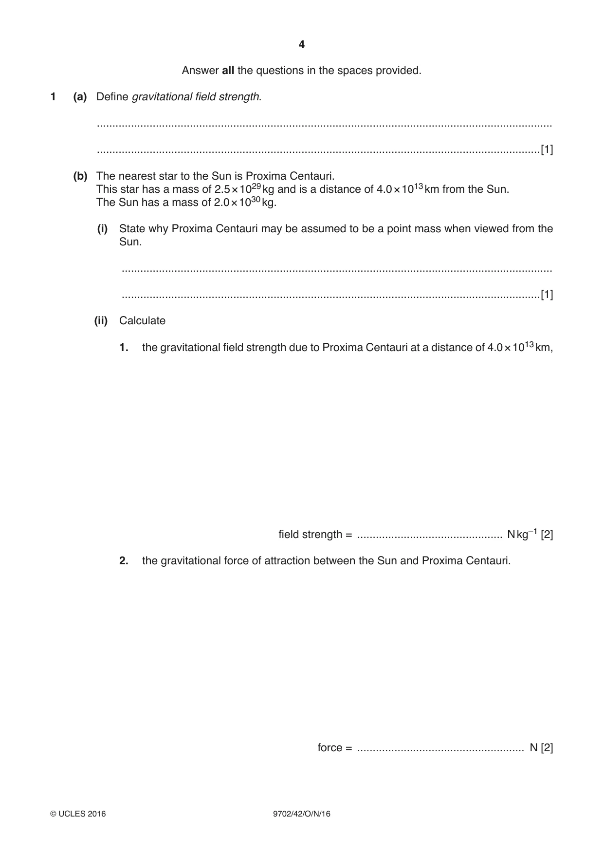
1 (a) Define gravitational field strength. ................................................................................................................................................... ...............................................................................................................................................[1] (b) The nearest star to the Sun is Proxima Centauri. This star has a mass of 2.5 × 1029 kg and is a distance of 4.0 × 10¹³ km from the Sun. The Sun has a mass of 2.0 × 1030 kg. (i) State why Proxima Centauri may be assumed to be a point mass when viewed from the Sun. ........................................................................................................................................... .......................................................................................................................................[1] (ii) Calculate 1. the gravitational field strength due to Proxima Centauri at a distance of 4.0 × 10¹³ km, field strength = ............................................... N kg–1 [2] 2. the gravitational force of attraction between the Sun and Proxima Centauri. force = ...................................................... N [2] (c) Suggest quantitatively why it may be assumed that the Sun is isolated in space from other stars. ................................................................................................................................................... ................................................................................................................................................... ...............................................................................................................................................[2] [Total: 8]
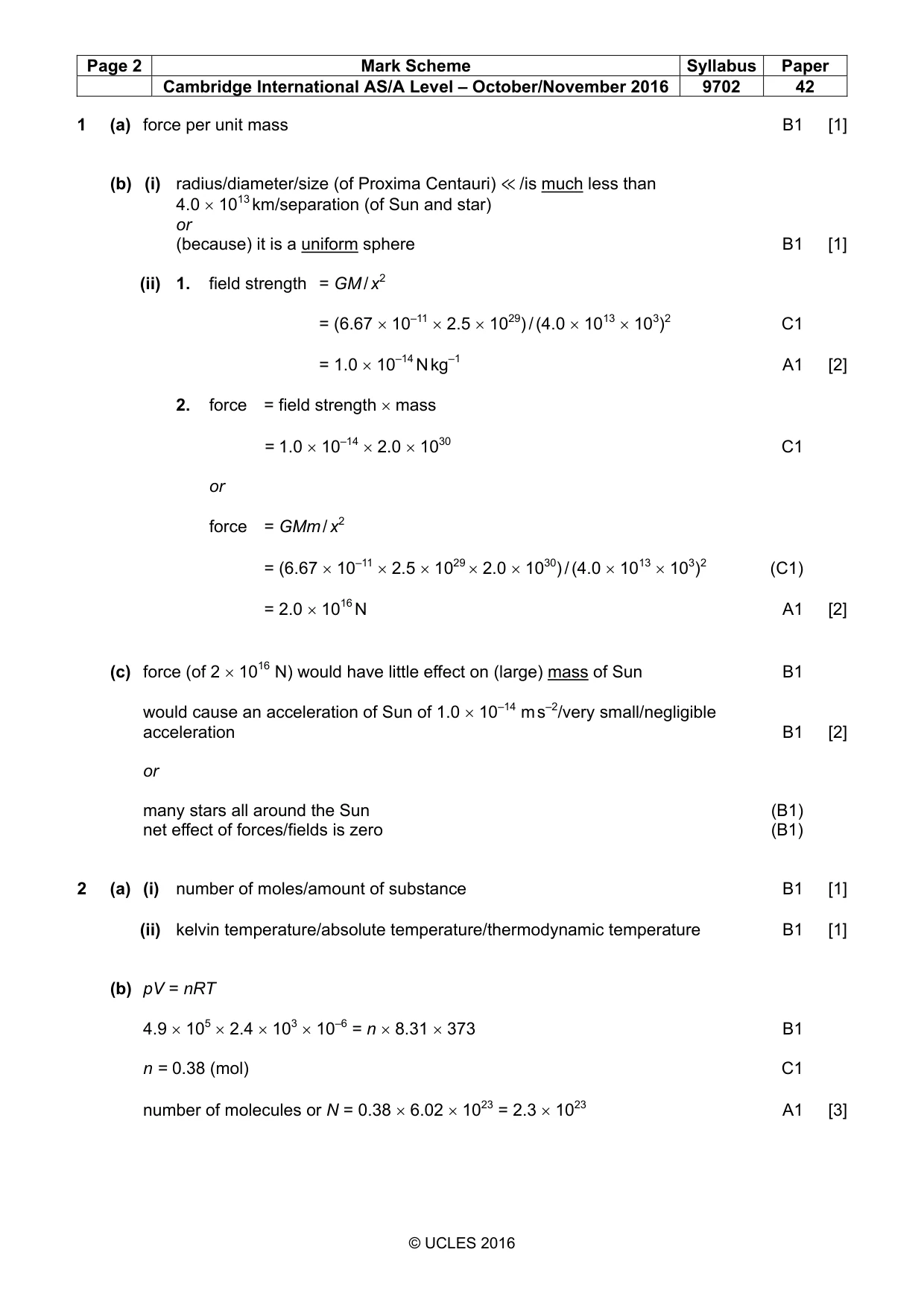
Mark scheme: 1 (a) force per unit mass B1 [1] (b) (i) radius/diameter/size (of Proxima Centauri) ≪ /is much less than 4.0 × 10¹³ km/separation (of Sun and star) or (because) it is a uniform sphere B1 [1] (ii) 1. field strength = GM / x2 = (6.67 × 10–11 × 2.5 × 1029) / (4.0 × 1013 × 103)2 C1 = 1.0 × 10⁻¹⁴ N kg–1 A1 [2] 2. force = field strength × mass = 1.0 × 10–14 × 2.0 × 1030 C1 or force = GMm / x2 = (6.67 × 10–11 × 2.5 × 1029 × 2.0 × 1030) / (4.0 × 1013 × 103)2 (C1) = 2.0 × 10¹⁶ N A1 [2] (c) force (of 2 × 10¹⁶ N) would have little effect on (large) mass of Sun B1 would cause an acceleration of Sun of 1.0 × 10⁻¹⁴ m s–2/very small/negligible acceleration B1 [2] or many stars all around the Sun (B1) net effect of forces/fields is zero (B1)
Q2 · The equation of state for an ideal gas of volume V at pressure p is pV = nRT where R is…
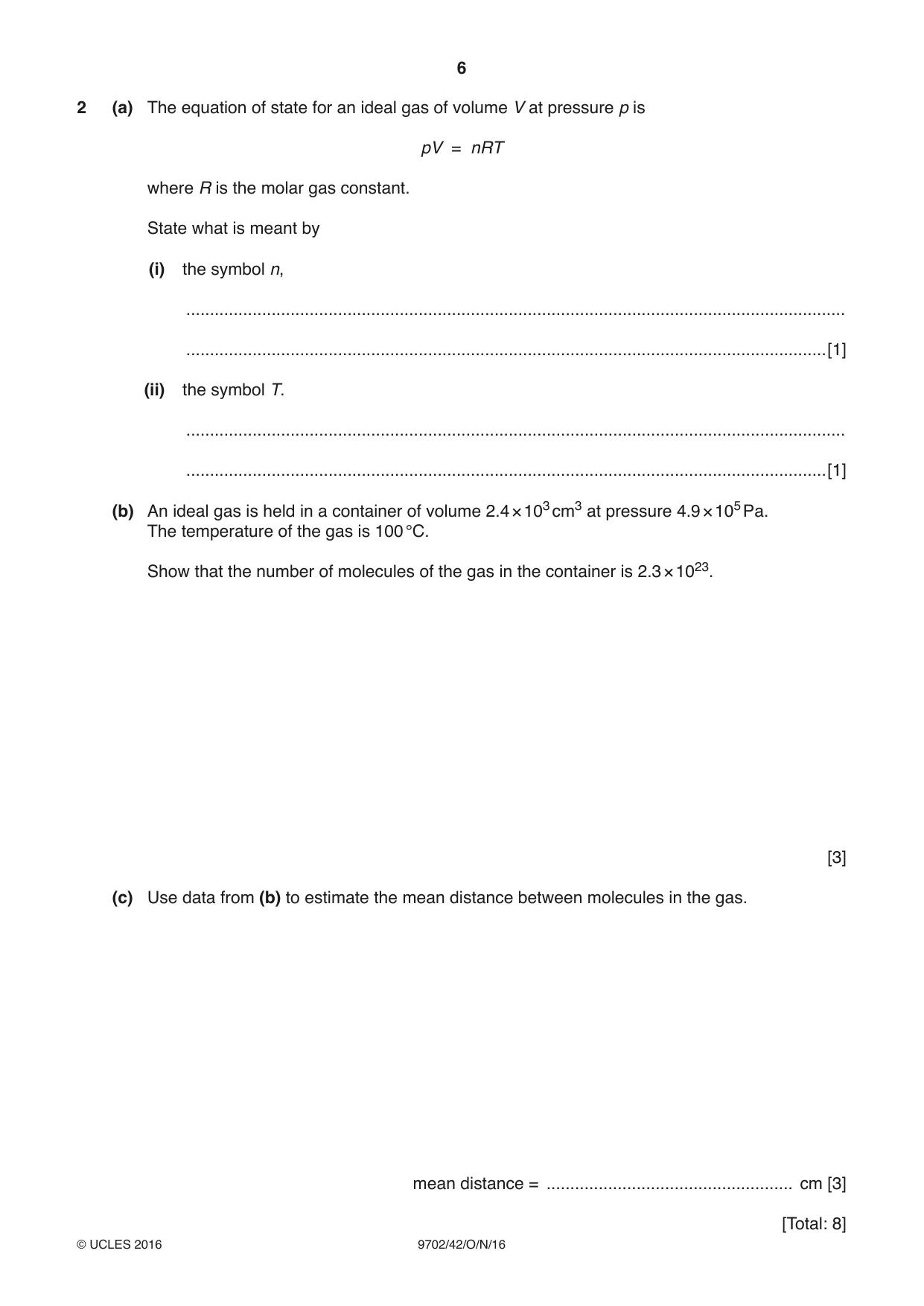
2 (a) The equation of state for an ideal gas of volume V at pressure p is pV = nRT where R is the molar gas constant. State what is meant by (i) the symbol n, ........................................................................................................................................... .......................................................................................................................................[1] (ii) the symbol T. ........................................................................................................................................... .......................................................................................................................................[1] (b) An ideal gas is held in a container of volume 2.4 × 103 cm3 at pressure 4.9 × 10⁵ Pa. The temperature of the gas is 100 °C. Show that the number of molecules of the gas in the container is 2.3 × 10²³. [3] (c) Use data from (b) to estimate the mean distance between molecules in the gas. mean distance = .................................................... cm [3] [Total: 8]
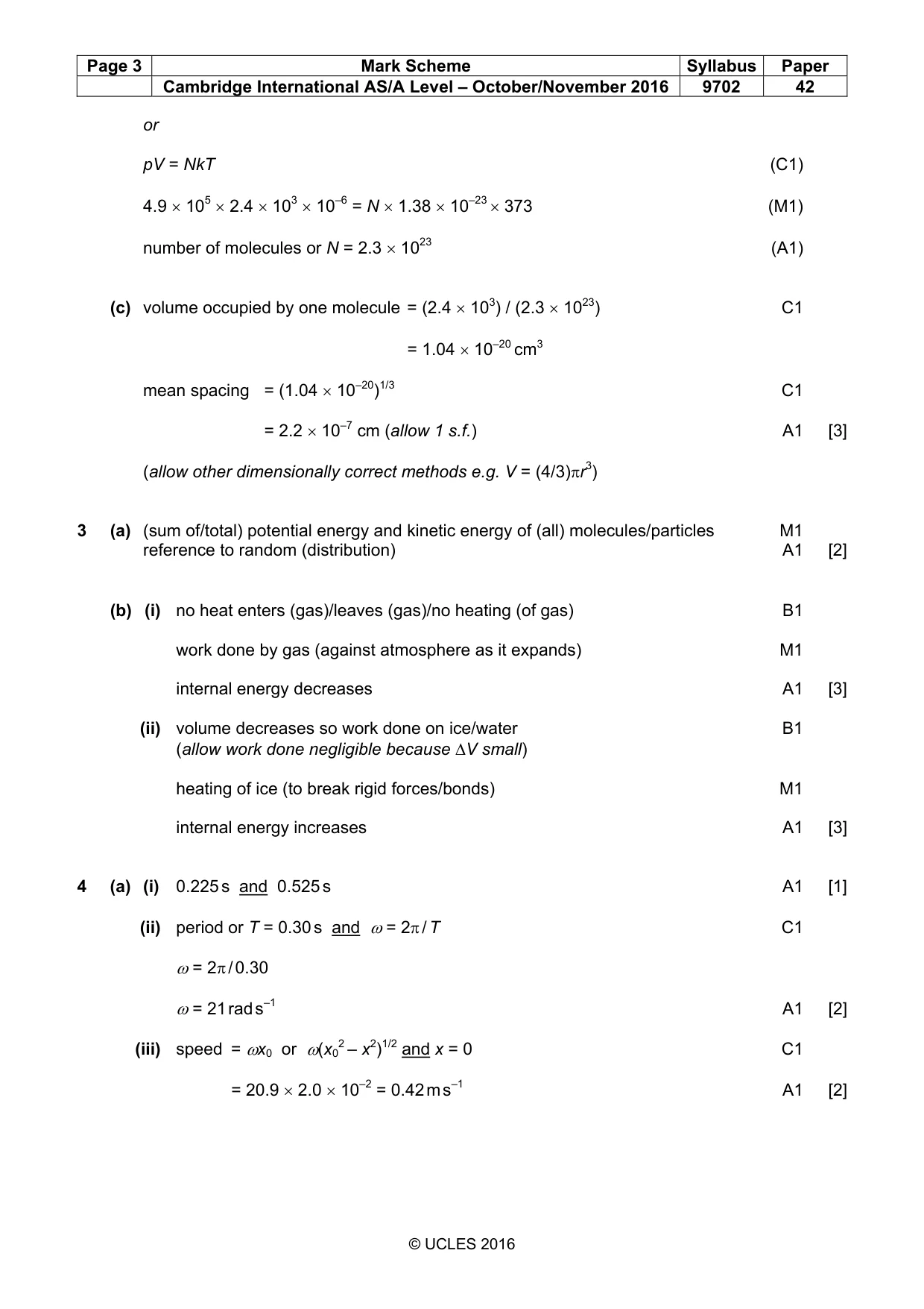
Mark scheme: 2 (a) (i) number of moles/amount of substance B1 [1] (ii) kelvin temperature/absolute temperature/thermodynamic temperature B1 [1] (b) pV = nRT 4.9 × 105 × 2.4 × 103 × 10–6 = n × 8.31 × 373 B1 n = 0.38 (mol) C1 number of molecules or N = 0.38 × 6.02 × 1023 = 2.3 × 10²³ A1 [3] or pV = NkT (C1) 4.9 × 105 × 2.4 × 103 × 10–6 = N × 1.38 × 10–23 × 373 (M1) number of molecules or N = 2.3 × 10²³ (A1) (c) volume occupied by one molecule = (2.4 × 10³) / (2.3 × 10²³) C1 = 1.04 × 10⁻²⁰ cm3 mean spacing = (1.04 × 10⁻²⁰)1/3 C1 = 2.2 × 10⁻⁷ cm (allow 1 s.f.) A1 [3] (allow other dimensionally correct methods e.g. V = (4/3)πr3)
Q3 · State what is meant by the internal energy of a system
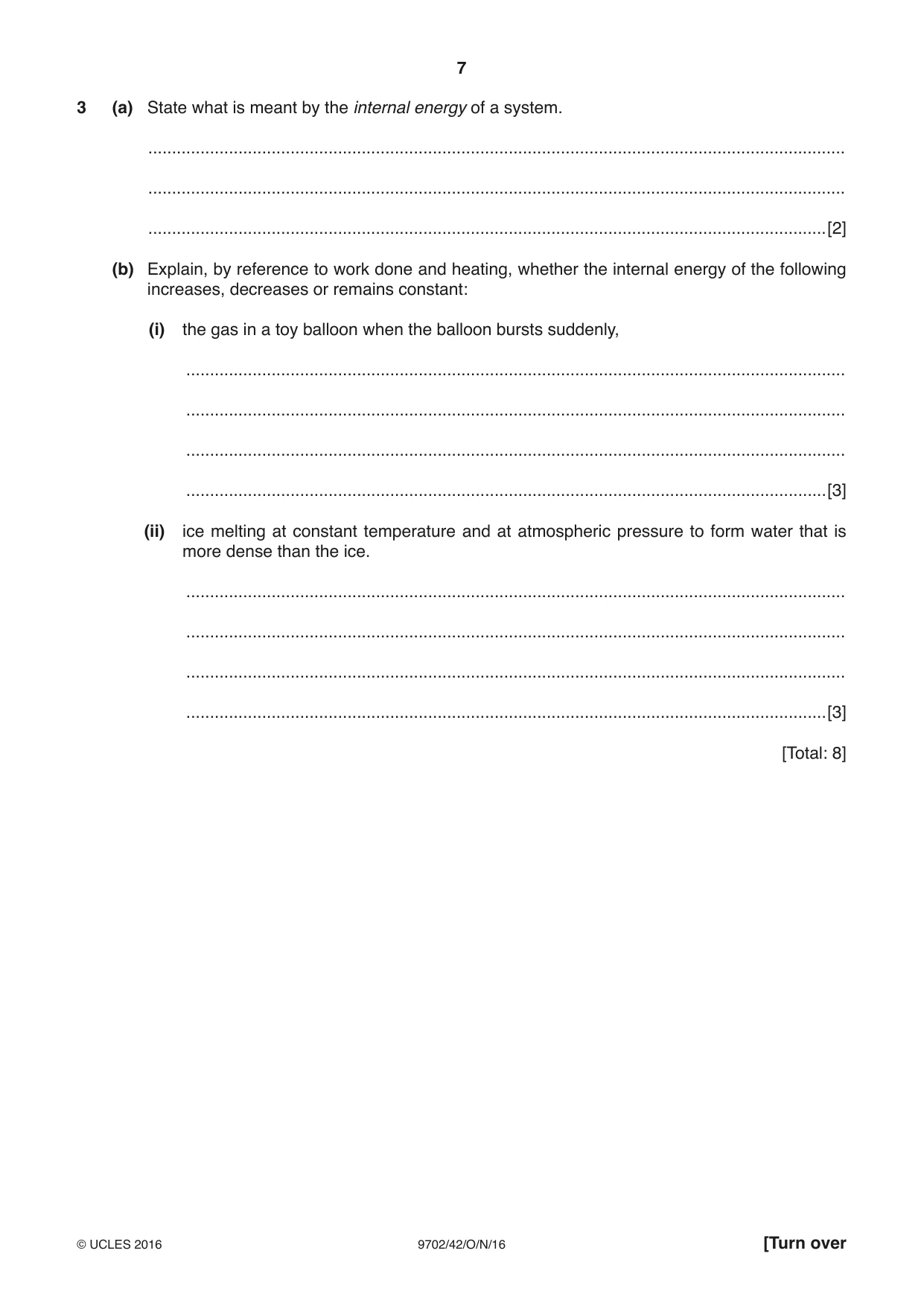
3 (a) State what is meant by the internal energy of a system. ................................................................................................................................................... ................................................................................................................................................... ...............................................................................................................................................[2] (b) Explain, by reference to work done and heating, whether the internal energy of the following increases, decreases or remains constant: (i) the gas in a toy balloon when the balloon bursts suddenly, ........................................................................................................................................... ........................................................................................................................................... ........................................................................................................................................... .......................................................................................................................................[3] (ii) ice melting at constant temperature and at atmospheric pressure to form water that is more dense than the ice. ........................................................................................................................................... ........................................................................................................................................... ........................................................................................................................................... .......................................................................................................................................[3] [Total: 8]
Mark scheme: 3 (a) (sum of/total) potential energy and kinetic energy of (all) molecules/particles M1 reference to random (distribution) A1 [2] (b) (i) no heat enters (gas)/leaves (gas)/no heating (of gas) B1 work done by gas (against atmosphere as it expands) M1 internal energy decreases A1 [3] (ii) volume decreases so work done on ice/water B1 (allow work done negligible because ∆V small) heating of ice (to break rigid forces/bonds) M1 internal energy increases A1 [3]
Q4 · A mass hangs vertically from a fixed point by means of a spring, as shown in Fig
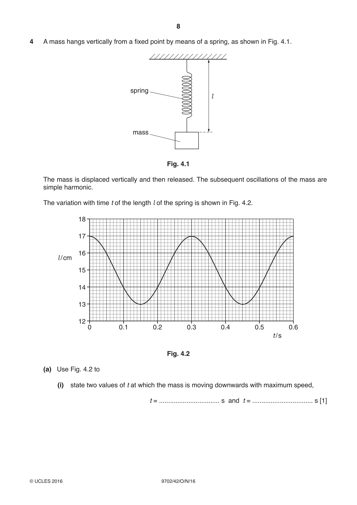
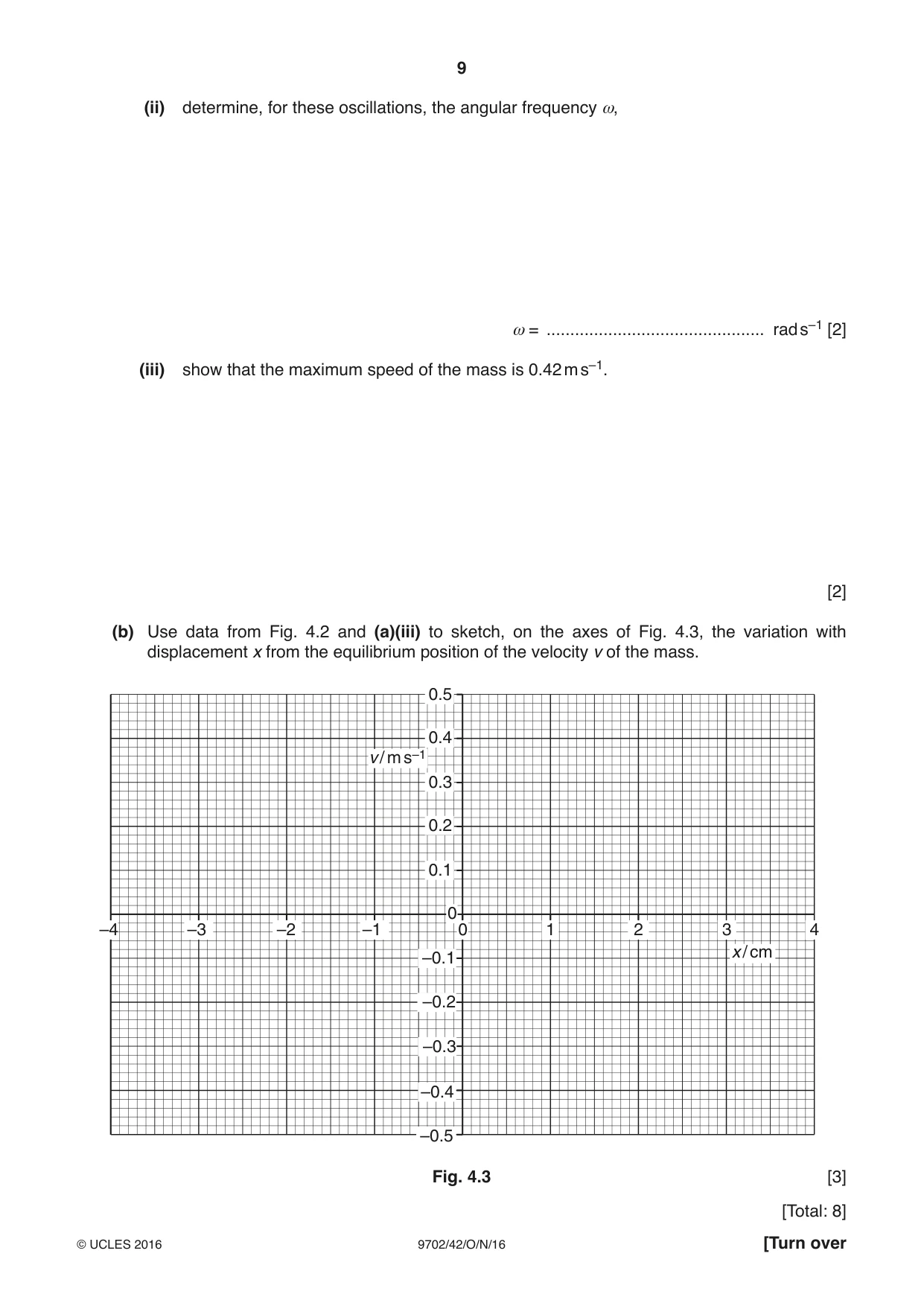
4 A mass hangs vertically from a fixed point by means of a spring, as shown in Fig. 4.1. spring l mass Fig. 4.1 The mass is displaced vertically and then released. The subsequent oscillations of the mass are simple harmonic. The variation with time t of the length l of the spring is shown in Fig. 4.2. 18 17 16 l / cm 15 14 13 12 0 0.1 0.2 0.3 0.4 0.5 0.6 t / s Fig. 4.2 (a) Use Fig. 4.2 to (i) state two values of t at which the mass is moving downwards with maximum speed, t = ................................. s and t = ................................. s [1] (ii) determine, for these oscillations, the angular frequency ω, ω = .............................................. rad s–1 [2] (iii) show that the maximum speed of the mass is 0.42 m s–1. [2] (b) Use data from Fig. 4.2 and (a)(iii) to sketch, on the axes of Fig. 4.3, the variation with displacement x from the equilibrium position of the velocity v of the mass. 0.5 0.4 v / m s–1 0.3 0.2 0.1 0 –4 –3 –2 –1 0 1 2 3 4 x / cm –0.1 –0.2 –0.3 –0.4 –0.5 Fig. 4.3 [3] [Total: 8]
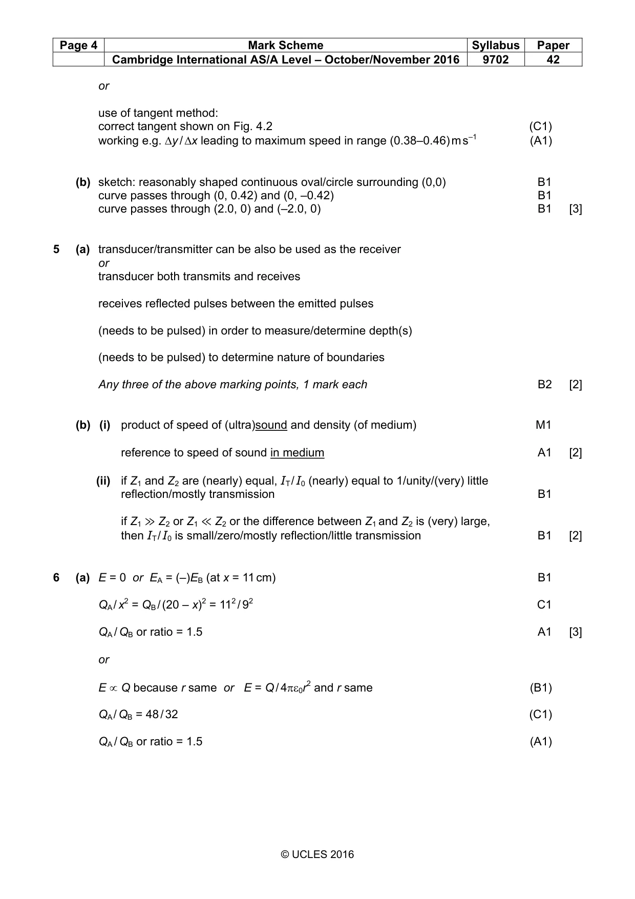
Mark scheme: 4 (a) (i) 0.225 s and 0.525 s A1 [1] (ii) period or T = 0.30 s and ω= 2π / T C1 ω= 2π / 0.30 ω= 21 rad s–1 A1 [2] (iii) speed = ωx0 or ω(x02 – x2)1/2 and x = 0 C1 = 20.9 × 2.0 × 10–2 = 0.42 m s–1 A1 [2] or use of tangent method: correct tangent shown on Fig. 4.2 (C1) working e.g. ∆y / ∆x leading to maximum speed in range (0.38–0.46) m s–1 (A1) (b) sketch: reasonably shaped continuous oval/circle surrounding (0,0) B1 curve passes through (0, 0.42) and (0, –0.42) B1 curve passes through (2.0, 0) and (–2.0, 0) B1 [3]
Q5 · Ultrasound may be used to obtain information about internal body structures
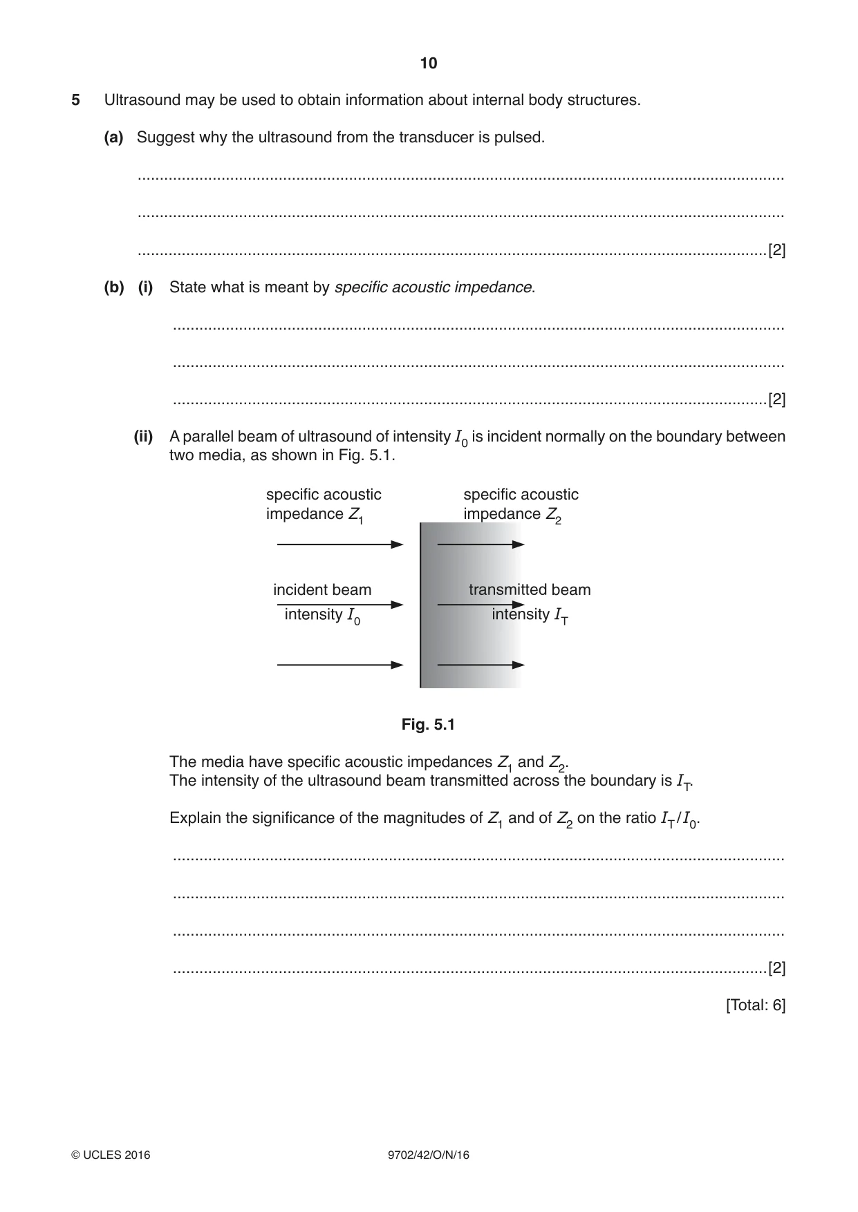
5 Ultrasound may be used to obtain information about internal body structures. (a) Suggest why the ultrasound from the transducer is pulsed. ................................................................................................................................................... ................................................................................................................................................... ...............................................................................................................................................[2] (b) (i) State what is meant by specific acoustic impedance. ........................................................................................................................................... ........................................................................................................................................... .......................................................................................................................................[2] (ii) A parallel beam of ultrasound of intensity I0 is incident normally on the boundary between two media, as shown in Fig. 5.1. specific acoustic specific acoustic impedance Z1 impedance Z2 incident beam transmitted beam intensity I0 intensity IT Fig. 5.1 The media have specific acoustic impedances Z1 and Z2. The intensity of the ultrasound beam transmitted across the boundary is IT. Explain the significance of the magnitudes of Z1 and of Z2 on the ratio IT / I0. ........................................................................................................................................... ........................................................................................................................................... ........................................................................................................................................... .......................................................................................................................................[2] [Total: 6]
Mark scheme: 5 (a) transducer/transmitter can be also be used as the receiver or transducer both transmits and receives receives reflected pulses between the emitted pulses (needs to be pulsed) in order to measure/determine depth(s) (needs to be pulsed) to determine nature of boundaries Any three of the above marking points, 1 mark each B2 [2] (b) (i) product of speed of (ultra)sound and density (of medium) M1 reference to speed of sound in medium A1 [2] (ii) if Z1 and Z2 are (nearly) equal, IT / I0 (nearly) equal to 1/unity/(very) little reflection/mostly transmission B1 if Z1 ≫ Z2 or Z1 ≪ Z2 or the difference between Z1 and Z2 is (very) large, then IT / I0 is small/zero/mostly reflection/little transmission B1 [2]
Q6 · Two solid metal spheres A and B, each of radius 1.5 cm, are situated in a vacuum
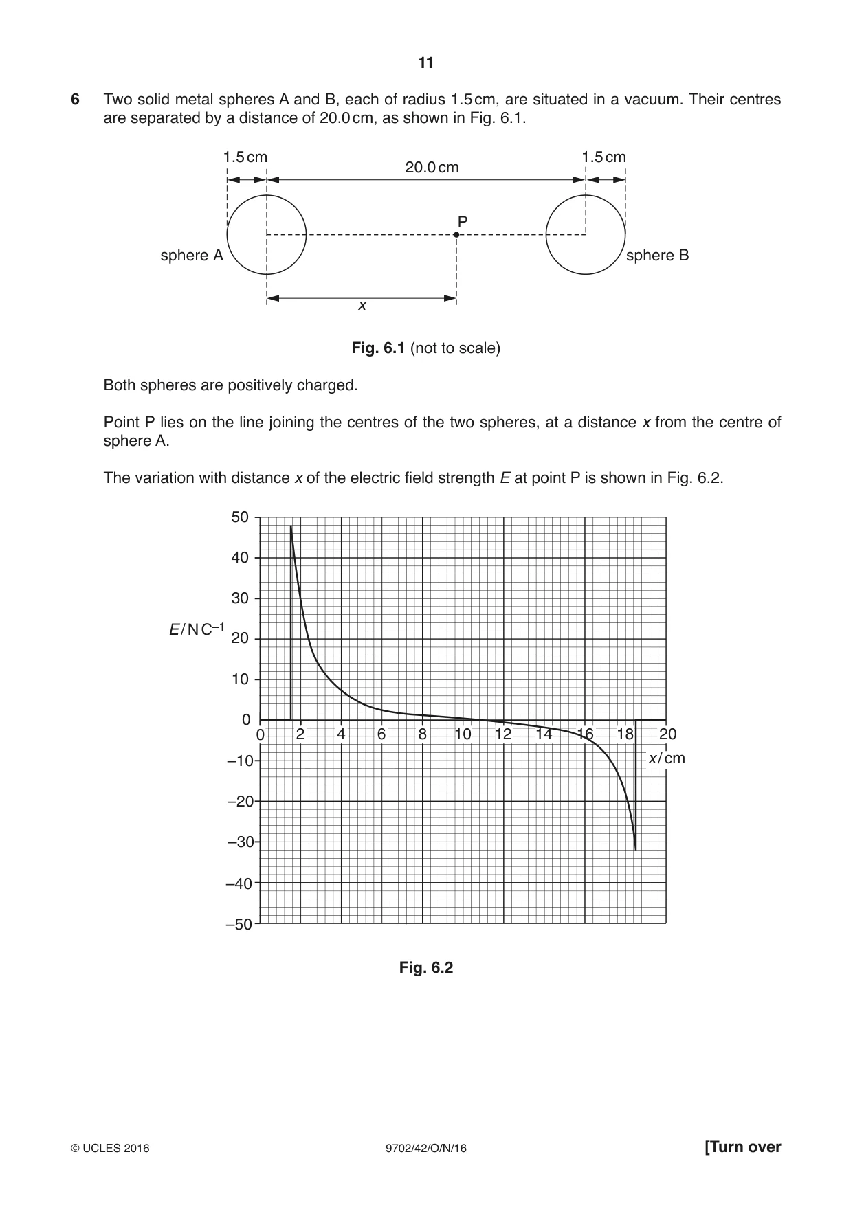
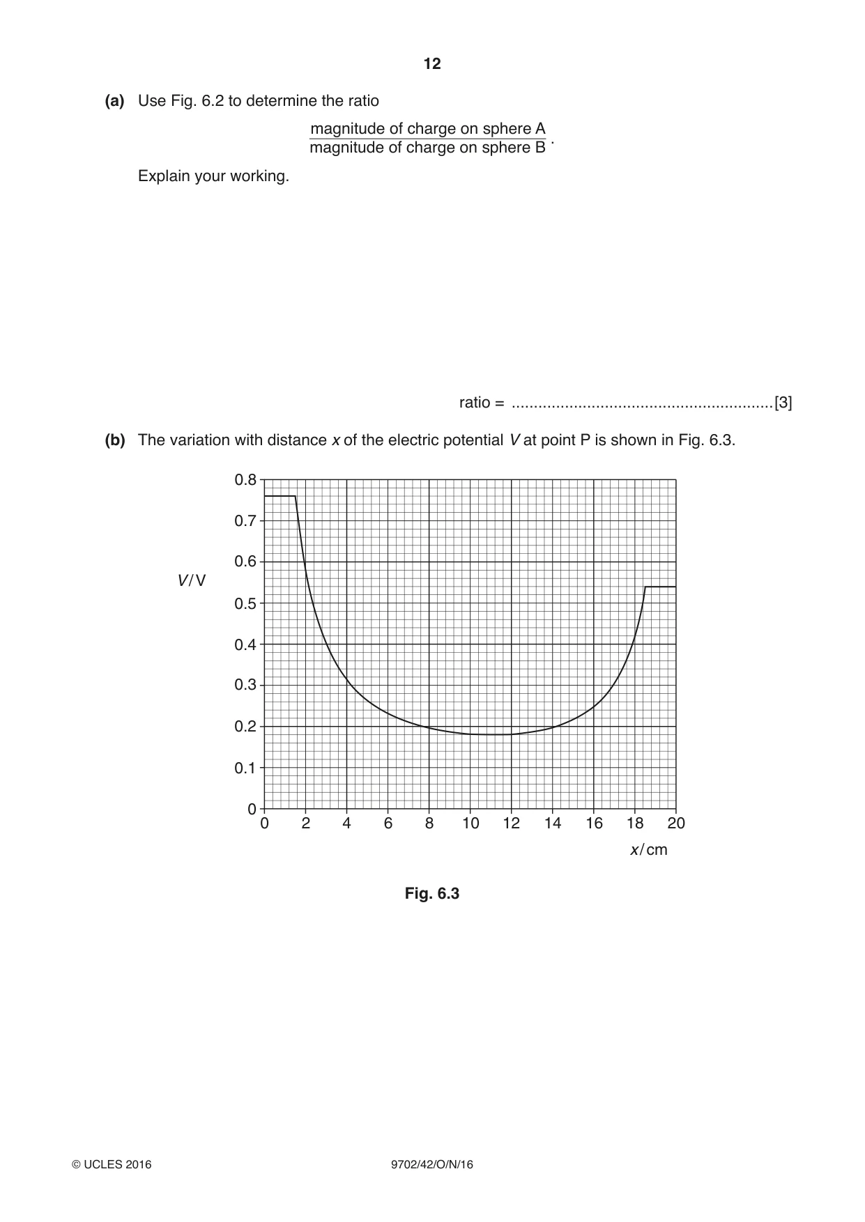
6 Two solid metal spheres A and B, each of radius 1.5 cm, are situated in a vacuum. Their centres are separated by a distance of 20.0 cm, as shown in Fig. 6.1. 1.5 cm 1.5 cm 20.0 cm P sphere A sphere B x Fig. 6.1 (not to scale) Both spheres are positively charged. Point P lies on the line joining the centres of the two spheres, at a distance x from the centre of sphere A. The variation with distance x of the electric field strength E at point P is shown in Fig. 6.2. 50 40 30 E / N C–1 20 10 0 0 2 4 6 8 10 12 14 16 18 20 –10 x / cm –20 –30 –40 –50 Fig. 6.2 (a) Use Fig. 6.2 to determine the ratio magnitude of charge on sphere A . magnitude of charge on sphere B Explain your working. ratio = ...........................................................[3] (b) The variation with distance x of the electric potential V at point P is shown in Fig. 6.3. 0.8 0.7 0.6 V / V 0.5 0.4 0.3 0.2 0.1 0 0 2 4 6 8 10 12 14 16 18 20 x / cm Fig. 6.3 An α-particle is initially at rest on the surface of sphere A. The α-particle moves along the line joining the centres of the two spheres. Determine, for the α-particle as it moves between the two spheres, (i) its maximum speed, maximum speed = ................................................. m s–1 [3] (ii) its speed on reaching the surface of sphere B. speed = ................................................. m s–1 [2] [Total: 8]
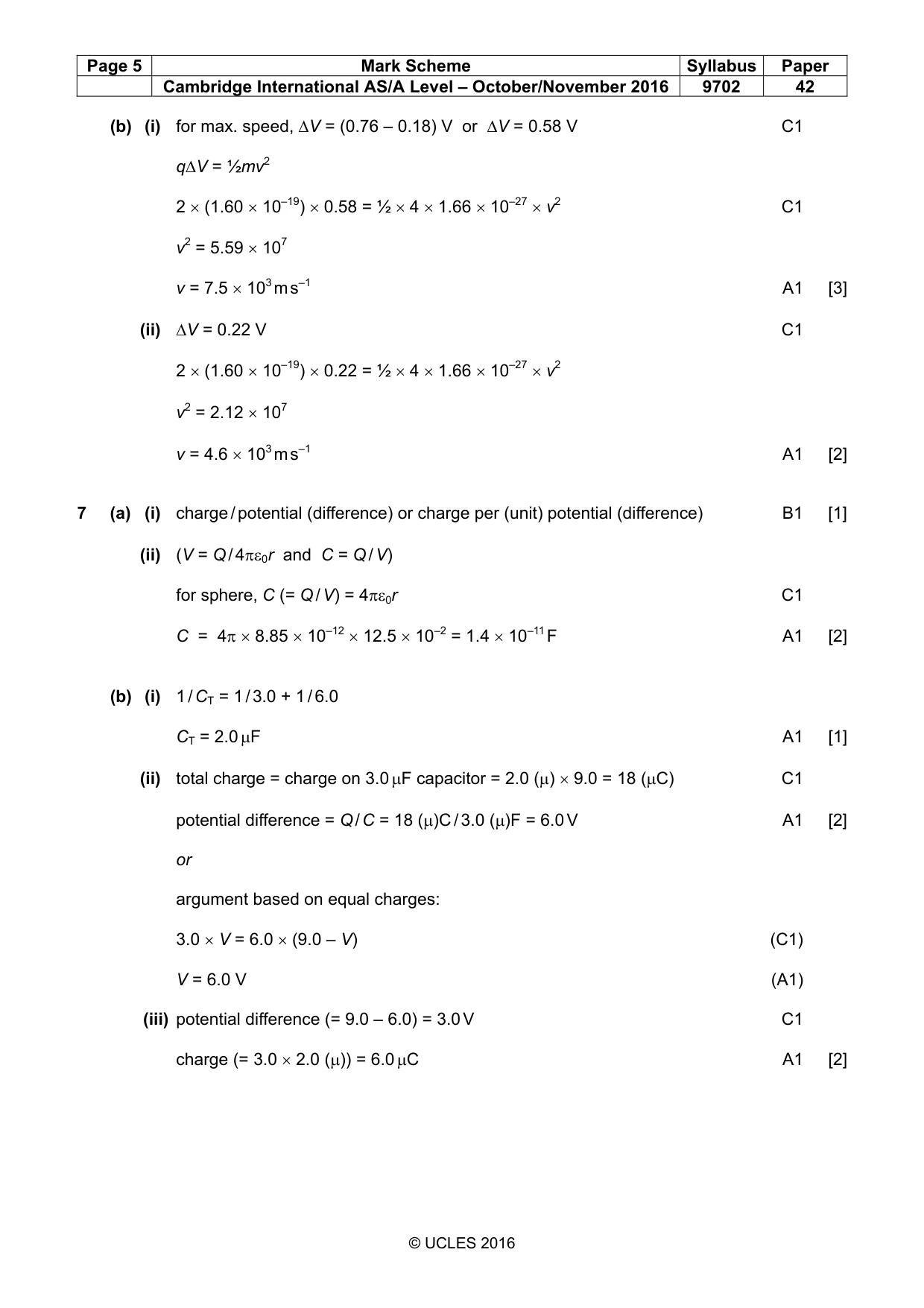
Mark scheme: 6 (a) E = 0 or EA = (–)EB (at x = 11 cm) B1 QA / x2 = QB / (20 – x)2 = 112 / 92 C1 QA / QB or ratio = 1.5 A1 [3] or E ∝ Q because r same or E = Q / 4πε0r2 and r same (B1) QA / QB = 48 / 32 (C1) QA / QB or ratio = 1.5 (A1) (b) (i) for max. speed, ∆V = (0.76 – 0.18) V or ∆V = 0.58 V C1 q∆V = ½mv2 2 × (1.60 × 10–19) × 0.58 = ½ × 4 × 1.66 × 10–27 × v2 C1 v2 = 5.59 × 10⁷ v = 7.5 × 10³ m s–1 A1 [3] (ii) ∆V = 0.22 V C1 2 × (1.60 × 10–19) × 0.22 = ½ × 4 × 1.66 × 10–27 × v2 v2 = 2.12 × 10⁷ v = 4.6 × 10³ m s–1 A1 [2]
Question 7
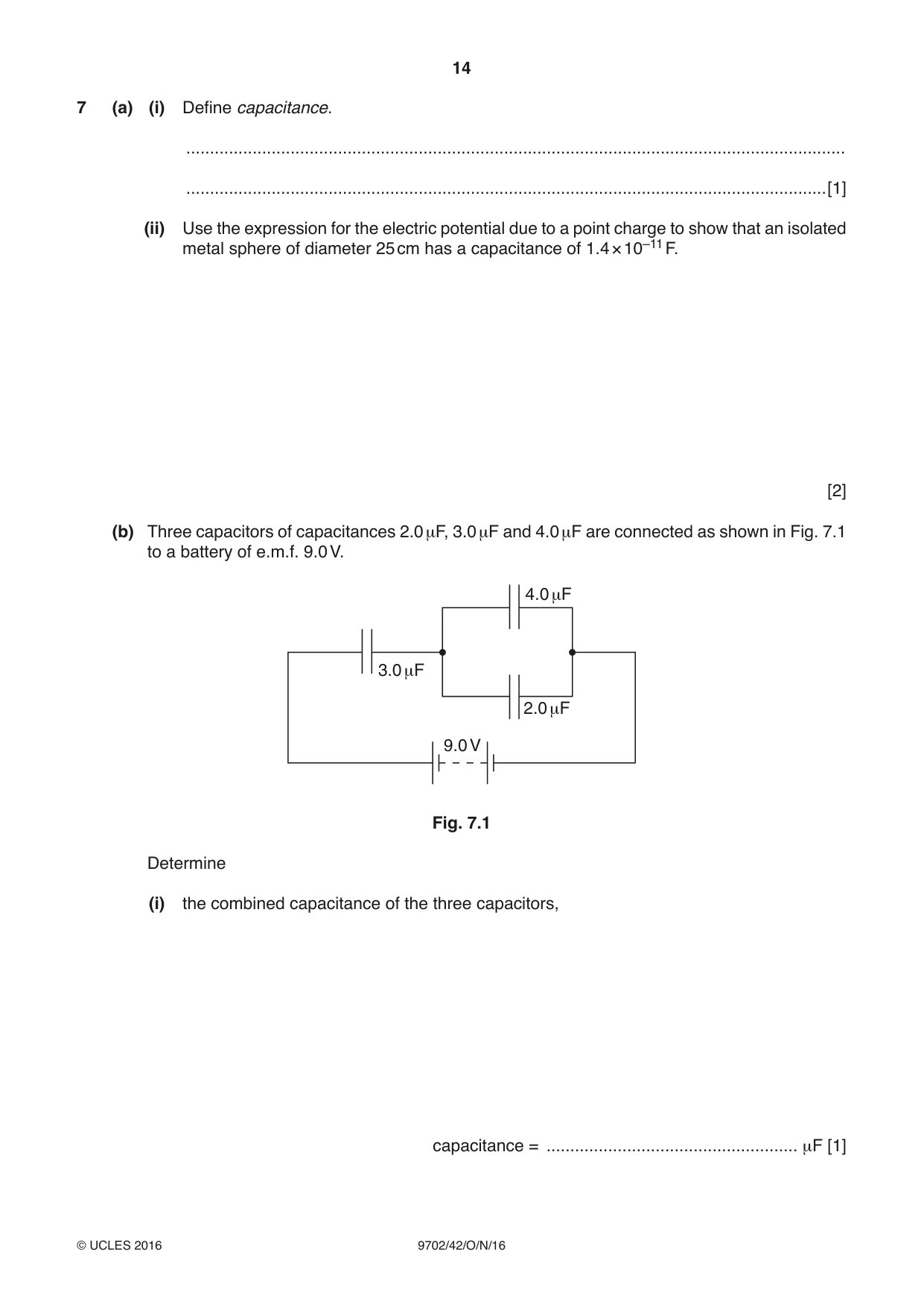
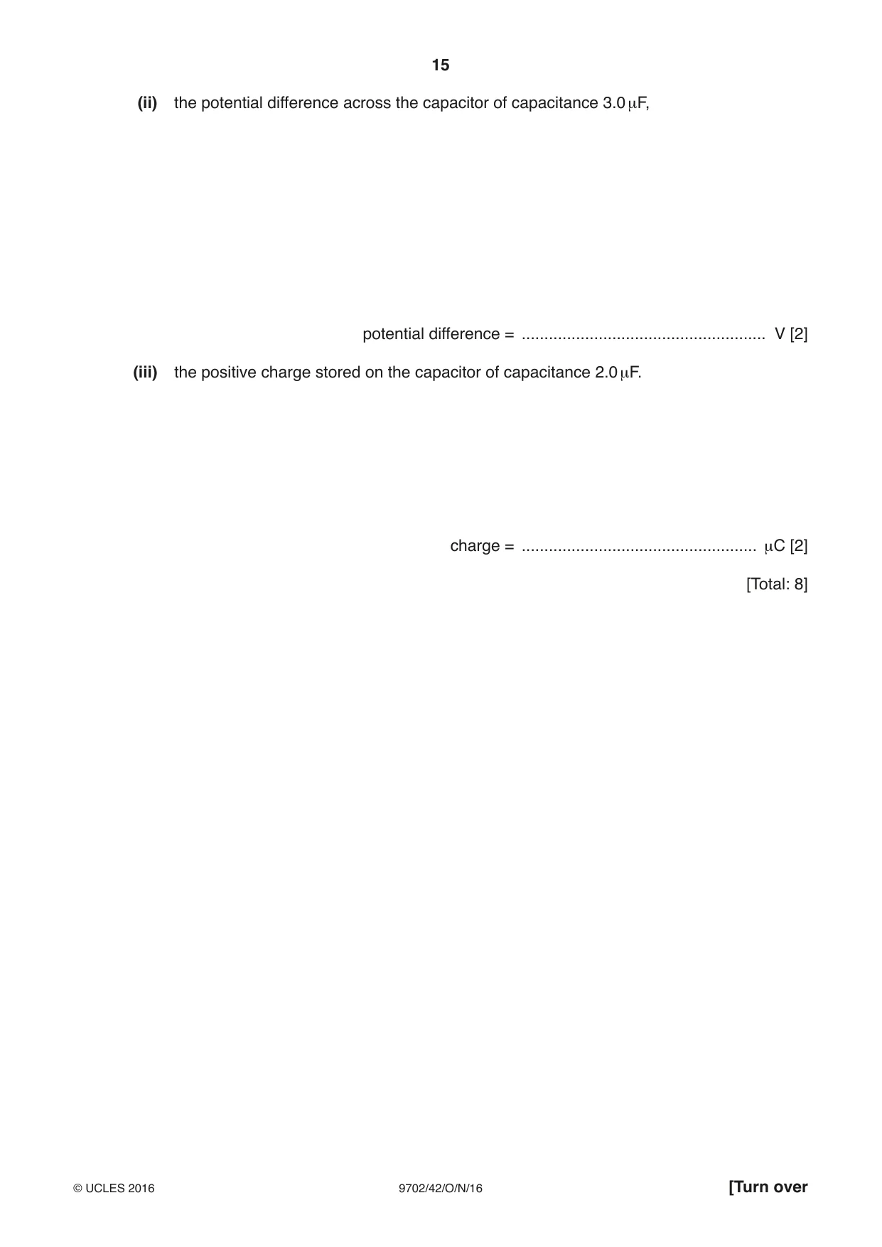
7 (a) (i) Define capacitance. ........................................................................................................................................... .......................................................................................................................................[1] (ii) Use the expression for the electric potential due to a point charge to show that an isolated metal sphere of diameter 25 cm has a capacitance of 1.4 × 10⁻¹¹ F. [2] (b) Three capacitors of capacitances 2.0 μF, 3.0 μF and 4.0 μF are connected as shown in Fig. 7.1 to a battery of e.m.f. 9.0 V. 4.0 μF 3.0 μF 2.0 μF 9.0 V Fig. 7.1 Determine (i) the combined capacitance of the three capacitors, capacitance = ..................................................... μF [1] (ii) the potential difference across the capacitor of capacitance 3.0 μF, potential difference = ...................................................... V [2] (iii) the positive charge stored on the capacitor of capacitance 2.0 μF. charge = .................................................... μC [2] [Total: 8]
Mark scheme: 7 (a) (i) charge / potential (difference) or charge per (unit) potential (difference) B1 [1] (ii) (V = Q / 4πε0r and C = Q / V) for sphere, C (= Q / V) = 4πε0r C1 C = 4π × 8.85 × 10–12 × 12.5 × 10–2 = 1.4 × 10⁻¹¹ F A1 [2] (b) (i) 1 / CT = 1 / 3.0 + 1 / 6.0 CT = 2.0 µF A1 [1] (ii) total charge = charge on 3.0 µF capacitor = 2.0 (µ) × 9.0 = 18 (µC) C1 potential difference = Q / C = 18 (µ)C / 3.0 (µ)F = 6.0 V A1 [2] or argument based on equal charges: 3.0 × V = 6.0 × (9.0 – V) (C1) V = 6.0 V (A1) (iii) potential difference (= 9.0 – 6.0) = 3.0 V C1 charge (= 3.0 × 2.0 (µ)) = 6.0 µC A1 [2]
Q8 · A circuit incorporating an ideal operational amplifier (op-amp) is shown in Fig
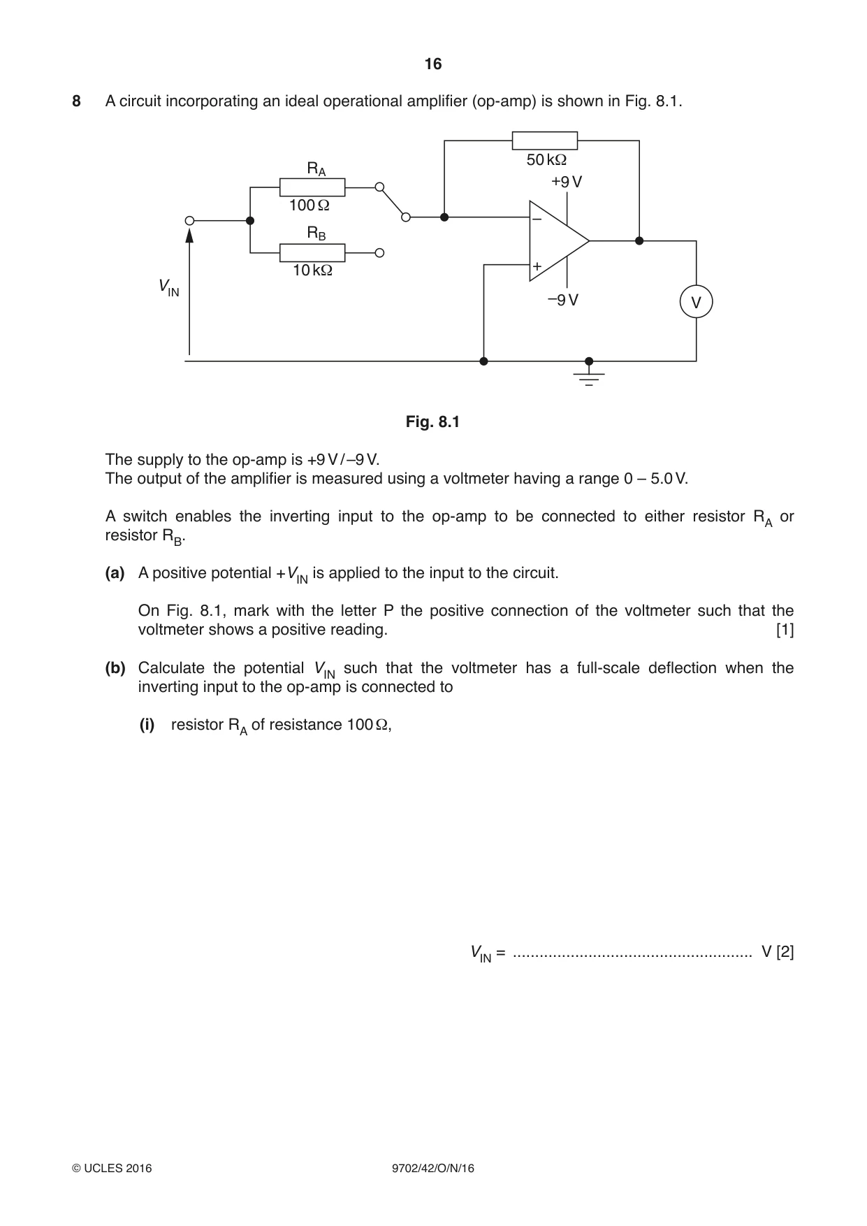
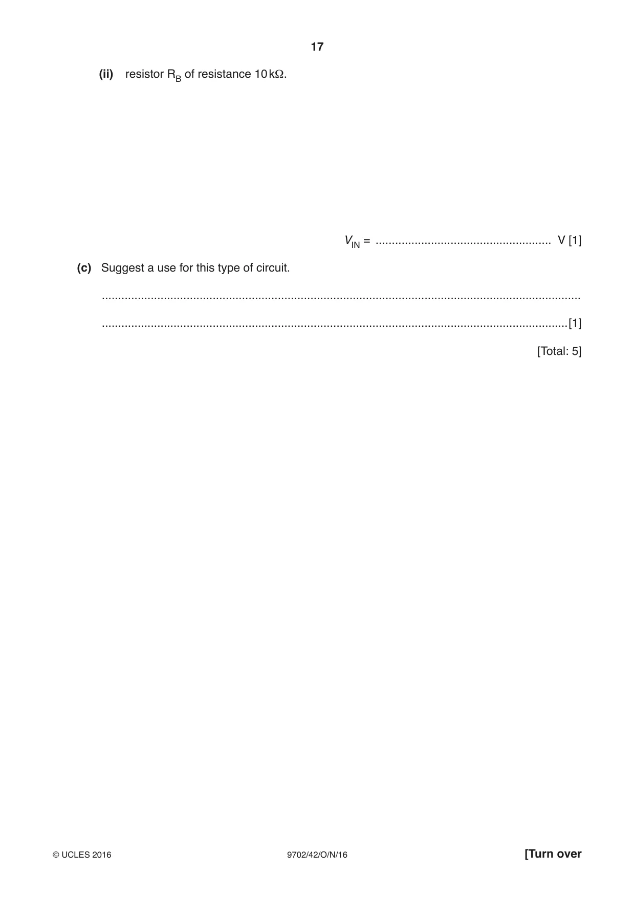
8 A circuit incorporating an ideal operational amplifier (op-amp) is shown in Fig. 8.1. 50 kΩ RA +9 V 100 Ω – RB + 10 kΩ VIN –9 V V Fig. 8.1 The supply to the op-amp is +9 V / –9 V. The output of the amplifier is measured using a voltmeter having a range 0 – 5.0 V. A switch enables the inverting input to the op-amp to be connected to either resistor RA or resistor RB. (a) A positive potential +VIN is applied to the input to the circuit. On Fig. 8.1, mark with the letter P the positive connection of the voltmeter such that the voltmeter shows a positive reading. [1] (b) Calculate the potential VIN such that the voltmeter has a full-scale deflection when the inverting input to the op-amp is connected to (i) resistor RA of resistance 100 Ω, VIN = ...................................................... V [2] (ii) resistor RB of resistance 10 kΩ. VIN = ...................................................... V [1] (c) Suggest a use for this type of circuit. ................................................................................................................................................... ...............................................................................................................................................[1] [Total: 5]
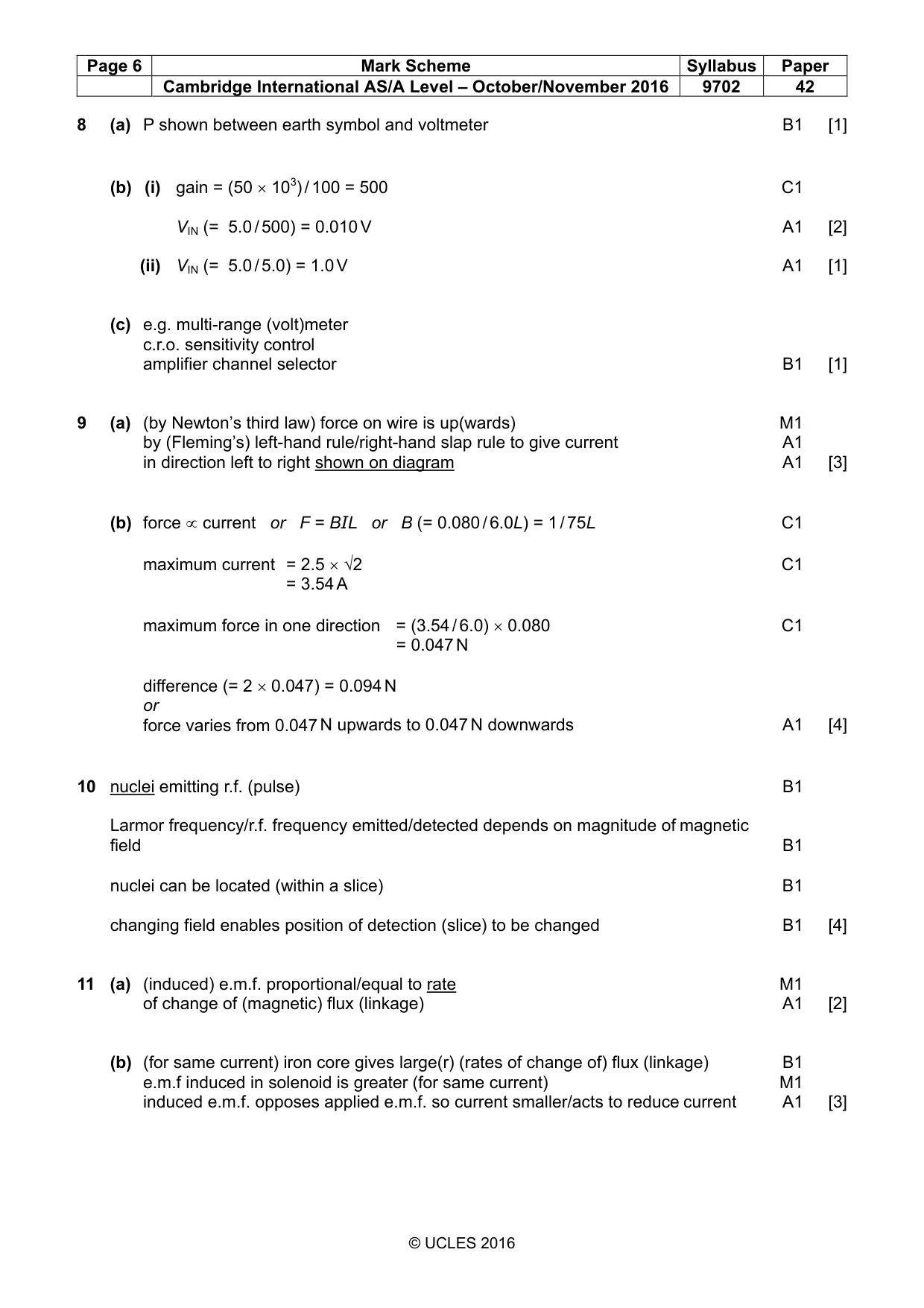
Mark scheme: 8 (a) P shown between earth symbol and voltmeter B1 [1] (b) (i) gain = (50 × 103) / 100 = 500 C1 VIN (= 5.0 / 500) = 0.010 V A1 [2] (ii) VIN (= 5.0 / 5.0) = 1.0 V A1 [1] (c) e.g. multi-range (volt)meter c.r.o. sensitivity control amplifier channel selector B1 [1]
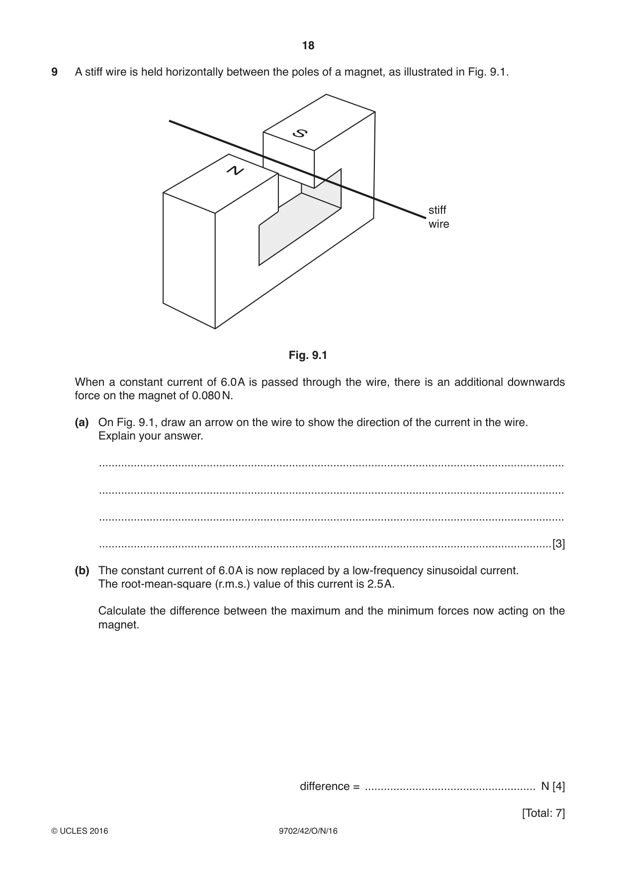
Q9 · A stiff wire is held horizontally between the poles of a magnet, as illustrated in Fig
9 A stiff wire is held horizontally between the poles of a magnet, as illustrated in Fig. 9.1. S N stiff wire Fig. 9.1 When a constant current of 6.0 A is passed through the wire, there is an additional downwards force on the magnet of 0.080 N. (a) On Fig. 9.1, draw an arrow on the wire to show the direction of the current in the wire. Explain your answer. ................................................................................................................................................... ................................................................................................................................................... ................................................................................................................................................... ...............................................................................................................................................[3] (b) The constant current of 6.0 A is now replaced by a low-frequency sinusoidal current. The root-mean-square (r.m.s.) value of this current is 2.5 A. Calculate the difference between the maximum and the minimum forces now acting on the magnet. difference = ...................................................... N [4] [Total: 7]
Mark scheme: 9 (a) (by Newton’s third law) force on wire is up(wards) M1 by (Fleming’s) left-hand rule/right-hand slap rule to give current A1 in direction left to right shown on diagram A1 [3] (b) force ∝ current or F = BIL or B (= 0.080 / 6.0L) = 1 / 75L C1 maximum current = 2.5 × √2 C1 = 3.54 A maximum force in one direction = (3.54 / 6.0) × 0.080 C1 = 0.047 N difference (= 2 × 0.047) = 0.094 N or force varies from 0.047 N upwards to 0.047 N downwards A1 [4]
Q10 · Explain the function of the non-uniform magnetic field that is superimposed on a large…
10 Explain the function of the non-uniform magnetic field that is superimposed on a large uniform magnetic field in diagnosis using nuclear magnetic resonance imaging (NMRI). .......................................................................................................................................................... .......................................................................................................................................................... .......................................................................................................................................................... .......................................................................................................................................................... .......................................................................................................................................................... .......................................................................................................................................................... .......................................................................................................................................................... ......................................................................................................................................................[4] [Total: 4]
Mark scheme: 10 nuclei emitting r.f. (pulse) B1 Larmor frequency/r.f. frequency emitted/detected depends on magnitude of magnetic field B1 nuclei can be located (within a slice) B1 changing field enables position of detection (slice) to be changed B1 [4]
Q11 · State Faraday’s law of electromagnetic induction
11 (a) State Faraday’s law of electromagnetic induction. ................................................................................................................................................... ................................................................................................................................................... ...............................................................................................................................................[2] (b) An alternating current is passed through an air-cored solenoid. An iron core is inserted into the solenoid and then held stationary within the solenoid. The current in the solenoid is now smaller. Explain why the root-mean-square (r.m.s.) value of the current in the solenoid is reduced as a result of inserting the core. ................................................................................................................................................... ................................................................................................................................................... ................................................................................................................................................... ................................................................................................................................................... ...............................................................................................................................................[3] (c) Practical transformers are very efficient. However, there are some power losses. State two sources of power loss within a transformer. 1. ............................................................................................................................................... ................................................................................................................................................... 2. ............................................................................................................................................... ................................................................................................................................................... [2] [Total: 7]
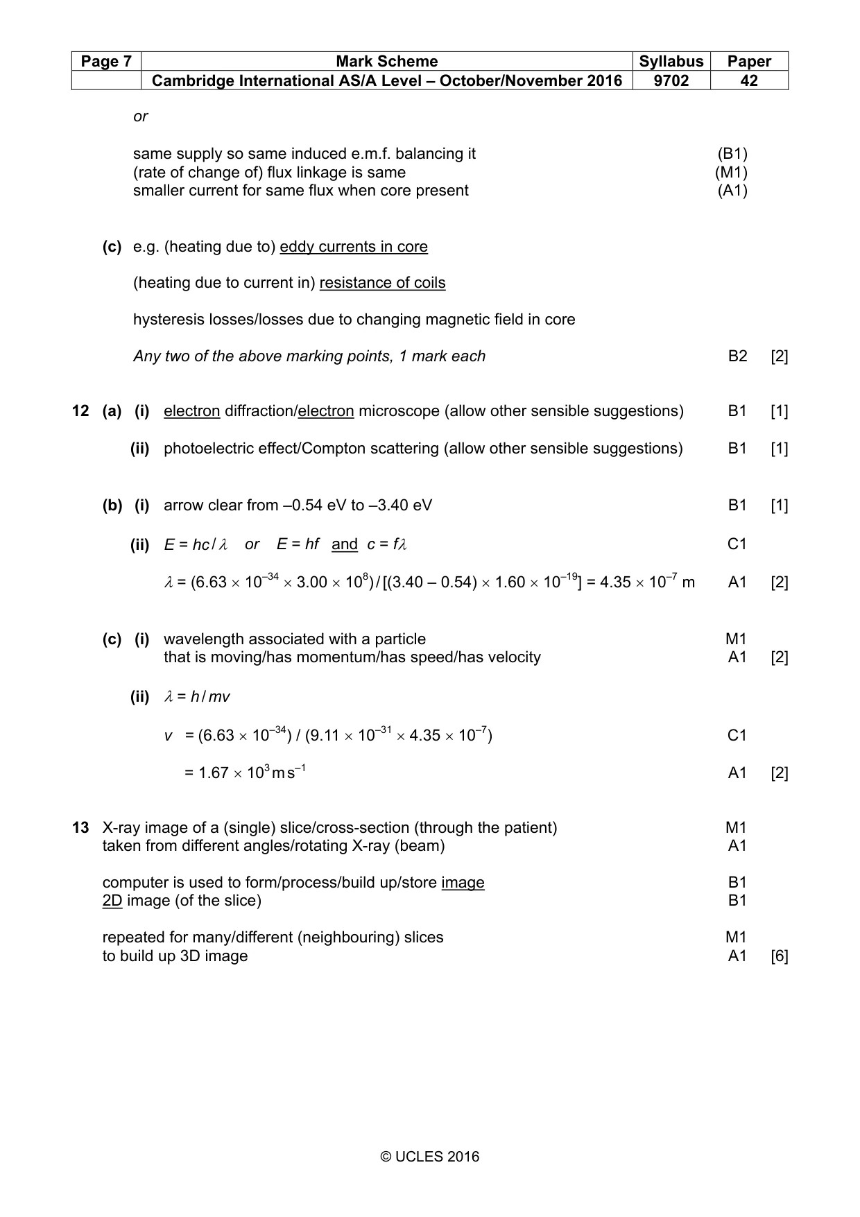
Mark scheme: 11 (a) (induced) e.m.f. proportional/equal to rate M1 of change of (magnetic) flux (linkage) A1 [2] (b) (for same current) iron core gives large(r) (rates of change of) flux (linkage) B1 e.m.f induced in solenoid is greater (for same current) M1 induced e.m.f. opposes applied e.m.f. so current smaller/acts to reduce current A1 [3] or same supply so same induced e.m.f. balancing it (B1) (rate of change of) flux linkage is same (M1) smaller current for same flux when core present (A1) (c) e.g. (heating due to) eddy currents in core (heating due to current in) resistance of coils hysteresis losses/losses due to changing magnetic field in core Any two of the above marking points, 1 mark each B2 [2]
Q12 · State an effect, one in each case, that provides evidence for (i) the wave nature of a…
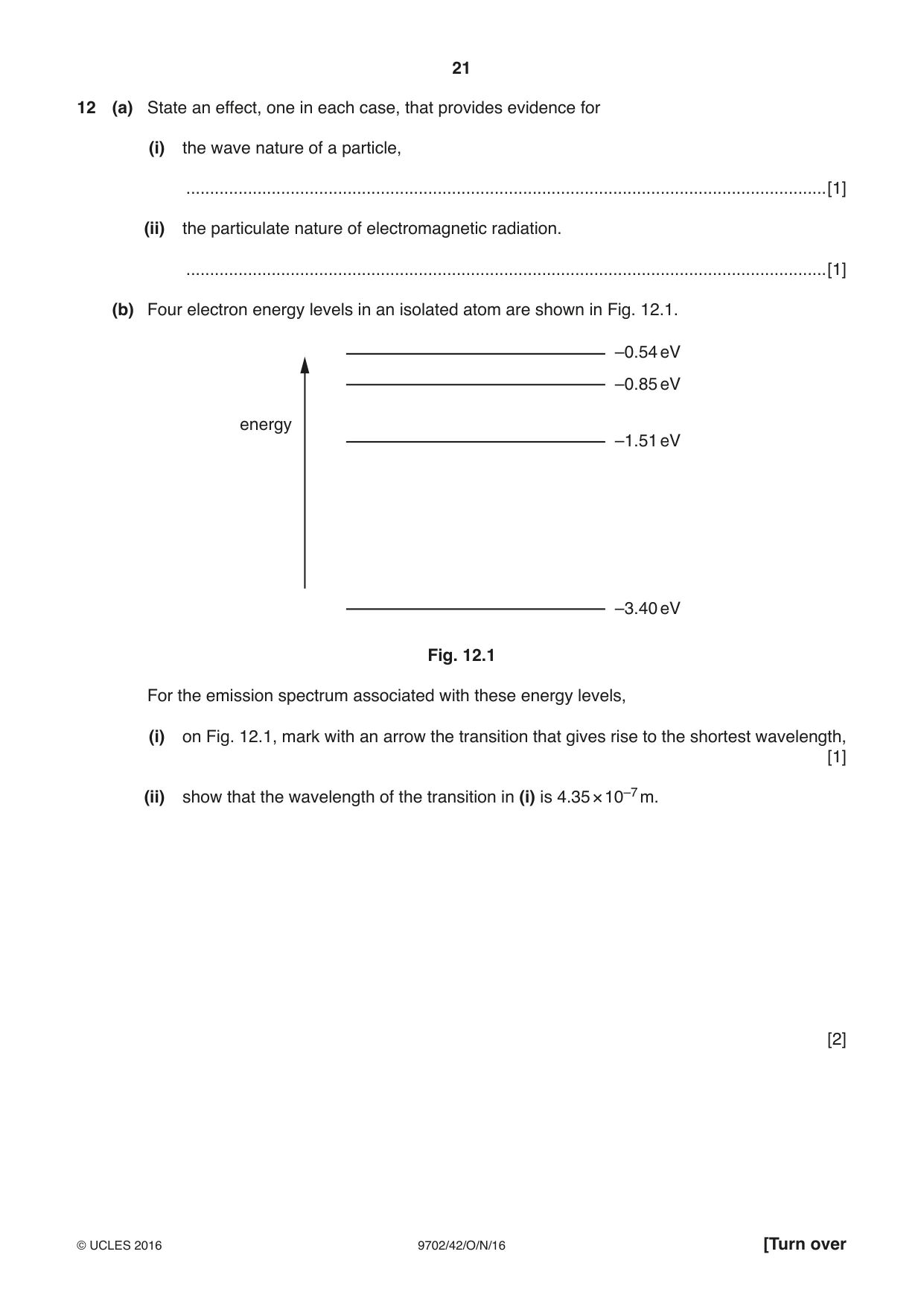
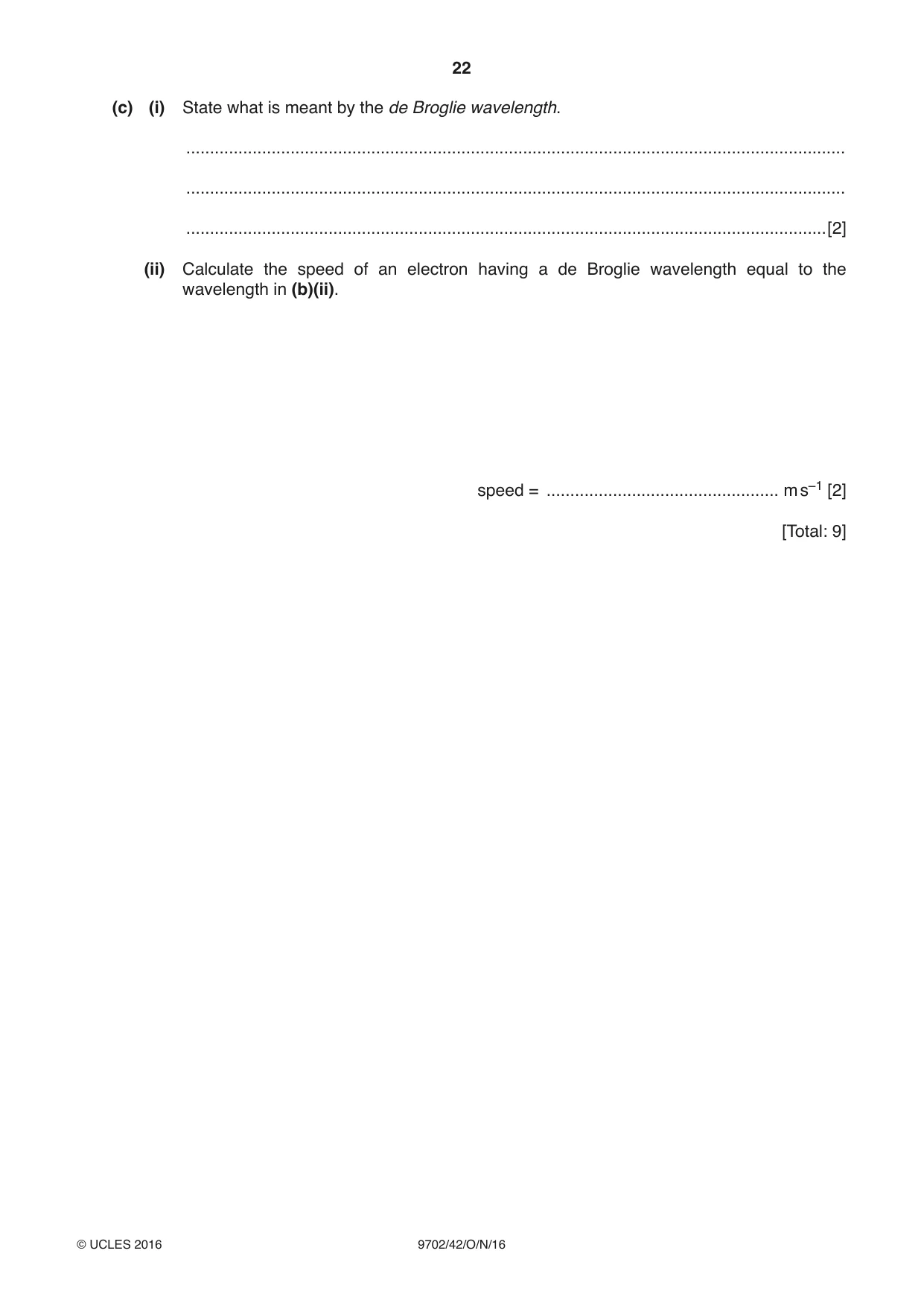
12 (a) State an effect, one in each case, that provides evidence for (i) the wave nature of a particle, .......................................................................................................................................[1] (ii) the particulate nature of electromagnetic radiation. .......................................................................................................................................[1] (b) Four electron energy levels in an isolated atom are shown in Fig. 12.1. –0.54 eV –0.85 eV energy –1.51 eV –3.40 eV Fig. 12.1 For the emission spectrum associated with these energy levels, (i) on Fig. 12.1, mark with an arrow the transition that gives rise to the shortest wavelength, [1] (ii) show that the wavelength of the transition in (i) is 4.35 × 10⁻⁷ m. [2] (c) (i) State what is meant by the de Broglie wavelength. ........................................................................................................................................... ........................................................................................................................................... .......................................................................................................................................[2] (ii) Calculate the speed of an electron having a de Broglie wavelength equal to the wavelength in (b)(ii). speed = ................................................. m s–1 [2] [Total: 9]
Mark scheme: 12 (a) (i) electron diffraction/electron microscope (allow other sensible suggestions) B1 [1] (ii) photoelectric effect/Compton scattering (allow other sensible suggestions) B1 [1] (b) (i) arrow clear from –0.54 eV to –3.40 eV B1 [1] (ii) E = hc / λ or E = hf and c = fλ C1 λ= (6.63 × 10–34 × 3.00 × 108) / [(3.40 – 0.54) × 1.60 × 10–19] = 4.35 × 10⁻⁷ m A1 [2] (c) (i) wavelength associated with a particle M1 that is moving/has momentum/has speed/has velocity A1 [2] (ii) λ= h / mv v = (6.63 × 10⁻³⁴) / (9.11 × 10–31 × 4.35 × 10–7) C1 = 1.67 × 10³ m s–1 A1 [2]
Q13 · Outline the principles of computed tomography (CT scanning)
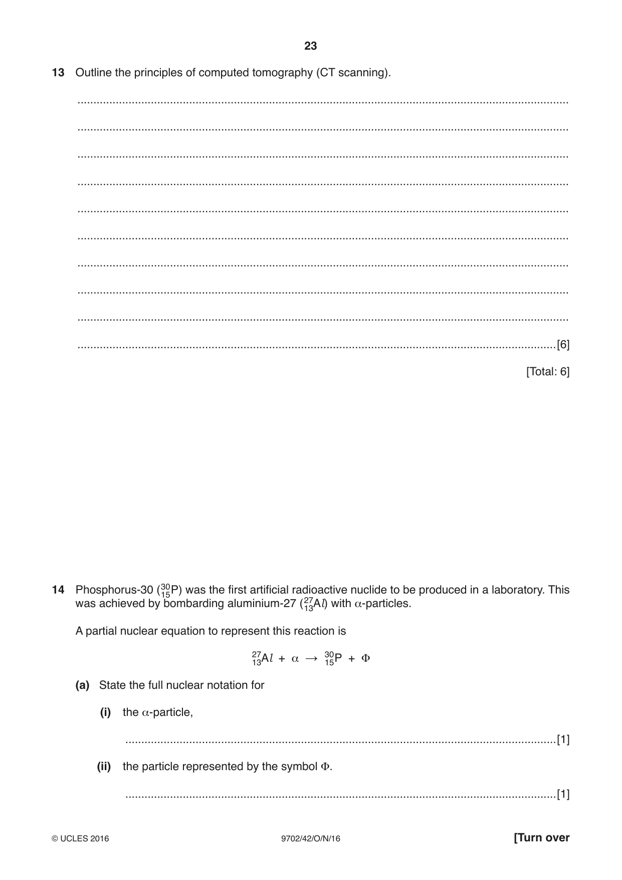
13 Outline the principles of computed tomography (CT scanning). .......................................................................................................................................................... .......................................................................................................................................................... .......................................................................................................................................................... .......................................................................................................................................................... .......................................................................................................................................................... .......................................................................................................................................................... .......................................................................................................................................................... .......................................................................................................................................................... .......................................................................................................................................................... ......................................................................................................................................................[6] [Total: 6]
Mark scheme: 13 X-ray image of a (single) slice/cross-section (through the patient) M1 taken from different angles/rotating X-ray (beam) A1 computer is used to form/process/build up/store image B1 2D image (of the slice) B1 repeated for many/different (neighbouring) slices M1 to build up 3D image A1 [6] 4 4
Q14 · Phosphorus-30 (3015P) was the first artificial radioactive nuclide to be produced in a…
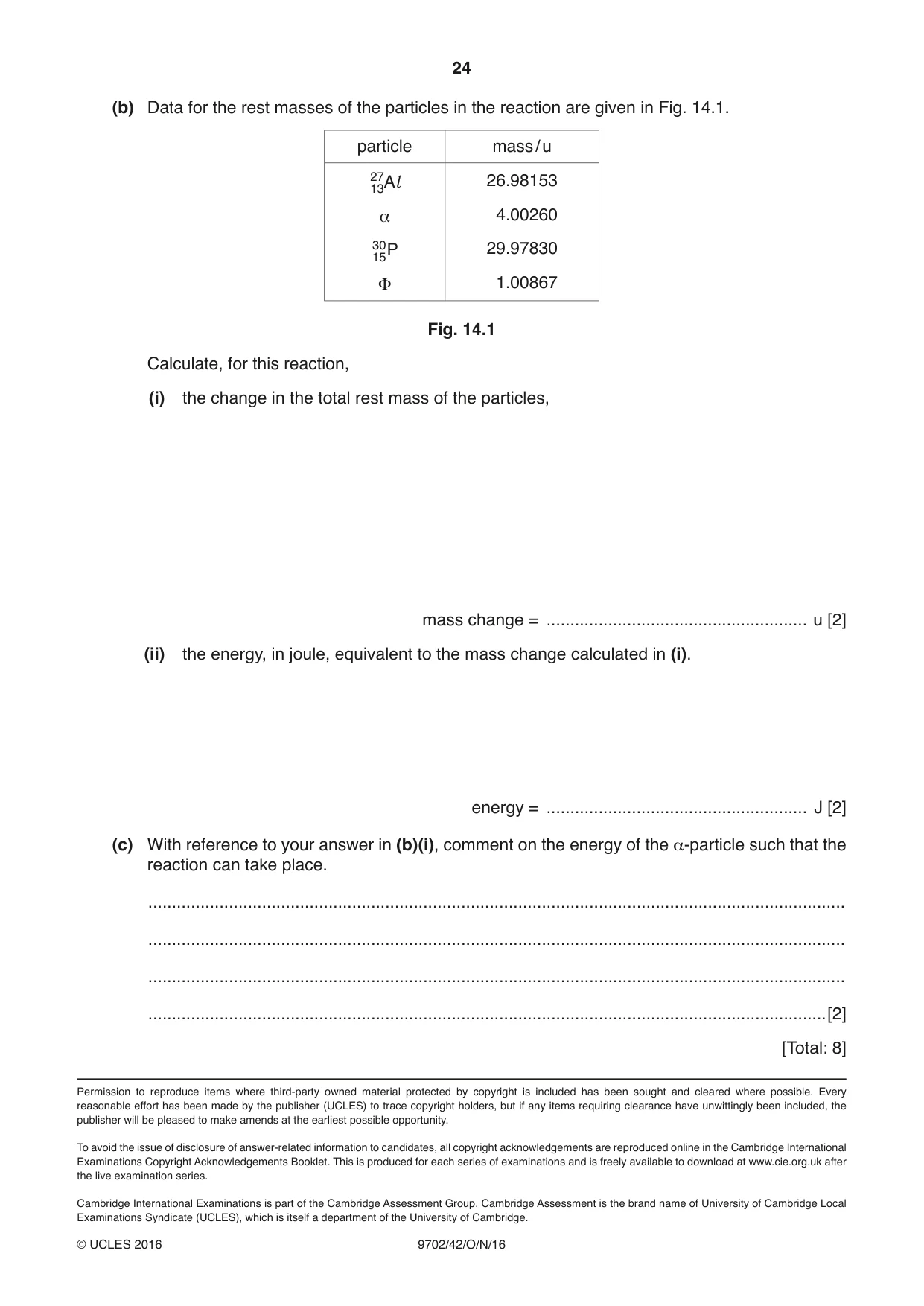
14 Phosphorus-30 (3015P) was the first artificial radioactive nuclide to be produced in a laboratory. This was achieved by bombarding aluminium-27 (2713Al) with α-particles. A partial nuclear equation to represent this reaction is Φ 2713Al + 30 α → 15P + (a) State the full nuclear notation for (i) the α-particle, .......................................................................................................................................[1] (ii) the particle represented by the symbol Φ. .......................................................................................................................................[1] (b) Data for the rest masses of the particles in the reaction are given in Fig. 14.1. particle mass / u 2713Al 26.98153 α 4.00260 3015P 29.97830 Φ 1.00867 Fig. 14.1 Calculate, for this reaction, (i) the change in the total rest mass of the particles, mass change = ....................................................... u [2] (ii) the energy, in joule, equivalent to the mass change calculated in (i). energy = ....................................................... J [2] (c) With reference to your answer in (b)(i), comment on the energy of the α-particle such that the reaction can take place. ................................................................................................................................................... ................................................................................................................................................... ................................................................................................................................................... ...............................................................................................................................................[2] [Total: 8]
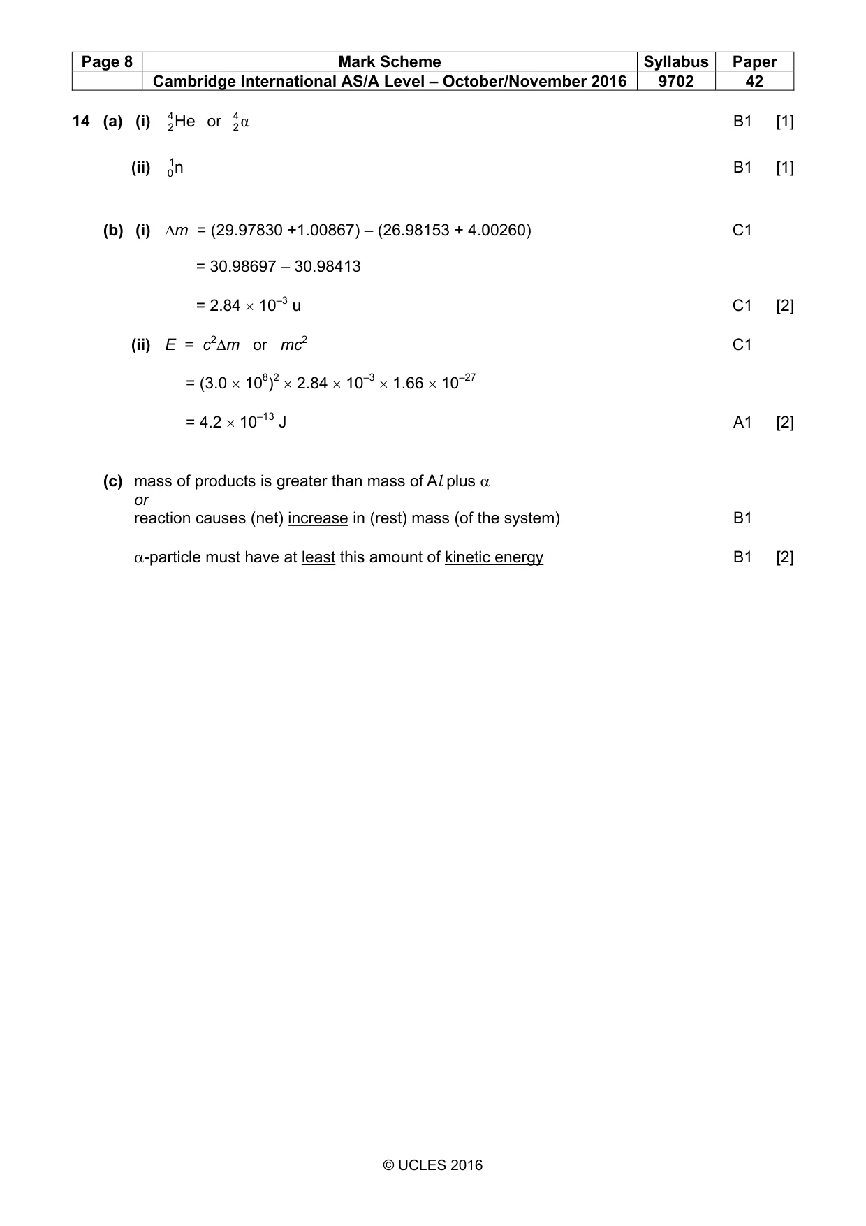
Mark scheme: 14 (a) (i) 42 He or 42 α B1 [1] (ii) 01n B1 [1] (b) (i) ∆m = (29.97830 +1.00867) – (26.98153 + 4.00260) C1 = 30.98697 – 30.98413 = 2.84 × 10⁻³ u C1 [2] (ii) E = c2∆m or mc2 C1 = (3.0 × 10⁸)2 × 2.84 × 10–3 × 1.66 × 10–27 = 4.2 × 10⁻¹³ J A1 [2] (c) mass of products is greater than mass of Al plus α or reaction causes (net) increase in (rest) mass (of the system) B1 α-particle must have at least this amount of kinetic energy B1 [2]
What was in this paper
The subtopics covered by these 14 questions, and how many questions each got. Open one in a new tab to see every Cambridge question on it.
2Atoms, nuclei and radiation1Capacitors and capacitance1Concept of a magnetic field1Electric potential1Electromagnetic induction1Energy levels in atoms and line spectra1Force on a current-carrying conductor1Gravitational field of a point mass1Practical circuits1Simple harmonic oscillations1Temperature scales1The first law of thermodynamics1What you needed in this session
Cambridge’s own grade thresholds for 2016 Oct/Nov, Paper 4 · Variant 2. A higher threshold means an easier paper — the bar moves with how the cohort did.