Cambridge A Level Physics 9702 — 2011 Oct/Nov Paper 4 · Variant 2
9702/42/O/N/11 · 11 questions · 100 marks · ≈113 min
The question paper and its mark scheme, free to read here and free to download. This is Cambridge’s own paper, exactly as it was sat.
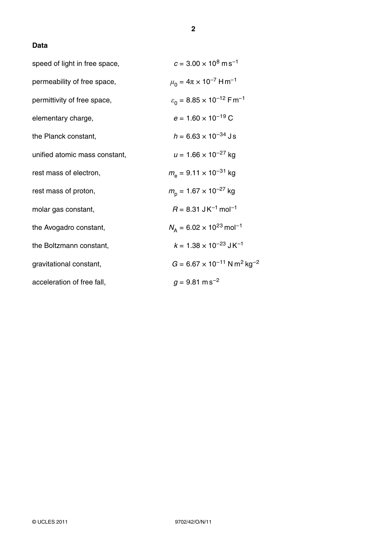
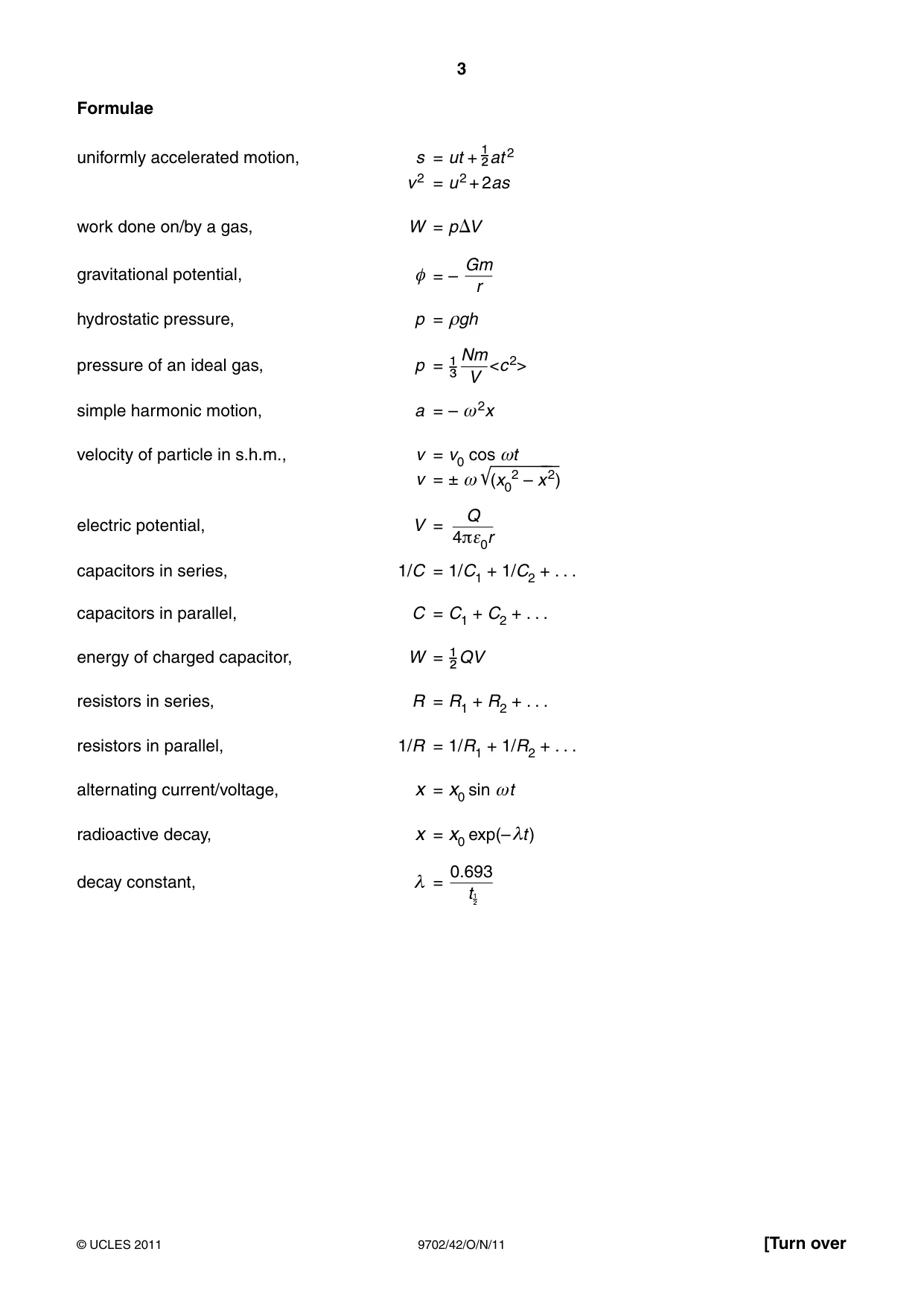
Question paper24 pages
Mark scheme6 pages
Answers below. Sit the paper first if you are practising.
Questions as text
Q1 · A moon is in a circular orbit of radius r about a planet
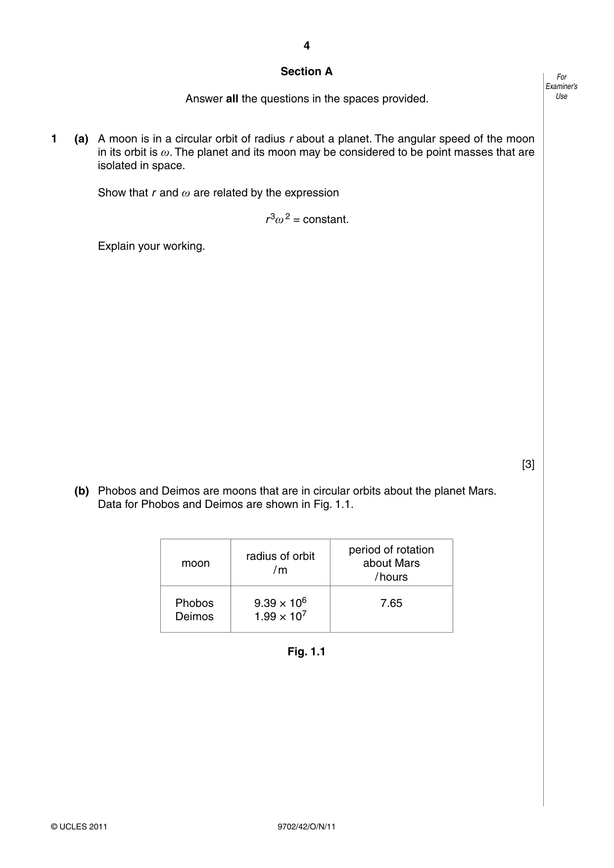
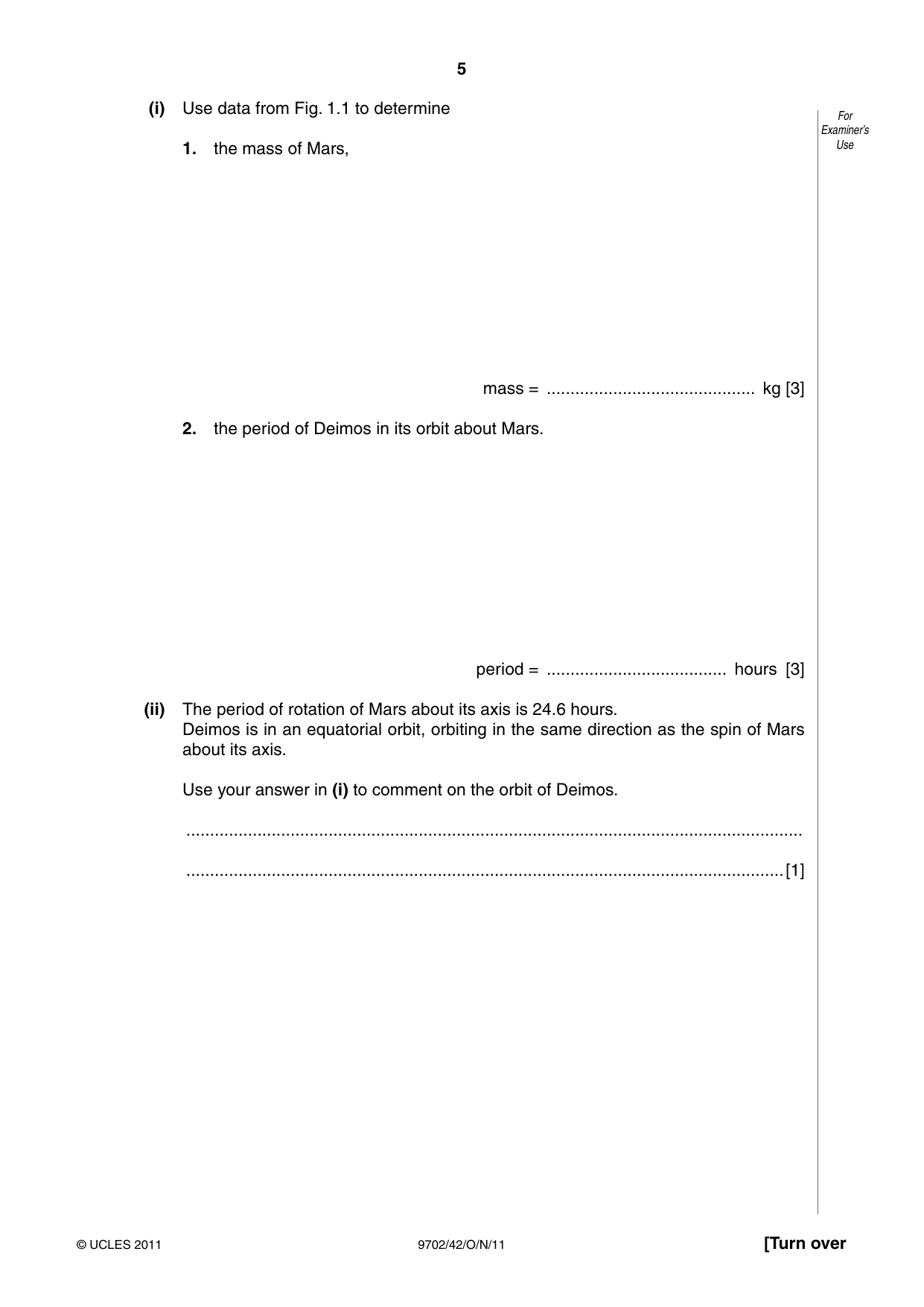
1 (a) A moon is in a circular orbit of radius r about a planet. The angular speed of the moon in its orbit is ω. The planet and its moon may be considered to be point masses that are isolated in space. Show that r and ω are related by the expression r 3ω 2 = constant. Explain your working. [3] (b) Phobos and Deimos are moons that are in circular orbits about the planet Mars. Data for Phobos and Deimos are shown in Fig. 1.1. period of rotation radius of orbit moon about Mars / m / hours Phobos 9.39 × 10⁶ 7.65 Deimos 1.99 × 10⁷ Fig. 1.1 (i) Use data from Fig. 1.1 to determine For Examiner’s 1. the mass of Mars, Use mass = ............................................ kg [3] 2. the period of Deimos in its orbit about Mars. period = ...................................... hours [3] (ii) The period of rotation of Mars about its axis is 24.6 hours. Deimos is in an equatorial orbit, orbiting in the same direction as the spin of Mars about its axis. Use your answer in (i) to comment on the orbit of Deimos. .................................................................................................................................. ..............................................................................................................................[1]
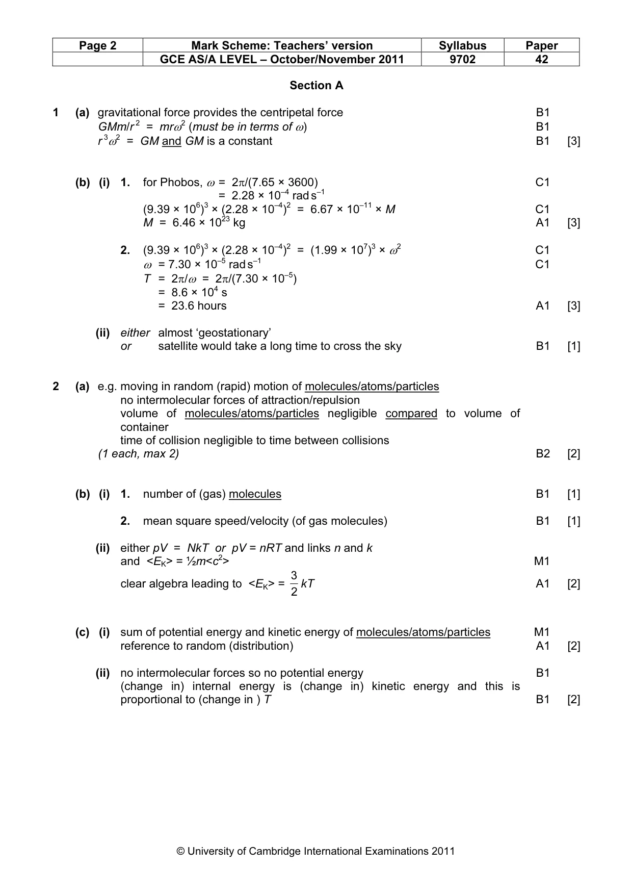
Mark scheme: 1 (a) gravitational force provides the centripetal force B1 GMm/r 2 = mrω2 (must be in terms of ω) B1 r 3ω2 = GM and GM is a constant B1 [3] (b) (i) 1. for Phobos, ω = 2π/(7.65 × 3600) C1 = 2.28 × 10⁻⁴ rad s–1 (9.39 × 10⁶)3 × (2.28 × 10–4)2 = 6.67 × 10⁻¹¹ × M C1 M = 6.46 × 10²³ kg A1 [3] 2. (9.39 × 10⁶)3 × (2.28 × 10–4)2 = (1.99 × 10⁷)3 × ω2 C1 ω = 7.30 × 10⁻⁵ rad s–1 C1 T = 2π/ω = 2π/(7.30 × 10–5) = 8.6 × 10⁴ s = 23.6 hours A1 [3] (ii) either almost ‘geostationary’ or satellite would take a long time to cross the sky B1 [1]
Q2 · One assumption of the kinetic theory of gases is that gas molecules behave as if they For…
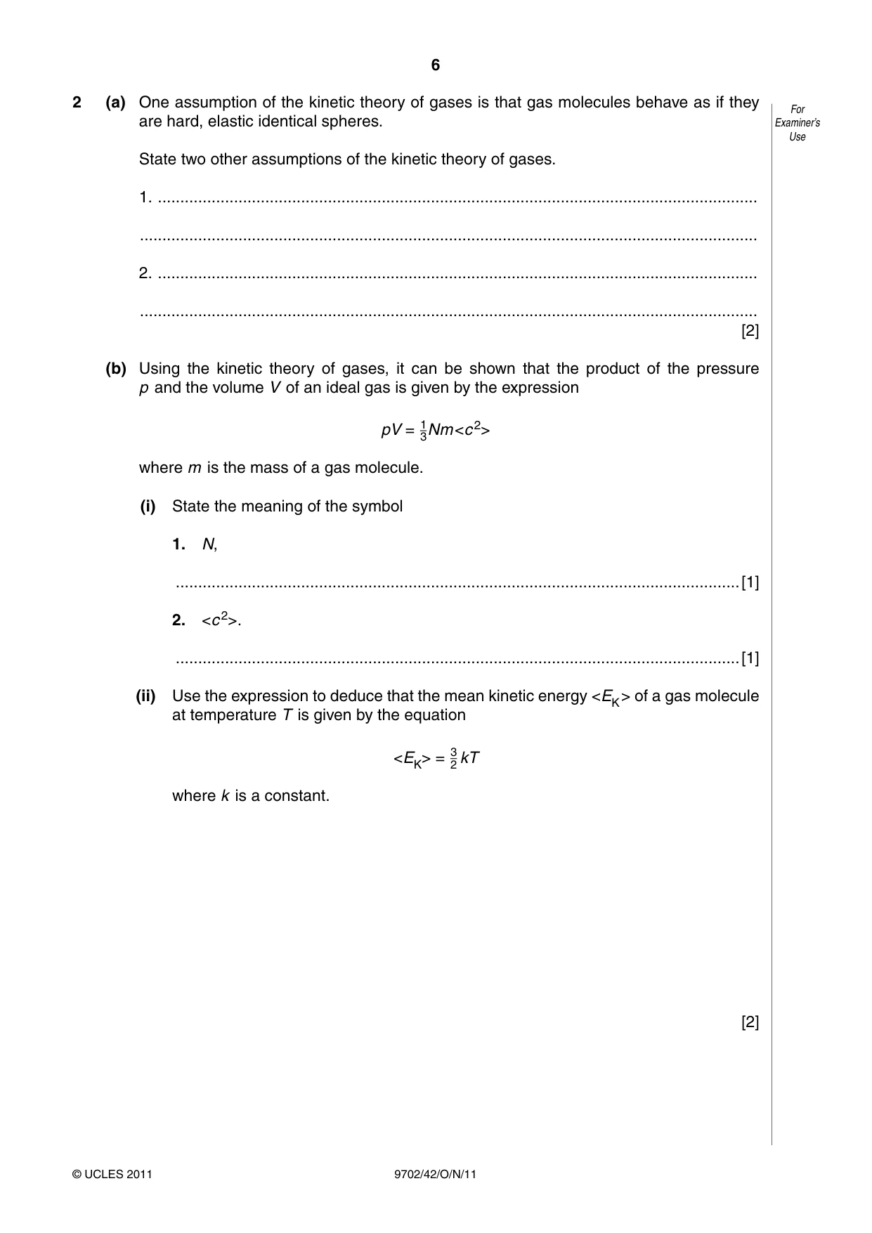
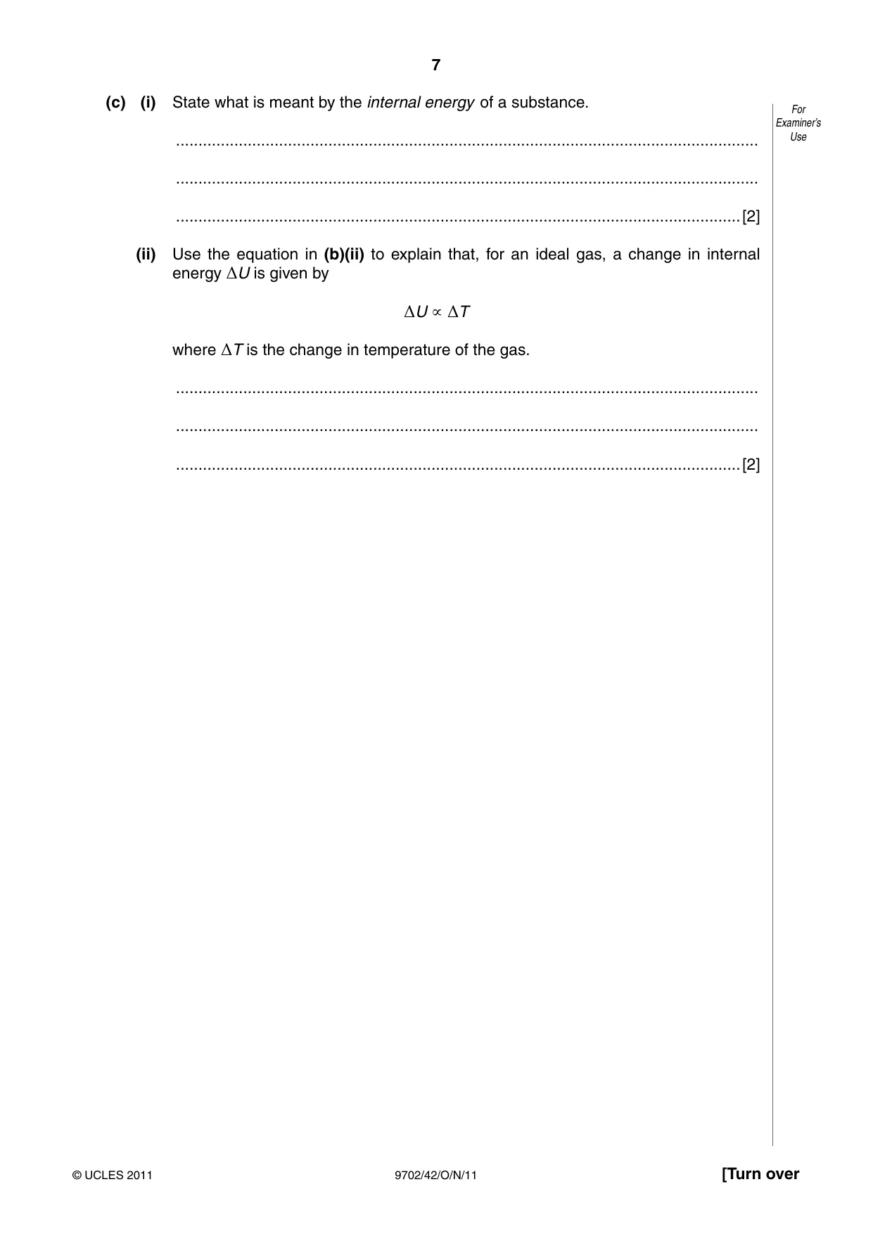
2 (a) One assumption of the kinetic theory of gases is that gas molecules behave as if they For are hard, elastic identical spheres. Examiner’s Use State two other assumptions of the kinetic theory of gases. 1. ...................................................................................................................................... .......................................................................................................................................... 2. ...................................................................................................................................... .......................................................................................................................................... [2] (b) Using the kinetic theory of gases, it can be shown that the product of the pressure p and the volume V of an ideal gas is given by the expression pV = 13Nm <c 2> where m is the mass of a gas molecule. (i) State the meaning of the symbol 1. N, ..............................................................................................................................[1] 2. <c 2>. ..............................................................................................................................[1] (ii) Use the expression to deduce that the mean kinetic energy <EK > of a gas molecule at temperature T is given by the equation <EK> = 32 kT where k is a constant. [2] (c) (i) State what is meant by the internal energy of a substance. For Examiner’s .................................................................................................................................. Use .................................................................................................................................. ..............................................................................................................................[2] (ii) Use the equation in (b)(ii) to explain that, for an ideal gas, a change in internal energy ΔU is given by ΔU ∝ ΔT where ΔT is the change in temperature of the gas. .................................................................................................................................. .................................................................................................................................. ..............................................................................................................................[2]
Mark scheme: 2 (a) e.g. moving in random (rapid) motion of molecules/atoms/particles no intermolecular forces of attraction/repulsion volume of molecules/atoms/particles negligible compared to volume of container time of collision negligible to time between collisions (1 each, max 2) B2 [2] (b) (i) 1. number of (gas) molecules B1 [1] 2. mean square speed/velocity (of gas molecules) B1 [1] (ii) either pV = NkT or pV = nRT and links n and k and <EK> = ½m<c2> M1 3 clear algebra leading to <EK> = kT A1 [2] 2 (c) (i) sum of potential energy and kinetic energy of molecules/atoms/particles M1 reference to random (distribution) A1 [2] (ii) no intermolecular forces so no potential energy B1 (change in) internal energy is (change in) kinetic energy and this is proportional to (change in ) T B1 [2] GCE AS/A LEVEL – October/November 2011 9702 42
Q3 · A bar magnet is suspended from the free end of a helical spring, as illustrated in Fig
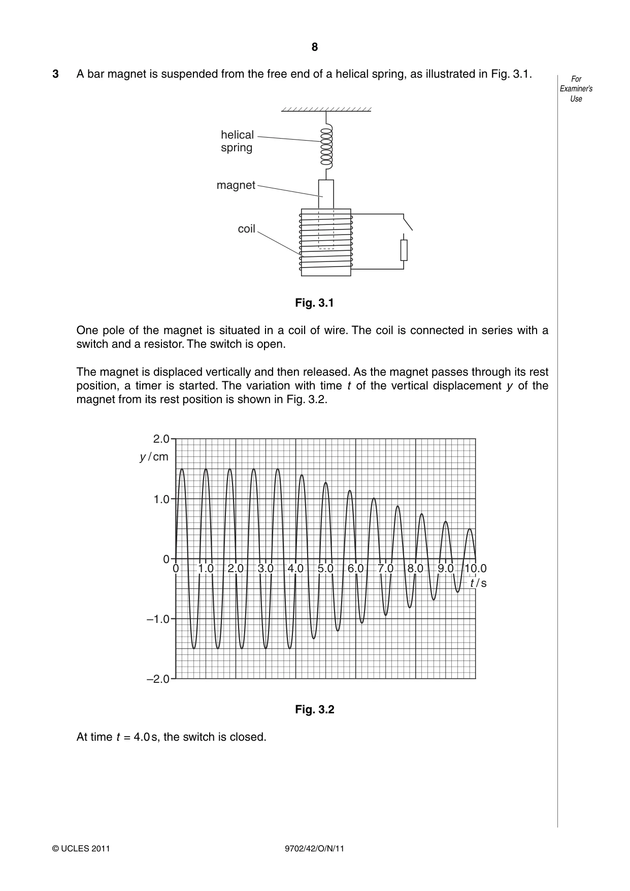
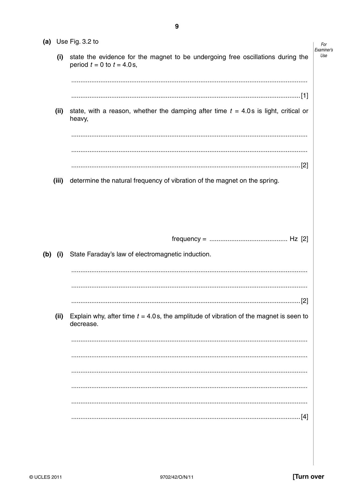
3 A bar magnet is suspended from the free end of a helical spring, as illustrated in Fig. 3.1. For Examiner’s Use helical spring magnet coil Fig. 3.1 One pole of the magnet is situated in a coil of wire. The coil is connected in series with a switch and a resistor. The switch is open. The magnet is displaced vertically and then released. As the magnet passes through its rest position, a timer is started. The variation with time t of the vertical displacement y of the magnet from its rest position is shown in Fig. 3.2. 2.0 y / cm 1.0 0 0 1.0 2.0 3.0 4.0 5.0 6.0 7.0 8.0 9.0 10.0 t / s –1.0 –2.0 Fig. 3.2 At time t = 4.0 s, the switch is closed. (a) Use Fig. 3.2 to For Examiner’s (i) state the evidence for the magnet to be undergoing free oscillations during the Use period t = 0 to t = 4.0 s, .................................................................................................................................. ..............................................................................................................................[1] (ii) state, with a reason, whether the damping after time t = 4.0 s is light, critical or heavy, .................................................................................................................................. .................................................................................................................................. ..............................................................................................................................[2] (iii) determine the natural frequency of vibration of the magnet on the spring. frequency = ........................................... Hz [2] (b) (i) State Faraday’s law of electromagnetic induction. .................................................................................................................................. .................................................................................................................................. ..............................................................................................................................[2] (ii) Explain why, after time t = 4.0 s, the amplitude of vibration of the magnet is seen to decrease. .................................................................................................................................. .................................................................................................................................. .................................................................................................................................. .................................................................................................................................. .................................................................................................................................. ..............................................................................................................................[4]
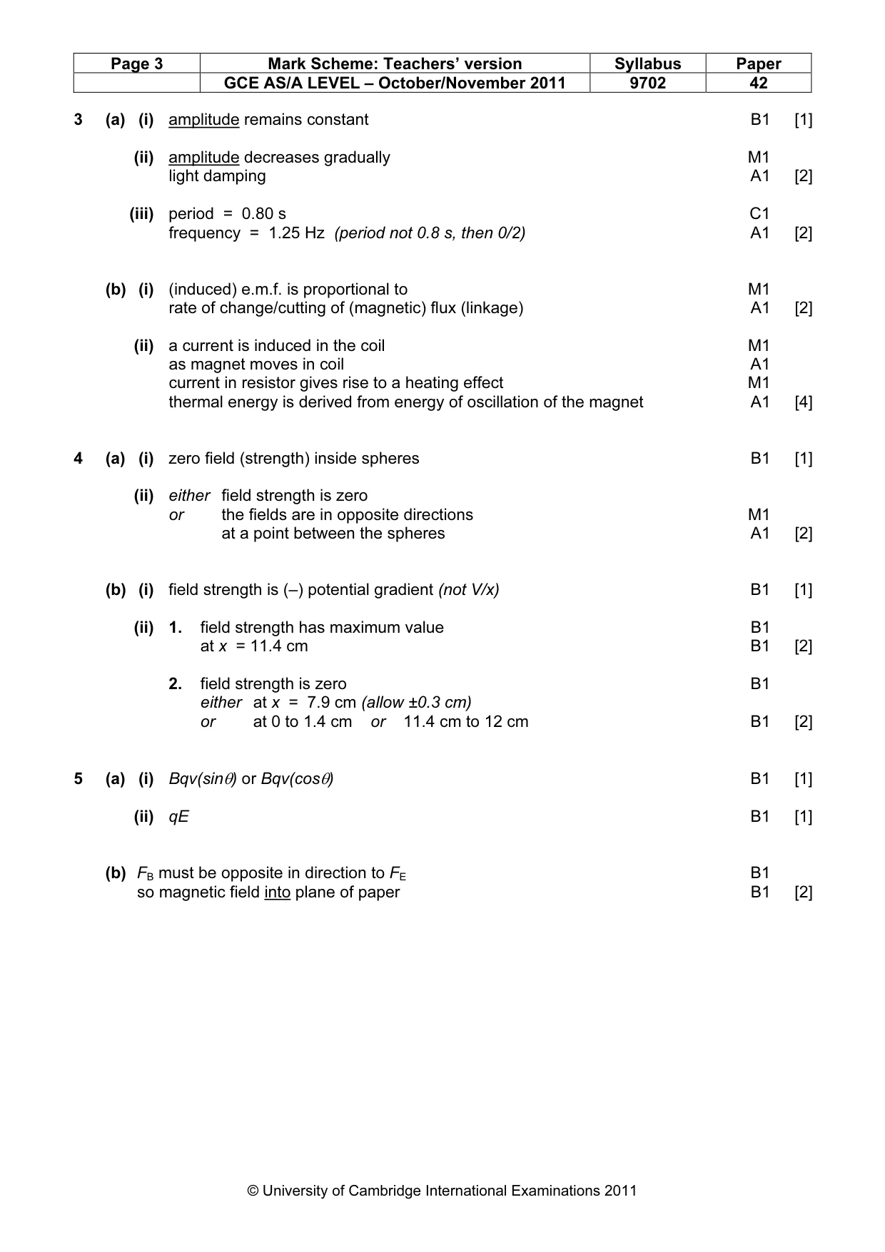
Mark scheme: 3 (a) (i) amplitude remains constant B1 [1] (ii) amplitude decreases gradually M1 light damping A1 [2] (iii) period = 0.80 s C1 frequency = 1.25 Hz (period not 0.8 s, then 0/2) A1 [2] (b) (i) (induced) e.m.f. is proportional to M1 rate of change/cutting of (magnetic) flux (linkage) A1 [2] (ii) a current is induced in the coil M1 as magnet moves in coil A1 current in resistor gives rise to a heating effect M1 thermal energy is derived from energy of oscillation of the magnet A1 [4]
Q4 · Two small charged metal spheres A and B are situated in a vacuum
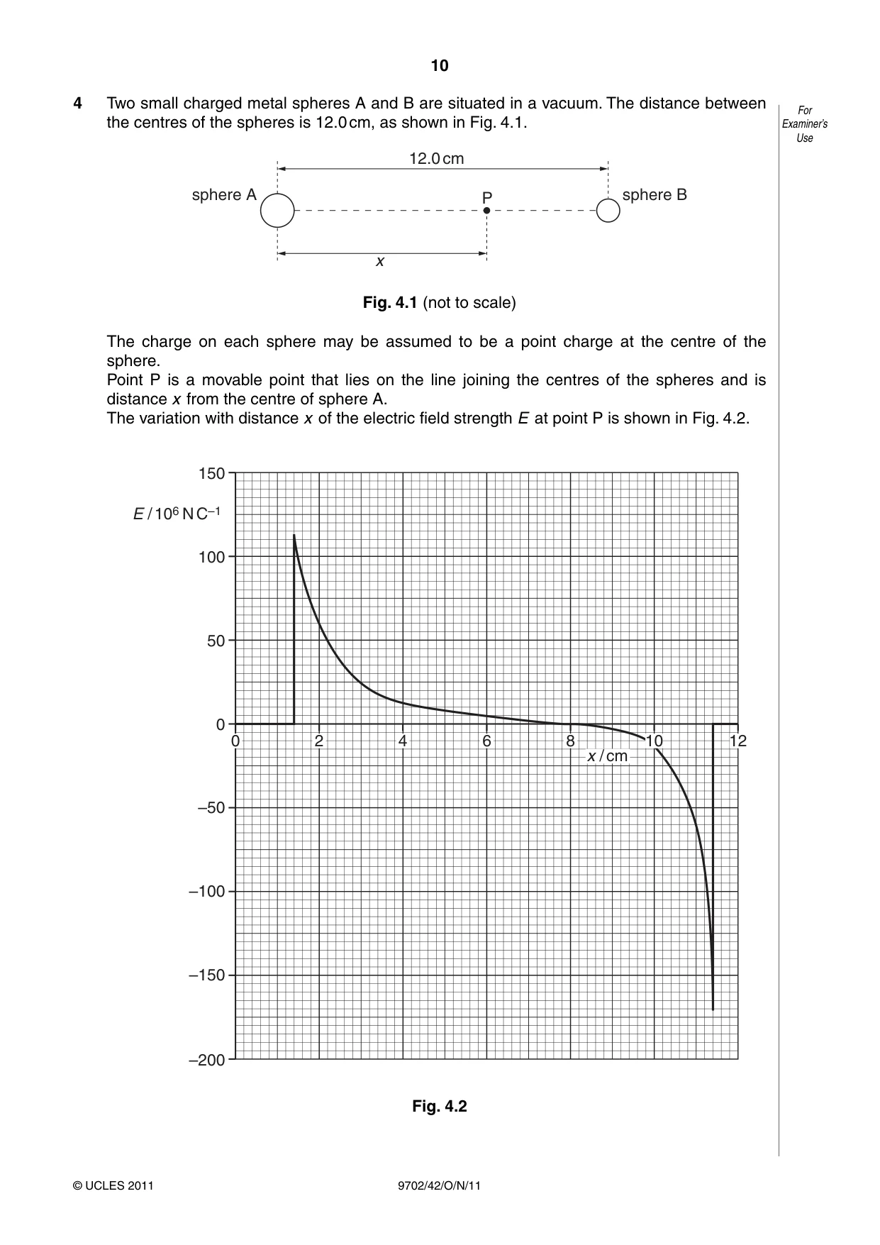
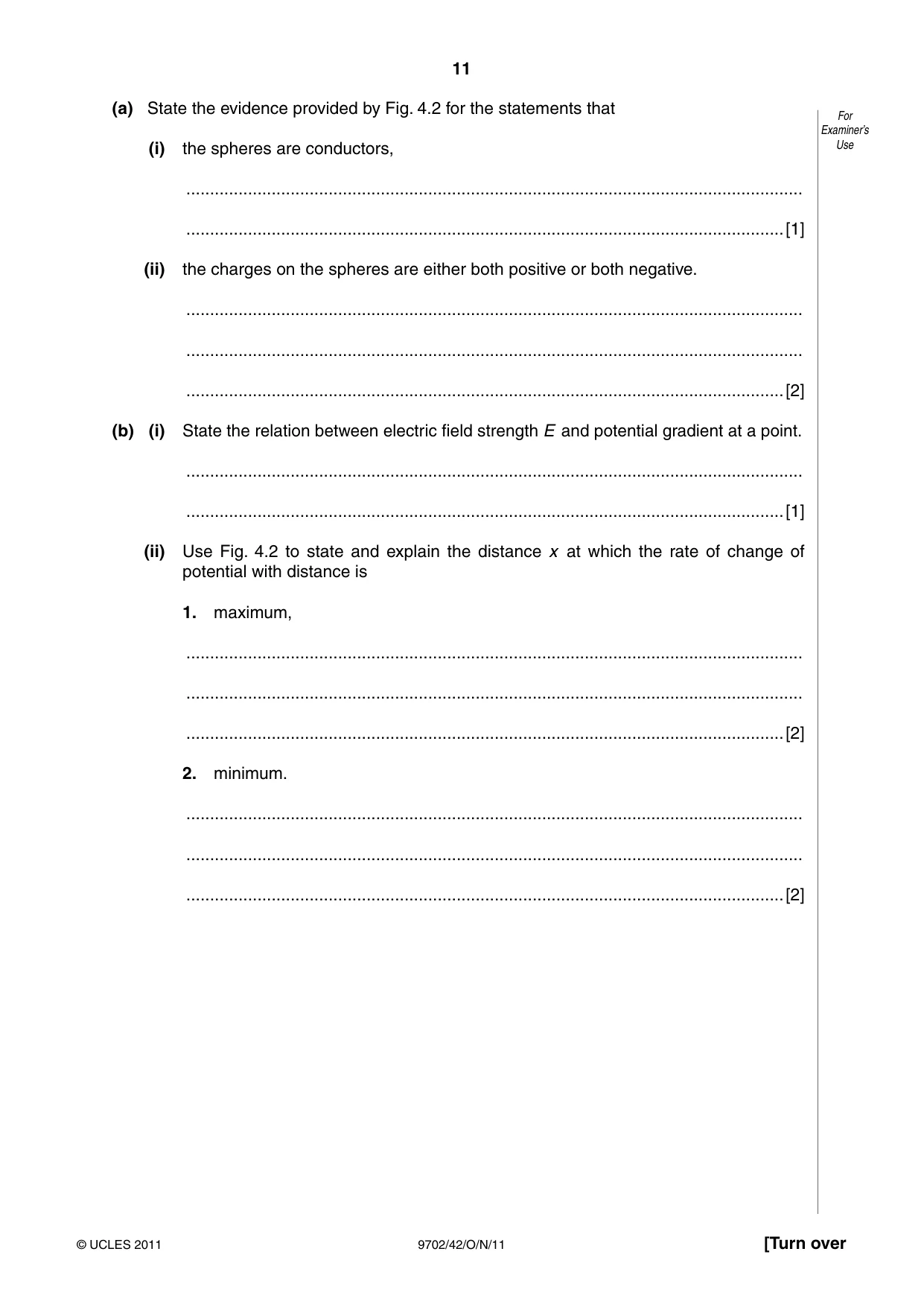
4 Two small charged metal spheres A and B are situated in a vacuum. The distance between For the centres of the spheres is 12.0 cm, as shown in Fig. 4.1. Examiner’s Use 12.0 cm sphere A P sphere B x Fig. 4.1 (not to scale) The charge on each sphere may be assumed to be a point charge at the centre of the sphere. Point P is a movable point that lies on the line joining the centres of the spheres and is distance x from the centre of sphere A. The variation with distance x of the electric field strength E at point P is shown in Fig. 4.2. 150 E / 106 N C–1 100 50 0 0 2 4 6 8 10 12 x / cm –50 –100 –150 –200 Fig. 4.2 (a) State the evidence provided by Fig. 4.2 for the statements that For Examiner’s (i) the spheres are conductors, Use .................................................................................................................................. ..............................................................................................................................[1] (ii) the charges on the spheres are either both positive or both negative. .................................................................................................................................. .................................................................................................................................. ..............................................................................................................................[2] (b) (i) State the relation between electric field strength E and potential gradient at a point. .................................................................................................................................. ..............................................................................................................................[1] (ii) Use Fig. 4.2 to state and explain the distance x at which the rate of change of potential with distance is 1. maximum, .................................................................................................................................. .................................................................................................................................. ..............................................................................................................................[2] 2. minimum. .................................................................................................................................. .................................................................................................................................. ..............................................................................................................................[2]
Mark scheme: 4 (a) (i) zero field (strength) inside spheres B1 [1] (ii) either field strength is zero or the fields are in opposite directions M1 at a point between the spheres A1 [2] (b) (i) field strength is (–) potential gradient (not V/x) B1 [1] (ii) 1. field strength has maximum value B1 at x = 11.4 cm B1 [2] 2. field strength is zero B1 either at x = 7.9 cm (allow ±0.3 cm) or at 0 to 1.4 cm or 11.4 cm to 12 cm B1 [2]
Q5 · Positively charged particles are travelling in a vacuum through three narrow slits S1, S2…
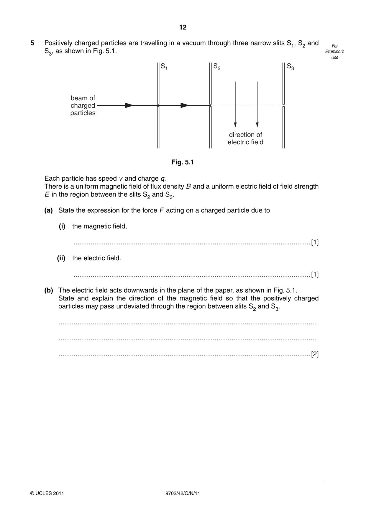
5 Positively charged particles are travelling in a vacuum through three narrow slits S1, S2 and For Examiner’s S3, as shown in Fig. 5.1. Use S1 S2 S3 beam of charged particles direction of electric field Fig. 5.1 Each particle has speed v and charge q. There is a uniform magnetic field of flux density B and a uniform electric field of field strength E in the region between the slits S2 and S3. (a) State the expression for the force F acting on a charged particle due to (i) the magnetic field, ..............................................................................................................................[1] (ii) the electric field. ..............................................................................................................................[1] (b) The electric field acts downwards in the plane of the paper, as shown in Fig. 5.1. State and explain the direction of the magnetic field so that the positively charged particles may pass undeviated through the region between slits S2 and S3. .......................................................................................................................................... .......................................................................................................................................... ......................................................................................................................................[2]
Mark scheme: 5 (a) (i) Bqv(sinθ) or Bqv(cosθ) B1 [1] (ii) qE B1 [1] (b) FB must be opposite in direction to FE B1 so magnetic field into plane of paper B1 [2] GCE AS/A LEVEL – October/November 2011 9702 42
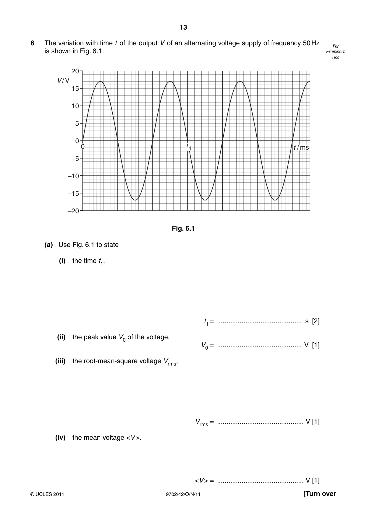
Q6 · The variation with time t of the output V of an alternating voltage supply of frequency…
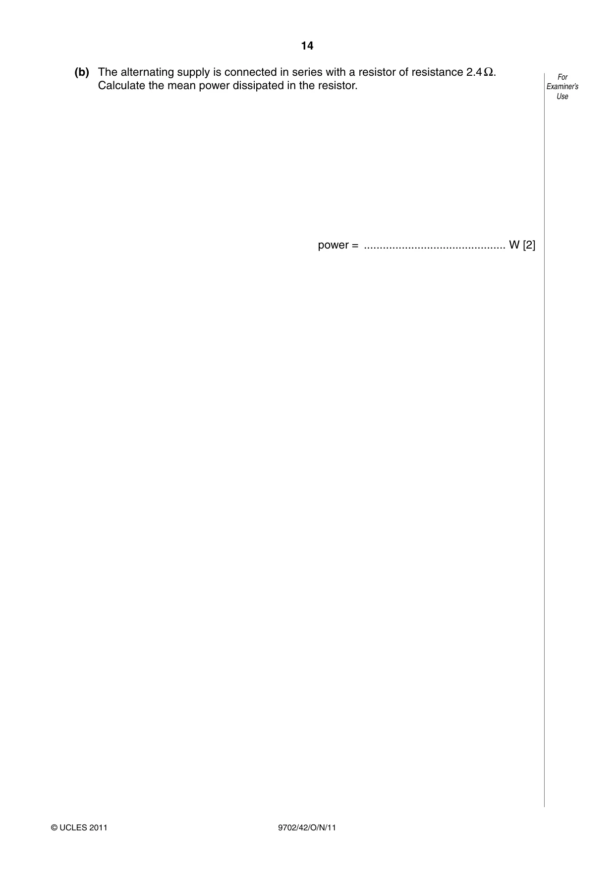
6 The variation with time t of the output V of an alternating voltage supply of frequency 50 Hz For is shown in Fig. 6.1. Examiner’s Use 20 V / V 15 10 5 0 0 t 1 t / ms –5 –10 –15 –20 Fig. 6.1 (a) Use Fig. 6.1 to state (i) the time t1, t1 = ............................................ s [2] (ii) the peak value V0 of the voltage, V0 = ............................................. V [1] (iii) the root-mean-square voltage Vrms, Vrms = .............................................. V [1] (iv) the mean voltage <V >. <V > = .............................................. V [1] (b) The alternating supply is connected in series with a resistor of resistance 2.4 Ω. For Calculate the mean power dissipated in the resistor. Examiner’s Use power = ............................................. W [2]
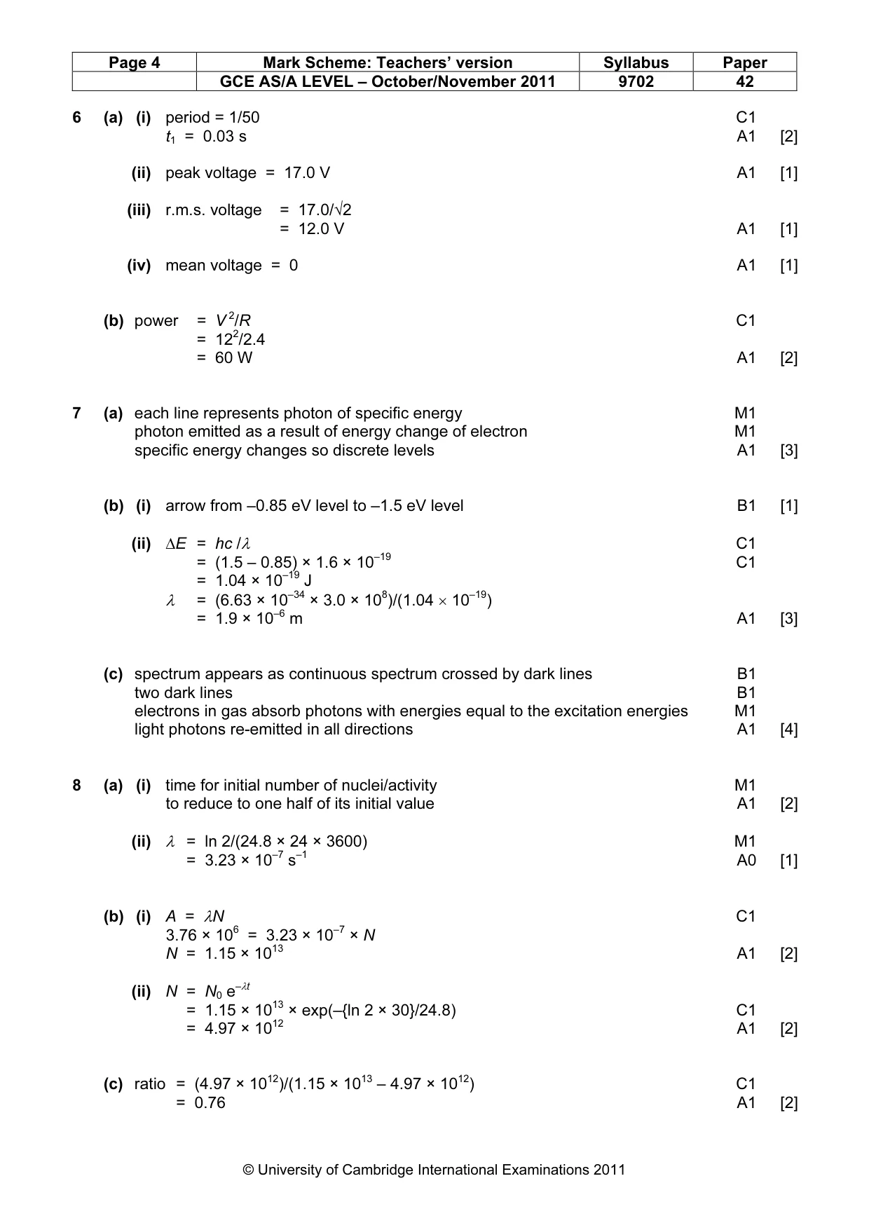
Mark scheme: 6 (a) (i) period = 1/50 C1 t1 = 0.03 s A1 [2] (ii) peak voltage = 17.0 V A1 [1] (iii) r.m.s. voltage = 17.0/√2 = 12.0 V A1 [1] (iv) mean voltage = 0 A1 [1] (b) power = V 2/R C1 = 122/2.4 = 60 W A1 [2]
Q7 · Explain how the line spectrum of hydrogen provides evidence for the existence of For…
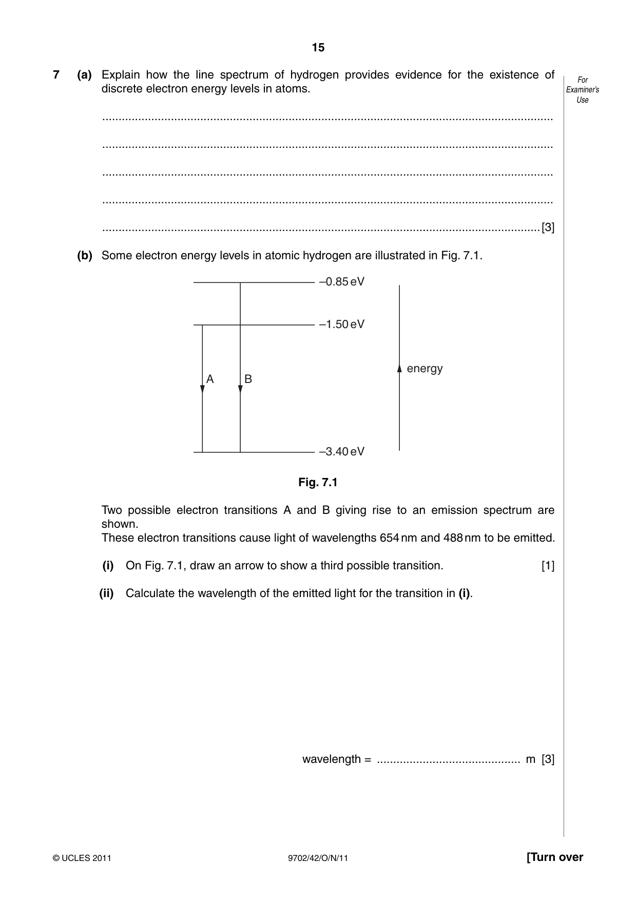
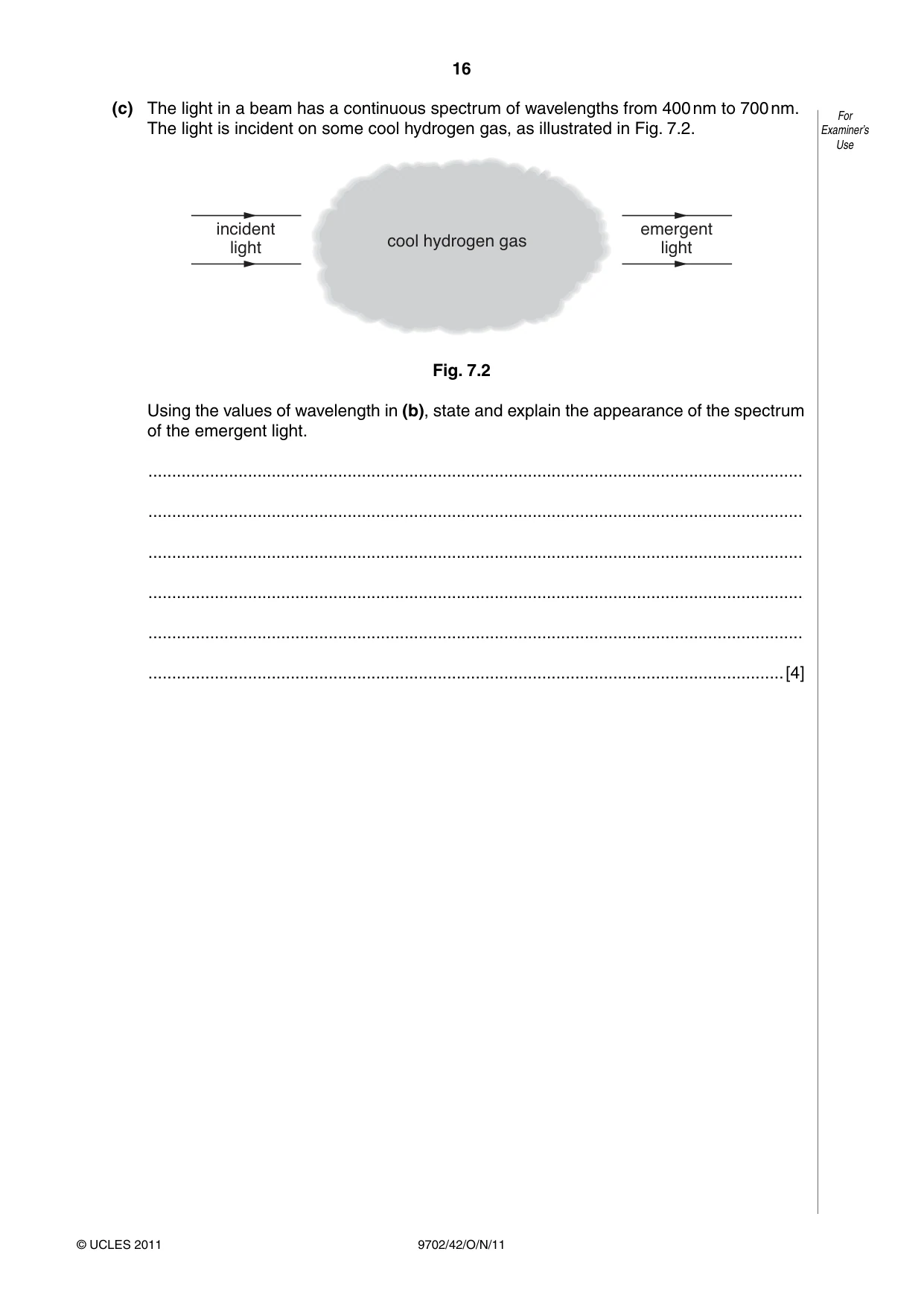
7 (a) Explain how the line spectrum of hydrogen provides evidence for the existence of For discrete electron energy levels in atoms. Examiner’s Use .......................................................................................................................................... .......................................................................................................................................... .......................................................................................................................................... .......................................................................................................................................... ......................................................................................................................................[3] (b) Some electron energy levels in atomic hydrogen are illustrated in Fig. 7.1. –0.85 eV –1.50 eV energy A B –3.40 eV Fig. 7.1 Two possible electron transitions A and B giving rise to an emission spectrum are shown. These electron transitions cause light of wavelengths 654 nm and 488 nm to be emitted. (i) On Fig. 7.1, draw an arrow to show a third possible transition. [1] (ii) Calculate the wavelength of the emitted light for the transition in (i). wavelength = ............................................ m [3] (c) The light in a beam has a continuous spectrum of wavelengths from 400 nm to 700 nm. For The light is incident on some cool hydrogen gas, as illustrated in Fig. 7.2. Examiner’s Use incident emergent cool hydrogen gas light light Fig. 7.2 Using the values of wavelength in (b), state and explain the appearance of the spectrum of the emergent light. .......................................................................................................................................... .......................................................................................................................................... .......................................................................................................................................... .......................................................................................................................................... .......................................................................................................................................... ......................................................................................................................................[4]
Mark scheme: 7 (a) each line represents photon of specific energy M1 photon emitted as a result of energy change of electron M1 specific energy changes so discrete levels A1 [3] (b) (i) arrow from –0.85 eV level to –1.5 eV level B1 [1] (ii) ∆E = hc /λ C1 = (1.5 – 0.85) × 1.6 × 10–19 C1 = 1.04 × 10⁻¹⁹ J λ = (6.63 × 10–34 × 3.0 × 108)/(1.04 × 10–19) = 1.9 × 10⁻⁶ m A1 [3] (c) spectrum appears as continuous spectrum crossed by dark lines B1 two dark lines B1 electrons in gas absorb photons with energies equal to the excitation energies M1 light photons re-emitted in all directions A1 [4]
Q8 · 33 For8 The isotope phosphorus-33 ( 15P) undergoes β-decay to form sulfur-33 ( 16S)…
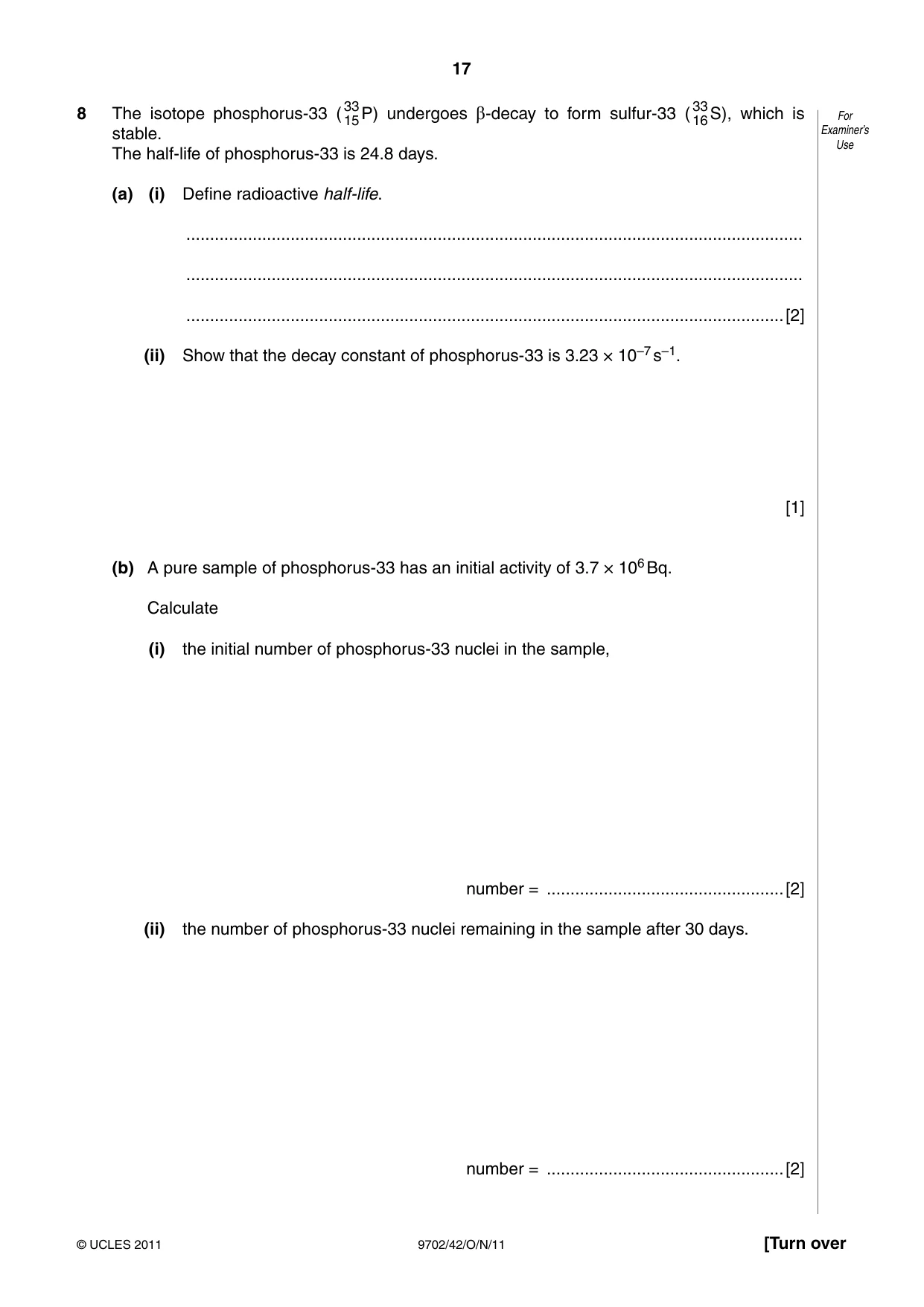
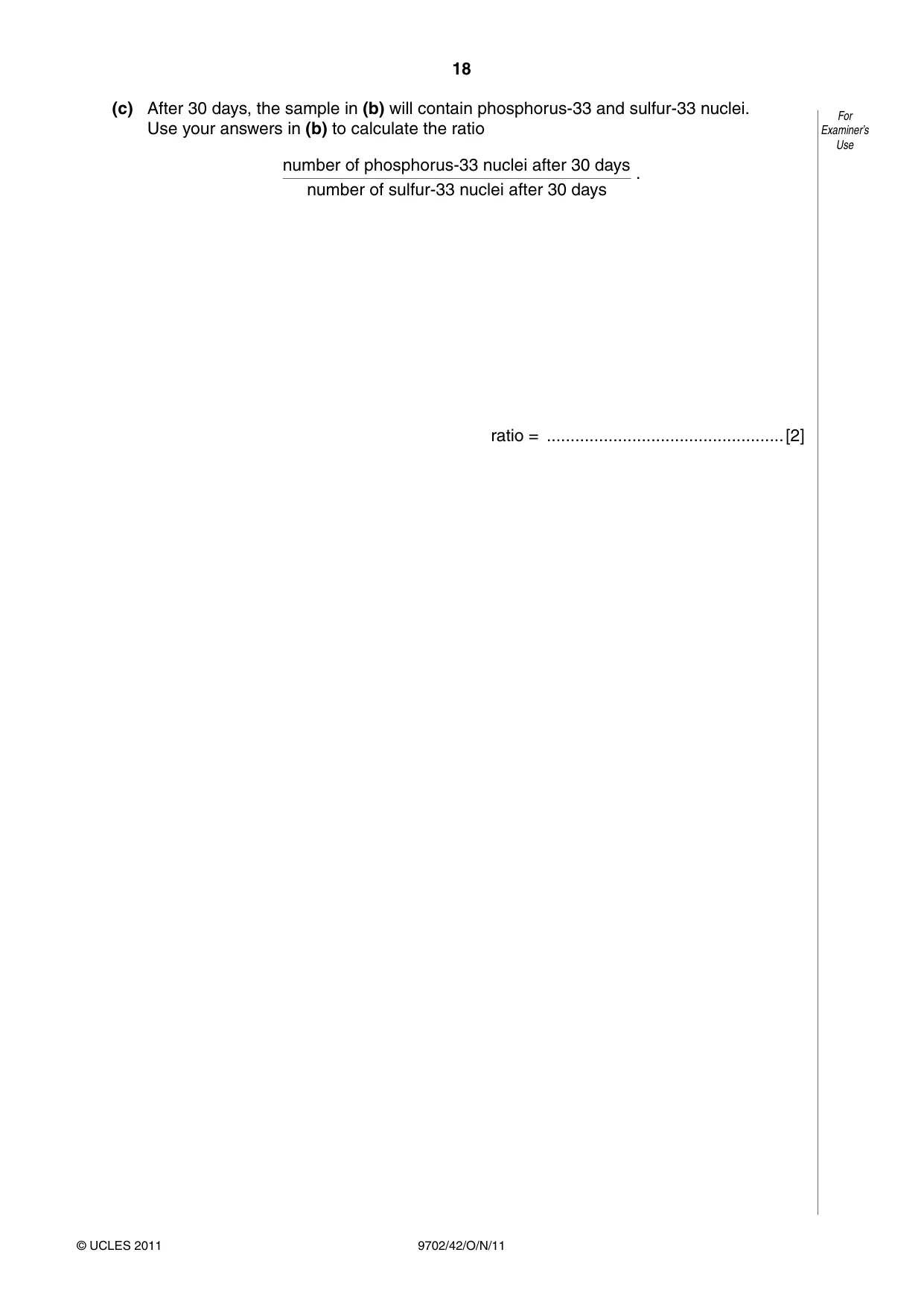
33 33 For8 The isotope phosphorus-33 ( 15P) undergoes β-decay to form sulfur-33 ( 16S), which is stable. Examiner’s Use The half-life of phosphorus-33 is 24.8 days. (a) (i) Define radioactive half-life. .................................................................................................................................. .................................................................................................................................. ..............................................................................................................................[2] (ii) Show that the decay constant of phosphorus-33 is 3.23 × 10⁻⁷ s–1. [1] (b) A pure sample of phosphorus-33 has an initial activity of 3.7 × 10⁶ Bq. Calculate (i) the initial number of phosphorus-33 nuclei in the sample, number = ..................................................[2] (ii) the number of phosphorus-33 nuclei remaining in the sample after 30 days. number = ..................................................[2] (c) After 30 days, the sample in (b) will contain phosphorus-33 and sulfur-33 nuclei. For Use your answers in (b) to calculate the ratio Examiner’s Use number of phosphorus-33 nuclei after 30 days . number of sulfur-33 nuclei after 30 days ratio = ..................................................[2]
Mark scheme: 8 (a) (i) time for initial number of nuclei/activity M1 to reduce to one half of its initial value A1 [2] (ii) λ = ln 2/(24.8 × 24 × 3600) M1 = 3.23 × 10⁻⁷ s–1 A0 [1] (b) (i) A = λN C1 3.76 × 106 = 3.23 × 10⁻⁷ × N N = 1.15 × 10¹³ A1 [2] (ii) N = N0 e–λt = 1.15 × 10¹³ × exp(–{ln 2 × 30}/24.8) C1 = 4.97 × 10¹² A1 [2] (c) ratio = (4.97 × 10¹²)/(1.15 × 1013 – 4.97 × 10¹²) C1 = 0.76 A1 [2] GCE AS/A LEVEL – October/November 2011 9702 42 Section B
Q9 · State two effects of negative feedback on the gain of an amplifier incorporating an…
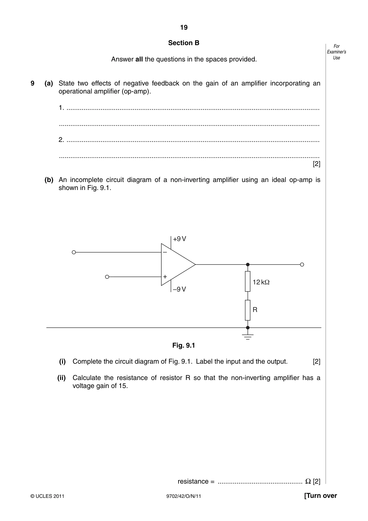
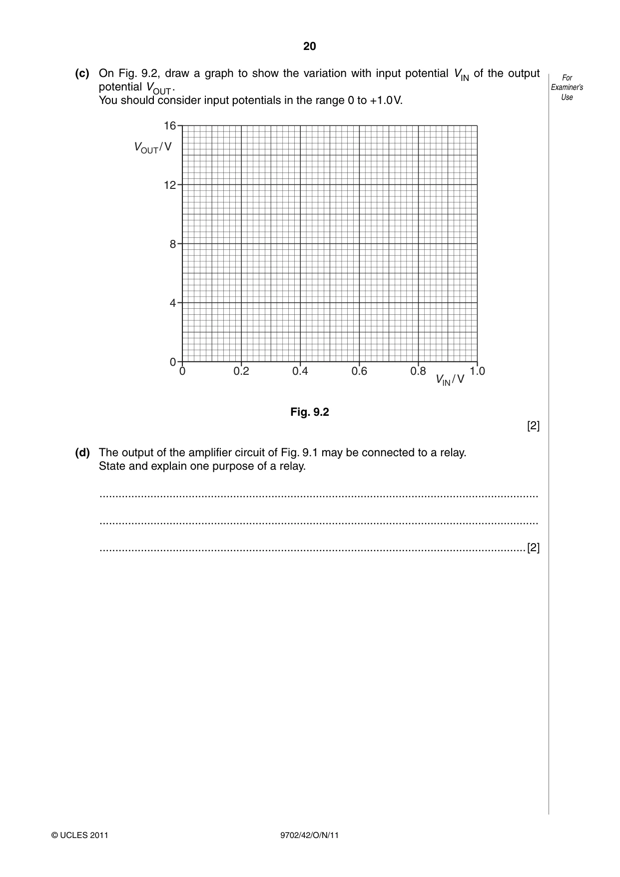
9 (a) State two effects of negative feedback on the gain of an amplifier incorporating an operational amplifier (op-amp). 1. ...................................................................................................................................... .......................................................................................................................................... 2. ...................................................................................................................................... .......................................................................................................................................... [2] (b) An incomplete circuit diagram of a non-inverting amplifier using an ideal op-amp is shown in Fig. 9.1. +9 V – + 12 kΩ –9 V R Fig. 9.1 (i) Complete the circuit diagram of Fig. 9.1. Label the input and the output. [2] (ii) Calculate the resistance of resistor R so that the non-inverting amplifier has a voltage gain of 15. resistance = ............................................. Ω [2] (c) On Fig. 9.2, draw a graph to show the variation with input potential VIN of the output For potential VOUT . Examiner’s You should consider input potentials in the range 0 to +1.0 V. Use 16 VOUT / V 12 8 4 0 0 0.2 0.4 0.6 0.8 1.0 VIN / V Fig. 9.2 [2] (d) The output of the amplifier circuit of Fig. 9.1 may be connected to a relay. State and explain one purpose of a relay. .......................................................................................................................................... .......................................................................................................................................... ......................................................................................................................................[2]
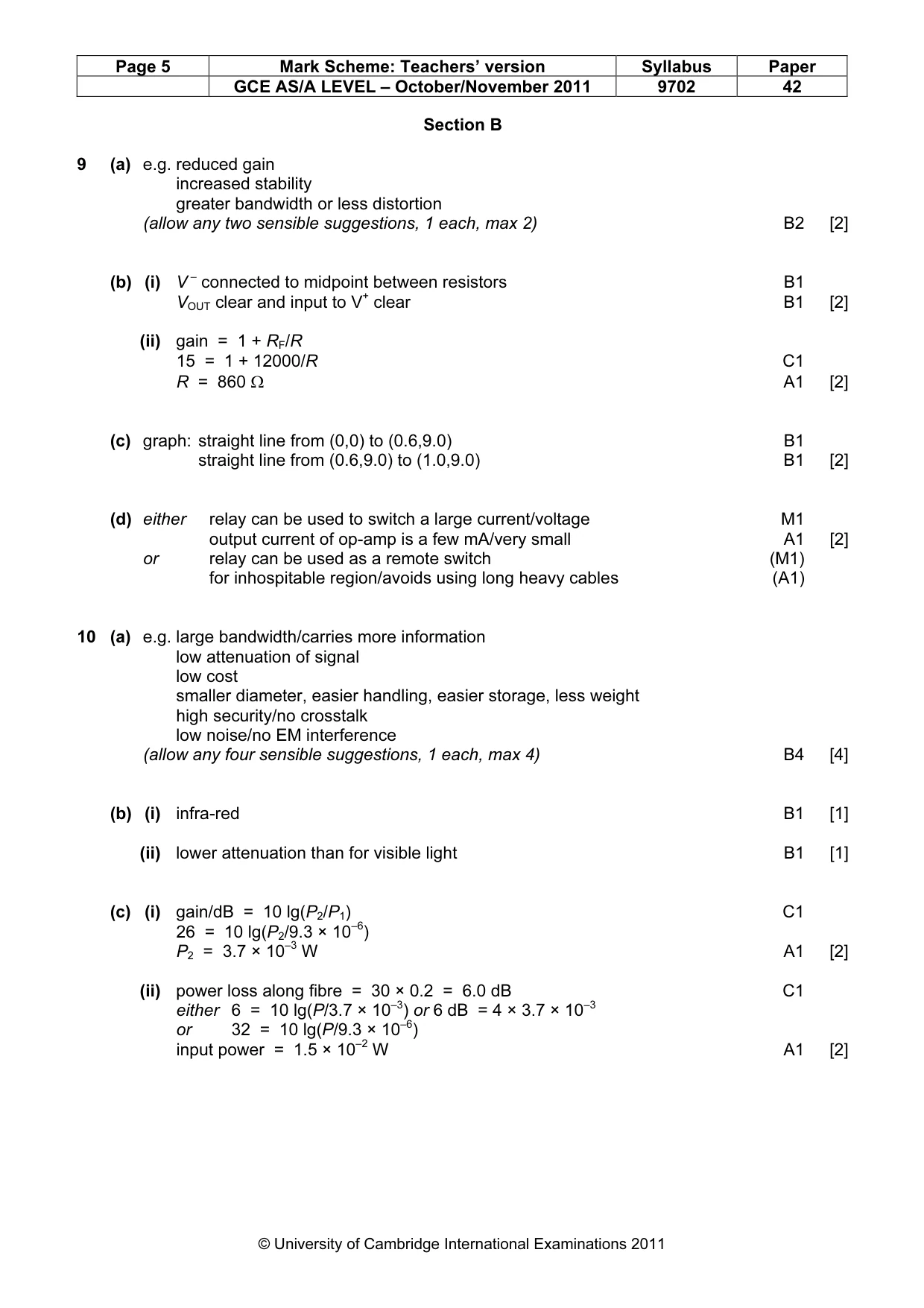
Mark scheme: 9 (a) e.g. reduced gain increased stability greater bandwidth or less distortion (allow any two sensible suggestions, 1 each, max 2) B2 [2] (b) (i) V – connected to midpoint between resistors B1 VOUT clear and input to V+ clear B1 [2] (ii) gain = 1 + RF/R 15 = 1 + 12000/R C1 R = 860 Ω A1 [2] (c) graph: straight line from (0,0) to (0.6,9.0) B1 straight line from (0.6,9.0) to (1.0,9.0) B1 [2] (d) either relay can be used to switch a large current/voltage M1 output current of op-amp is a few mA/very small A1 [2] or relay can be used as a remote switch (M1) for inhospitable region/avoids using long heavy cables (A1)
Q10 · Cable television uses optic fibres for the transmission of signals
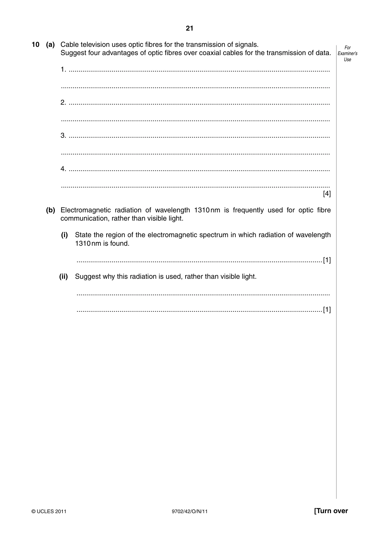
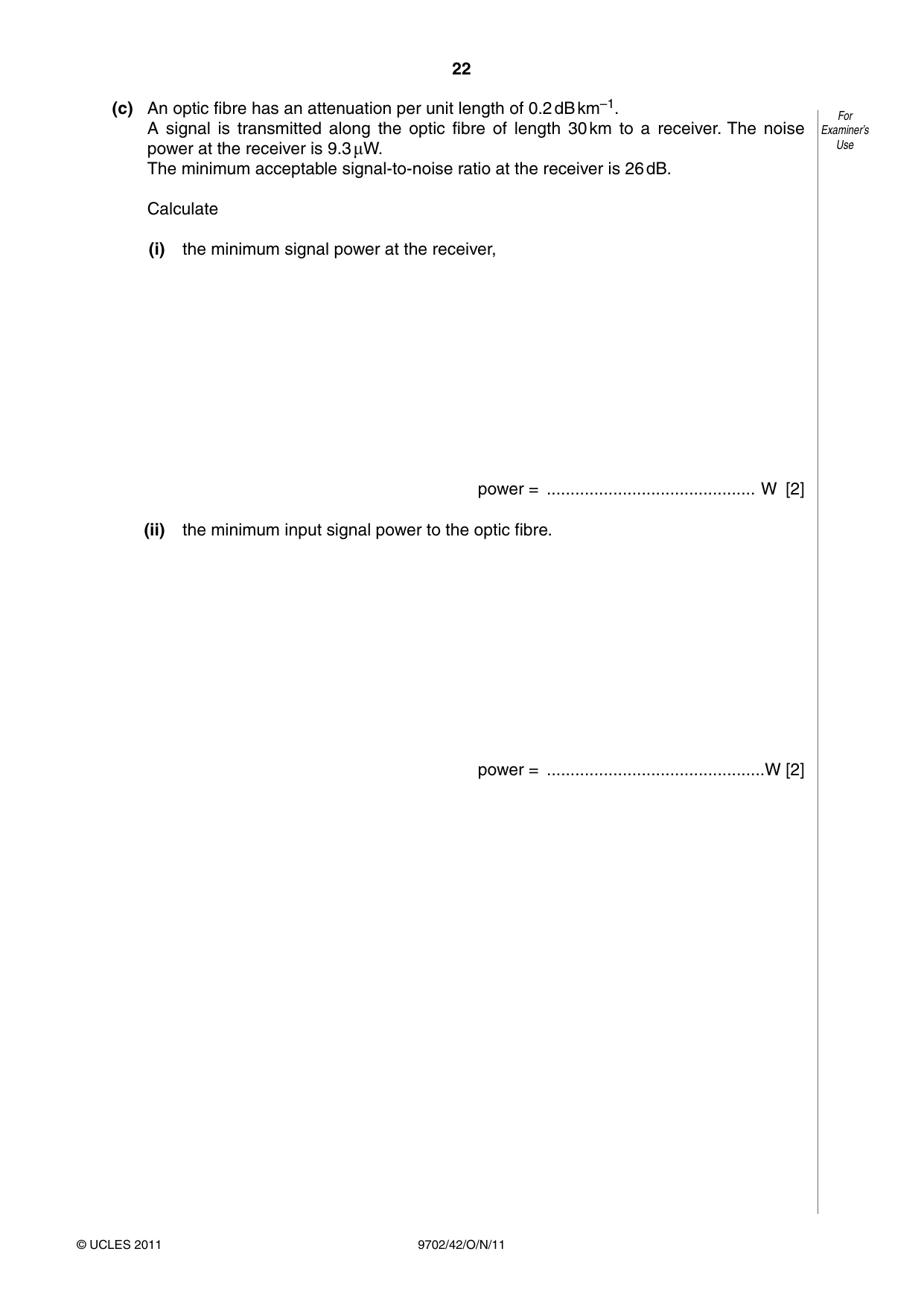
10 (a) Cable television uses optic fibres for the transmission of signals. For Suggest four advantages of optic fibres over coaxial cables for the transmission of data. Examiner’s Use 1. ...................................................................................................................................... .......................................................................................................................................... 2. ...................................................................................................................................... .......................................................................................................................................... 3. ...................................................................................................................................... .......................................................................................................................................... 4. ...................................................................................................................................... .......................................................................................................................................... [4] (b) Electromagnetic radiation of wavelength 1310 nm is frequently used for optic fibre communication, rather than visible light. (i) State the region of the electromagnetic spectrum in which radiation of wavelength 1310 nm is found. ..............................................................................................................................[1] (ii) Suggest why this radiation is used, rather than visible light. .................................................................................................................................. ..............................................................................................................................[1] (c) An optic fibre has an attenuation per unit length of 0.2 dB km–1. For A signal is transmitted along the optic fibre of length 30 km to a receiver. The noise Examiner’s power at the receiver is 9.3 μW. Use The minimum acceptable signal-to-noise ratio at the receiver is 26 dB. Calculate (i) the minimum signal power at the receiver, power = ............................................ W [2] (ii) the minimum input signal power to the optic fibre. power = ..............................................W [2]
Mark scheme: 10 (a) e.g. large bandwidth/carries more information low attenuation of signal low cost smaller diameter, easier handling, easier storage, less weight high security/no crosstalk low noise/no EM interference (allow any four sensible suggestions, 1 each, max 4) B4 [4] (b) (i) infra-red B1 [1] (ii) lower attenuation than for visible light B1 [1] (c) (i) gain/dB = 10 lg(P2/P1) C1 26 = 10 lg(P2/9.3 × 10–6) P2 = 3.7 × 10⁻³ W A1 [2] (ii) power loss along fibre = 30 × 0.2 = 6.0 dB C1 either 6 = 10 lg(P/3.7 × 10–3) or 6 dB = 4 × 3.7 × 10–3 or 32 = 10 lg(P/9.3 × 10–6) input power = 1.5 × 10⁻² W A1 [2] GCE AS/A LEVEL – October/November 2011 9702 42
Q11 · A simplified block diagram of a mobile phone handset is shown in Fig
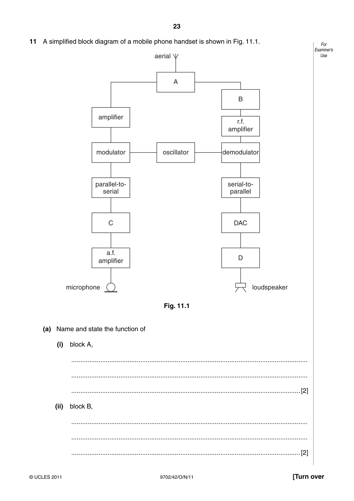
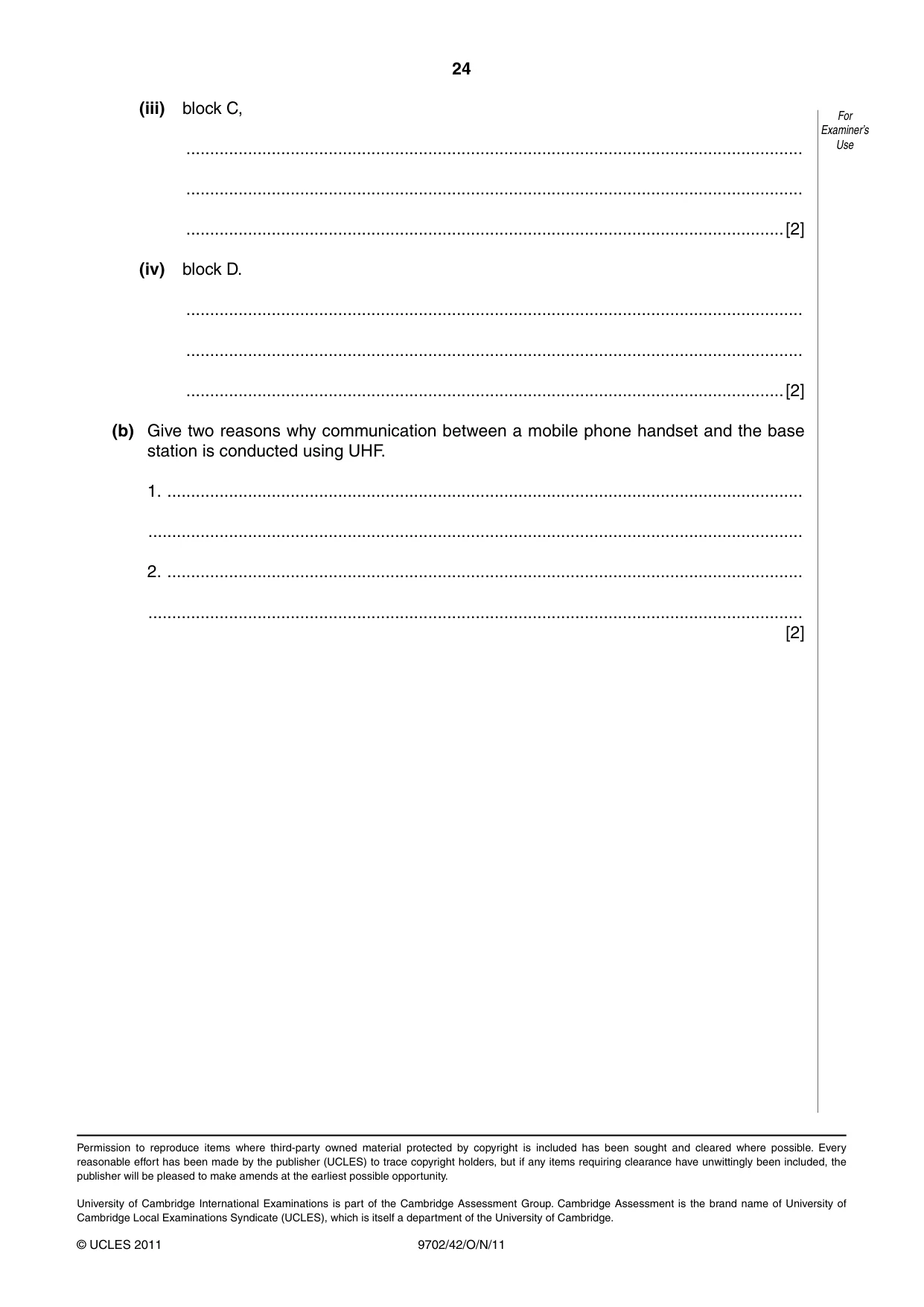
11 A simplified block diagram of a mobile phone handset is shown in Fig. 11.1. For Examiner’s aerial Use A B amplifier r.f. amplifier modulator oscillator demodulator parallel-to- serial-to- serial parallel C DAC a.f. D amplifier microphone loudspeaker Fig. 11.1 (a) Name and state the function of (i) block A, .................................................................................................................................. .................................................................................................................................. ..............................................................................................................................[2] (ii) block B, .................................................................................................................................. .................................................................................................................................. ..............................................................................................................................[2] (iii) block C, For Examiner’s .................................................................................................................................. Use .................................................................................................................................. ..............................................................................................................................[2] (iv) block D. .................................................................................................................................. .................................................................................................................................. ..............................................................................................................................[2] (b) Give two reasons why communication between a mobile phone handset and the base station is conducted using UHF. 1. ...................................................................................................................................... .......................................................................................................................................... 2. ...................................................................................................................................... .......................................................................................................................................... [2]
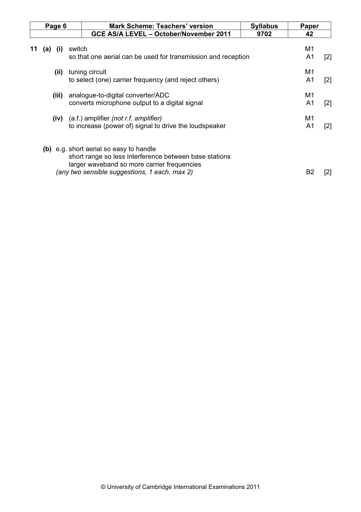
Mark scheme: 11 (a) (i) switch M1 so that one aerial can be used for transmission and reception A1 [2] (ii) tuning circuit M1 to select (one) carrier frequency (and reject others) A1 [2] (iii) analogue-to-digital converter/ADC M1 converts microphone output to a digital signal A1 [2] (iv) (a.f.) amplifier (not r.f. amplifier) M1 to increase (power of) signal to drive the loudspeaker A1 [2] (b) e.g. short aerial so easy to handle short range so less interference between base stations larger waveband so more carrier frequencies (any two sensible suggestions, 1 each, max 2) B2 [2]
What was in this paper
The subtopics covered by these 11 questions, and how many questions each got. Open one in a new tab to see every Cambridge question on it.
2Characteristics of alternating currents1Damped and forced oscillations, resonance1Electric force between point charges1Energy levels in atoms and line spectra1Force on a moving charge1Kinematics of uniform circular motion1Kinetic theory of gases1Practical circuits1Radioactive decay1What you needed in this session
Cambridge’s own grade thresholds for 2011 Oct/Nov, Paper 4 · Variant 2. A higher threshold means an easier paper — the bar moves with how the cohort did.