Cambridge A Level Physics 9702 — 2011 Oct/Nov Paper 4 · Variant 3
9702/43/O/N/11 · 12 questions · 100 marks · ≈113 min
The question paper and its mark scheme, free to read here and free to download. This is Cambridge’s own paper, exactly as it was sat.
Question paper24 pages
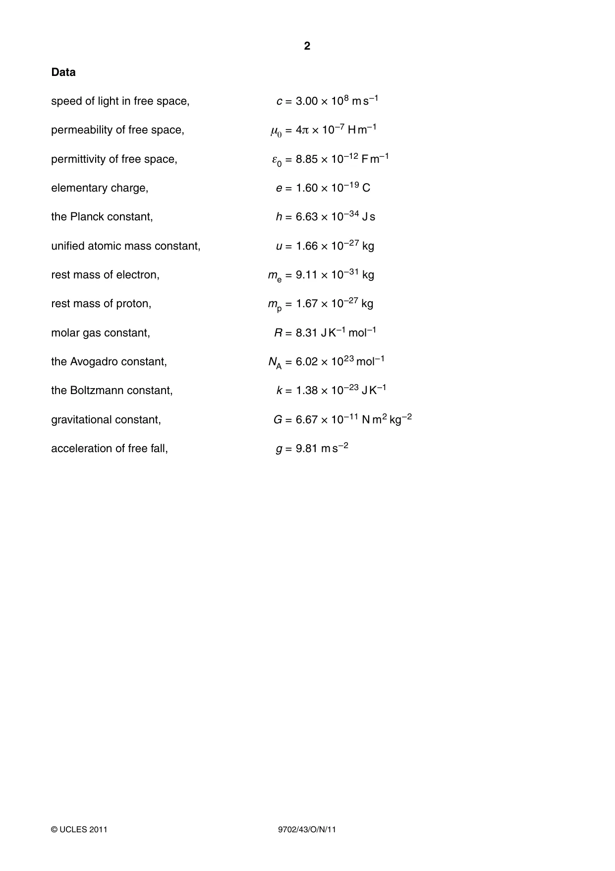
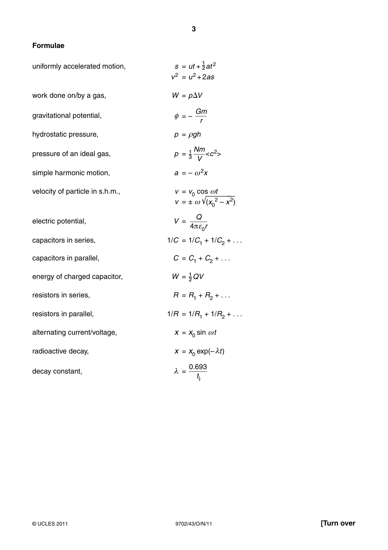

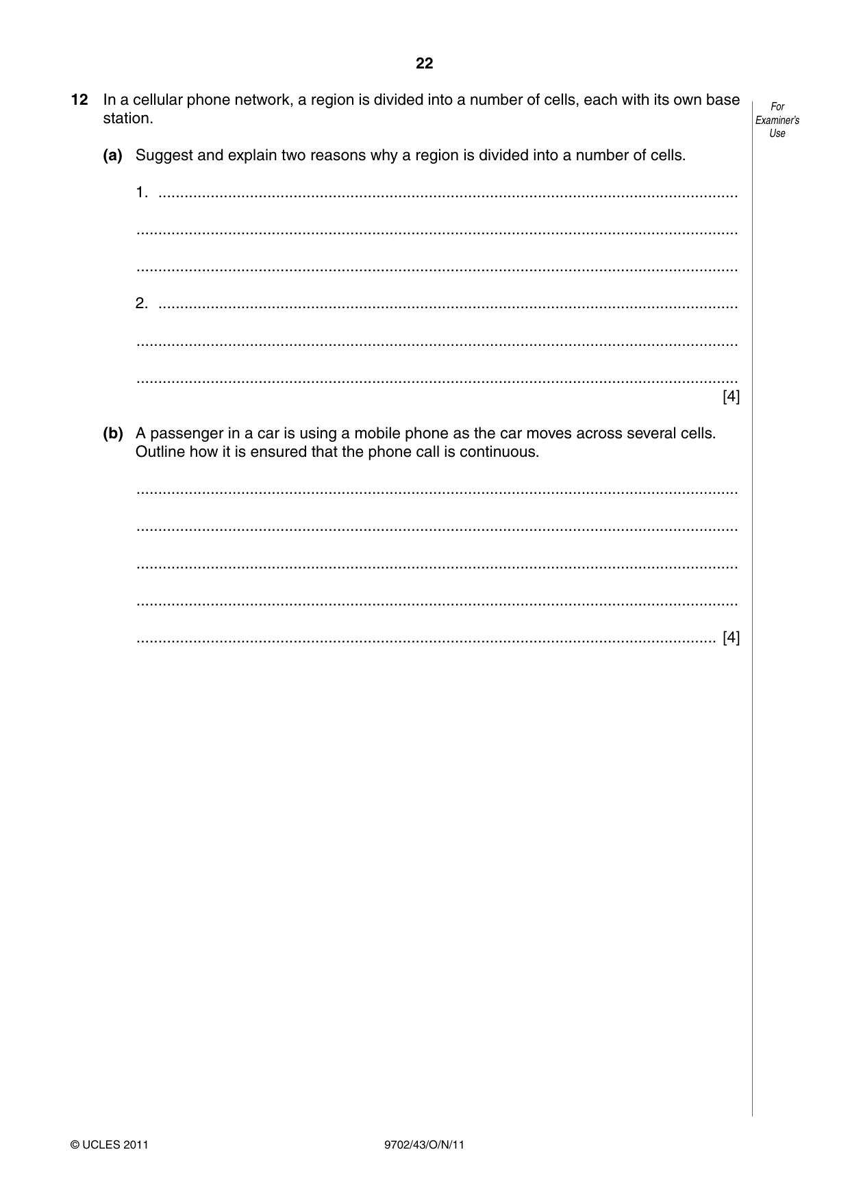


Mark scheme7 pages
Answers below. Sit the paper first if you are practising.
Questions as text
Q1 · The planet Mars may be considered to be an isolated sphere of diameter 6.79 × 10⁶ m with…
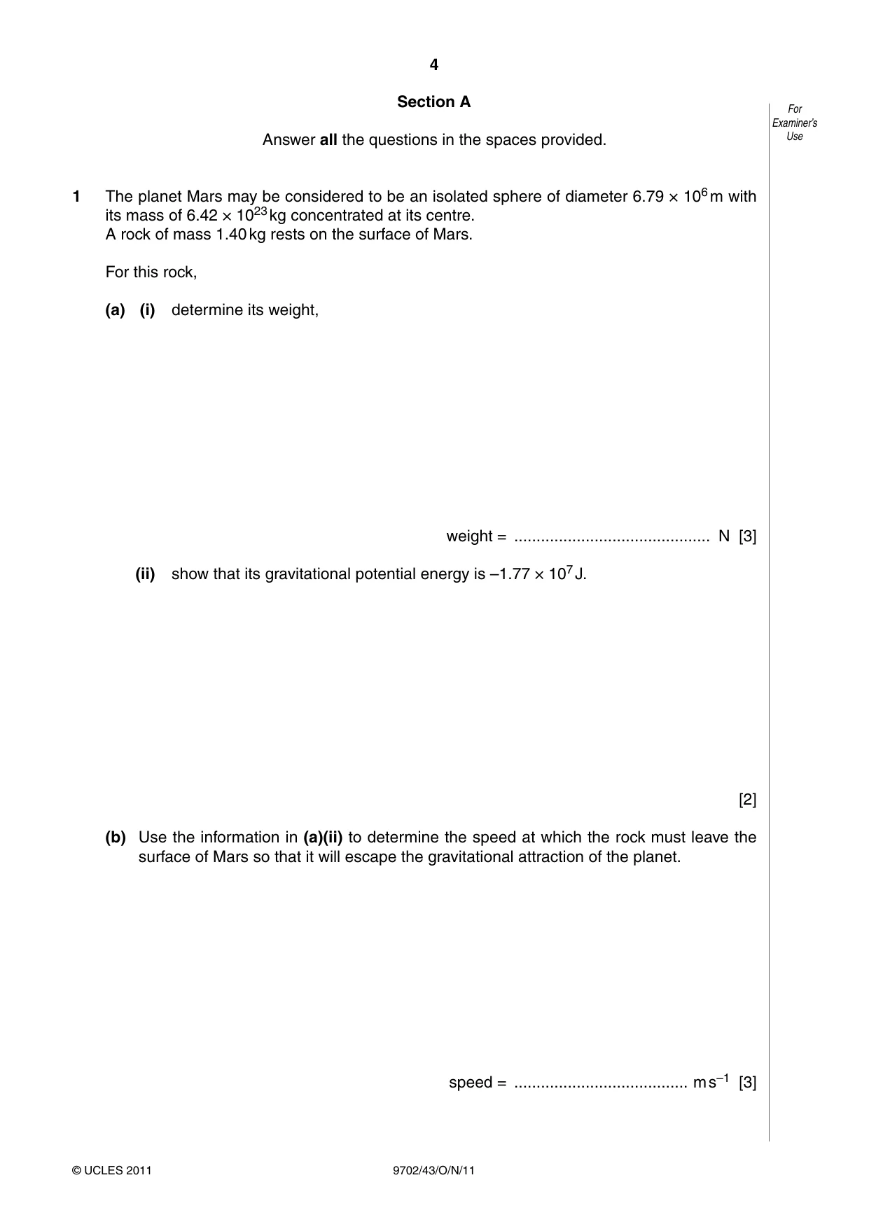
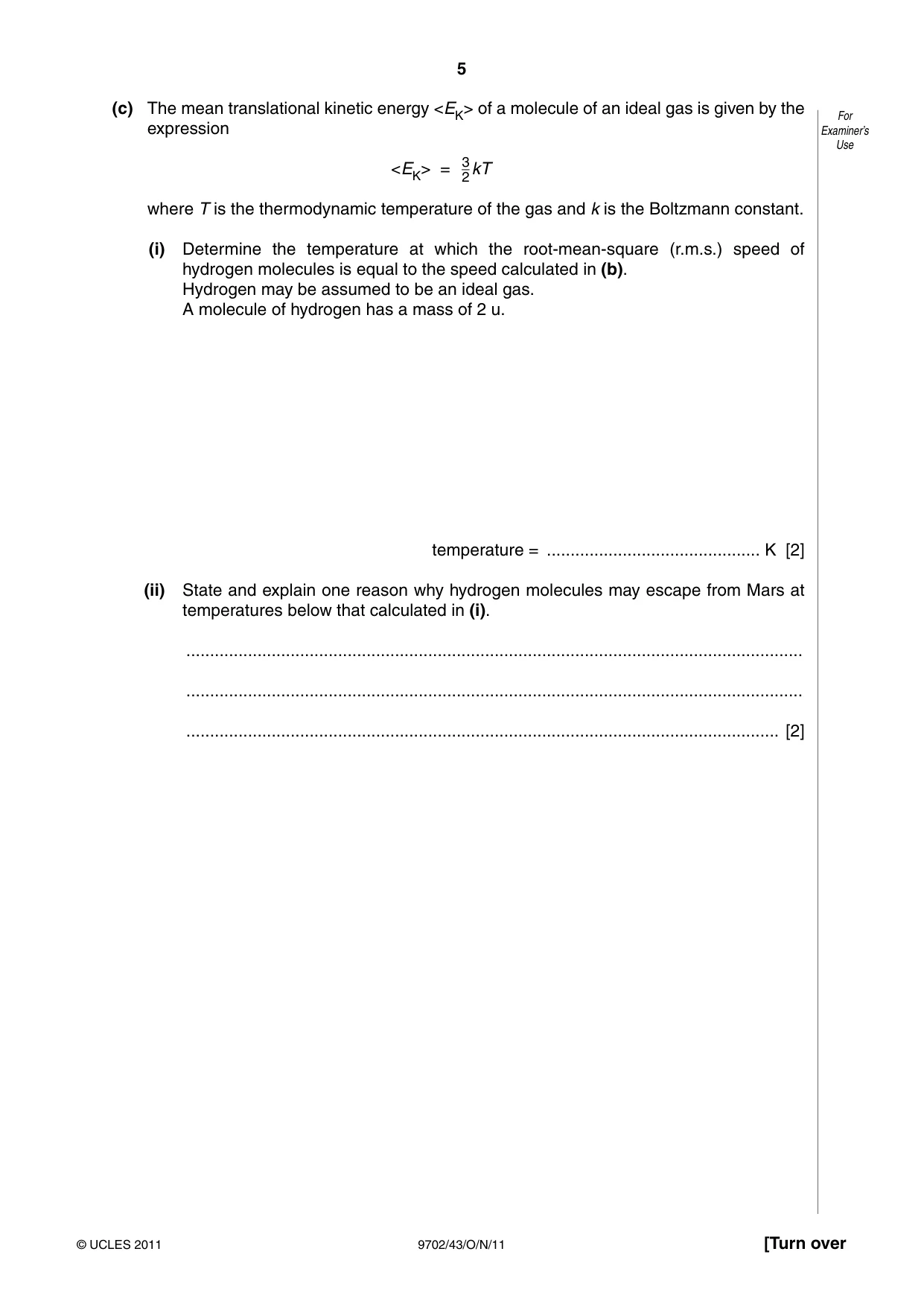
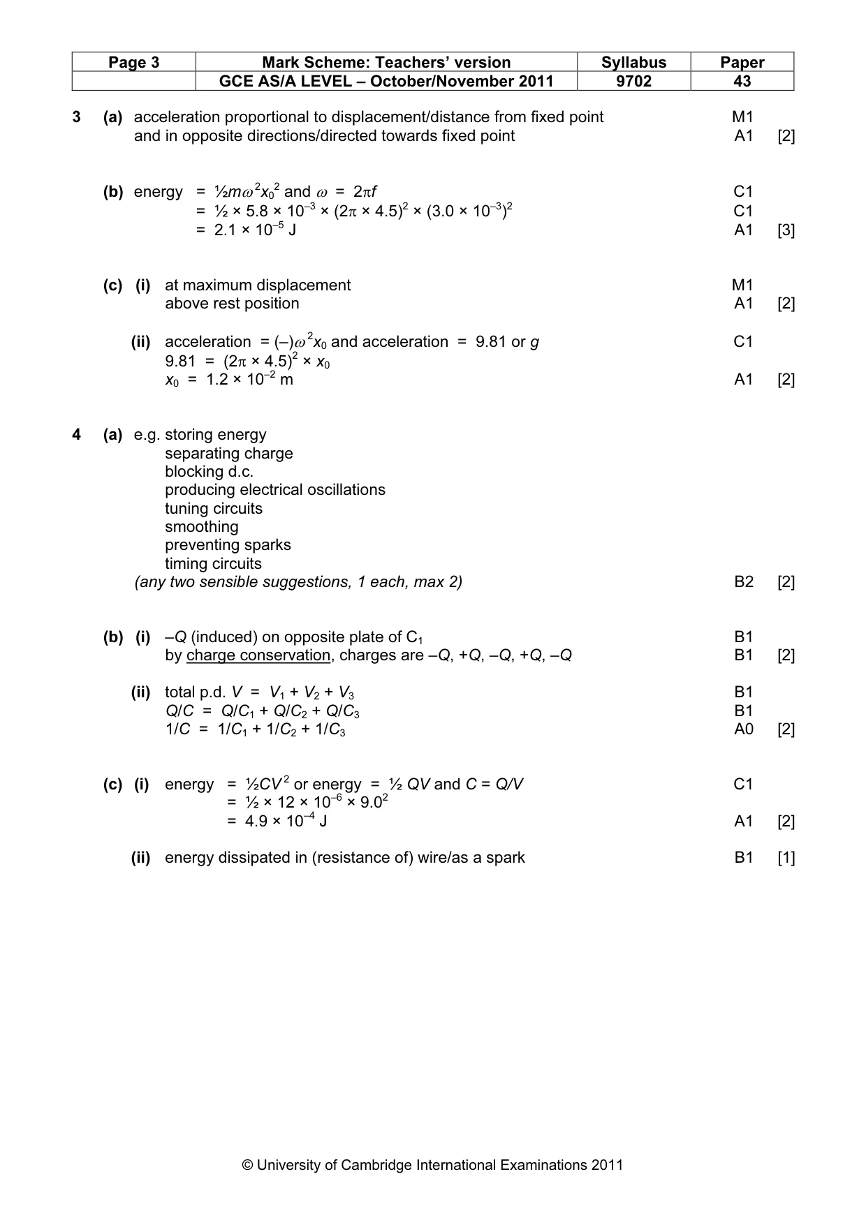
1 The planet Mars may be considered to be an isolated sphere of diameter 6.79 × 10⁶ m with its mass of 6.42 × 10²³ kg concentrated at its centre. A rock of mass 1.40 kg rests on the surface of Mars. For this rock, (a) (i) determine its weight, weight = ............................................ N [3] (ii) show that its gravitational potential energy is –1.77 × 10⁷ J. [2] (b) Use the information in (a)(ii) to determine the speed at which the rock must leave the surface of Mars so that it will escape the gravitational attraction of the planet. speed = ....................................... m s–1 [3] (c) The mean translational kinetic energy <EK> of a molecule of an ideal gas is given by the For expression Examiner’s Use <EK> = 32kT where T is the thermodynamic temperature of the gas and k is the Boltzmann constant. (i) Determine the temperature at which the root-mean-square (r.m.s.) speed of hydrogen molecules is equal to the speed calculated in (b). Hydrogen may be assumed to be an ideal gas. A molecule of hydrogen has a mass of 2 u. temperature = ............................................. K [2] (ii) State and explain one reason why hydrogen molecules may escape from Mars at temperatures below that calculated in (i). .................................................................................................................................. .................................................................................................................................. ............................................................................................................................. [2]
Mark scheme: 1 (a) (i) weight = GMm/r 2 C1 = (6.67 × 10–11 × 6.42 × 1023 × 1.40)/(½ × 6.79 × 10⁶)2 C1 = 5.20 N A1 [3] (ii) potential energy = –GMm/r C1 = –(6.67 × 10–11 × 6.42 × 1023 × 1.40)/(½ × 6.79 × 10⁶) M1 = –1.77 × 10⁷ J A0 [2] (b) either ½mv 2 = 1.77 × 10⁷ C1 v 2 = (1.77 × 107 × 2)/1.40 C1 v = 5.03 × 10³ m s–1 A1 or ½mv 2 = GMm/r (C1) v 2 = (2 × 6.67 x 10–11 × 6.42 × 1023)/(6.79 × 106/2) (C1) v = 5.02 × 10³ m s–1 (A1) [3] 3 (c) (i) ½ × 2 × 1.66 × 10–27 × (5.03 × 103)2 = × 1.38 × 10⁻²³ × T C1 2 T = 2030 K A1 [2] (ii) either because there is a range of speeds M1 some molecules have a higher speed A1 or some escape from point above planet surface (M1) so initial potential energy is higher (A1) [2]
Q2 · A resistance thermometer and a thermocouple thermometer are both used at the same For…
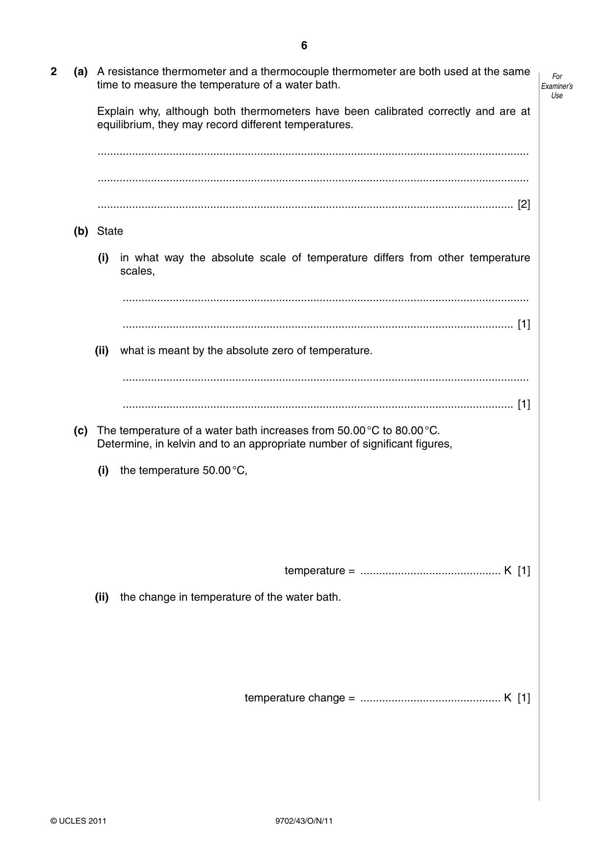
2 (a) A resistance thermometer and a thermocouple thermometer are both used at the same For time to measure the temperature of a water bath. Examiner’s Use Explain why, although both thermometers have been calibrated correctly and are at equilibrium, they may record different temperatures. .......................................................................................................................................... .......................................................................................................................................... ..................................................................................................................................... [2] (b) State (i) in what way the absolute scale of temperature differs from other temperature scales, .................................................................................................................................. ............................................................................................................................. [1] (ii) what is meant by the absolute zero of temperature. .................................................................................................................................. ............................................................................................................................. [1] (c) The temperature of a water bath increases from 50.00 °C to 80.00 °C. Determine, in kelvin and to an appropriate number of significant figures, (i) the temperature 50.00 °C, temperature = ............................................. K [1] (ii) the change in temperature of the water bath. temperature change = ............................................. K [1]
Mark scheme: 2 (a) temperature scale calibrated assuming linear change of property with temperature B1 neither property varies linearly with temperature B1 [2] (b) (i) does not depend on the property of a substance B1 [1] (ii) temperature at which atoms have minimum/zero energy B1 [1] (c) (i) 323.15 K A1 [1] (ii) 30.00 K A1 [1] GCE AS/A LEVEL – October/November 2011 9702 43
Q3 · Define simple harmonic motion
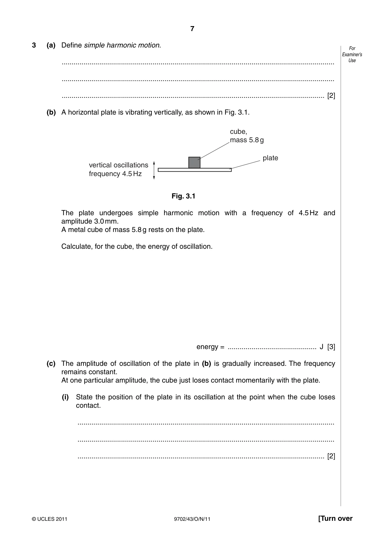
3 (a) Define simple harmonic motion. For Examiner’s .......................................................................................................................................... Use .......................................................................................................................................... ..................................................................................................................................... [2] (b) A horizontal plate is vibrating vertically, as shown in Fig. 3.1. cube, mass 5.8 g plate vertical oscillations frequency 4.5 Hz Fig. 3.1 The plate undergoes simple harmonic motion with a frequency of 4.5 Hz and amplitude 3.0 mm. A metal cube of mass 5.8 g rests on the plate. Calculate, for the cube, the energy of oscillation. energy = ............................................. J [3] (c) The amplitude of oscillation of the plate in (b) is gradually increased. The frequency remains constant. At one particular amplitude, the cube just loses contact momentarily with the plate. (i) State the position of the plate in its oscillation at the point when the cube loses contact. .................................................................................................................................. .................................................................................................................................. ............................................................................................................................. [2] (ii) Calculate this amplitude of oscillation. For Examiner’s Use amplitude = ............................................ m [2]
Mark scheme: 3 (a) acceleration proportional to displacement/distance from fixed point M1 and in opposite directions/directed towards fixed point A1 [2] (b) energy = ½mω 2x02 and ω = 2πf C1 = ½ × 5.8 × 10–3 × (2π × 4.5)2 × (3.0 × 10–3)2 C1 = 2.1 × 10⁻⁵ J A1 [3] (c) (i) at maximum displacement M1 above rest position A1 [2] (ii) acceleration = (–)ω 2x0 and acceleration = 9.81 or g C1 9.81 = (2π × 4.5)2 × x0 x0 = 1.2 × 10⁻² m A1 [2]
Q4 · State two functions of capacitors in electrical circuits
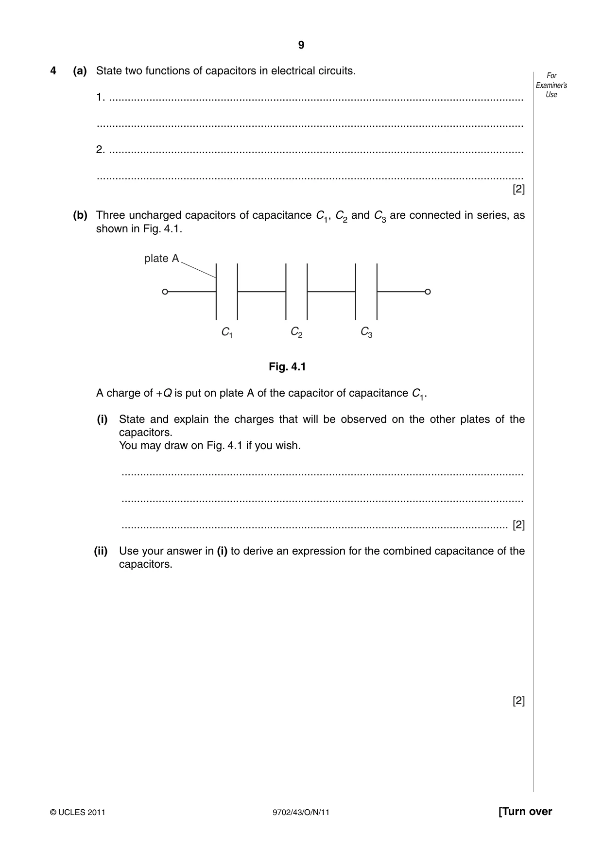
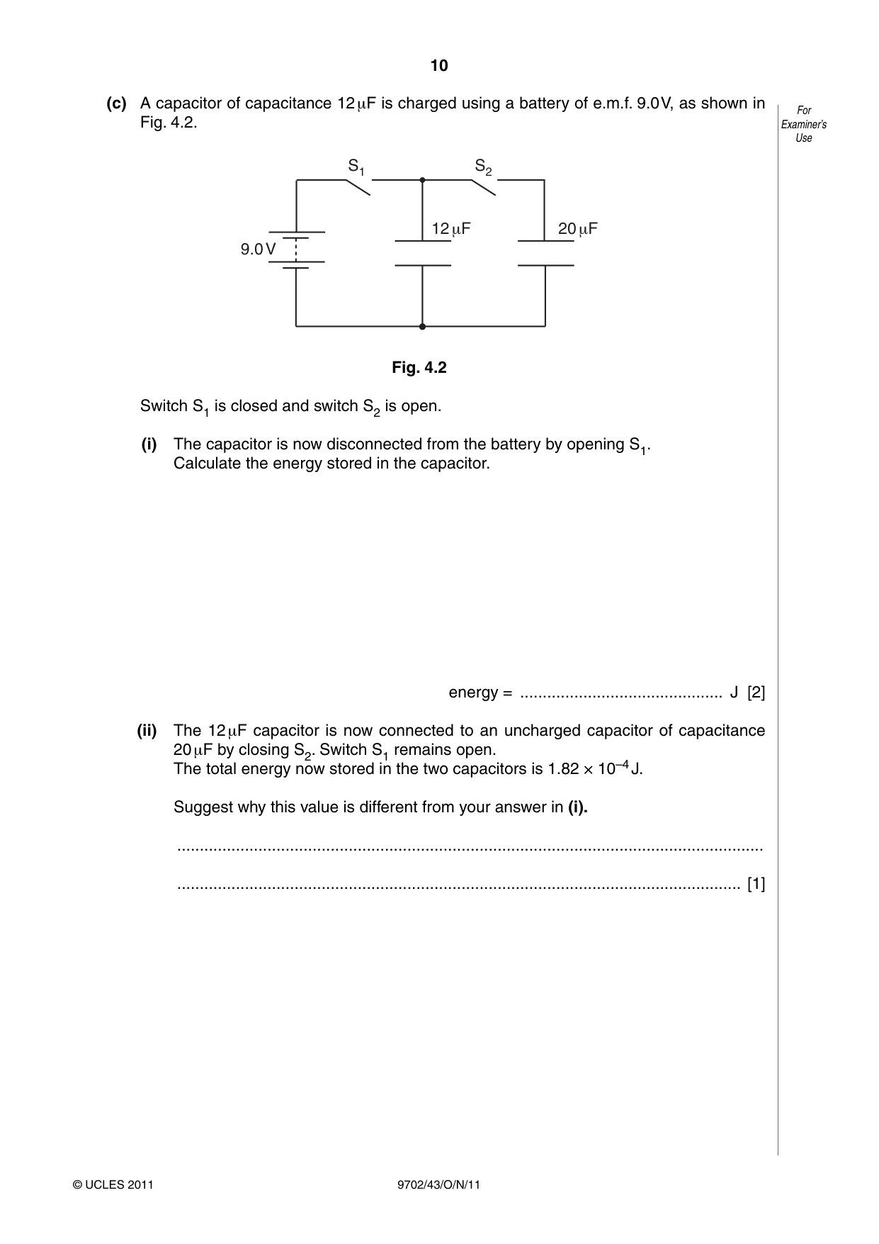
4 (a) State two functions of capacitors in electrical circuits. For Examiner’s 1. ...................................................................................................................................... Use .......................................................................................................................................... 2. ...................................................................................................................................... .......................................................................................................................................... [2] (b) Three uncharged capacitors of capacitance C1, C2 and C3 are connected in series, as shown in Fig. 4.1. plate A C1 C2 C3 Fig. 4.1 A charge of +Q is put on plate A of the capacitor of capacitance C1. (i) State and explain the charges that will be observed on the other plates of the capacitors. You may draw on Fig. 4.1 if you wish. .................................................................................................................................. .................................................................................................................................. ............................................................................................................................. [2] (ii) Use your answer in (i) to derive an expression for the combined capacitance of the capacitors. [2] (c) A capacitor of capacitance 12 μF is charged using a battery of e.m.f. 9.0 V, as shown in For Fig. 4.2. Examiner’s Use S1 S2 12 μF 20 μF 9.0 V Fig. 4.2 Switch S1 is closed and switch S2 is open. (i) The capacitor is now disconnected from the battery by opening S1. Calculate the energy stored in the capacitor. energy = ............................................. J [2] (ii) The 12 μF capacitor is now connected to an uncharged capacitor of capacitance 20 μF by closing S2. Switch S1 remains open. The total energy now stored in the two capacitors is 1.82 × 10⁻⁴ J. Suggest why this value is different from your answer in (i). .................................................................................................................................. ............................................................................................................................. [1]
Mark scheme: 4 (a) e.g. storing energy separating charge blocking d.c. producing electrical oscillations tuning circuits smoothing preventing sparks timing circuits (any two sensible suggestions, 1 each, max 2) B2 [2] (b) (i) –Q (induced) on opposite plate of C1 B1 by charge conservation, charges are –Q, +Q, –Q, +Q, –Q B1 [2] (ii) total p.d. V = V1 + V2 + V3 B1 Q/C = Q/C1 + Q/C2 + Q/C3 B1 1/C = 1/C1 + 1/C2 + 1/C3 A0 [2] (c) (i) energy = ½CV 2 or energy = ½ QV and C = Q/V C1 = ½ × 12 × 10–6 × 9.02 = 4.9 × 10⁻⁴ J A1 [2] (ii) energy dissipated in (resistance of) wire/as a spark B1 [1] GCE AS/A LEVEL – October/November 2011 9702 43
Q5 · The components for a bridge rectifier are shown in Fig
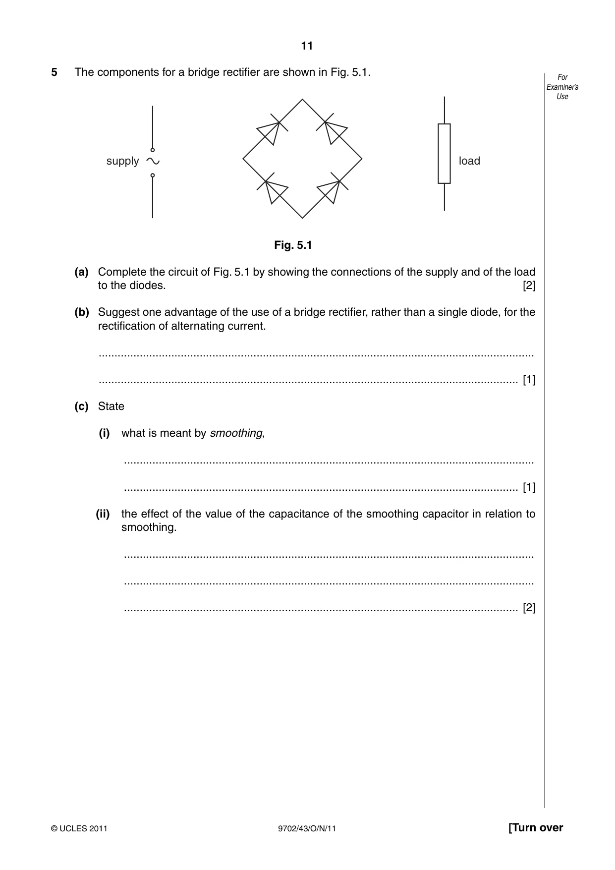
5 The components for a bridge rectifier are shown in Fig. 5.1. For Examiner’s Use supply load Fig. 5.1 (a) Complete the circuit of Fig. 5.1 by showing the connections of the supply and of the load to the diodes. [2] (b) Suggest one advantage of the use of a bridge rectifier, rather than a single diode, for the rectification of alternating current. .......................................................................................................................................... ..................................................................................................................................... [1] (c) State (i) what is meant by smoothing, .................................................................................................................................. ............................................................................................................................. [1] (ii) the effect of the value of the capacitance of the smoothing capacitor in relation to smoothing. .................................................................................................................................. .................................................................................................................................. ............................................................................................................................. [2]
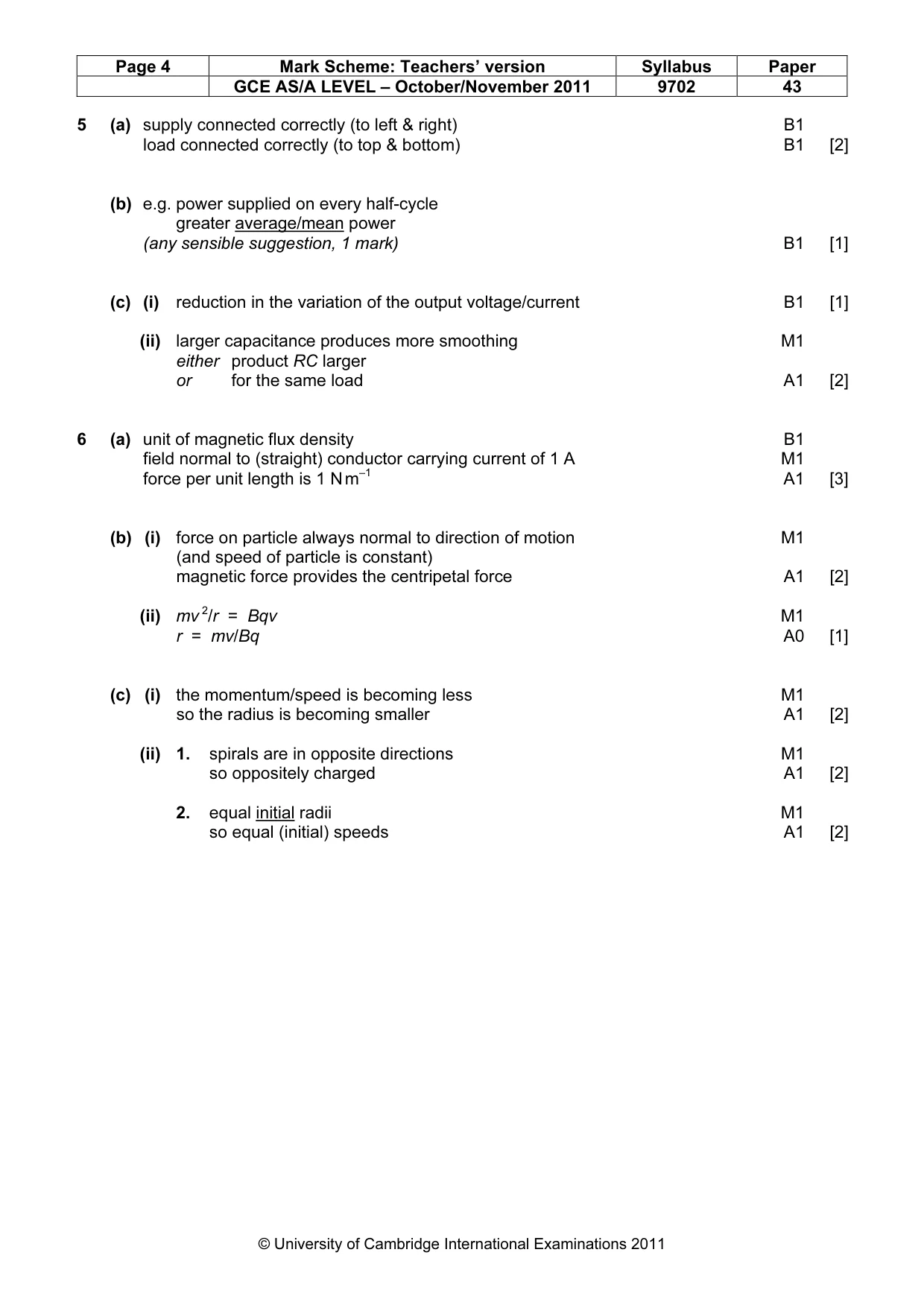
Mark scheme: 5 (a) supply connected correctly (to left & right) B1 load connected correctly (to top & bottom) B1 [2] (b) e.g. power supplied on every half-cycle greater average/mean power (any sensible suggestion, 1 mark) B1 [1] (c) (i) reduction in the variation of the output voltage/current B1 [1] (ii) larger capacitance produces more smoothing M1 either product RC larger or for the same load A1 [2]
Question 6
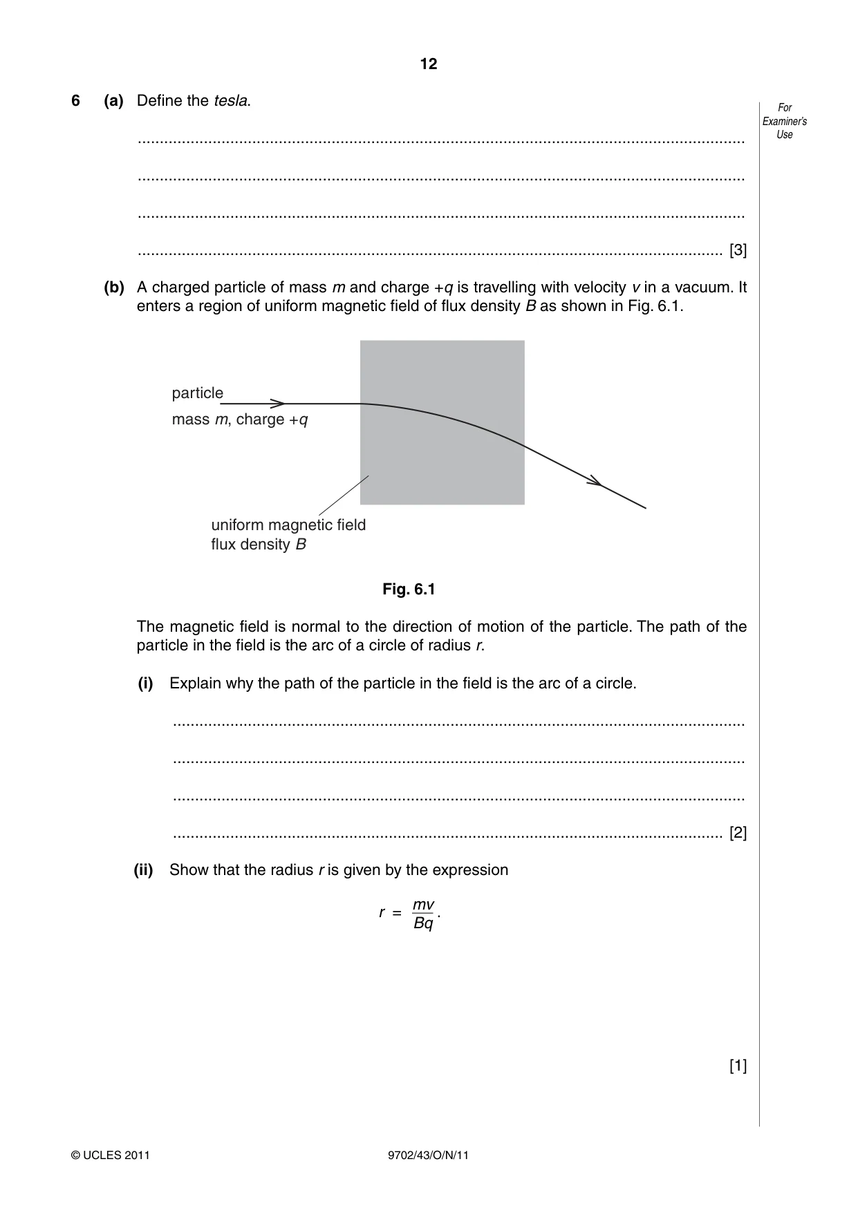
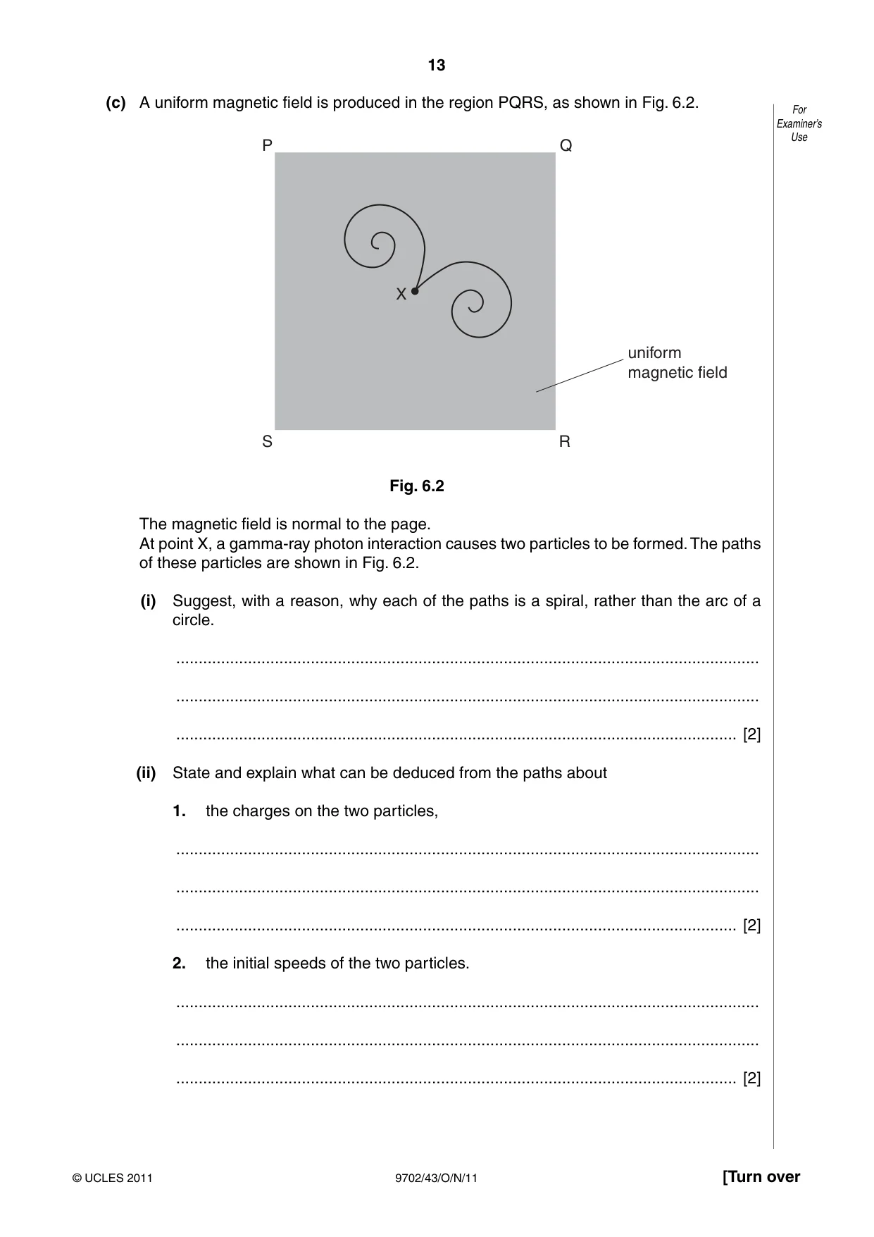
6 (a) Define the tesla. For Examiner’s .......................................................................................................................................... Use .......................................................................................................................................... .......................................................................................................................................... ..................................................................................................................................... [3] (b) A charged particle of mass m and charge +q is travelling with velocity v in a vacuum. It enters a region of uniform magnetic field of flux density B as shown in Fig. 6.1. particle mass m, charge +q uniform magnetic field flux density B Fig. 6.1 The magnetic field is normal to the direction of motion of the particle. The path of the particle in the field is the arc of a circle of radius r. (i) Explain why the path of the particle in the field is the arc of a circle. .................................................................................................................................. .................................................................................................................................. .................................................................................................................................. ............................................................................................................................. [2] (ii) Show that the radius r is given by the expression mv r = . Bq [1] (c) A uniform magnetic field is produced in the region PQRS, as shown in Fig. 6.2. For Examiner’s Use P Q X uniform magnetic field S R Fig. 6.2 The magnetic field is normal to the page. At point X, a gamma-ray photon interaction causes two particles to be formed. The paths of these particles are shown in Fig. 6.2. (i) Suggest, with a reason, why each of the paths is a spiral, rather than the arc of a circle. .................................................................................................................................. .................................................................................................................................. ............................................................................................................................. [2] (ii) State and explain what can be deduced from the paths about 1. the charges on the two particles, .................................................................................................................................. .................................................................................................................................. ............................................................................................................................. [2] 2. the initial speeds of the two particles. .................................................................................................................................. .................................................................................................................................. ............................................................................................................................. [2]
Mark scheme: 6 (a) unit of magnetic flux density B1 field normal to (straight) conductor carrying current of 1 A M1 force per unit length is 1 N m–1 A1 [3] (b) (i) force on particle always normal to direction of motion M1 (and speed of particle is constant) magnetic force provides the centripetal force A1 [2] (ii) mv 2/r = Bqv M1 r = mv/Bq A0 [1] (c) (i) the momentum/speed is becoming less M1 so the radius is becoming smaller A1 [2] (ii) 1. spirals are in opposite directions M1 so oppositely charged A1 [2] 2. equal initial radii M1 so equal (initial) speeds A1 [2] GCE AS/A LEVEL – October/November 2011 9702 43
Q7 · An explanation of the photoelectric effect includes the terms photon energy and work…
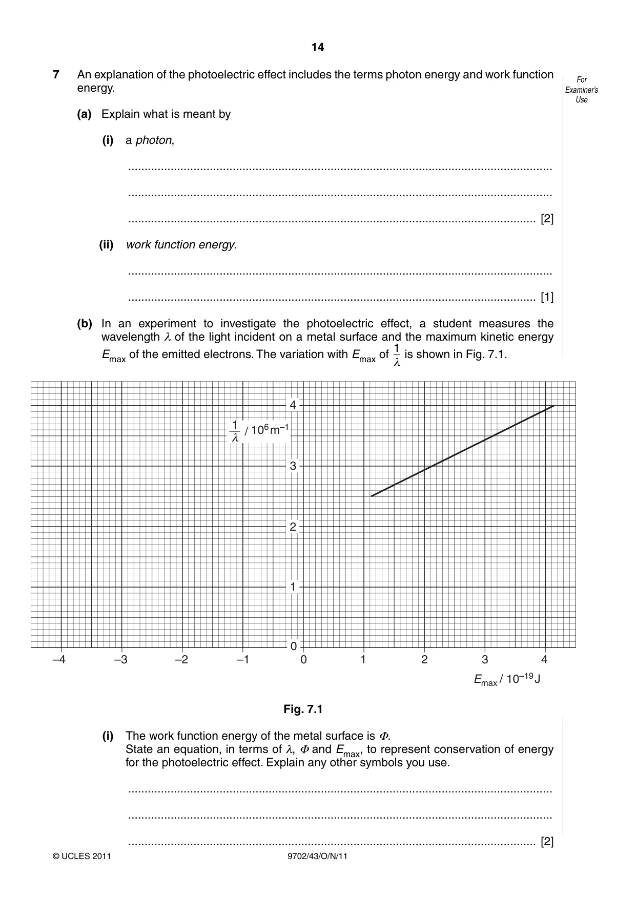
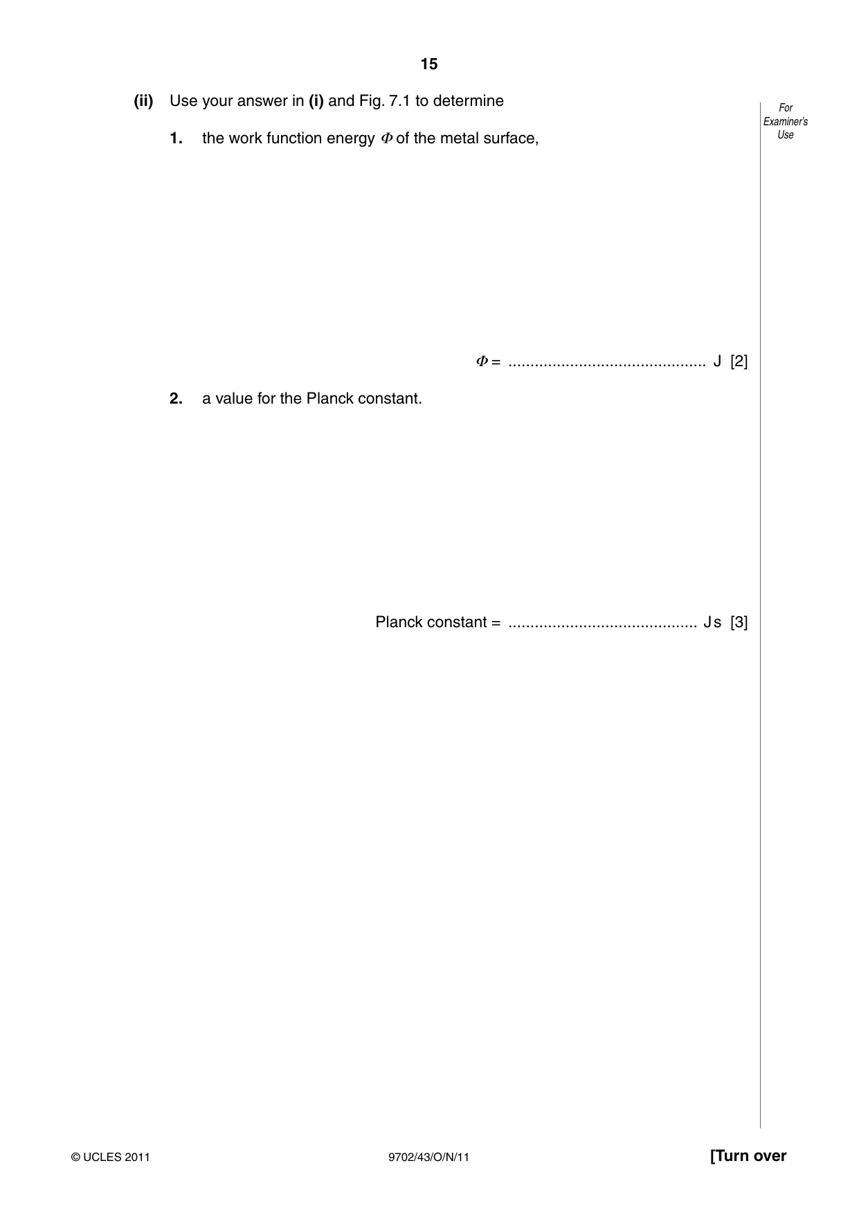
7 An explanation of the photoelectric effect includes the terms photon energy and work function For energy. Examiner’s Use (a) Explain what is meant by (i) a photon, .................................................................................................................................. .................................................................................................................................. ............................................................................................................................. [2] (ii) work function energy. .................................................................................................................................. ............................................................................................................................. [1] (b) In an experiment to investigate the photoelectric effect, a student measures the wavelength λ of the light incident on a metal surface and the maximum kinetic energy 1 Emax of the emitted electrons. The variation with Emax of is shown in Fig. 7.1. λ 4 1 / 106 m–1 λ 3 2 1 0 –4 –3 –2 –1 0 1 2 3 4 Emax / 10–19 J Fig. 7.1 (i) The work function energy of the metal surface is Φ. State an equation, in terms of λ, Φ and Emax, to represent conservation of energy for the photoelectric effect. Explain any other symbols you use. .................................................................................................................................. .................................................................................................................................. ............................................................................................................................. [2] (ii) Use your answer in (i) and Fig. 7.1 to determine For Examiner’s 1. the work function energy Φ of the metal surface, Use Φ = ............................................. J [2] 2. a value for the Planck constant. Planck constant = ........................................... J s [3]
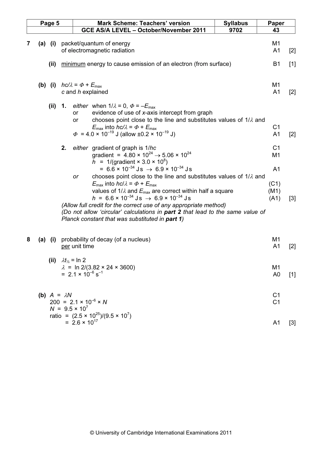
Mark scheme: 7 (a) (i) packet/quantum of energy M1 of electromagnetic radiation A1 [2] (ii) minimum energy to cause emission of an electron (from surface) B1 [1] (b) (i) hc/λ = Φ + Emax M1 c and h explained A1 [2] (ii) 1. either when 1/λ = 0, Φ = –Emax or evidence of use of x-axis intercept from graph or chooses point close to the line and substitutes values of 1/λ and Emax into hc/λ = Φ + Emax C1 Φ = 4.0 × 10⁻¹⁹ J (allow ±0.2 × 10⁻¹⁹ J) A1 [2] 2. either gradient of graph is 1/hc C1 gradient = 4.80 × 1024 → 5.06 × 1024 M1 h = 1/(gradient × 3.0 × 10⁸) = 6.6 × 10⁻³⁴ J s → 6.9 × 10⁻³⁴ J s A1 or chooses point close to the line and substitutes values of 1/λ and Emax into hc/λ = Φ + Emax (C1) values of 1/λ and Emax are correct within half a square (M1) h = 6.6 × 10⁻³⁴ J s → 6.9 × 10⁻³⁴ J s (A1) [3] (Allow full credit for the correct use of any appropriate method) (Do not allow ‘circular’ calculations in part 2 that lead to the same value of Planck constant that was substituted in part 1)
Q8 · Radon-222 is a radioactive element having a half-life of 3.82 days
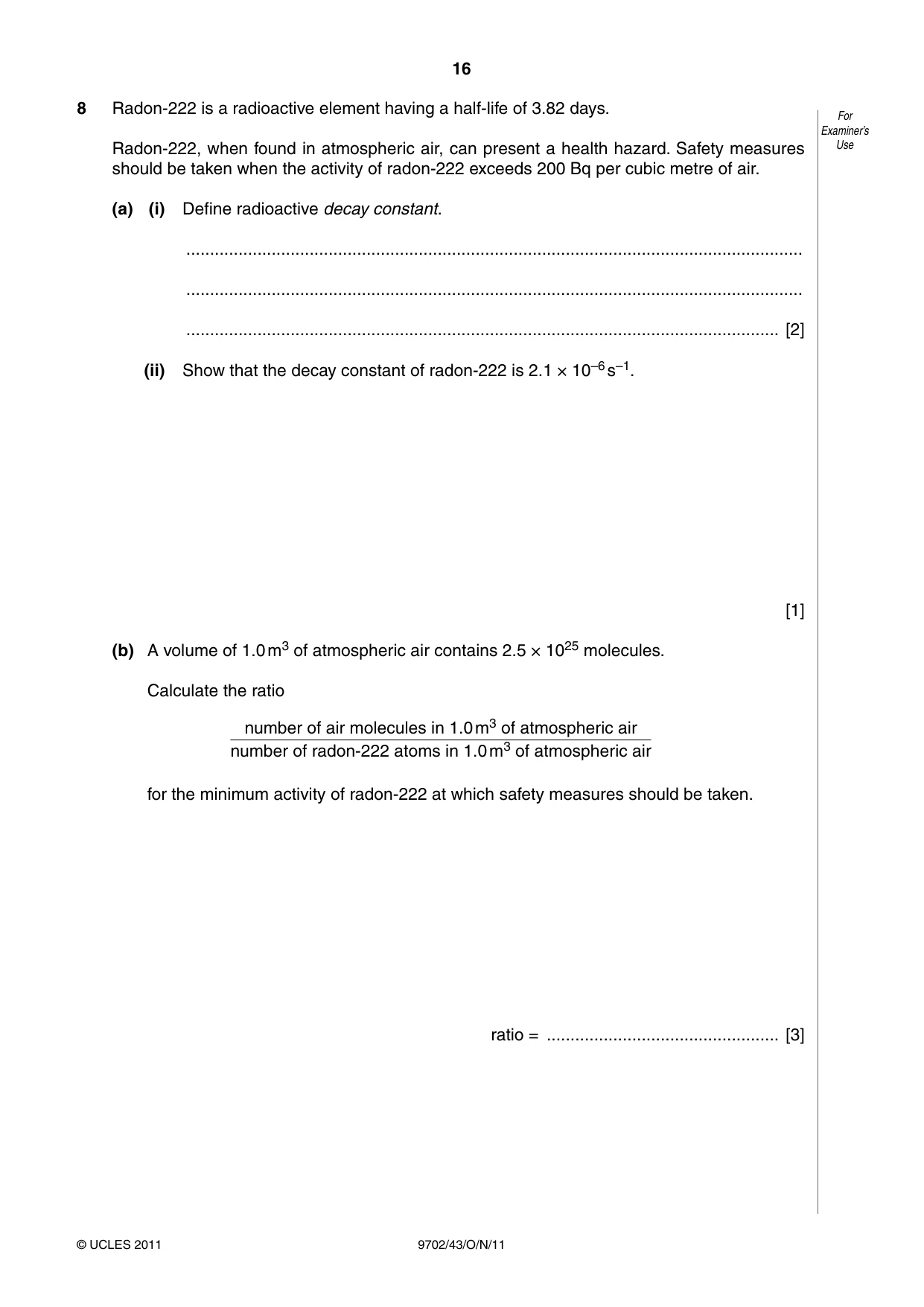
8 Radon-222 is a radioactive element having a half-life of 3.82 days. For Examiner’s Radon-222, when found in atmospheric air, can present a health hazard. Safety measures Use should be taken when the activity of radon-222 exceeds 200 Bq per cubic metre of air. (a) (i) Define radioactive decay constant. .................................................................................................................................. .................................................................................................................................. ............................................................................................................................. [2] (ii) Show that the decay constant of radon-222 is 2.1 × 10⁻⁶ s–1. [1] (b) A volume of 1.0 m3 of atmospheric air contains 2.5 × 1025 molecules. Calculate the ratio number of air molecules in 1.0 m3 of atmospheric air number of radon-222 atoms in 1.0 m3 of atmospheric air for the minimum activity of radon-222 at which safety measures should be taken. ratio = ................................................. [3]
Mark scheme: 8 (a) (i) probability of decay (of a nucleus) M1 per unit time A1 [2] (ii) λt½ = ln 2 λ = ln 2/(3.82 × 24 × 3600) M1 = 2.1 × 10⁻⁶ s–1 A0 [1] (b) A = λN C1 200 = 2.1 × 10⁻⁶ × N C1 N = 9.5 × 10⁷ ratio = (2.5 × 1025)/(9.5 × 107) = 2.6 × 10¹⁷ A1 [3] GCE AS/A LEVEL – October/November 2011 9702 43 Section B
Q9 · The resistance of a light-dependent resistor (LDR) is approximately 500 Ω in daylight
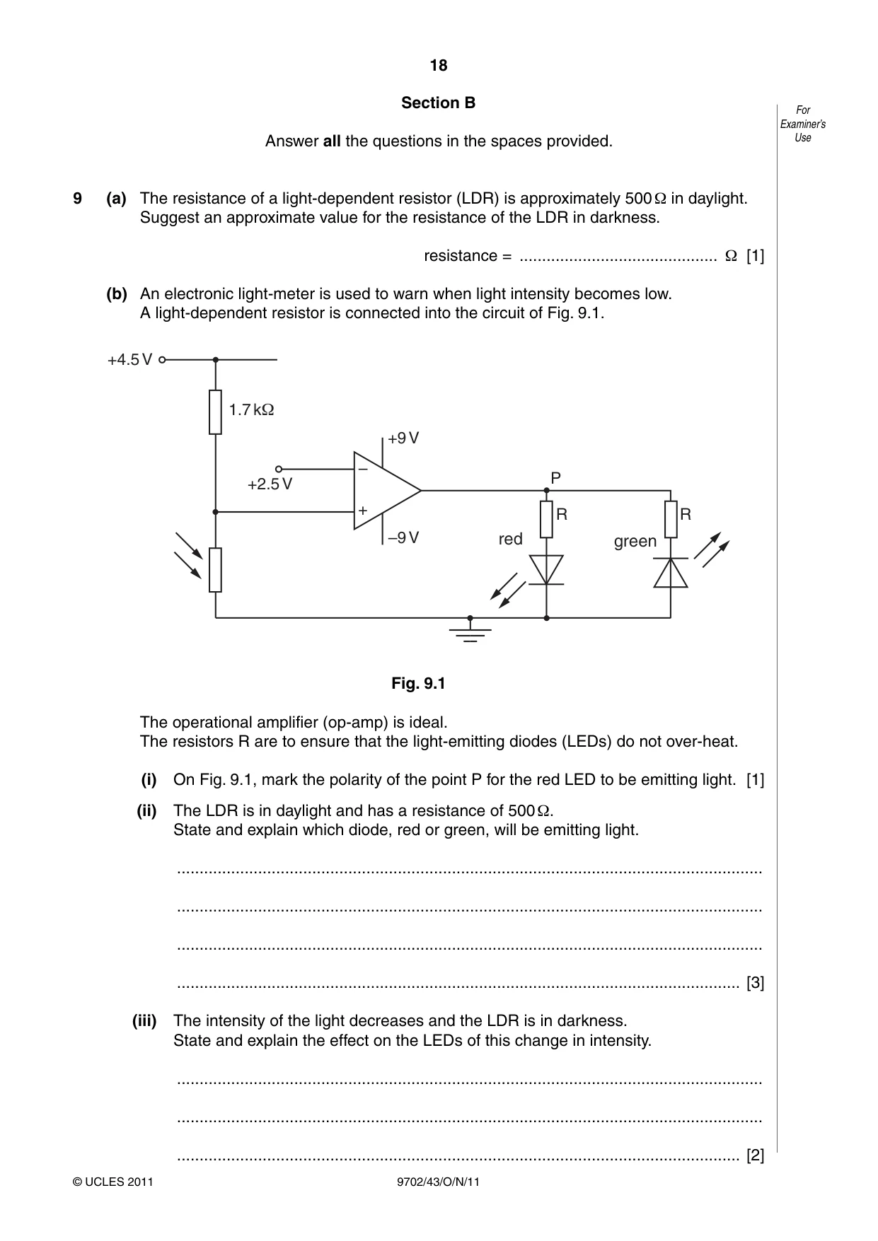
9 (a) The resistance of a light-dependent resistor (LDR) is approximately 500 Ω in daylight. Suggest an approximate value for the resistance of the LDR in darkness. resistance = ............................................ Ω [1] (b) An electronic light-meter is used to warn when light intensity becomes low. A light-dependent resistor is connected into the circuit of Fig. 9.1. +4.5 V 1.7 kΩ +9 V – P +2.5 V + R R –9 V red green Fig. 9.1 The operational amplifier (op-amp) is ideal. The resistors R are to ensure that the light-emitting diodes (LEDs) do not over-heat. (i) On Fig. 9.1, mark the polarity of the point P for the red LED to be emitting light. [1] (ii) The LDR is in daylight and has a resistance of 500 Ω. State and explain which diode, red or green, will be emitting light. .................................................................................................................................. .................................................................................................................................. .................................................................................................................................. ............................................................................................................................. [3] (iii) The intensity of the light decreases and the LDR is in darkness. State and explain the effect on the LEDs of this change in intensity. .................................................................................................................................. .................................................................................................................................. ............................................................................................................................. [2]
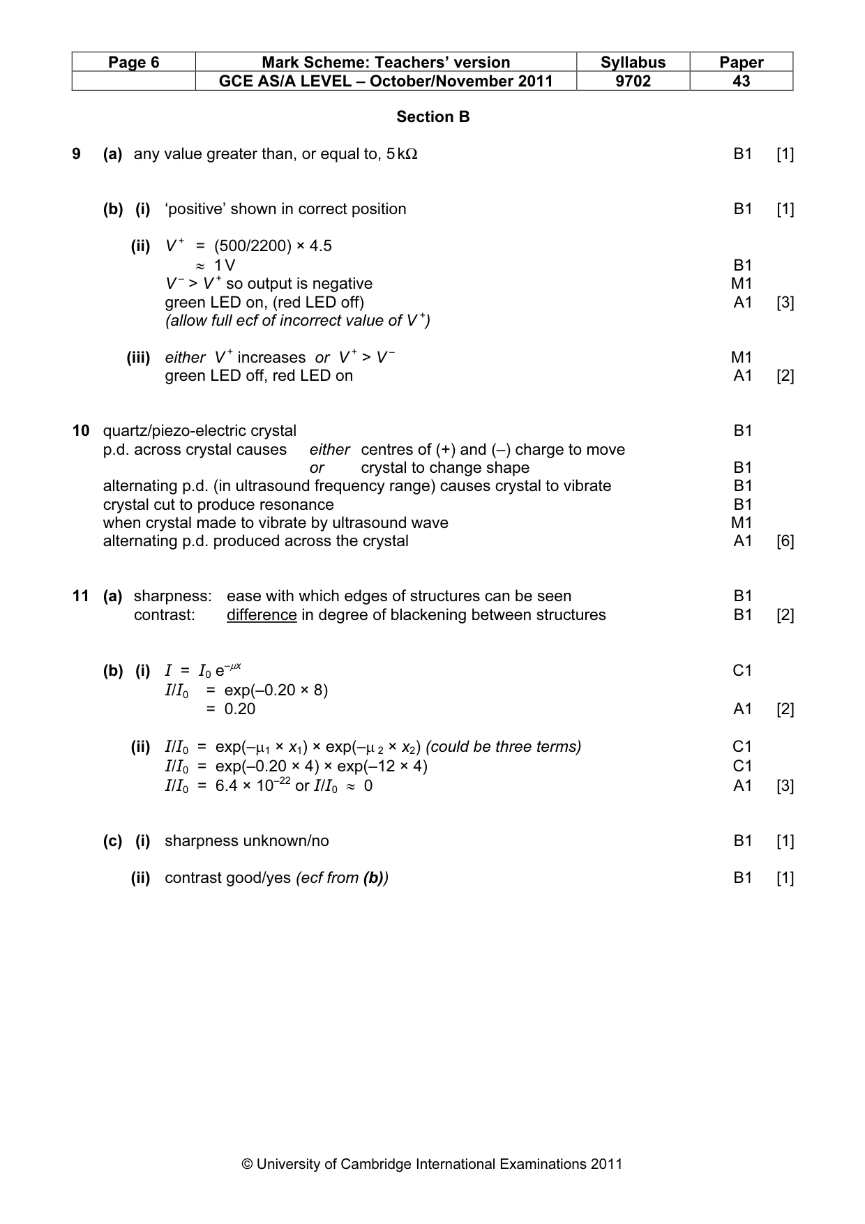
Mark scheme: 9 (a) any value greater than, or equal to, 5 kΩ B1 [1] (b) (i) ‘positive’ shown in correct position B1 [1] (ii) V + = (500/2200) × 4.5 ≈ 1 V B1 V – > V + so output is negative M1 green LED on, (red LED off) A1 [3] (allow full ecf of incorrect value of V +) (iii) either V + increases or V + > V – M1 green LED off, red LED on A1 [2]
Q10 · Explain the principles of the generation and detection of ultrasound waves
10 Explain the principles of the generation and detection of ultrasound waves. For Examiner’s ................................................................................................................................................. Use ................................................................................................................................................. ................................................................................................................................................. ................................................................................................................................................. ................................................................................................................................................. ................................................................................................................................................. ................................................................................................................................................. ................................................................................................................................................. ................................................................................................................................................. ............................................................................................................................................ [6]
Mark scheme: 10 quartz/piezo-electric crystal B1 p.d. across crystal causes either centres of (+) and (–) charge to move or crystal to change shape B1 alternating p.d. (in ultrasound frequency range) causes crystal to vibrate B1 crystal cut to produce resonance B1 when crystal made to vibrate by ultrasound wave M1 alternating p.d. produced across the crystal A1 [6]
Q11 · Distinguish between sharpness and contrast in X-ray imaging
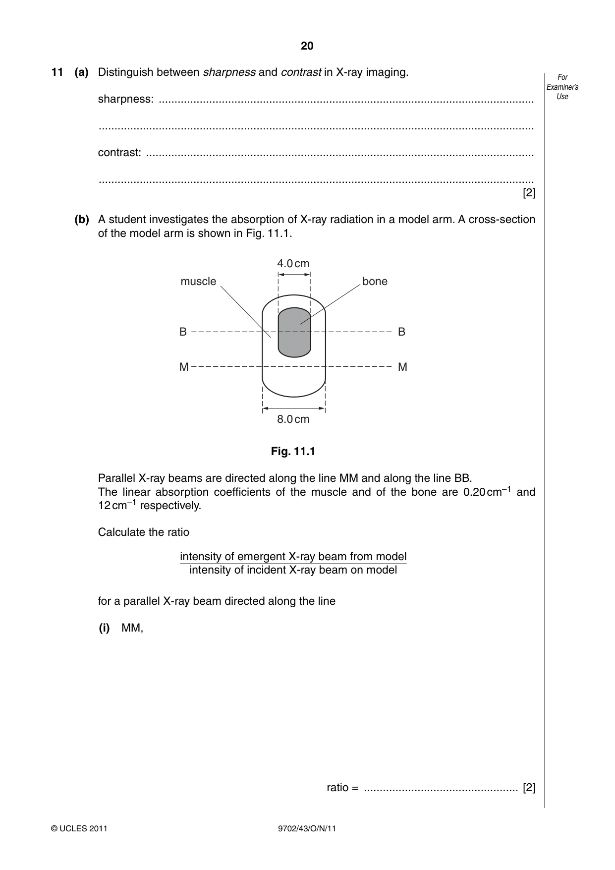
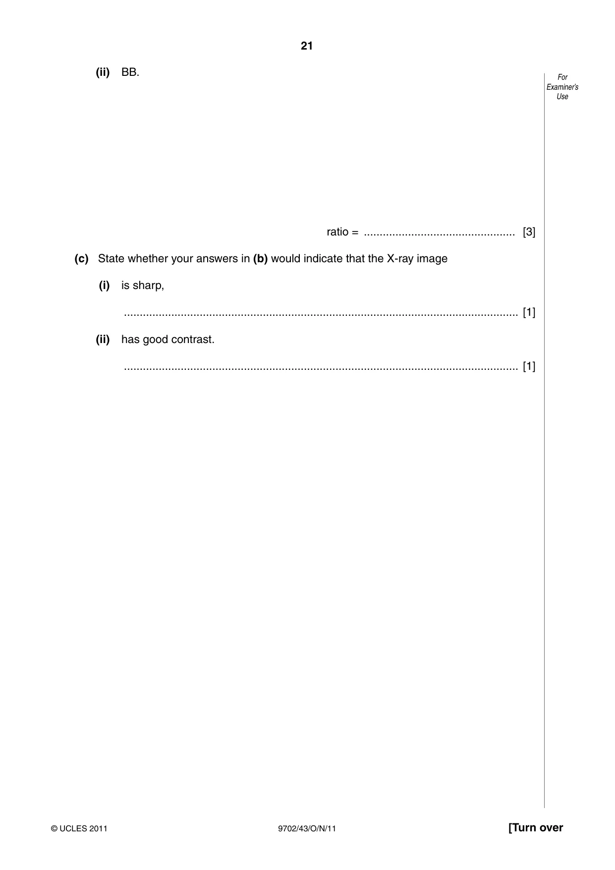
11 (a) Distinguish between sharpness and contrast in X-ray imaging. For Examiner’s sharpness: ....................................................................................................................... Use .......................................................................................................................................... contrast: ........................................................................................................................... .......................................................................................................................................... [2] (b) A student investigates the absorption of X-ray radiation in a model arm. A cross-section of the model arm is shown in Fig. 11.1. 4.0 cm muscle bone B B M M 8.0 cm Fig. 11.1 Parallel X-ray beams are directed along the line MM and along the line BB. The linear absorption coefficients of the muscle and of the bone are 0.20 cm–1 and 12 cm–1 respectively. Calculate the ratio intensity of emergent X-ray beam from model intensity of incident X-ray beam on model for a parallel X-ray beam directed along the line (i) MM, ratio = ................................................. [2] (ii) BB. For Examiner’s Use ratio = ................................................ [3] (c) State whether your answers in (b) would indicate that the X-ray image (i) is sharp, ............................................................................................................................. [1] (ii) has good contrast. ............................................................................................................................. [1]
Mark scheme: 11 (a) sharpness: ease with which edges of structures can be seen B1 contrast: difference in degree of blackening between structures B1 [2] (b) (i) I = I0 e–µx C1 I/I0 = exp(–0.20 × 8) = 0.20 A1 [2] (ii) I/I0 = exp(–µ1 × x1) × exp(–µ 2 × x2) (could be three terms) C1 I/I0 = exp(–0.20 × 4) × exp(–12 × 4) C1 I/I0 = 6.4 × 10⁻²² or I/I0 ≈ 0 A1 [3] (c) (i) sharpness unknown/no B1 [1] (ii) contrast good/yes (ecf from (b)) B1 [1] GCE AS/A LEVEL – October/November 2011 9702 43
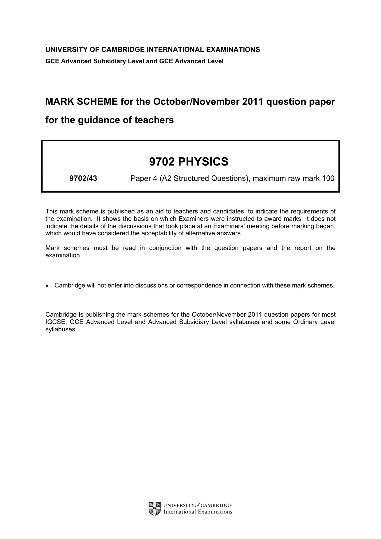
Q12 · In a cellular phone network, a region is divided into a number of cells, each with its…
12 In a cellular phone network, a region is divided into a number of cells, each with its own base For station. Examiner’s Use (a) Suggest and explain two reasons why a region is divided into a number of cells. 1. ..................................................................................................................................... .......................................................................................................................................... .......................................................................................................................................... 2. ..................................................................................................................................... .......................................................................................................................................... .......................................................................................................................................... [4] (b) A passenger in a car is using a mobile phone as the car moves across several cells. Outline how it is ensured that the phone call is continuous. .......................................................................................................................................... .......................................................................................................................................... .......................................................................................................................................... .......................................................................................................................................... ..................................................................................................................................... [4]
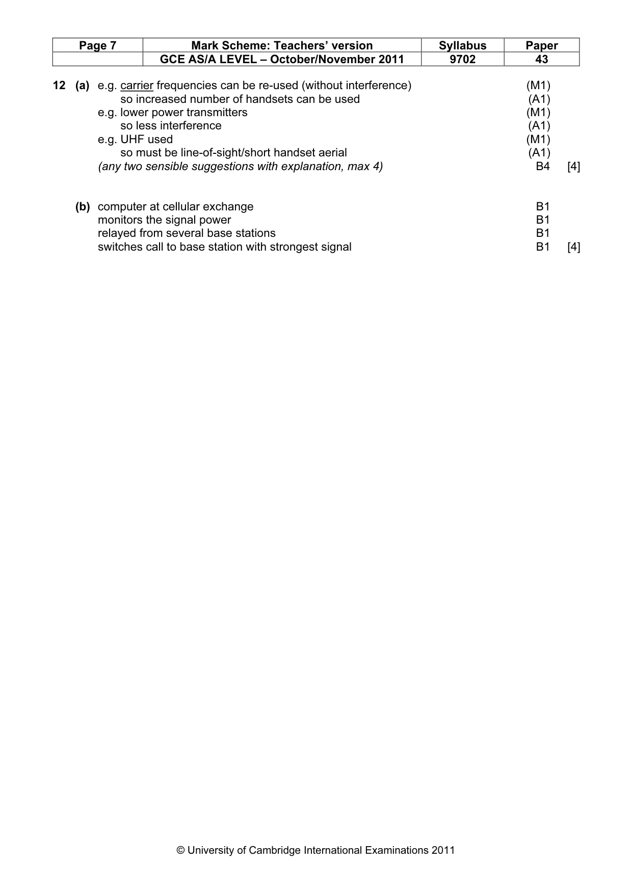
Mark scheme: 12 (a) e.g. carrier frequencies can be re-used (without interference) (M1) so increased number of handsets can be used (A1) e.g. lower power transmitters (M1) so less interference (A1) e.g. UHF used (M1) so must be line-of-sight/short handset aerial (A1) (any two sensible suggestions with explanation, max 4) B4 [4] (b) computer at cellular exchange B1 monitors the signal power B1 relayed from several base stations B1 switches call to base station with strongest signal B1 [4]
What was in this paper
The subtopics covered by these 12 questions, and how many questions each got. Open one in a new tab to see every Cambridge question on it.
What you needed in this session
Cambridge’s own grade thresholds for 2011 Oct/Nov, Paper 4 · Variant 3. A higher threshold means an easier paper — the bar moves with how the cohort did.