Cambridge A Level Physics 9702 — 2010 Oct/Nov Paper 4 · Variant 2
9702/42/O/N/10 · 12 questions · 100 marks · ≈113 min
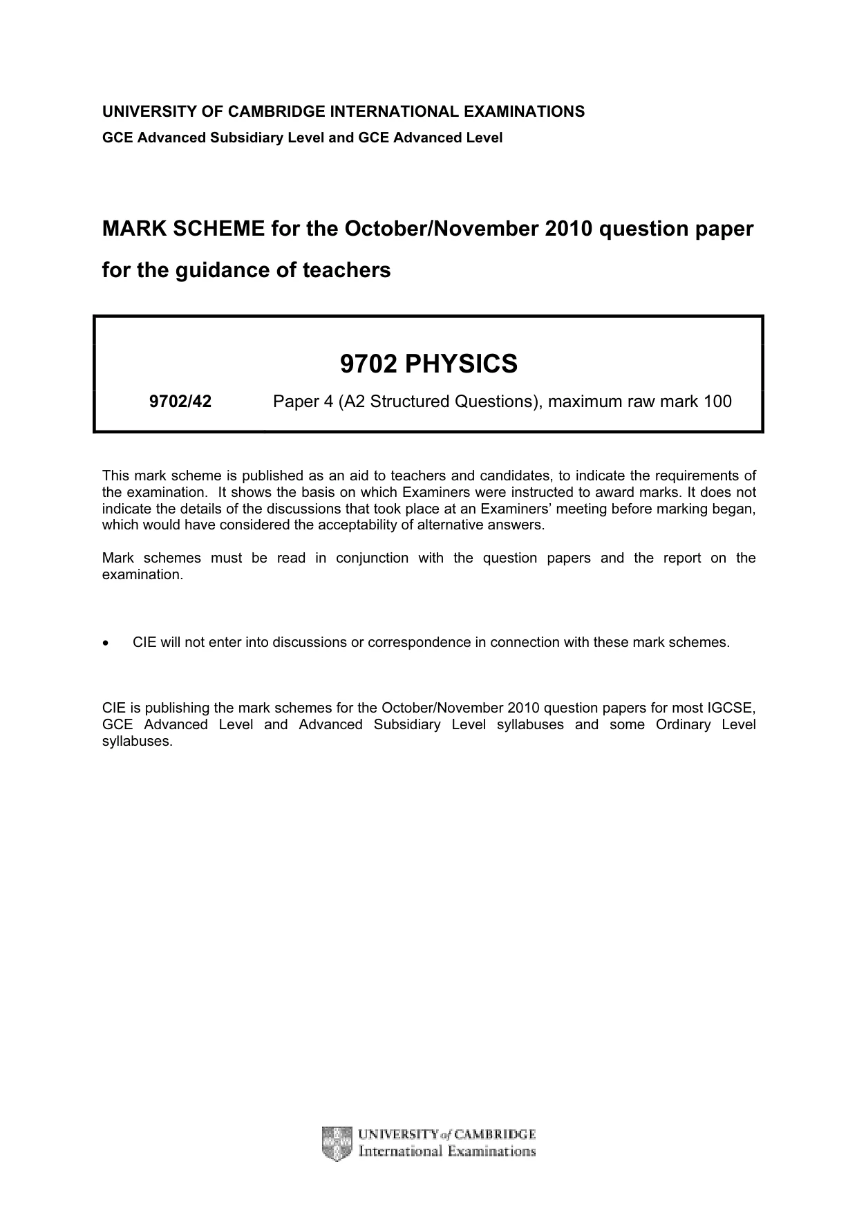
The question paper and its mark scheme, free to read here and free to download. This is Cambridge’s own paper, exactly as it was sat.
Question paper24 pages
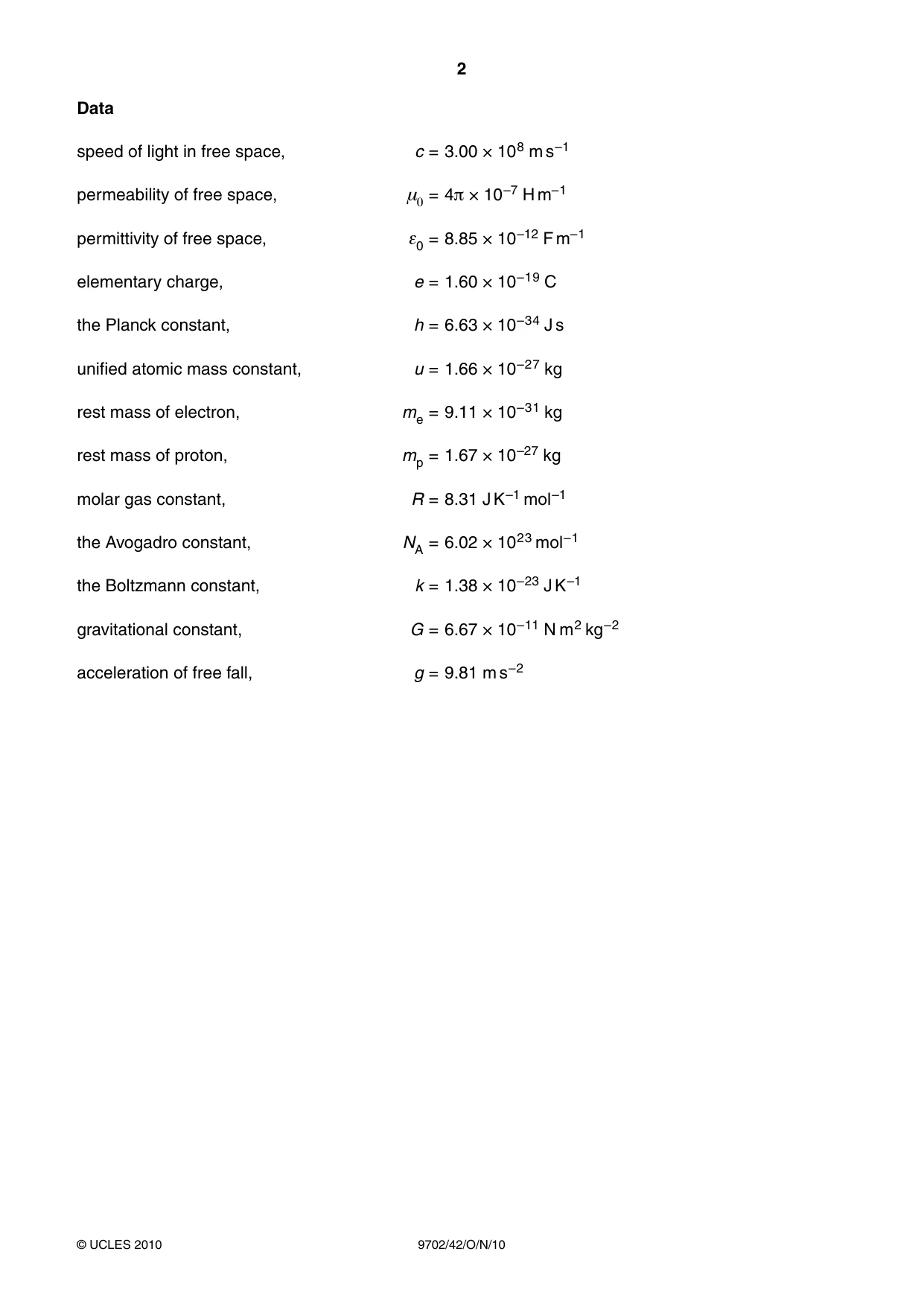
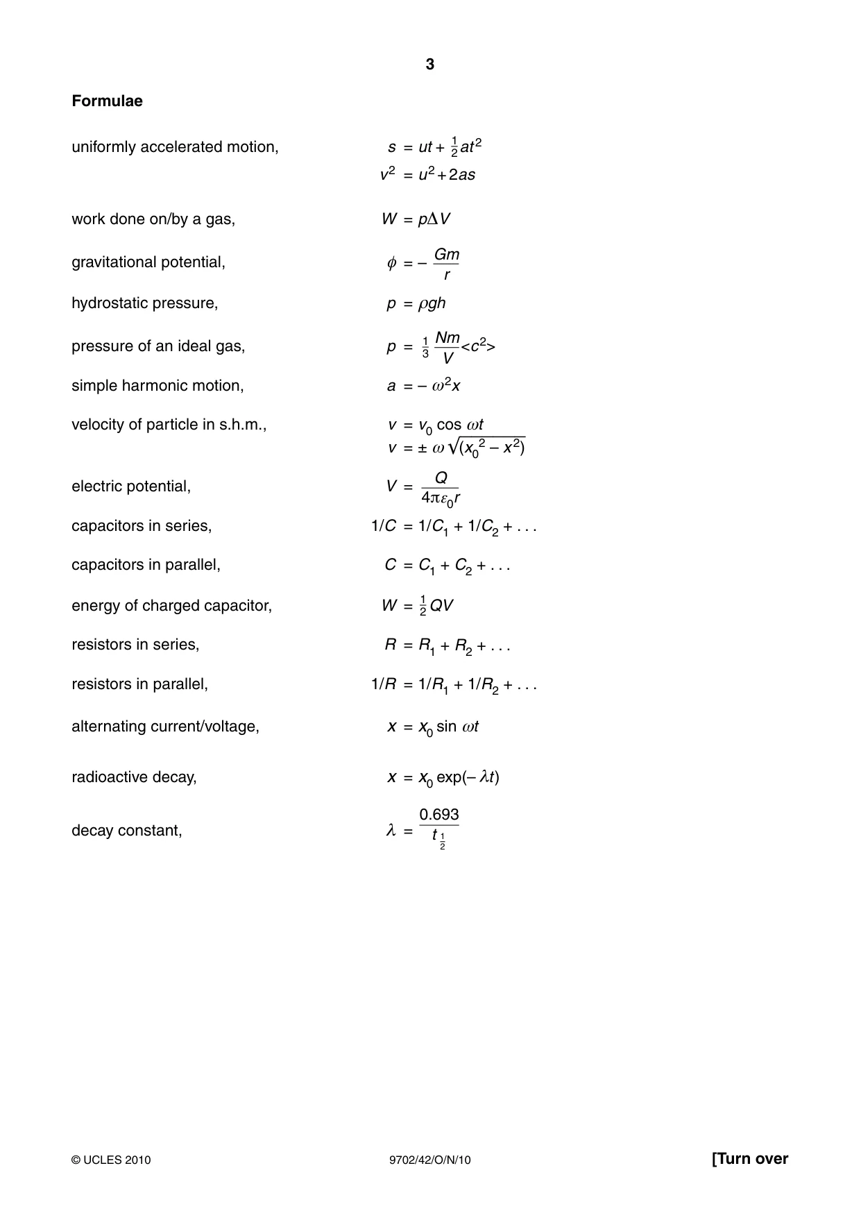
Mark scheme6 pages
Answers below. Sit the paper first if you are practising.
Questions as text
Q1 · Define gravitational field strength
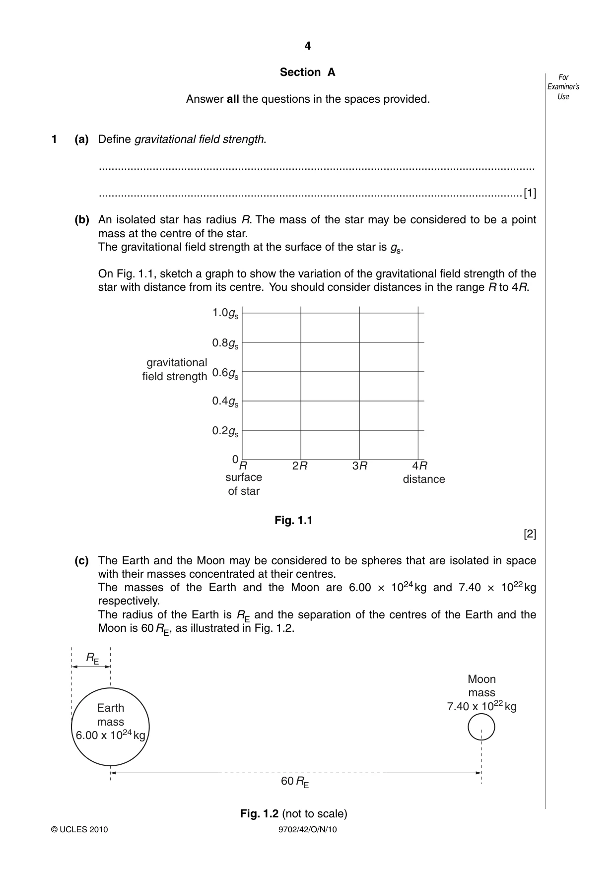
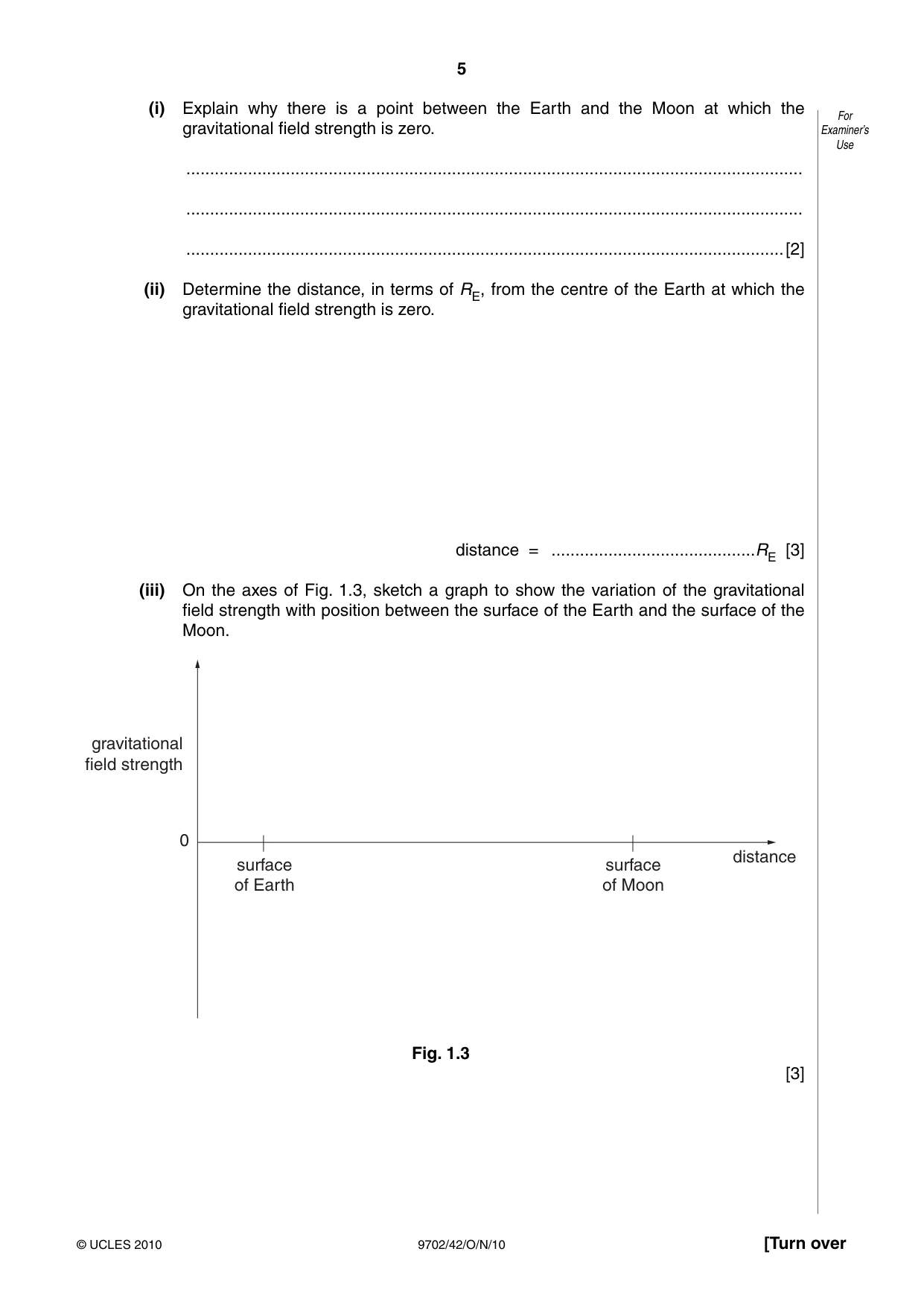
1 (a) Define gravitational field strength. .......................................................................................................................................... ......................................................................................................................................[1] (b) An isolated star has radius R. The mass of the star may be considered to be a point mass at the centre of the star. The gravitational field strength at the surface of the star is gs. On Fig. 1.1, sketch a graph to show the variation of the gravitational field strength of the star with distance from its centre. You should consider distances in the range R to 4R. 1.0gs 0.8gs gravitational field strength 0.6gs 0.4gs 0.2gs 0R 2R 3R 4R surface distance of star Fig. 1.1 [2] (c) The Earth and the Moon may be considered to be spheres that are isolated in space with their masses concentrated at their centres. The masses of the Earth and the Moon are 6.00 × 1024 kg and 7.40 × 10²² kg respectively. The radius of the Earth is RE and the separation of the centres of the Earth and the Moon is 60 RE, as illustrated in Fig. 1.2. RE Moon mass Earth 7.40 x 10²² kg mass 6.00 x 1024 kg 60 RE Fig. 1.2 (not to scale) (i) Explain why there is a point between the Earth and the Moon at which the For gravitational field strength is zero. Examiner’s Use .................................................................................................................................. .................................................................................................................................. ..............................................................................................................................[2] (ii) Determine the distance, in terms of RE, from the centre of the Earth at which the gravitational field strength is zero. distance = ...........................................RE [3] (iii) On the axes of Fig. 1.3, sketch a graph to show the variation of the gravitational field strength with position between the surface of the Earth and the surface of the Moon. gravitational field strength 0 distance surface surface of Earth of Moon Fig. 1.3 [3]
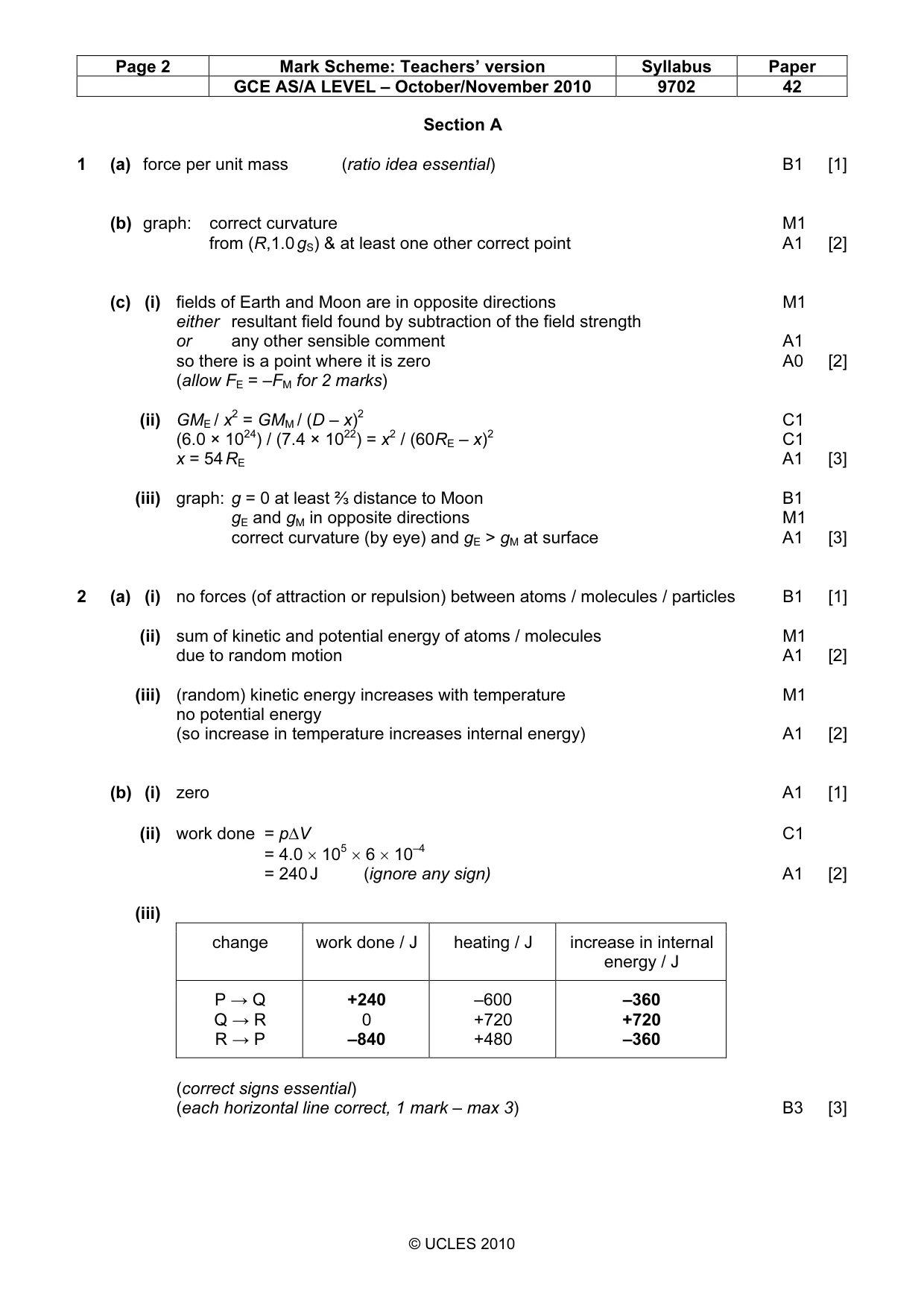
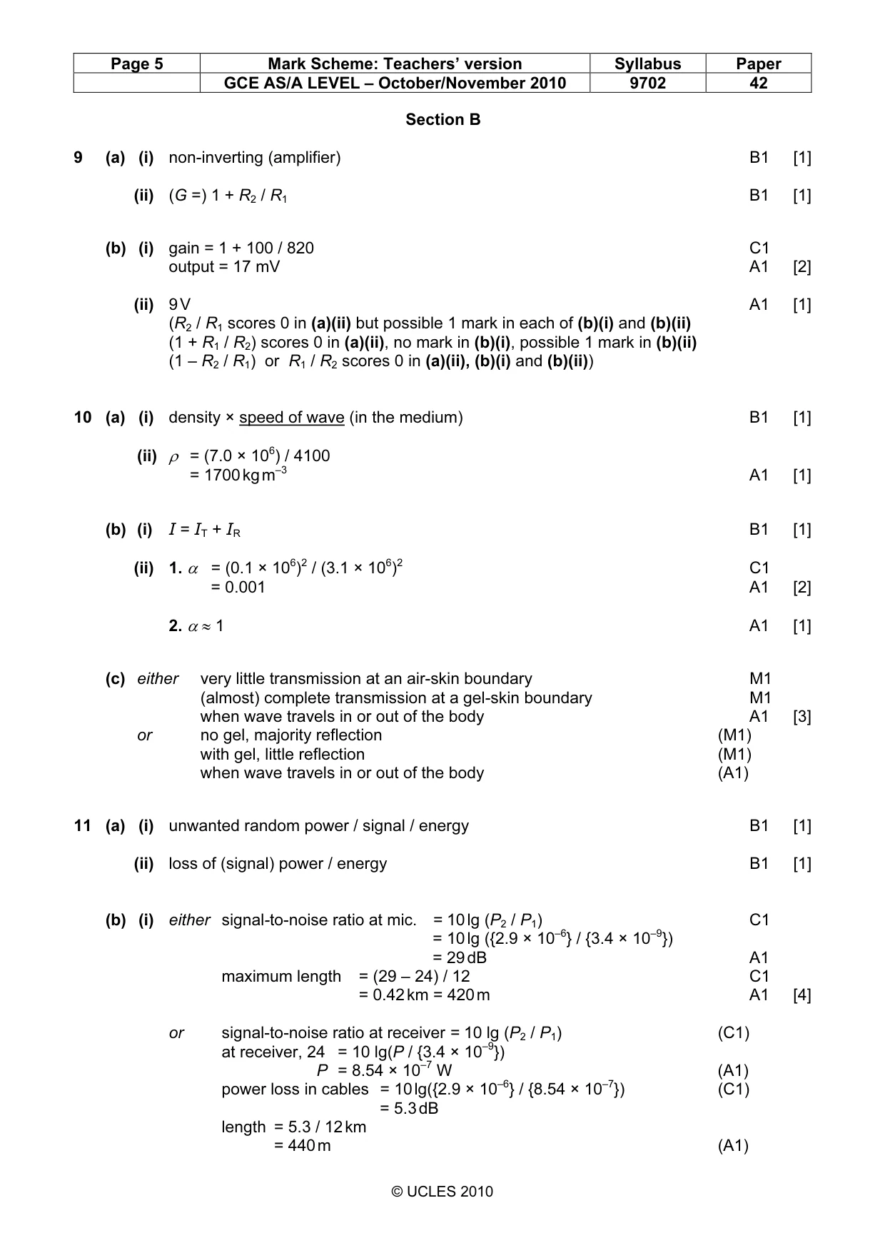
Mark scheme: 1 (a) force per unit mass (ratio idea essential) B1 [1] (b) graph: correct curvature M1 from (R,1.0 gS) & at least one other correct point A1 [2] (c) (i) fields of Earth and Moon are in opposite directions M1 either resultant field found by subtraction of the field strength or any other sensible comment A1 so there is a point where it is zero A0 [2] (allow FE = –FM for 2 marks) (ii) GME / x2 = GMM / (D – x)2 C1 (6.0 × 1024) / (7.4 × 10²²) = x2 / (60RE – x)2 C1 x = 54 RE A1 [3] (iii) graph: g = 0 at least ⅔ distance to Moon B1 gE and gM in opposite directions M1 correct curvature (by eye) and gE > gM at surface A1 [3]
Q2 · State the basic assumption of the kinetic theory of gases that leads to the conclusion…
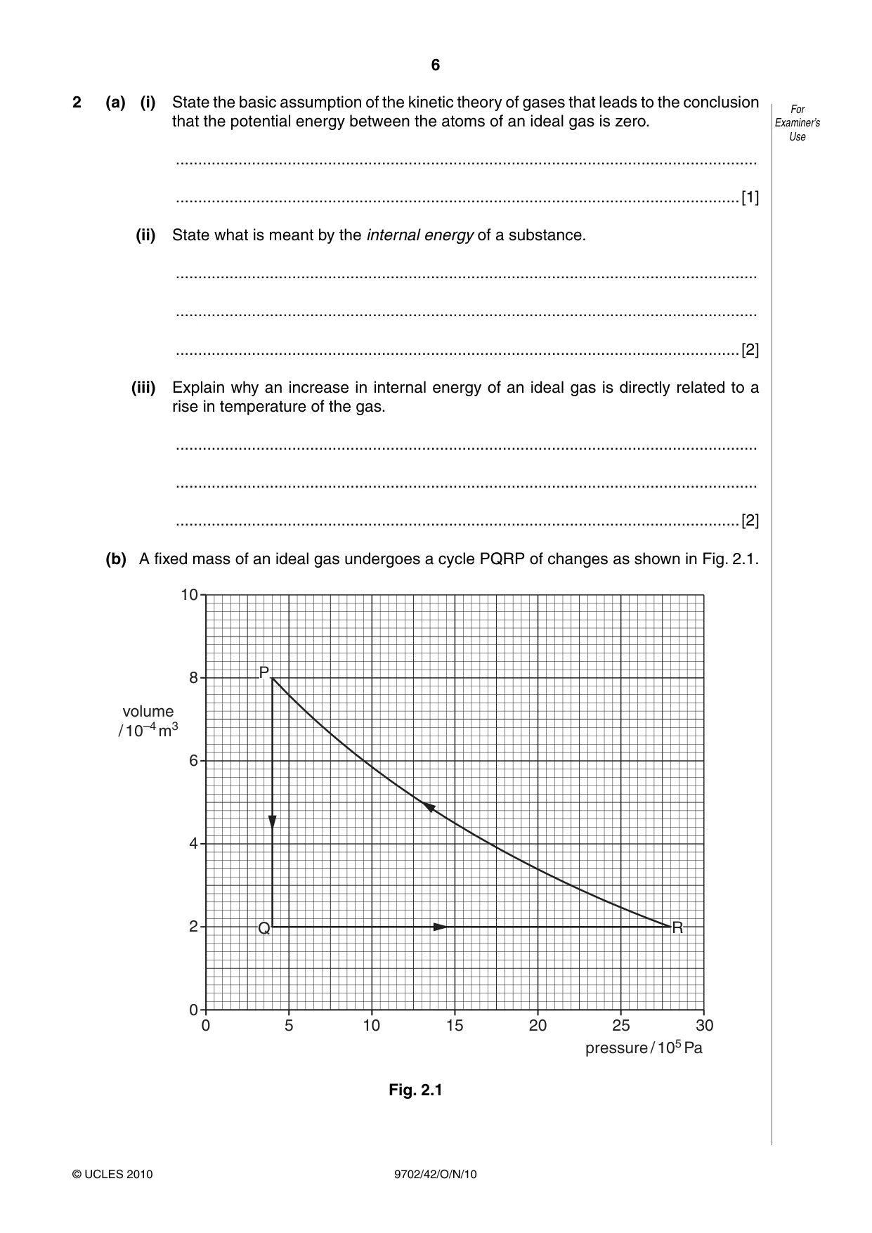
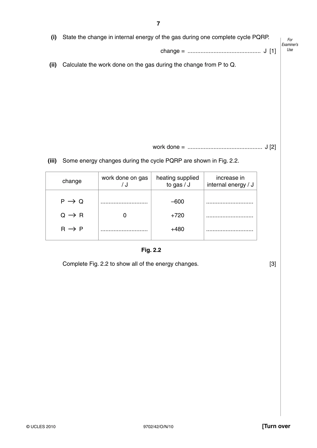
2 (a) (i) State the basic assumption of the kinetic theory of gases that leads to the conclusion For that the potential energy between the atoms of an ideal gas is zero. Examiner’s Use .................................................................................................................................. ..............................................................................................................................[1] (ii) State what is meant by the internal energy of a substance. .................................................................................................................................. .................................................................................................................................. ..............................................................................................................................[2] (iii) Explain why an increase in internal energy of an ideal gas is directly related to a rise in temperature of the gas. .................................................................................................................................. .................................................................................................................................. ..............................................................................................................................[2] (b) A fixed mass of an ideal gas undergoes a cycle PQRP of changes as shown in Fig. 2.1. 10 P 8 volume / 10–4 m3 6 4 2 Q R 0 0 5 10 15 20 25 30 pressure / 105 Pa Fig. 2.1 (i) State the change in internal energy of the gas during one complete cycle PQRP. For Examiner’s change = ............................................. J [1] Use (ii) Calculate the work done on the gas during the change from P to Q. work done = .............................................. J [2] (iii) Some energy changes during the cycle PQRP are shown in Fig. 2.2. work done on gas heating supplied increase in change / J to gas / J internal energy / J P Q ............................. –600 ............................. Q R 0 +720 ............................. R P ............................. +480 ............................. Fig. 2.2 Complete Fig. 2.2 to show all of the energy changes. [3]
Mark scheme: 2 (a) (i) no forces (of attraction or repulsion) between atoms / molecules / particles B1 [1] (ii) sum of kinetic and potential energy of atoms / molecules M1 due to random motion A1 [2] (iii) (random) kinetic energy increases with temperature M1 no potential energy (so increase in temperature increases internal energy) A1 [2] (b) (i) zero A1 [1] (ii) work done = p∆V C1 = 4.0 × 105 × 6 × 10–4 = 240 J (ignore any sign) A1 [2] (iii) change work done / J heating / J increase in internal energy / J P → Q +240 –600 –360 Q → R 0 +720 +720 R → P –840 +480 –360 (correct signs essential) (each horizontal line correct, 1 mark – max 3) B3 [3] GCE AS/A LEVEL – October/November 2010 9702 42
Q3 · A student sets up the apparatus illustrated in Fig
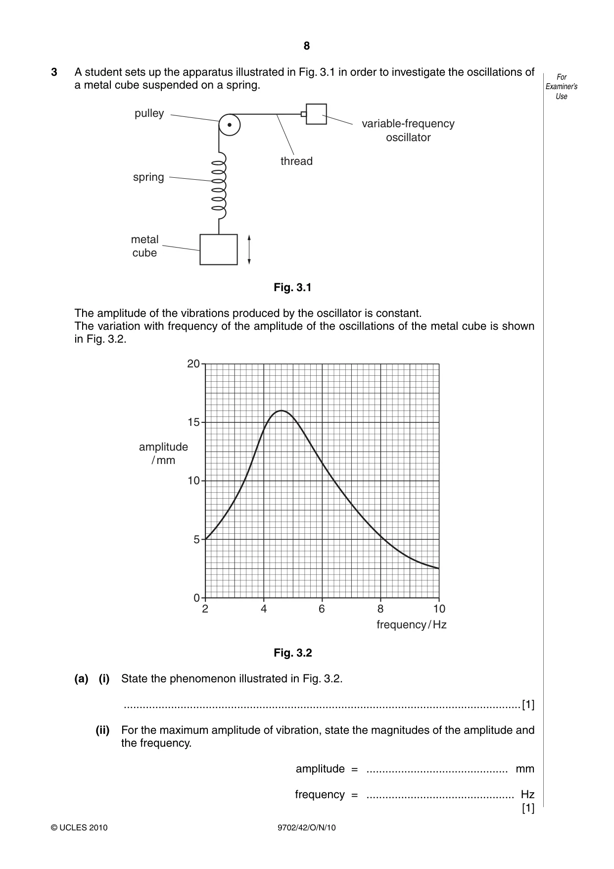
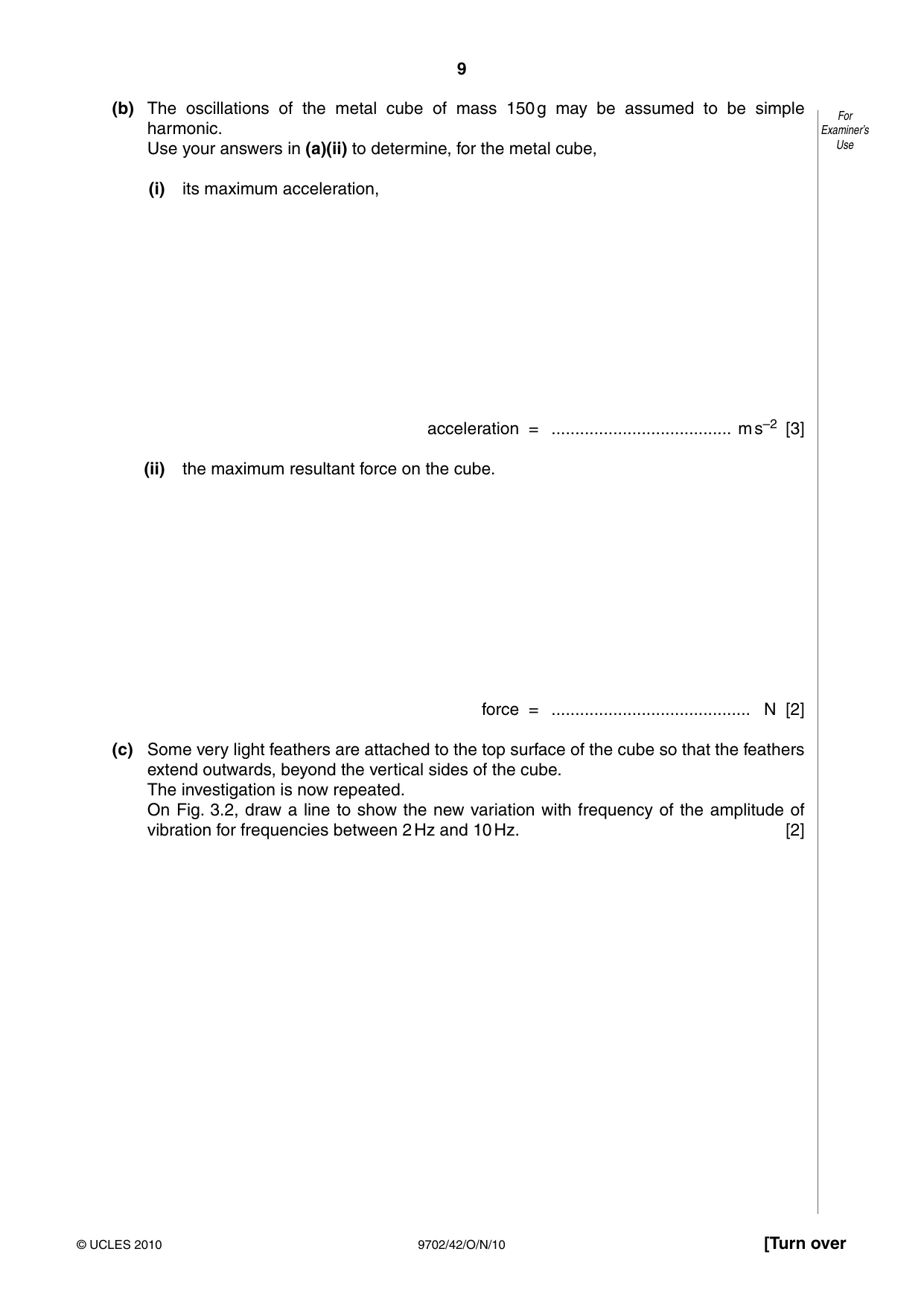
3 A student sets up the apparatus illustrated in Fig. 3.1 in order to investigate the oscillations of For a metal cube suspended on a spring. Examiner’s Use pulley variable-frequency oscillator thread spring metal cube Fig. 3.1 The amplitude of the vibrations produced by the oscillator is constant. The variation with frequency of the amplitude of the oscillations of the metal cube is shown in Fig. 3.2. 20 15 amplitude / mm 10 5 0 2 4 6 8 10 frequency / Hz Fig. 3.2 (a) (i) State the phenomenon illustrated in Fig. 3.2. ..............................................................................................................................[1] (ii) For the maximum amplitude of vibration, state the magnitudes of the amplitude and the frequency. amplitude = ............................................. mm frequency = ............................................... Hz [1] (b) The oscillations of the metal cube of mass 150 g may be assumed to be simple For harmonic. Examiner’s Use your answers in (a)(ii) to determine, for the metal cube, Use (i) its maximum acceleration, acceleration = ...................................... m s–2 [3] (ii) the maximum resultant force on the cube. force = .......................................... N [2] (c) Some very light feathers are attached to the top surface of the cube so that the feathers extend outwards, beyond the vertical sides of the cube. The investigation is now repeated. On Fig. 3.2, draw a line to show the new variation with frequency of the amplitude of vibration for frequencies between 2 Hz and 10 Hz. [2]
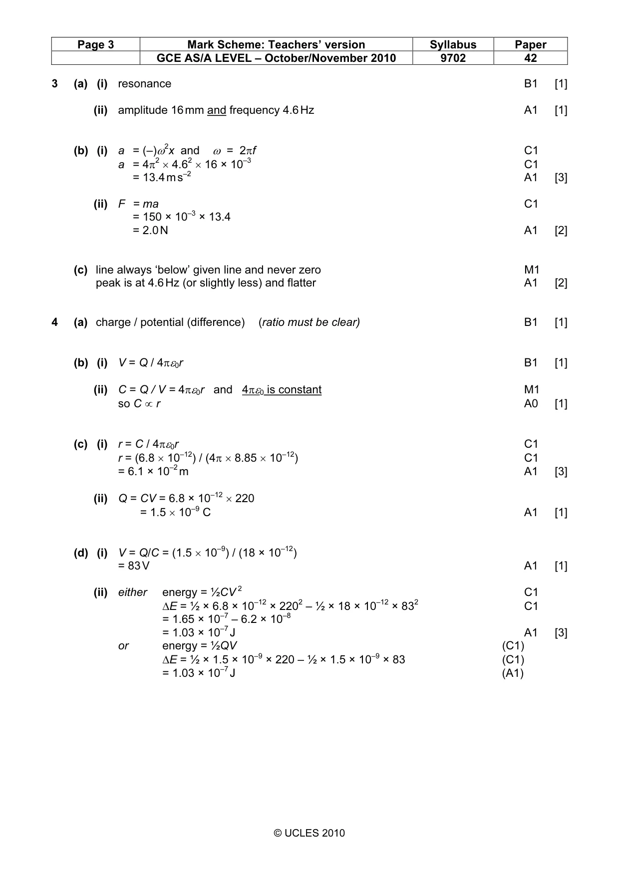
Mark scheme: 3 (a) (i) resonance B1 [1] (ii) amplitude 16 mm and frequency 4.6 Hz A1 [1] (b) (i) a = (–)ω2x and ω = 2πf C1 a = 4π2 × 4.62 × 16 × 10–3 C1 = 13.4 m s–2 A1 [3] (ii) F = ma C1 = 150 × 10–3 × 13.4 = 2.0 N A1 [2] (c) line always ‘below’ given line and never zero M1 peak is at 4.6 Hz (or slightly less) and flatter A1 [2]
Question 4
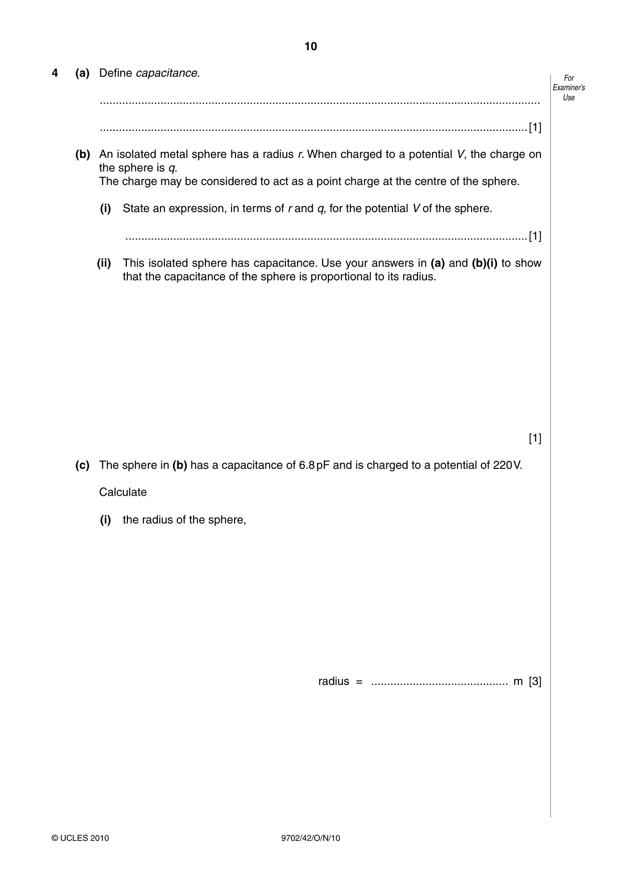
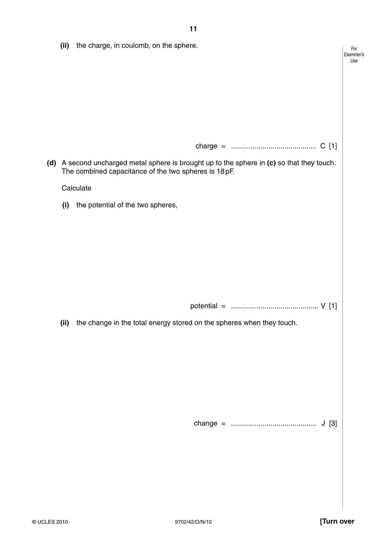
4 (a) Define capacitance. For Examiner’s .......................................................................................................................................... Use ......................................................................................................................................[1] (b) An isolated metal sphere has a radius r. When charged to a potential V, the charge on the sphere is q. The charge may be considered to act as a point charge at the centre of the sphere. (i) State an expression, in terms of r and q, for the potential V of the sphere. ..............................................................................................................................[1] (ii) This isolated sphere has capacitance. Use your answers in (a) and (b)(i) to show that the capacitance of the sphere is proportional to its radius. [1] (c) The sphere in (b) has a capacitance of 6.8 pF and is charged to a potential of 220 V. Calculate (i) the radius of the sphere, radius = ........................................... m [3] (ii) the charge, in coulomb, on the sphere. For Examiner’s Use charge = ........................................... C [1] (d) A second uncharged metal sphere is brought up to the sphere in (c) so that they touch. The combined capacitance of the two spheres is 18 pF. Calculate (i) the potential of the two spheres, potential = ............................................ V [1] (ii) the change in the total energy stored on the spheres when they touch. change = ........................................... J [3]
Mark scheme: 4 (a) charge / potential (difference) (ratio must be clear) B1 [1] (b) (i) V = Q / 4πε0r B1 [1] (ii) C = Q / V = 4πε0r and 4πε0 is constant M1 so C ∝ r A0 [1] (c) (i) r = C / 4πε0r C1 r = (6.8 × 10⁻¹²) / (4π × 8.85 × 10–12) C1 = 6.1 × 10⁻² m A1 [3] (ii) Q = CV = 6.8 × 10–12 × 220 = 1.5 × 10⁻⁹ C A1 [1] (d) (i) V = Q/C = (1.5 × 10⁻⁹) / (18 × 10–12) = 83 V A1 [1] (ii) either energy = ½CV 2 C1 ∆E = ½ × 6.8 × 10–12 × 2202 – ½ × 18 × 10–12 × 832 C1 = 1.65 × 10⁻⁷ – 6.2 × 10–8 = 1.03 × 10⁻⁷ J A1 [3] or energy = ½QV (C1) ∆E = ½ × 1.5 × 10–9 × 220 – ½ × 1.5 × 10–9 × 83 (C1) = 1.03 × 10⁻⁷ J (A1) GCE AS/A LEVEL – October/November 2010 9702 42
Q5 · Positive ions are travelling through a vacuum in a narrow beam
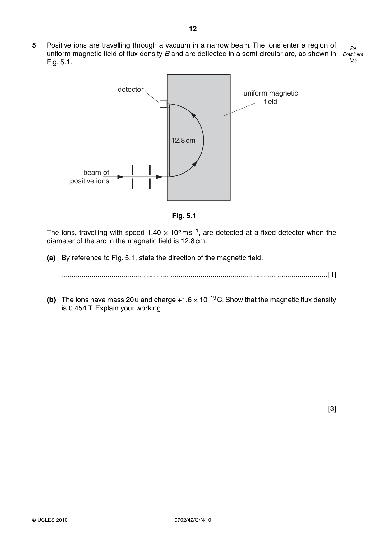
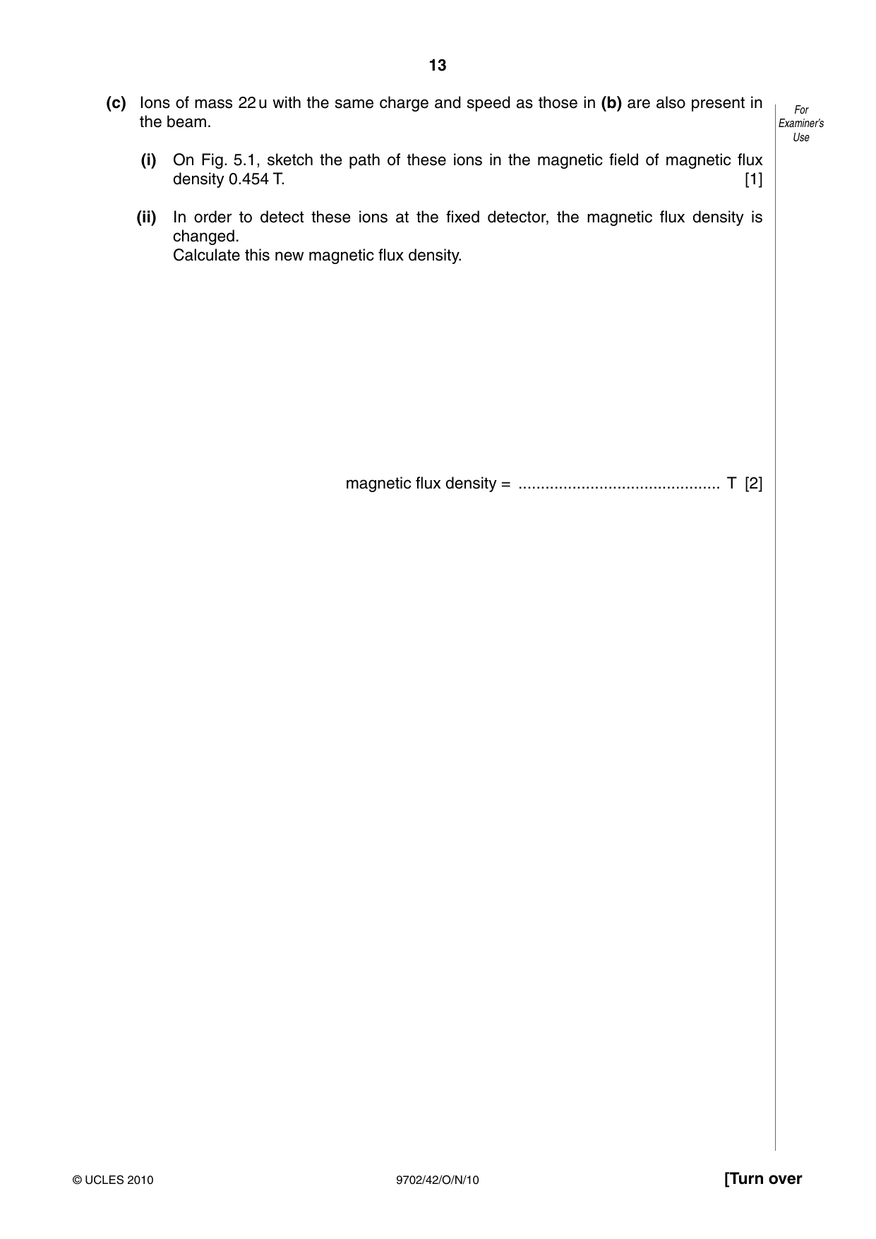
5 Positive ions are travelling through a vacuum in a narrow beam. The ions enter a region of For uniform magnetic field of flux density B and are deflected in a semi-circular arc, as shown in Examiner’s Fig. 5.1. Use detector uniform magnetic field 12.8 cm beam of positive ions Fig. 5.1 The ions, travelling with speed 1.40 × 10⁵ m s–1, are detected at a fixed detector when the diameter of the arc in the magnetic field is 12.8 cm. (a) By reference to Fig. 5.1, state the direction of the magnetic field. ......................................................................................................................................[1] (b) The ions have mass 20 u and charge +1.6 × 10⁻¹⁹ C. Show that the magnetic flux density is 0.454 T. Explain your working. [3] (c) Ions of mass 22 u with the same charge and speed as those in (b) are also present in For the beam. Examiner’s Use (i) On Fig. 5.1, sketch the path of these ions in the magnetic field of magnetic flux density 0.454 T. [1] (ii) In order to detect these ions at the fixed detector, the magnetic flux density is changed. Calculate this new magnetic flux density. magnetic flux density = ............................................. T [2]
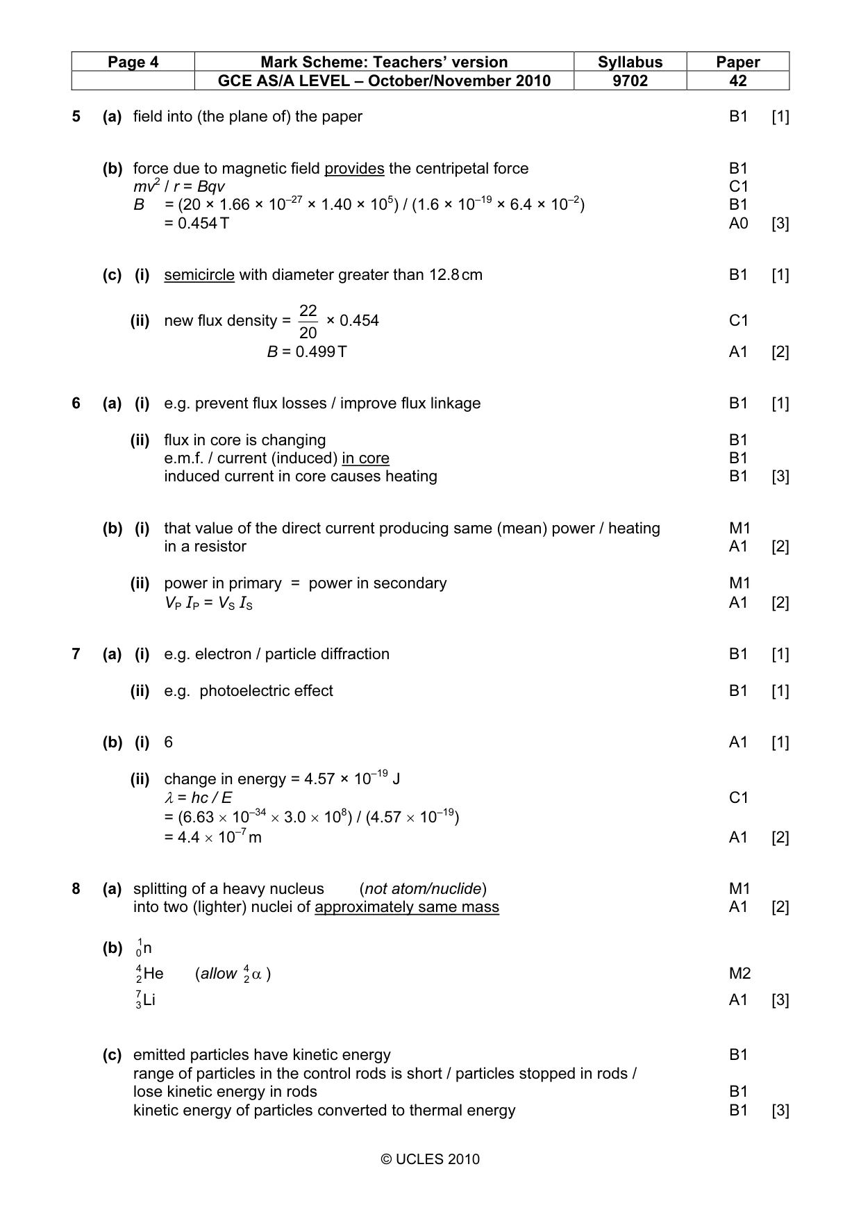
Mark scheme: 5 (a) field into (the plane of) the paper B1 [1] (b) force due to magnetic field provides the centripetal force B1 mv2 / r = Bqv C1 B = (20 × 1.66 × 10–27 × 1.40 × 105) / (1.6 × 10–19 × 6.4 × 10–2) B1 = 0.454 T A0 [3] (c) (i) semicircle with diameter greater than 12.8 cm B1 [1] 22 (ii) new flux density = × 0.454 C1 20 B = 0.499 T A1 [2]
Q6 · A simple iron-cored transformer is illustrated in Fig
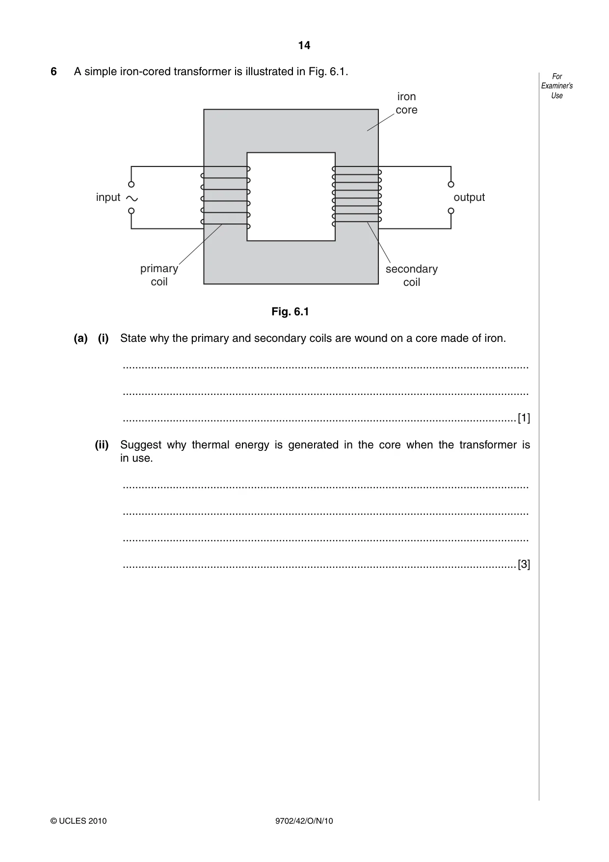
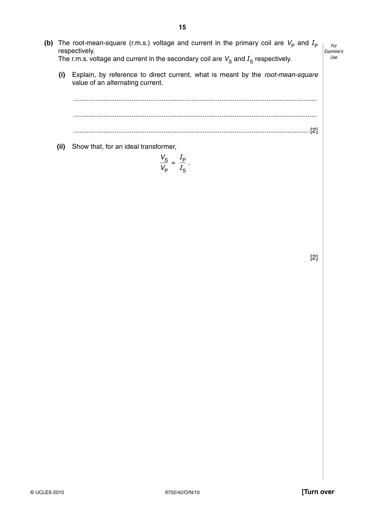
6 A simple iron-cored transformer is illustrated in Fig. 6.1. For Examiner’s iron Use core input output primary secondary coil coil Fig. 6.1 (a) (i) State why the primary and secondary coils are wound on a core made of iron. .................................................................................................................................. .................................................................................................................................. ..............................................................................................................................[1] (ii) Suggest why thermal energy is generated in the core when the transformer is in use. .................................................................................................................................. .................................................................................................................................. .................................................................................................................................. ..............................................................................................................................[3] (b) The root-mean-square (r.m.s.) voltage and current in the primary coil are VP and IP For respectively. Examiner’s The r.m.s. voltage and current in the secondary coil are VS and IS respectively. Use (i) Explain, by reference to direct current, what is meant by the root-mean-square value of an alternating current. .................................................................................................................................. .................................................................................................................................. ..............................................................................................................................[2] (ii) Show that, for an ideal transformer, VS IP = . VP IS [2]
Mark scheme: 6 (a) (i) e.g. prevent flux losses / improve flux linkage B1 [1] (ii) flux in core is changing B1 e.m.f. / current (induced) in core B1 induced current in core causes heating B1 [3] (b) (i) that value of the direct current producing same (mean) power / heating M1 in a resistor A1 [2] (ii) power in primary = power in secondary M1 VP IP = VS IS A1 [2]
Q7 · State an effect, one in each case, that provides evidence for For Examiner’s (i) the wave…
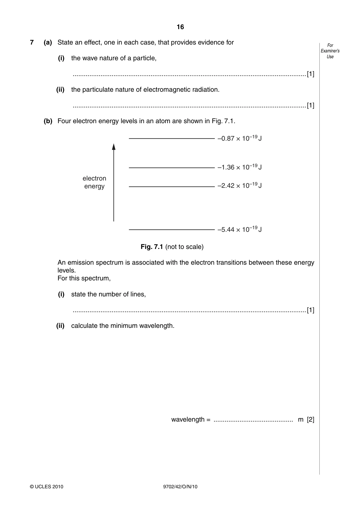
7 (a) State an effect, one in each case, that provides evidence for For Examiner’s (i) the wave nature of a particle, Use ..............................................................................................................................[1] (ii) the particulate nature of electromagnetic radiation. ..............................................................................................................................[1] (b) Four electron energy levels in an atom are shown in Fig. 7.1. –0.87 × 10⁻¹⁹ J –1.36 × 10⁻¹⁹ J electron energy –2.42 × 10⁻¹⁹ J –5.44 × 10⁻¹⁹ J Fig. 7.1 (not to scale) An emission spectrum is associated with the electron transitions between these energy levels. For this spectrum, (i) state the number of lines, ..............................................................................................................................[1] (ii) calculate the minimum wavelength. wavelength = ........................................... m [2]
Mark scheme: 7 (a) (i) e.g. electron / particle diffraction B1 [1] (ii) e.g. photoelectric effect B1 [1] (b) (i) 6 A1 [1] (ii) change in energy = 4.57 × 10⁻¹⁹ J λ = hc / E C1 = (6.63 × 10–34 × 3.0 × 108) / (4.57 × 10⁻¹⁹) = 4.4 × 10⁻⁷ m A1 [2]
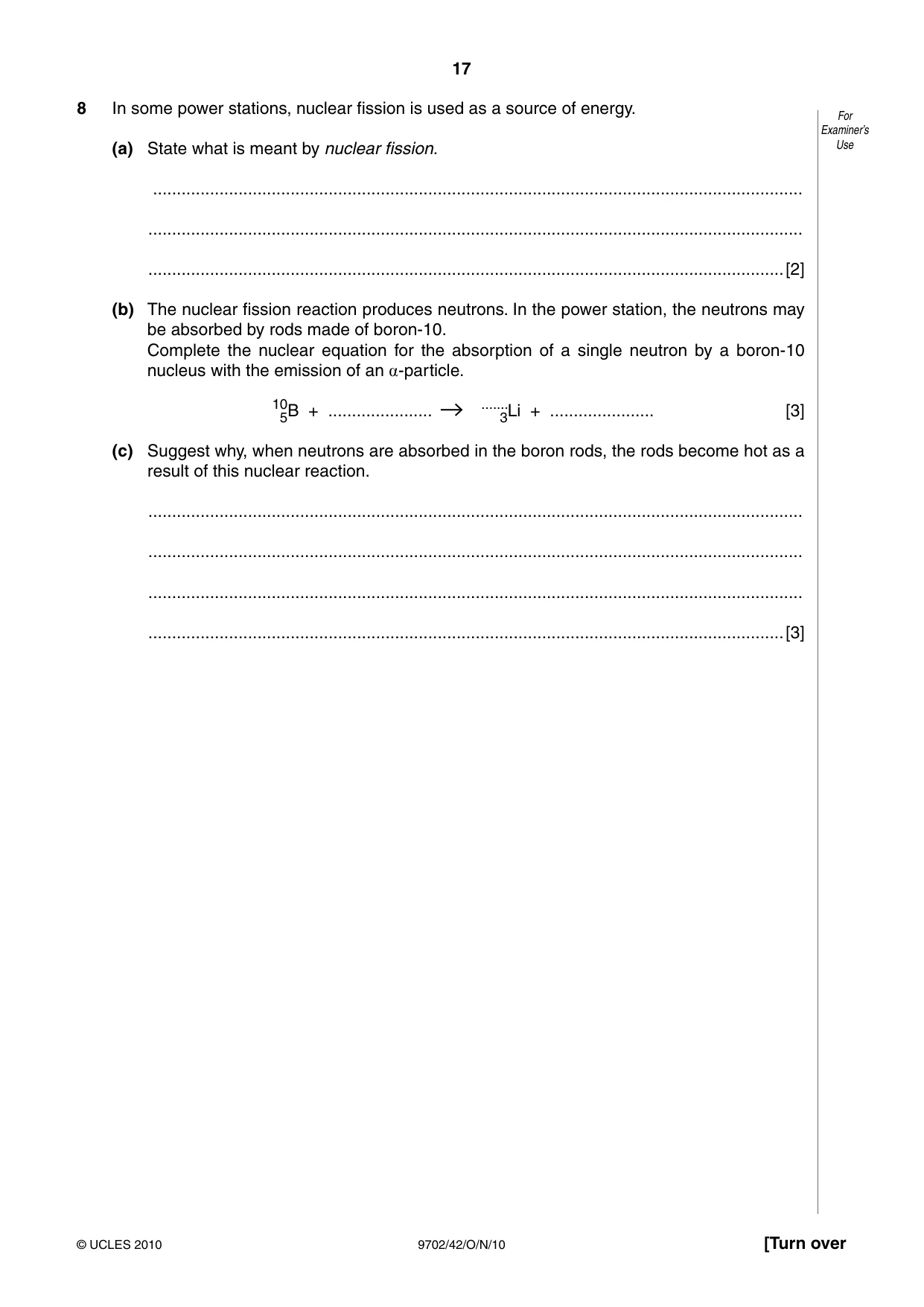
Q8 · In some power stations, nuclear fission is used as a source of energy
8 In some power stations, nuclear fission is used as a source of energy. For Examiner’s (a) State what is meant by nuclear fission. Use ......................................................................................................................................... .......................................................................................................................................... ......................................................................................................................................[2] (b) The nuclear fission reaction produces neutrons. In the power station, the neutrons may be absorbed by rods made of boron-10. Complete the nuclear equation for the absorption of a single neutron by a boron-10 nucleus with the emission of an a-particle. 10 ....... 5B + ...................... 3Li + ...................... [3] (c) Suggest why, when neutrons are absorbed in the boron rods, the rods become hot as a result of this nuclear reaction. .......................................................................................................................................... .......................................................................................................................................... .......................................................................................................................................... ......................................................................................................................................[3]
Mark scheme: 8 (a) splitting of a heavy nucleus (not atom/nuclide) M1 into two (lighter) nuclei of approximately same mass A1 [2] (b) 01 n 4 2 He (allow 42 α ) M2 7 3 Li A1 [3] (c) emitted particles have kinetic energy B1 range of particles in the control rods is short / particles stopped in rods / lose kinetic energy in rods B1 kinetic energy of particles converted to thermal energy B1 [3] GCE AS/A LEVEL – October/November 2010 9702 42 Section B
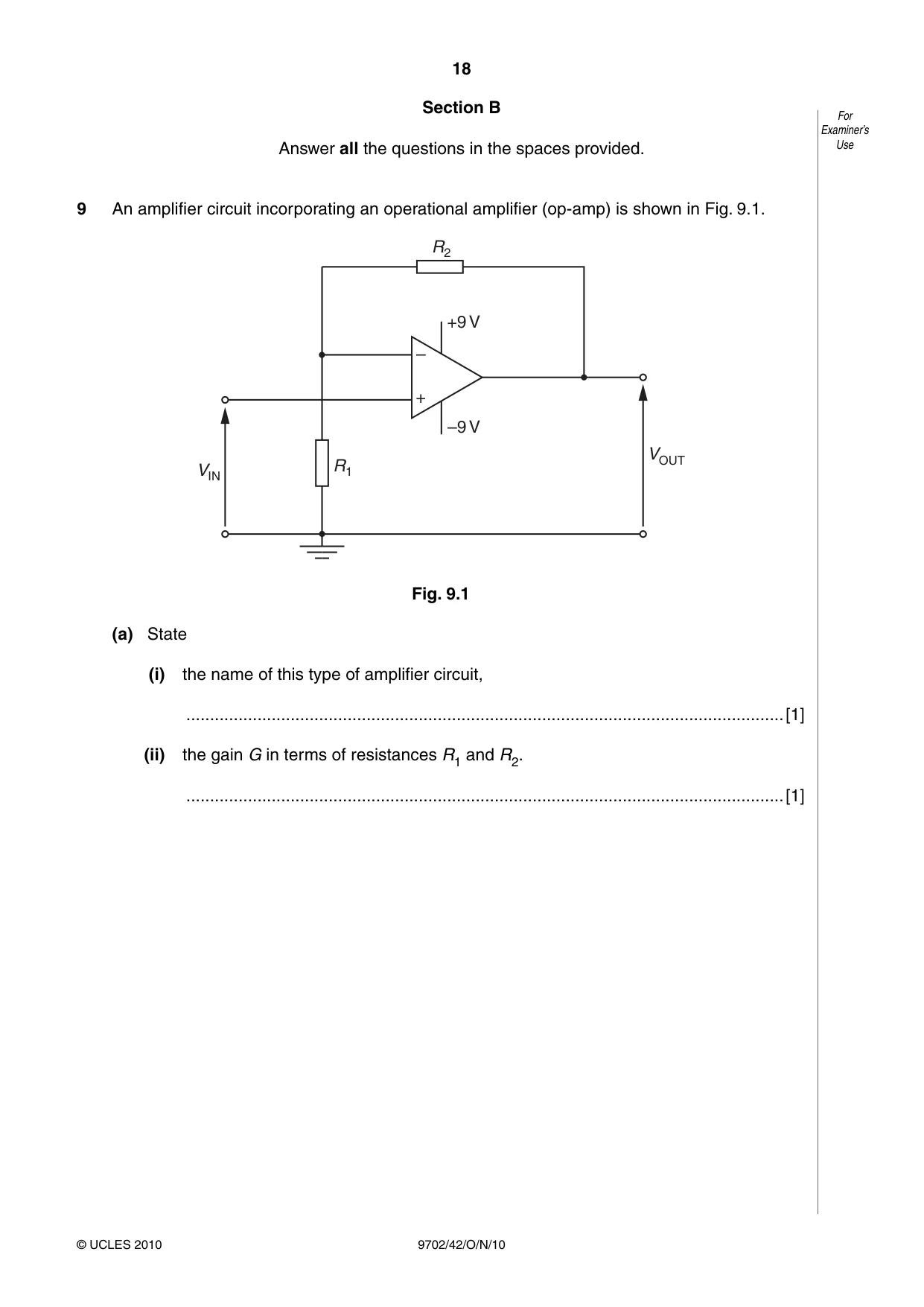
Q9 · An amplifier circuit incorporating an operational amplifier (op-amp) is shown in Fig
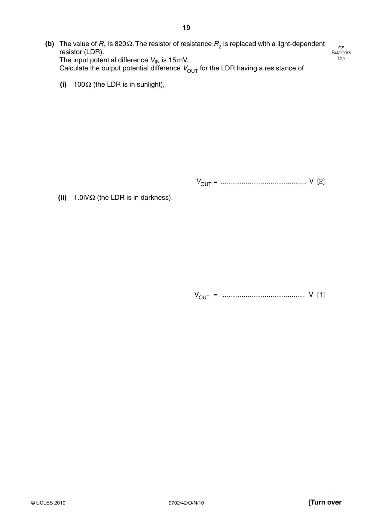
9 An amplifier circuit incorporating an operational amplifier (op-amp) is shown in Fig. 9.1. R2 +9 V – + –9 V VOUT VIN R1 Fig. 9.1 (a) State (i) the name of this type of amplifier circuit, ..............................................................................................................................[1] (ii) the gain G in terms of resistances R1 and R2. ..............................................................................................................................[1] (b) The value of R1 is 820 Ω. The resistor of resistance R2 is replaced with a light-dependent For resistor (LDR). Examiner’s The input potential difference VIN is 15 mV. Use Calculate the output potential difference VOUT for the LDR having a resistance of (i) 100 Ω (the LDR is in sunlight), VOUT = ............................................. V [2] (ii) 1.0 MΩ (the LDR is in darkness). VOUT = ........................................... V [1]
Mark scheme: 9 (a) (i) non-inverting (amplifier) B1 [1] (ii) (G =) 1 + R2 / R1 B1 [1] (b) (i) gain = 1 + 100 / 820 C1 output = 17 mV A1 [2] (ii) 9 V A1 [1] (R2 / R1 scores 0 in (a)(ii) but possible 1 mark in each of (b)(i) and (b)(ii) (1 + R1 / R2) scores 0 in (a)(ii), no mark in (b)(i), possible 1 mark in (b)(ii) (1 – R2 / R1) or R1 / R2 scores 0 in (a)(ii), (b)(i) and (b)(ii))
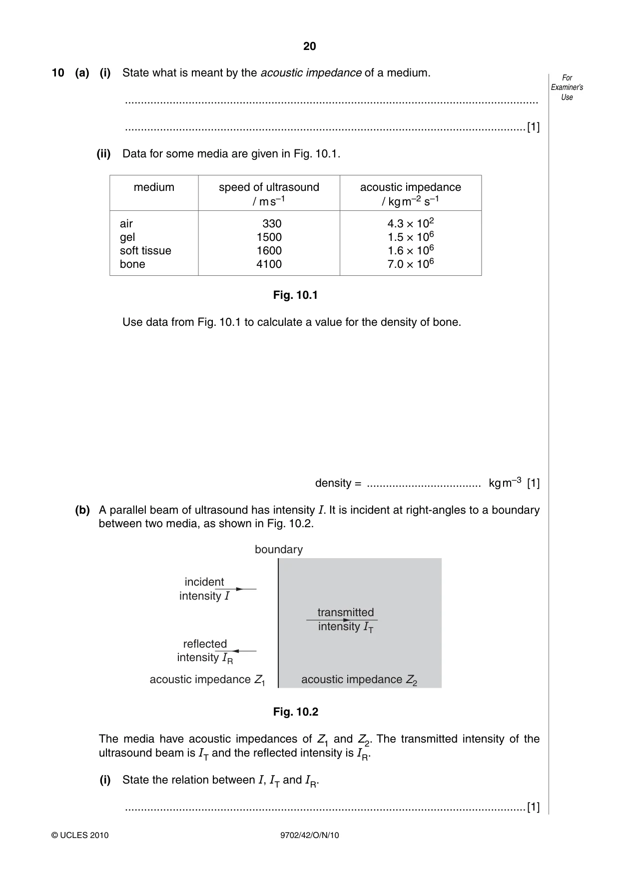
Q10 · State what is meant by the acoustic impedance of a medium
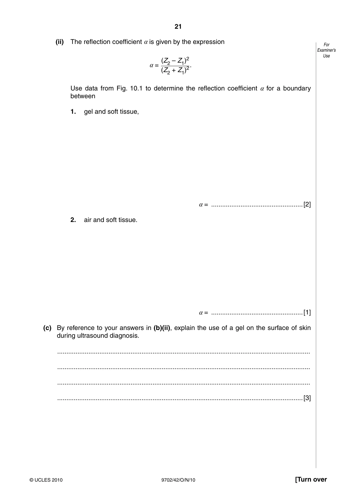
10 (a) (i) State what is meant by the acoustic impedance of a medium. For Examiner’s .................................................................................................................................. Use ..............................................................................................................................[1] (ii) Data for some media are given in Fig. 10.1. medium speed of ultrasound acoustic impedance / m s–1 / kg m–2 s–1 air 330 4.3 × 10² gel 1500 1.5 × 10⁶ soft tissue 1600 1.6 × 10⁶ bone 4100 7.0 × 10⁶ Fig. 10.1 Use data from Fig. 10.1 to calculate a value for the density of bone. density = .................................... kg m–3 [1] (b) A parallel beam of ultrasound has intensity I. It is incident at right-angles to a boundary between two media, as shown in Fig. 10.2. boundary incident intensity I transmitted intensity IT reflected intensity IR acoustic impedance Z1 acoustic impedance Z2 Fig. 10.2 The media have acoustic impedances of Z1 and Z2. The transmitted intensity of the ultrasound beam is IT and the reflected intensity is IR. (i) State the relation between I, IT and IR. ..............................................................................................................................[1] (ii) The reflection coefficient a is given by the expression For Examiner’s Use (Z2 – Z1)2 a = (Z2 + Z1)2. Use data from Fig. 10.1 to determine the reflection coefficient a for a boundary between 1. gel and soft tissue, a = ..................................................[2] 2. air and soft tissue. a = ..................................................[1] (c) By reference to your answers in (b)(ii), explain the use of a gel on the surface of skin during ultrasound diagnosis. .......................................................................................................................................... .......................................................................................................................................... .......................................................................................................................................... ......................................................................................................................................[3]
Mark scheme: 10 (a) (i) density × speed of wave (in the medium) B1 [1] (ii) ρ = (7.0 × 10⁶) / 4100 = 1700 kg m–3 A1 [1] (b) (i) I = IT + IR B1 [1] (ii) 1. α = (0.1 × 10⁶)2 / (3.1 × 10⁶)2 C1 = 0.001 A1 [2] 2. α ≈ 1 A1 [1] (c) either very little transmission at an air-skin boundary M1 (almost) complete transmission at a gel-skin boundary M1 when wave travels in or out of the body A1 [3] or no gel, majority reflection (M1) with gel, little reflection (M1) when wave travels in or out of the body (A1)
Q11 · Wire pairs provide one means of communication but they are subject to high levels of For…
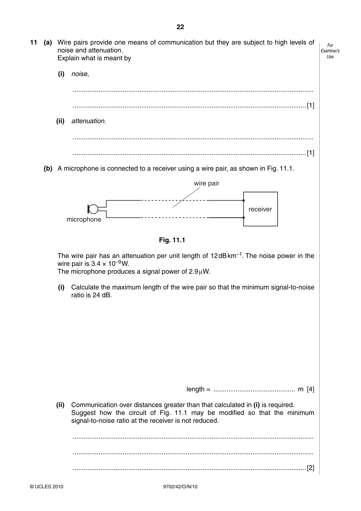
11 (a) Wire pairs provide one means of communication but they are subject to high levels of For noise and attenuation. Examiner’s Explain what is meant by Use (i) noise, .................................................................................................................................. ..............................................................................................................................[1] (ii) attenuation. .................................................................................................................................. ..............................................................................................................................[1] (b) A microphone is connected to a receiver using a wire pair, as shown in Fig. 11.1. wire pair receiver microphone Fig. 11.1 The wire pair has an attenuation per unit length of 12 dB km–1. The noise power in the wire pair is 3.4 × 10⁻⁹ W. The microphone produces a signal power of 2.9 lW. (i) Calculate the maximum length of the wire pair so that the minimum signal-to-noise ratio is 24 dB. length = ............................................ m [4] (ii) Communication over distances greater than that calculated in (i) is required. Suggest how the circuit of Fig. 11.1 may be modified so that the minimum signal-to-noise ratio at the receiver is not reduced. .................................................................................................................................. .................................................................................................................................. ..............................................................................................................................[2]
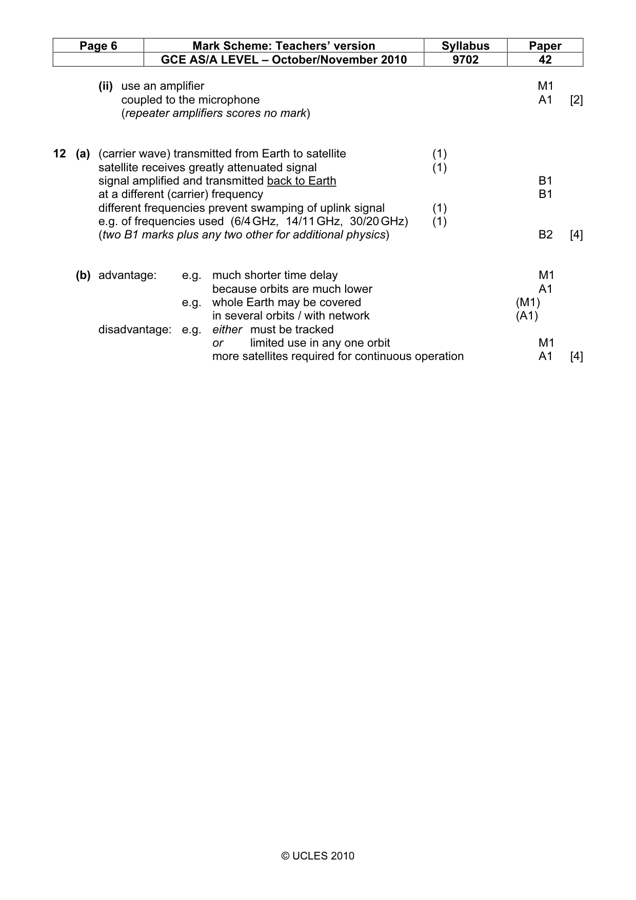
Mark scheme: 11 (a) (i) unwanted random power / signal / energy B1 [1] (ii) loss of (signal) power / energy B1 [1] (b) (i) either signal-to-noise ratio at mic. = 10 lg (P2 / P1) C1 = 10 lg ({2.9 × 10⁻⁶} / {3.4 × 10⁻⁹}) = 29 dB A1 maximum length = (29 – 24) / 12 C1 = 0.42 km = 420 m A1 [4] or signal-to-noise ratio at receiver = 10 lg (P2 / P1) (C1) at receiver, 24 = 10 lg(P / {3.4 × 10⁻⁹}) P = 8.54 × 10⁻⁷ W (A1) power loss in cables = 10 lg({2.9 × 10⁻⁶} / {8.54 × 10⁻⁷}) (C1) = 5.3 dB length = 5.3 / 12 km = 440 m (A1) GCE AS/A LEVEL – October/November 2010 9702 42 (ii) use an amplifier M1 coupled to the microphone A1 [2] (repeater amplifiers scores no mark)
Q12 · Outline the principles of the use of a geostationary satellite for communication on For…
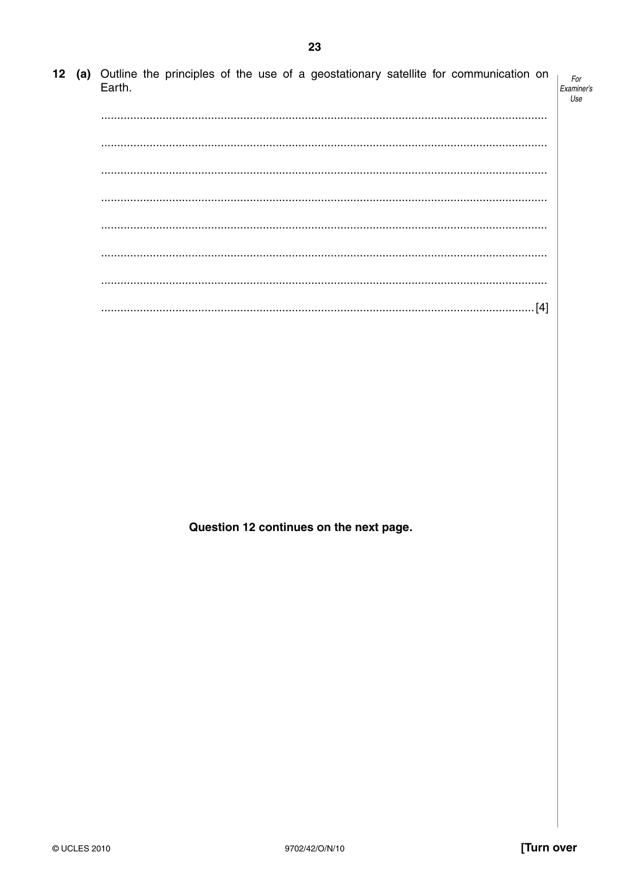
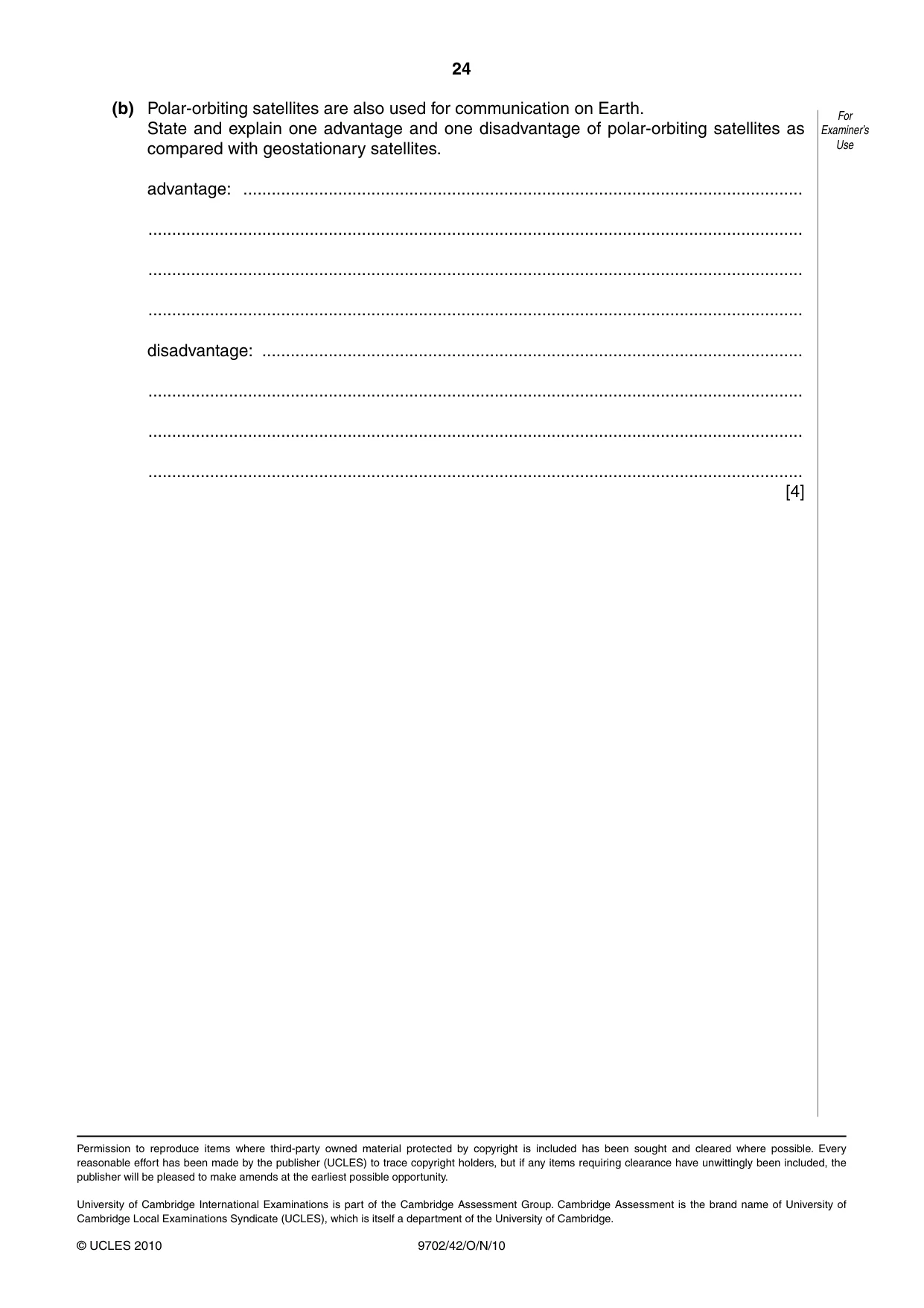
12 (a) Outline the principles of the use of a geostationary satellite for communication on For Earth. Examiner’s Use .......................................................................................................................................... .......................................................................................................................................... .......................................................................................................................................... .......................................................................................................................................... .......................................................................................................................................... .......................................................................................................................................... .......................................................................................................................................... ......................................................................................................................................[4] Question 12 continues on the next page. (b) Polar-orbiting satellites are also used for communication on Earth. For State and explain one advantage and one disadvantage of polar-orbiting satellites as Examiner’s compared with geostationary satellites. Use advantage: ...................................................................................................................... .......................................................................................................................................... .......................................................................................................................................... .......................................................................................................................................... disadvantage: .................................................................................................................. .......................................................................................................................................... .......................................................................................................................................... .......................................................................................................................................... [4]
Mark scheme: 12 (a) (carrier wave) transmitted from Earth to satellite (1) satellite receives greatly attenuated signal (1) signal amplified and transmitted back to Earth B1 at a different (carrier) frequency B1 different frequencies prevent swamping of uplink signal (1) e.g. of frequencies used (6/4 GHz, 14/11 GHz, 30/20 GHz) (1) (two B1 marks plus any two other for additional physics) B2 [4] (b) advantage: e.g. much shorter time delay M1 because orbits are much lower A1 e.g. whole Earth may be covered (M1) in several orbits / with network (A1) disadvantage: e.g. either must be tracked or limited use in any one orbit M1 more satellites required for continuous operation A1 [4]
What was in this paper
The subtopics covered by these 12 questions, and how many questions each got. Open one in a new tab to see every Cambridge question on it.
What you needed in this session
Cambridge’s own grade thresholds for 2010 Oct/Nov, Paper 4 · Variant 2. A higher threshold means an easier paper — the bar moves with how the cohort did.