Questions as text
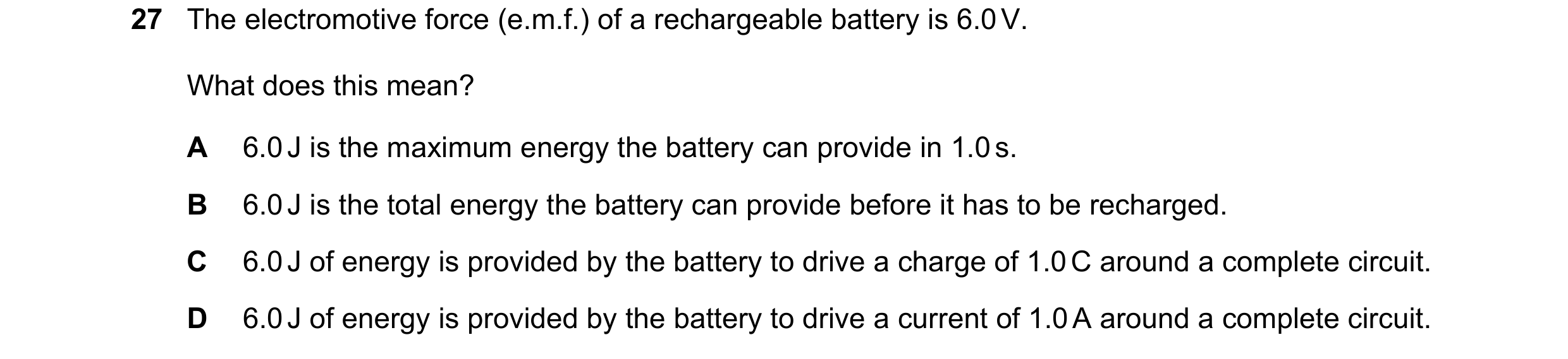
Q1 · The electromotive force (e.m.f.) of a rechargeable battery is 6.0 V 0972/21 May/June 2018
27 The electromotive force (e.m.f.) of a rechargeable battery is 6.0 V. What does this mean? A 6.0 J is the maximum energy the battery can provide in 1.0 s. B 6.0 J is the total energy the battery can provide before it has to be recharged. C 6.0 J of energy is provided by the battery to drive a charge of 1.0 C around a complete circuit. D 6.0 J of energy is provided by the battery to drive a current of 1.0 A around a complete circuit.
1 marks
Answer: C
This question in 0972/21 May/June 2018
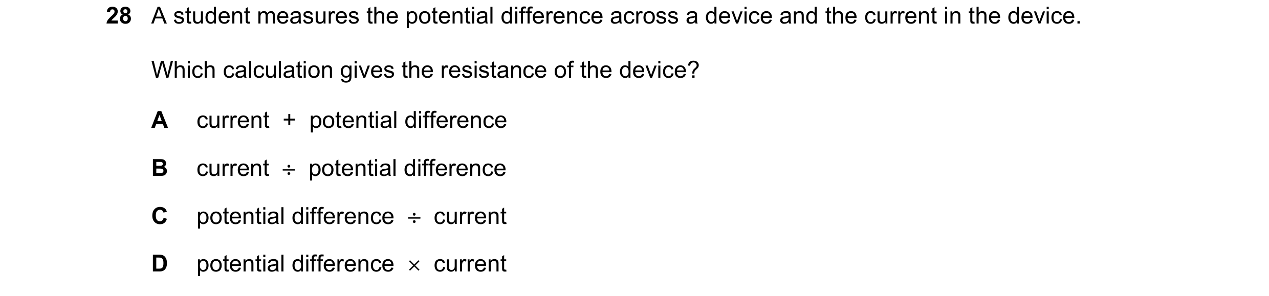
Q2 · A student measures the potential difference across a device and the current in the device 0972/21 May/June 2018
28 A student measures the potential difference across a device and the current in the device. Which calculation gives the resistance of the device? A current + potential difference B current ÷ potential difference C potential difference ÷ current D potential difference × current
1 marks
Answer: C
This question in 0972/21 May/June 2018
Q3 · A water heater is connected to a 230 V supply and there is a current of 26 A in the heater 0972/21 May/June 2018
29 A water heater is connected to a 230 V supply and there is a current of 26 A in the heater. It takes 20 minutes to heat the water to the required temperature. How much energy is supplied by the heater? A 6.0 × 10³ J B 1.0 × 10⁴ J C 1.2 × 10⁵ J D 7.2 × 10⁶ J
1 marks
Answer: D
This question in 0972/21 May/June 2018
Q4 · Which electrical symbol represents a diode? 0972/21 May/June 2018
30 Which electrical symbol represents a diode? A B C D
1 marks
Answer: B
This question in 0972/21 May/June 2018
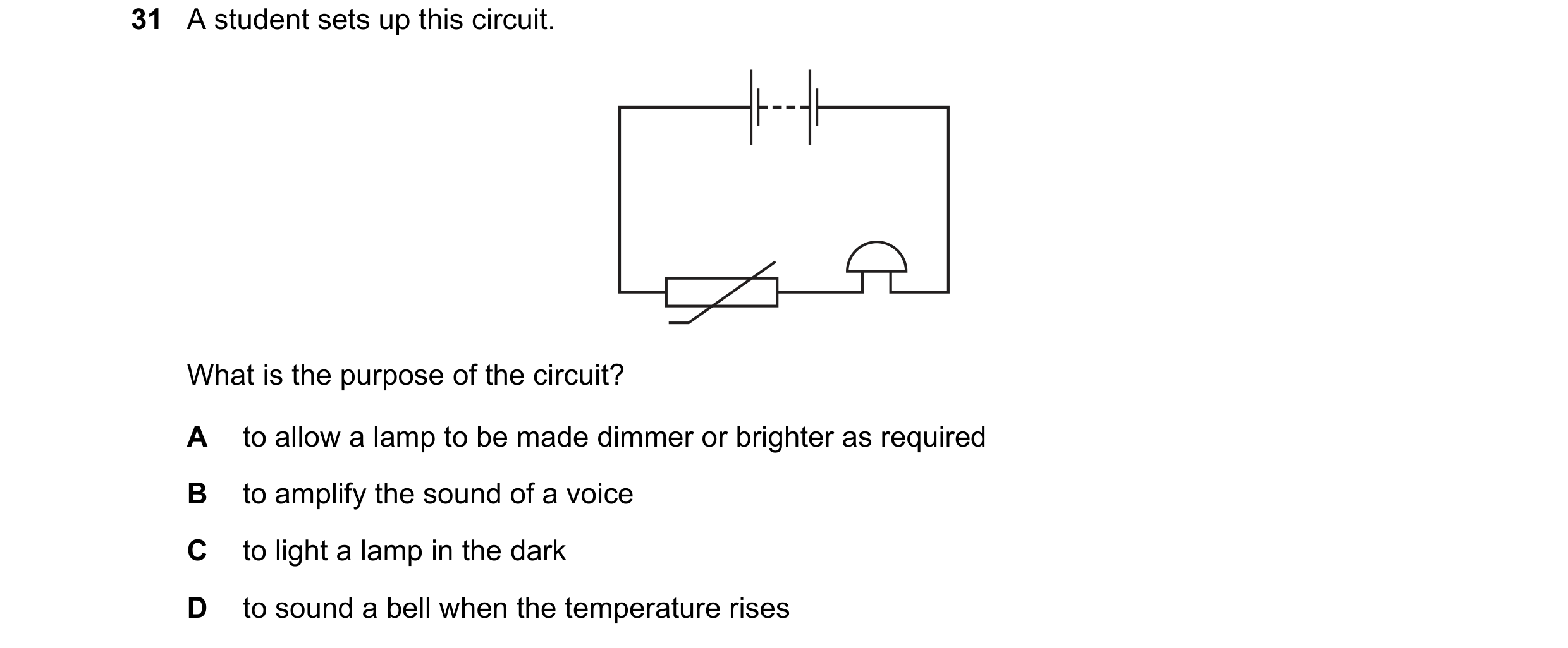
Q5 · A student sets up this circuit 0972/21 May/June 2018
31 A student sets up this circuit. What is the purpose of the circuit? A to allow a lamp to be made dimmer or brighter as required B to amplify the sound of a voice C to light a lamp in the dark D to sound a bell when the temperature rises
1 marks
Answer: D
This question in 0972/21 May/June 2018
Q6 · The diagram shows two voltmeters P and Q connected to a potential divider 0972/21 May/June 2018
32 The diagram shows two voltmeters P and Q connected to a potential divider. V voltmeter P X V voltmeter Q The sliding connection at point X is moved towards the top of the diagram. What happens to the reading on P and to the reading on Q? reading on P reading on Q A decreases decreases B decreases increases C increases decreases D increases increases
1 marks
Answer: B
This question in 0972/21 May/June 2018
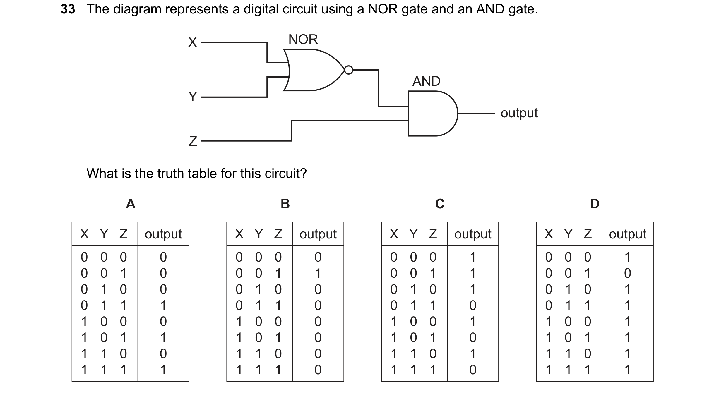
Q7 · The diagram represents a digital circuit using a NOR gate and an AND gate 0972/21 May/June 2018
33 The diagram represents a digital circuit using a NOR gate and an AND gate. X NOR AND Y output Z What is the truth table for this circuit? A B C D X Y Z output X Y Z output X Y Z output X Y Z output 0 0 0 0 0 0 0 0 0 0 0 1 0 0 0 1 0 0 1 0 0 0 1 1 0 0 1 1 0 0 1 0 0 1 0 0 0 1 0 0 0 1 0 1 0 1 0 1 0 1 1 1 0 1 1 0 0 1 1 0 0 1 1 1 1 0 0 0 1 0 0 0 1 0 0 1 1 0 0 1 1 0 1 1 1 0 1 0 1 0 1 0 1 0 1 1 1 1 0 0 1 1 0 0 1 1 0 1 1 1 0 1 1 1 1 1 1 1 1 0 1 1 1 0 1 1 1 1
1 marks
Answer: B
This question in 0972/21 May/June 2018
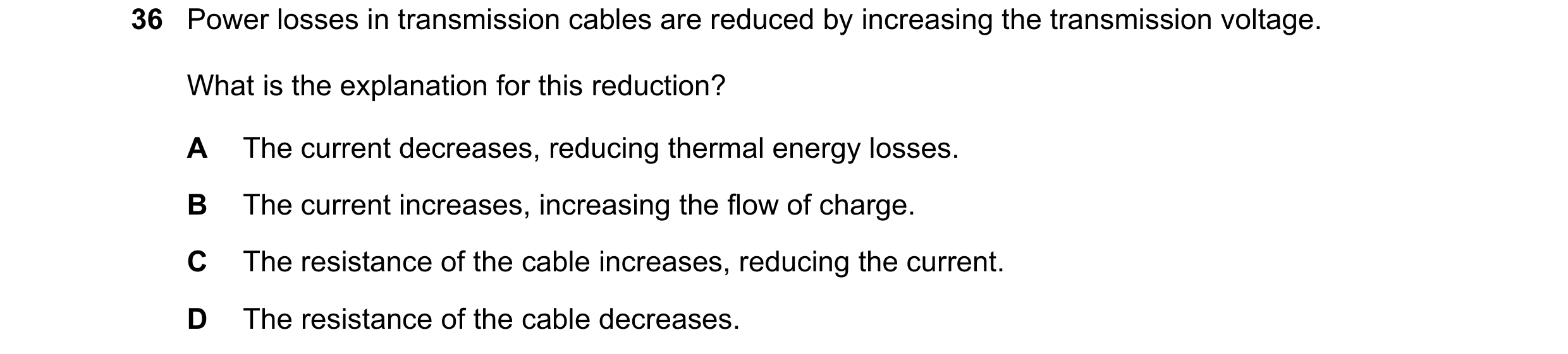
Q8 · Power losses in transmission cables are reduced by increasing the transmission voltage 0972/21 May/June 2018
36 Power losses in transmission cables are reduced by increasing the transmission voltage. What is the explanation for this reduction? A The current decreases, reducing thermal energy losses. B The current increases, increasing the flow of charge. C The resistance of the cable increases, reducing the current. D The resistance of the cable decreases.
1 marks
Answer: A
This question in 0972/21 May/June 2018
Q9 · A bar magnet is placed inside a current-carrying coil 0972/21 Oct/Nov 2018
27 A bar magnet is placed inside a current-carrying coil. The diagram shows four different experiments. 1 2 magnet slowly magnet slowly removed removed + – 3 4 current in coil current in coil slowly reduced slowly reduced + – In which experiments is the magnet demagnetised? A 1 and 2 B 1 and 3 C 2 and 4 D 3 and 4
1 marks
Answer: B
This question in 0972/21 Oct/Nov 2018
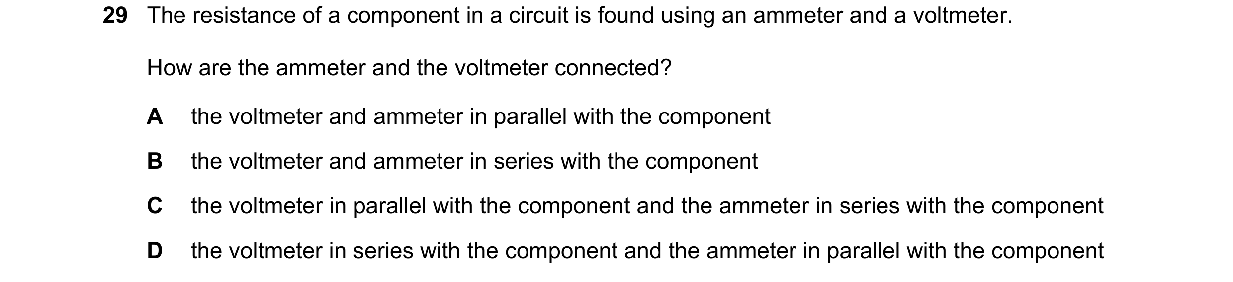
Q10 · The resistance of a component in a circuit is found using an ammeter and a voltmeter 0972/21 Oct/Nov 2018
29 The resistance of a component in a circuit is found using an ammeter and a voltmeter. How are the ammeter and the voltmeter connected? A the voltmeter and ammeter in parallel with the component B the voltmeter and ammeter in series with the component C the voltmeter in parallel with the component and the ammeter in series with the component D the voltmeter in series with the component and the ammeter in parallel with the component
1 marks
Answer: C
This question in 0972/21 Oct/Nov 2018
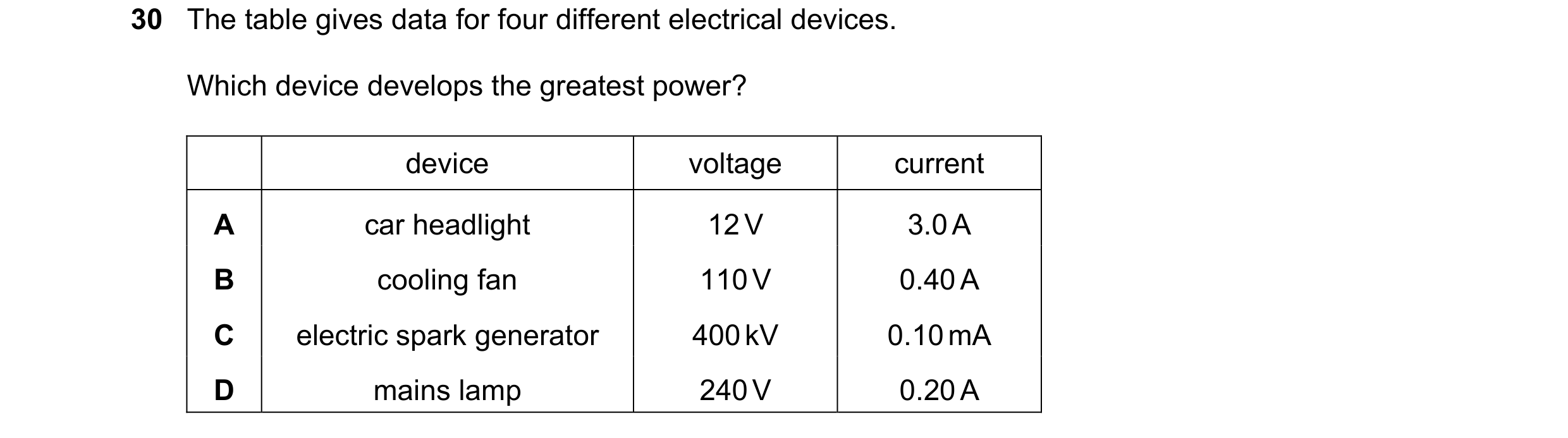
Q11 · The table gives data for four different electrical devices 0972/21 Oct/Nov 2018
30 The table gives data for four different electrical devices. Which device develops the greatest power? device voltage current A car headlight 12 V 3.0 A B cooling fan 110 V 0.40 A C electric spark generator 400 kV 0.10 mA D mains lamp 240 V 0.20 A
1 marks
Answer: D
This question in 0972/21 Oct/Nov 2018
Q12 · The circuit diagram shows a fixed resistor R and a thermistor T used in a potential… 0972/21 Oct/Nov 2018
31 The circuit diagram shows a fixed resistor R and a thermistor T used in a potential divider circuit. T R VR and VT are the potential differences across R and T respectively. What happens to VR and to VT as the temperature of the thermistor decreases? VR VT A decreases increases B increases decreases C stays the same decreases D stays the same increases
1 marks
Answer: A
This question in 0972/21 Oct/Nov 2018
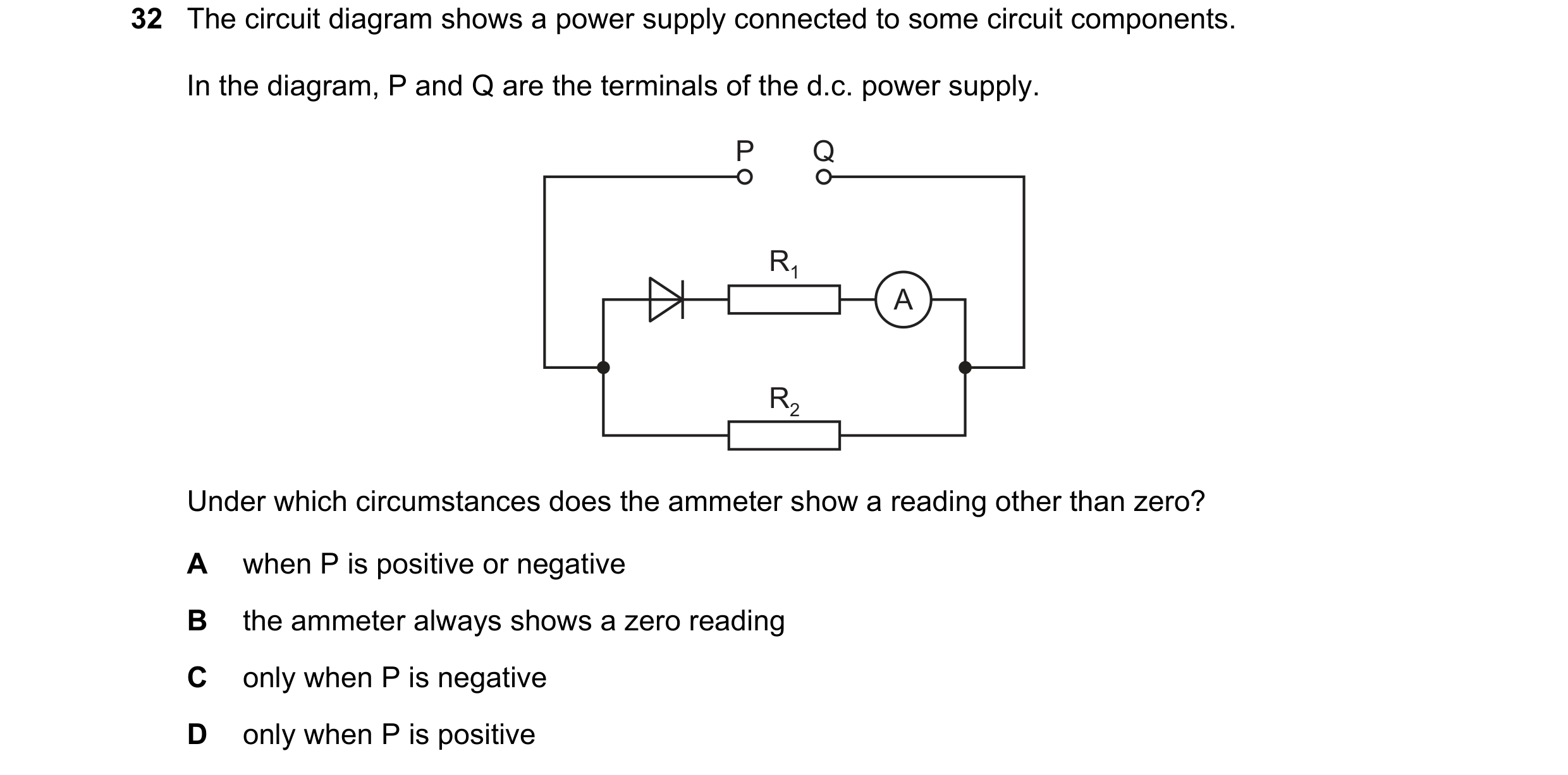
Q13 · The circuit diagram shows a power supply connected to some circuit components 0972/21 Oct/Nov 2018
32 The circuit diagram shows a power supply connected to some circuit components. In the diagram, P and Q are the terminals of the d.c. power supply. P Q R1 A R2 Under which circumstances does the ammeter show a reading other than zero? A when P is positive or negative B the ammeter always shows a zero reading C only when P is negative D only when P is positive
1 marks
Answer: D
This question in 0972/21 Oct/Nov 2018
Q14 · The diagram shows a digital circuit with two inputs and one output 0972/21 Oct/Nov 2018
33 The diagram shows a digital circuit with two inputs and one output. input 1 output input 2 What describes the action of the circuit? A AND B NAND C NOR D OR
1 marks
Answer: C
This question in 0972/21 Oct/Nov 2018
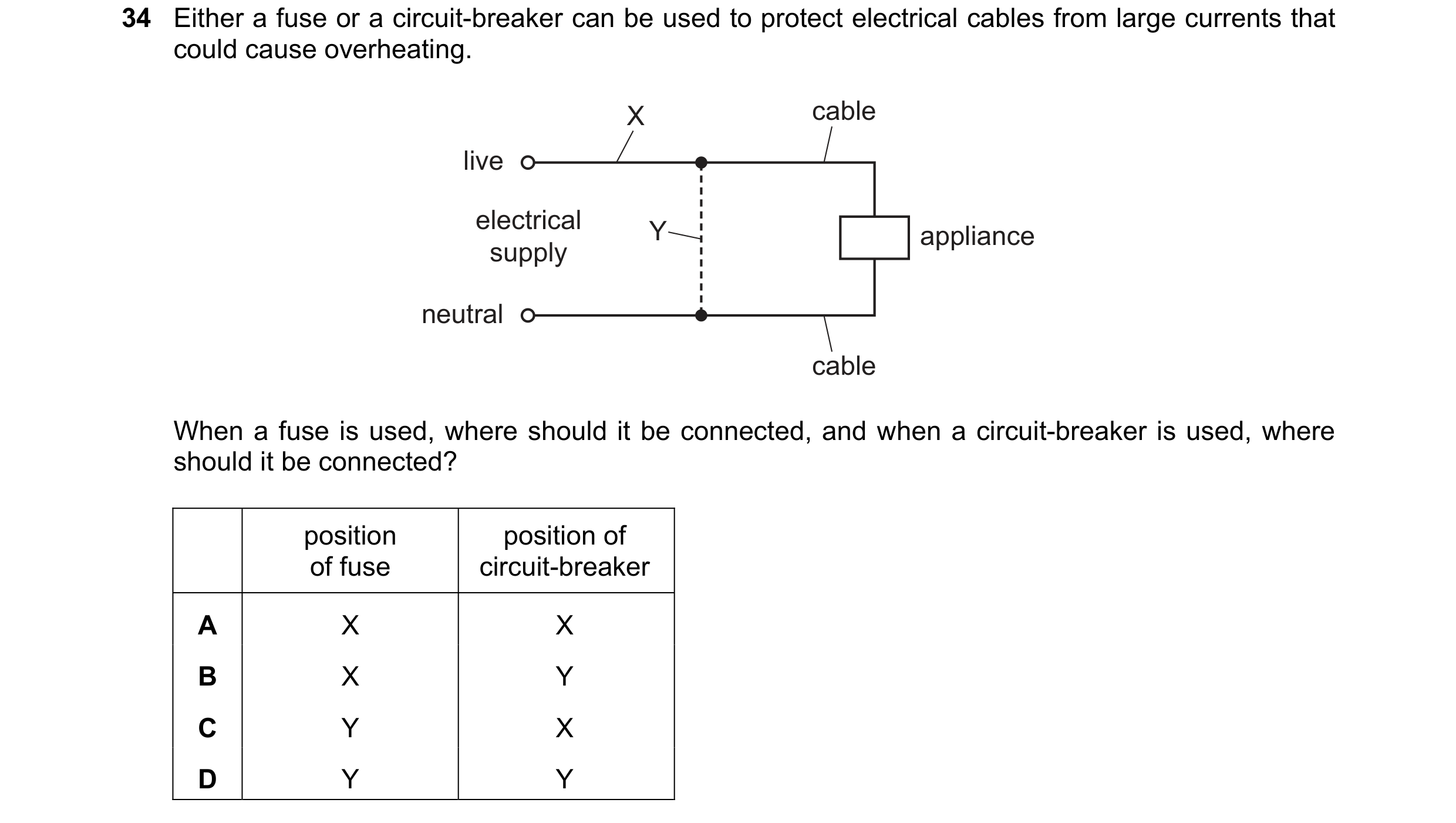
Q15 · Either a fuse or a circuit-breaker can be used to protect electrical cables from large… 0972/21 Oct/Nov 2018
34 Either a fuse or a circuit-breaker can be used to protect electrical cables from large currents that could cause overheating. X cable live electrical Y appliance supply neutral cable When a fuse is used, where should it be connected, and when a circuit-breaker is used, where should it be connected? position position of of fuse circuit-breaker A X X B X Y C Y X D Y Y
1 marks
Answer: A
This question in 0972/21 Oct/Nov 2018
Q16 · The diagram shows a circuit containing a d.c 0972/21 May/June 2019
30 The diagram shows a circuit containing a d.c. power supply, a motor and a variable resistor. Three ammeters X, Y and Z show the current in different parts of the circuit. + – X A A Z A M Y The reading on X is 4.0 A. Which statement is correct? A The readings on Y and Z are both less than 4.0 A. B The readings on Y and Z are both equal to 4.0 A. C The readings on Y and Z are both greater than 4.0 A. D The reading on Z is zero.
1 marks
Answer: B
This question in 0972/21 May/June 2019
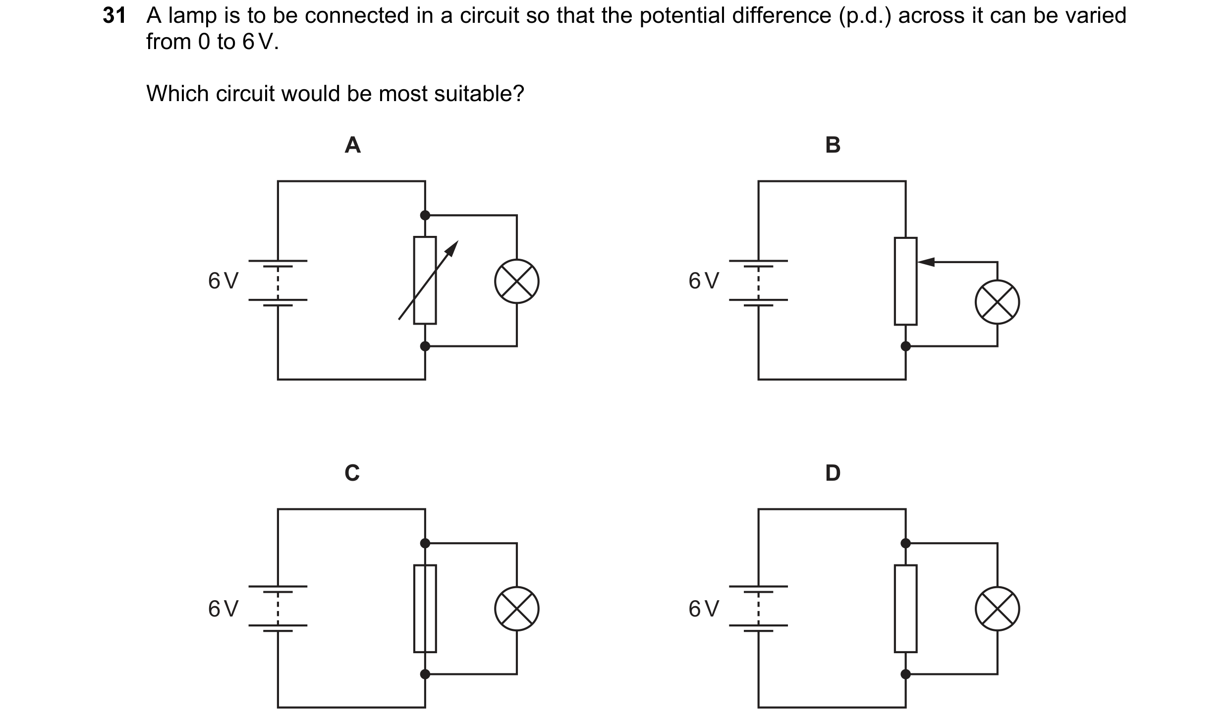
Q17 · A lamp is to be connected in a circuit so that the potential difference (p.d.) across it… 0972/21 May/June 2019
31 A lamp is to be connected in a circuit so that the potential difference (p.d.) across it can be varied from 0 to 6 V. Which circuit would be most suitable? A B 6 V 6 V C D 6 V 6 V
1 marks
Answer: B
This question in 0972/21 May/June 2019
Q18 · Which logic gate is represented by the symbol shown? 0972/21 May/June 2019
32 Which logic gate is represented by the symbol shown? A AND B NAND C NOR D OR
1 marks
Answer: A
This question in 0972/21 May/June 2019
Q19 · The diagram shows a combination of logic gates 0972/21 May/June 2019
33 The diagram shows a combination of logic gates. Which single logic gate is equivalent to this combination? A AND B NOR C NOT D OR
1 marks
Answer: B
This question in 0972/21 May/June 2019
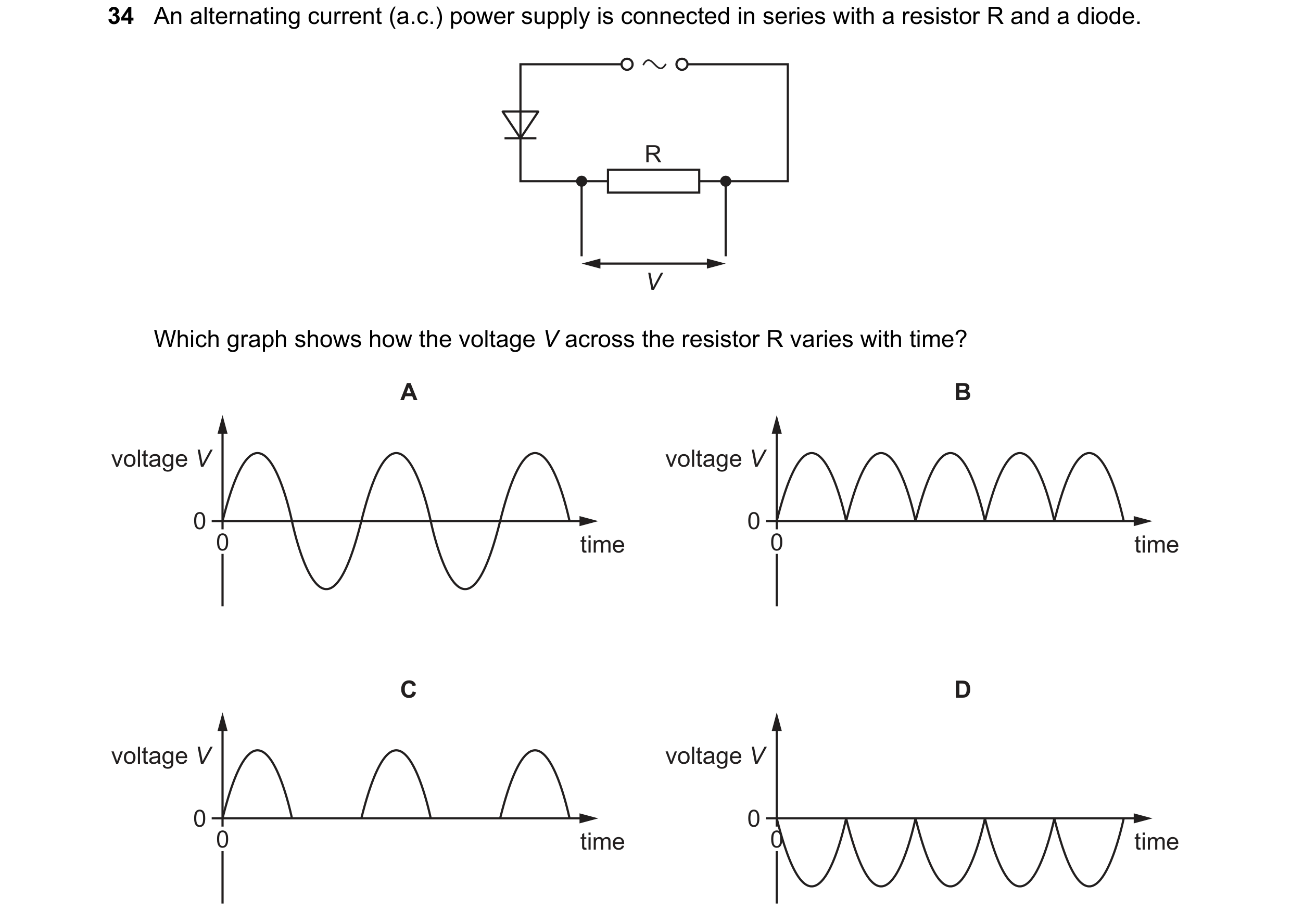
Q20 · An alternating current (a.c.) power supply is connected in series with a resistor R and a… 0972/21 May/June 2019
34 An alternating current (a.c.) power supply is connected in series with a resistor R and a diode. R V Which graph shows how the voltage V across the resistor R varies with time? A B voltage V voltage V 0 0 0 time 0 time C D voltage V voltage V 0 0 0 time 0 time
1 marks
Answer: C
This question in 0972/21 May/June 2019
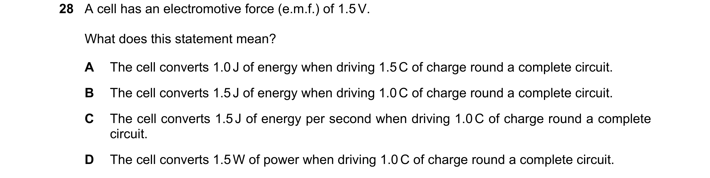
Q21 · A cell has an electromotive force (e.m.f.) of 1.5 V 0972/22 May/June 2019
28 A cell has an electromotive force (e.m.f.) of 1.5 V. What does this statement mean? A The cell converts 1.0 J of energy when driving 1.5 C of charge round a complete circuit. B The cell converts 1.5 J of energy when driving 1.0 C of charge round a complete circuit. C The cell converts 1.5 J of energy per second when driving 1.0 C of charge round a complete circuit. D The cell converts 1.5 W of power when driving 1.0 C of charge round a complete circuit.
1 marks
Answer: B
This question in 0972/22 May/June 2019
Q22 · The diagram shows a circuit 0972/22 May/June 2019
30 The diagram shows a circuit. What is connected in parallel with the thermistor? A heater B lamp C light-dependent resistor D variable resistor
1 marks
Answer: A
This question in 0972/22 May/June 2019
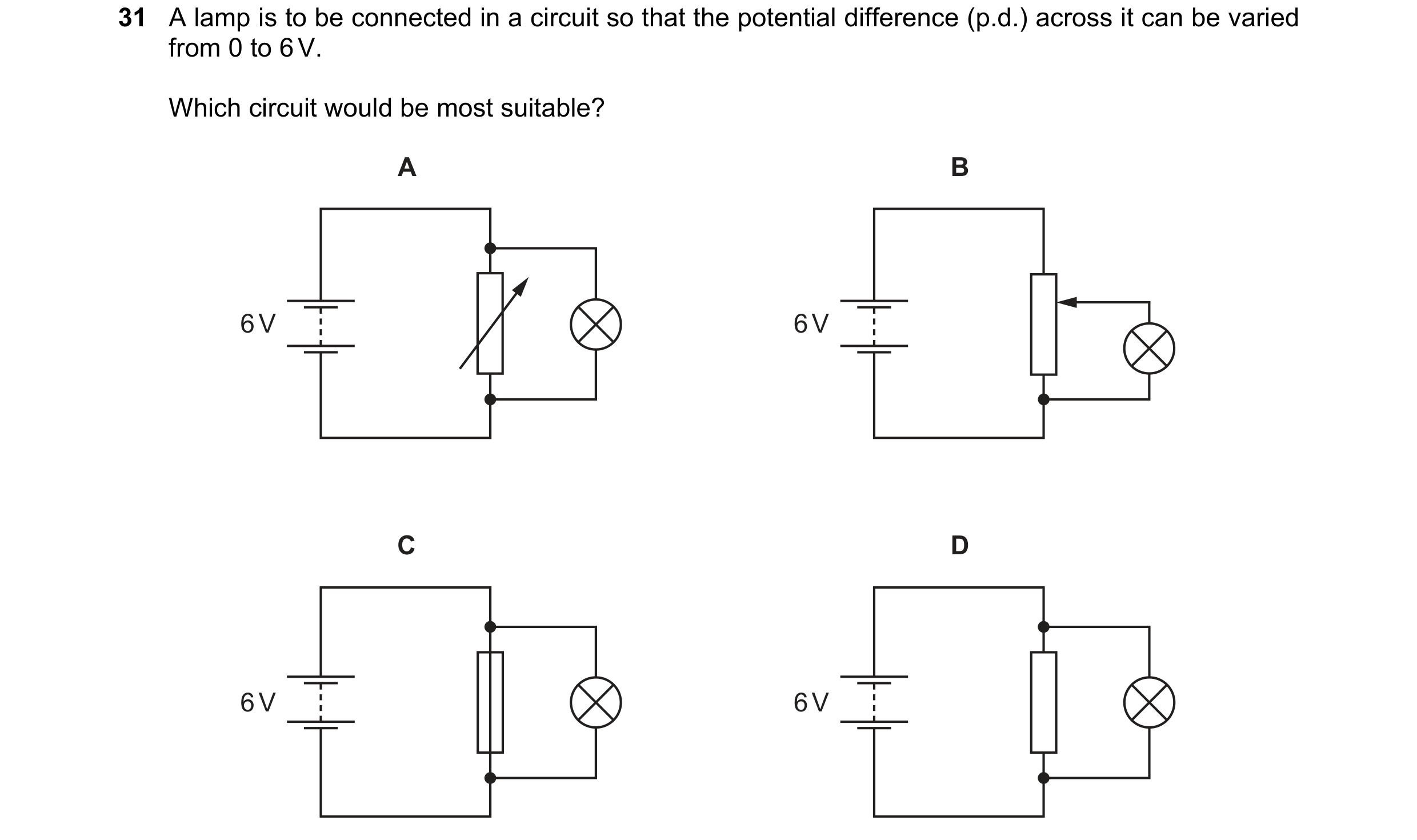
Q23 · A lamp is to be connected in a circuit so that the potential difference (p.d.) across it… 0972/22 May/June 2019
31 A lamp is to be connected in a circuit so that the potential difference (p.d.) across it can be varied from 0 to 6 V. Which circuit would be most suitable? A B 6 V 6 V C D 6 V 6 V
1 marks
Answer: B
This question in 0972/22 May/June 2019
Q24 · The circuit below can be completed by inserting components at X and at Y 0972/22 May/June 2019
32 The circuit below can be completed by inserting components at X and at Y. The completed circuit is a potential divider in which the potential difference across component Y increases when the temperature increases. X Y V Which row shows the components X and Y? X Y A light-dependent resistor resistor B resistor light-dependent resistor C resistor thermistor D thermistor resistor
1 marks
Answer: D
This question in 0972/22 May/June 2019
Q25 · Which two logic gates each have a high output (1) when both of their inputs are low (0)? 0972/22 May/June 2019
33 Which two logic gates each have a high output (1) when both of their inputs are low (0)? A AND and OR B AND and NOR C NAND and NOR D NAND and OR
1 marks
Answer: C
This question in 0972/22 May/June 2019
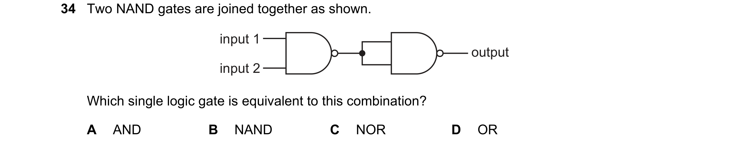
Q26 · Two NAND gates are joined together as shown 0972/22 May/June 2019
34 Two NAND gates are joined together as shown. input 1 output input 2 Which single logic gate is equivalent to this combination? A AND B NAND C NOR D OR
1 marks
Answer: A
This question in 0972/22 May/June 2019
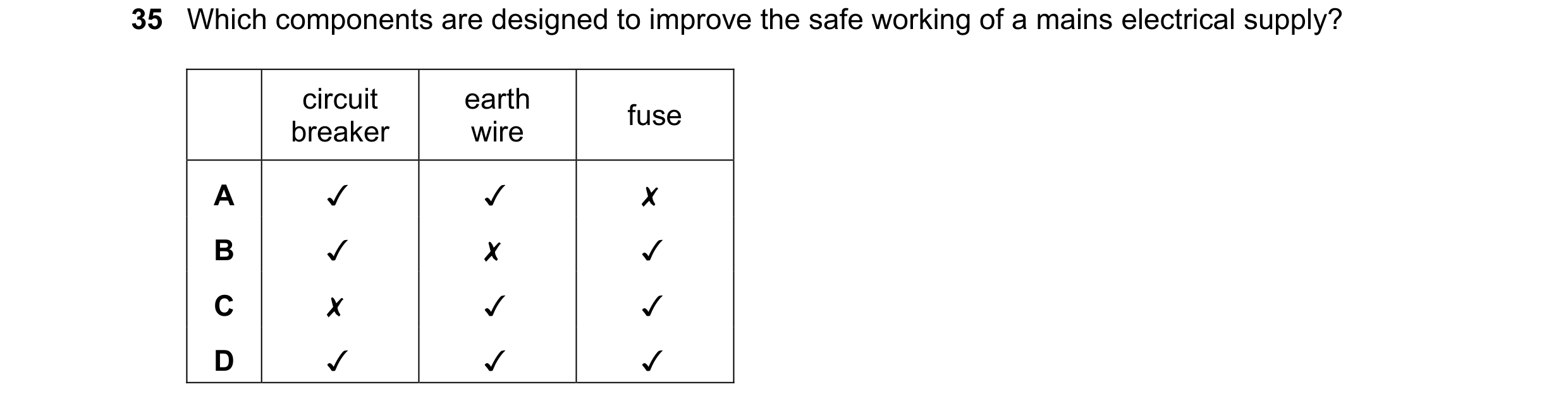
Q27 · Which components are designed to improve the safe working of a mains electrical supply? 0972/22 May/June 2019
35 Which components are designed to improve the safe working of a mains electrical supply?
circuit
breaker
1 marks
Answer: D
This question in 0972/22 May/June 2019
Q28 · A steel bar is placed in an East-West direction for it to be demagnetised 0972/21 Oct/Nov 2019
26 A steel bar is placed in an East-West direction for it to be demagnetised. No other magnet is nearby. Which method is not suitable? A Hammering the bar. B Heating the bar to a very high temperature. C Slowly taking the bar out of a coil that carries an alternating current. D Slowly taking the bar out of a coil that carries a direct current.
1 marks
Answer: D
This question in 0972/21 Oct/Nov 2019
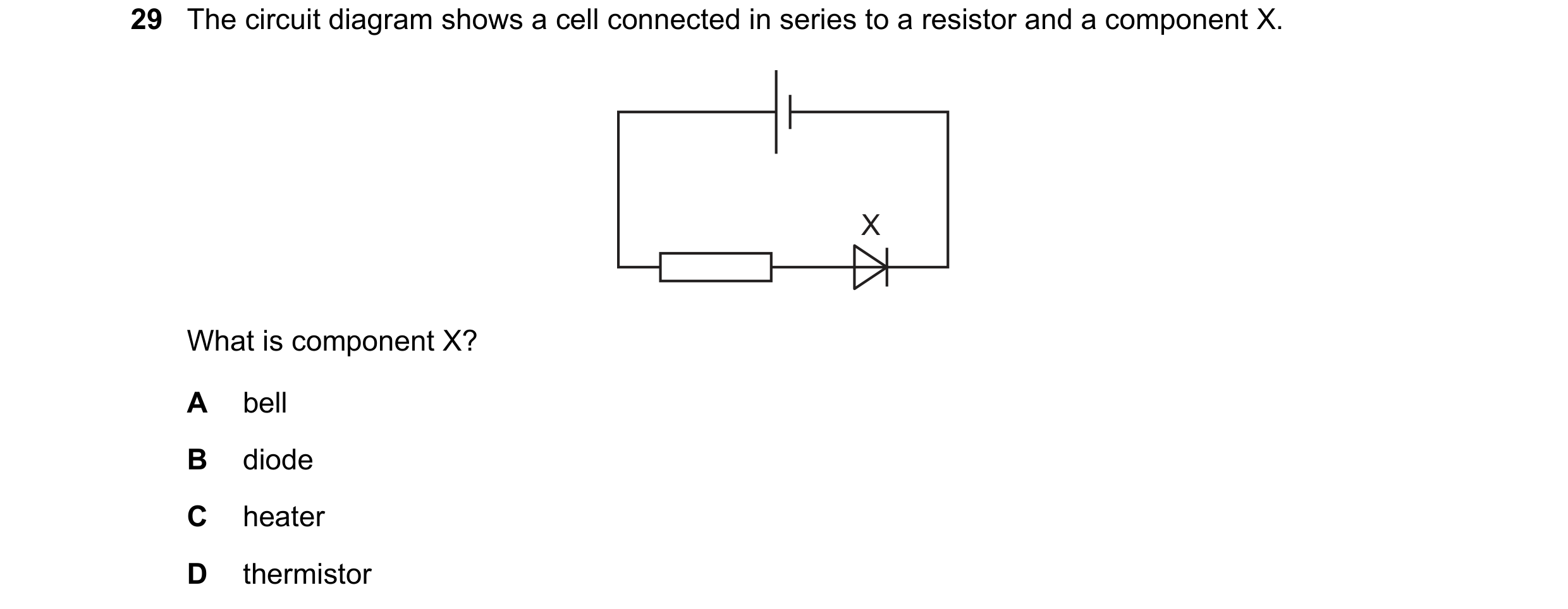
Q29 · The circuit diagram shows a cell connected in series to a resistor and a component X 0972/21 Oct/Nov 2019
29 The circuit diagram shows a cell connected in series to a resistor and a component X. X What is component X? A bell B diode C heater D thermistor
1 marks
Answer: B
This question in 0972/21 Oct/Nov 2019
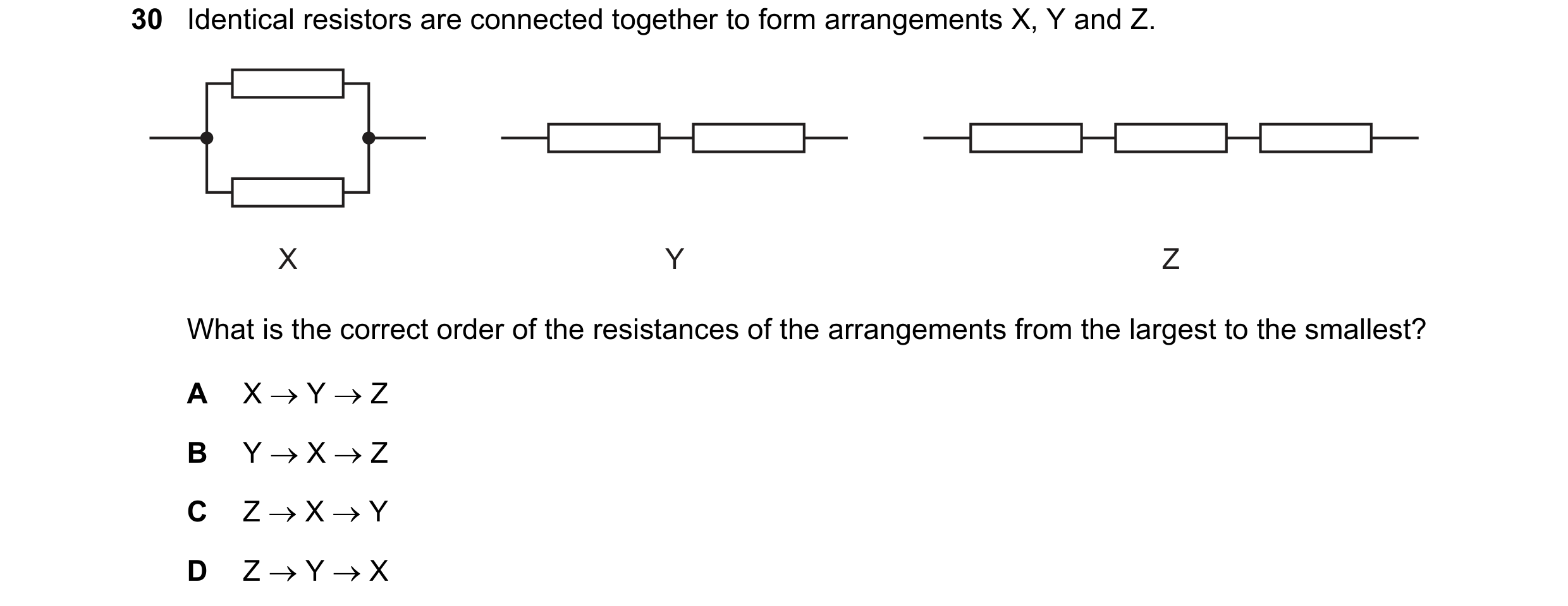
Q30 · Identical resistors are connected together to form arrangements X, Y and Z 0972/21 Oct/Nov 2019
30 Identical resistors are connected together to form arrangements X, Y and Z. X Y Z What is the correct order of the resistances of the arrangements from the largest to the smallest? A X → Y → Z B Y → X → Z C Z → X → Y D Z → Y → X
1 marks
Answer: D
This question in 0972/21 Oct/Nov 2019
Q31 · A circuit contains a cell of electromotive force (e.m.f.) 2.0 V, three resistors, three… 0972/21 Oct/Nov 2019
31 A circuit contains a cell of electromotive force (e.m.f.) 2.0 V, three resistors, three ammeters and two voltmeters. One ammeter is labelled P and one voltmeter is labelled Q. The readings on the other two ammeters and on the other voltmeter are shown. 2.0 V 2.0 A A 0.50 A A A V P 0.50 V V Q What is the reading on ammeter P and what is the reading on voltmeter Q? reading on P / A reading on Q / V A 1.5 1.5 B 1.5 2.5 C 2.5 1.5 D 2.5 2.5
1 marks
Answer: A
This question in 0972/21 Oct/Nov 2019
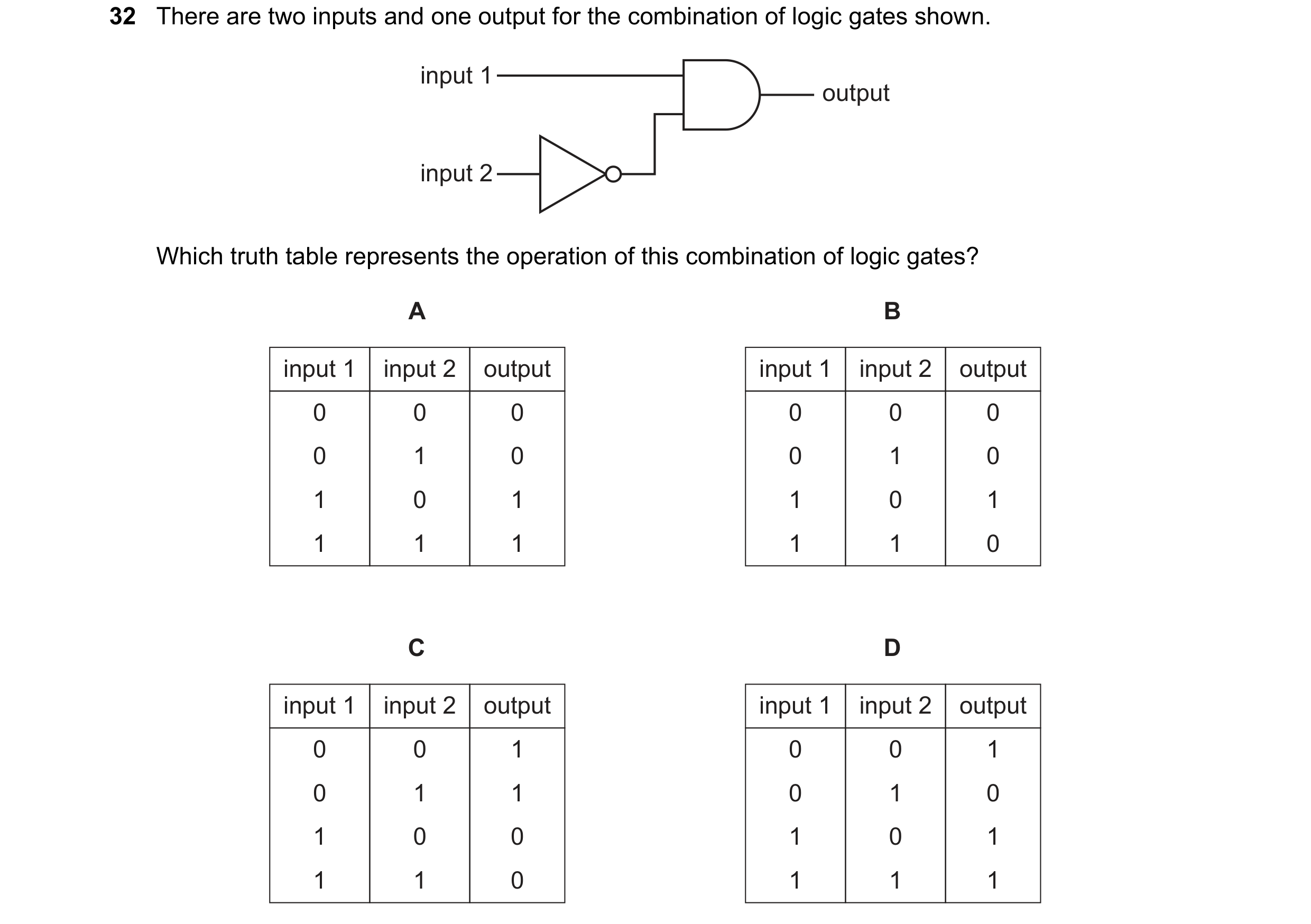
Q32 · There are two inputs and one output for the combination of logic gates shown 0972/21 Oct/Nov 2019
32 There are two inputs and one output for the combination of logic gates shown. input 1 output input 2 Which truth table represents the operation of this combination of logic gates? A B input 1 input 2 output input 1 input 2 output 0 0 0 0 0 0 0 1 0 0 1 0 1 0 1 1 0 1 1 1 1 1 1 0 C D input 1 input 2 output input 1 input 2 output 0 0 1 0 0 1 0 1 1 0 1 0 1 0 0 1 0 1 1 1 0 1 1 1
1 marks
Answer: B
This question in 0972/21 Oct/Nov 2019
Q33 · Where must a fuse be connected in a mains electric circuit? 0972/21 Oct/Nov 2019
33 Where must a fuse be connected in a mains electric circuit? A the earth wire only B the live wire only C the neutral wire only D the live wire and the earth wire
1 marks
Answer: B
This question in 0972/21 Oct/Nov 2019
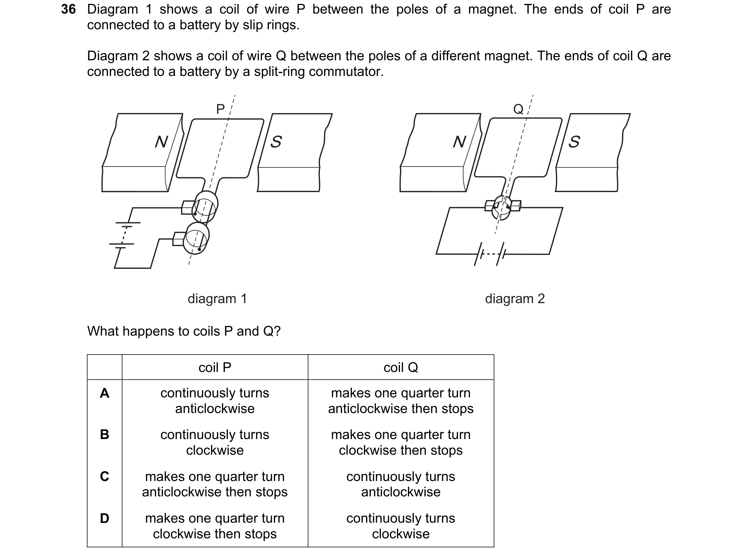
Q34 · A coil of wire P between the poles of a magnet 0972/21 Oct/Nov 2019
36 Diagram 1 shows a coil of wire P between the poles of a magnet. The ends of coil P are connected to a battery by slip rings. Diagram 2 shows a coil of wire Q between the poles of a different magnet. The ends of coil Q are connected to a battery by a split-ring commutator. P Q N S N S diagram 1 diagram 2 What happens to coils P and Q? coil P coil Q A continuously turns makes one quarter turn anticlockwise anticlockwise then stops B continuously turns makes one quarter turn clockwise clockwise then stops C makes one quarter turn continuously turns anticlockwise then stops anticlockwise D makes one quarter turn continuously turns clockwise then stops clockwise
1 marks
Answer: C
This question in 0972/21 Oct/Nov 2019
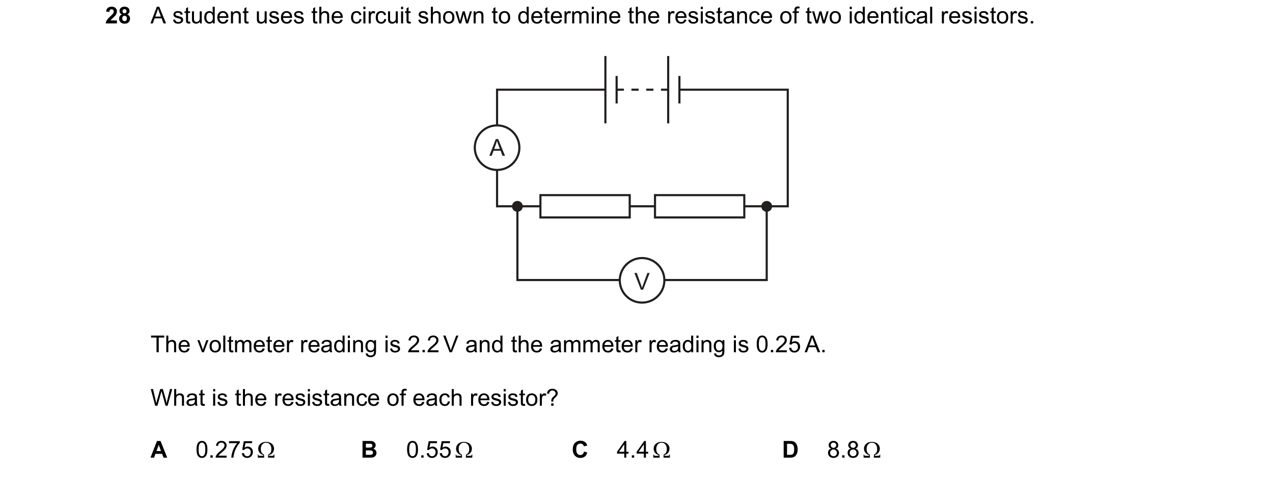
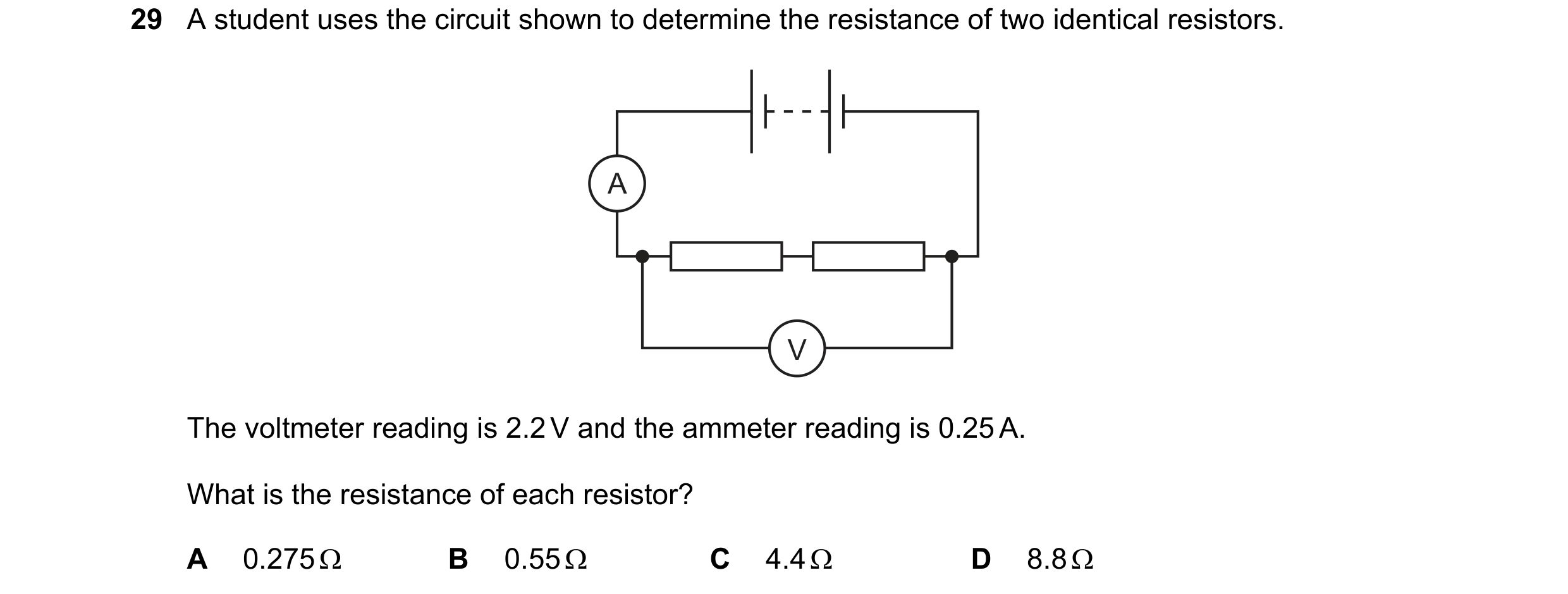
Q35 · A student uses the circuit shown to determine the resistance of two identical resistors 0972/21 May/June 2020
28 A student uses the circuit shown to determine the resistance of two identical resistors. A V The voltmeter reading is 2.2 V and the ammeter reading is 0.25 A. What is the resistance of each resistor? A 0.275 Ω B 0.55 Ω C 4.4 Ω D 8.8 Ω
1 marks
Answer: C
This question in 0972/21 May/June 2020
Q36 · The diagram shows an incomplete circuit 0972/21 May/June 2020
30 The diagram shows an incomplete circuit. The temperature and light levels around the circuit remain unchanged. P Q A Four electrical components are connected in turn across PQ. The cell is reversed and the four electrical components are connected again in turn across PQ. For which component is there a significant change in the magnitude of the current? A diode B light-dependent resistor C resistor D thermistor
1 marks
Answer: A
This question in 0972/21 May/June 2020
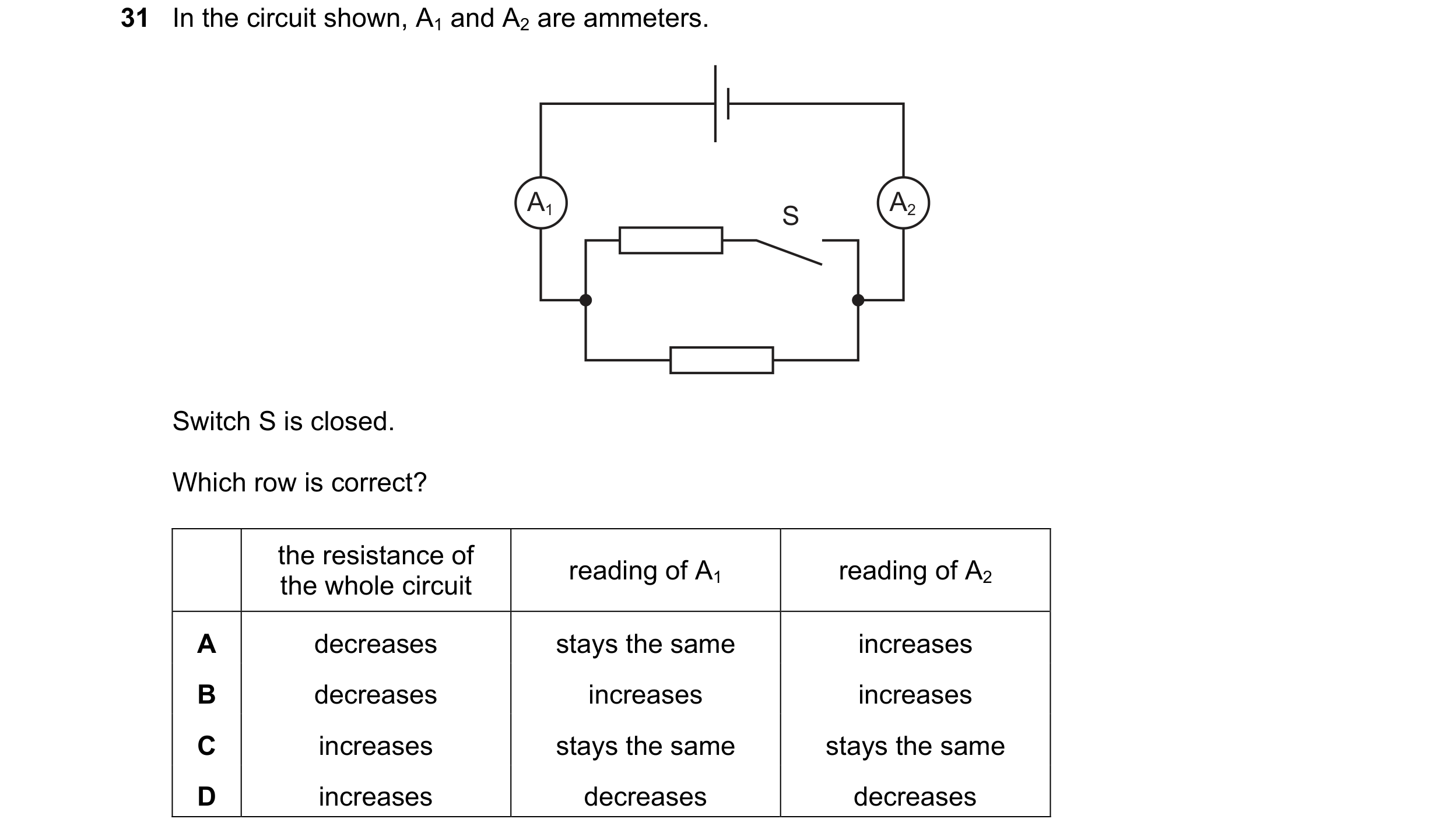
Q37 · In the circuit shown, A1 and A2 are ammeters 0972/21 May/June 2020
31 In the circuit shown, A1 and A2 are ammeters. A1 A2 S Switch S is closed. Which row is correct? the resistance of reading of A1 reading of A2 the whole circuit A decreases stays the same increases B decreases increases increases C increases stays the same stays the same D increases decreases decreases
1 marks
Answer: B
This question in 0972/21 May/June 2020
Q38 · Which symbol represents an OR gate? 0972/21 May/June 2020
32 Which symbol represents an OR gate? A B C D
1 marks
Answer: A
This question in 0972/21 May/June 2020
Q39 · A digital circuit consists of two logic gates 0972/21 May/June 2020
33 A digital circuit consists of two logic gates. When the input to the circuit is 1 and 1, the output is 0. 1 digital input 0 output circuit 1 Which combination of logic gates gives this result? A B C D
1 marks
Answer: C
This question in 0972/21 May/June 2020
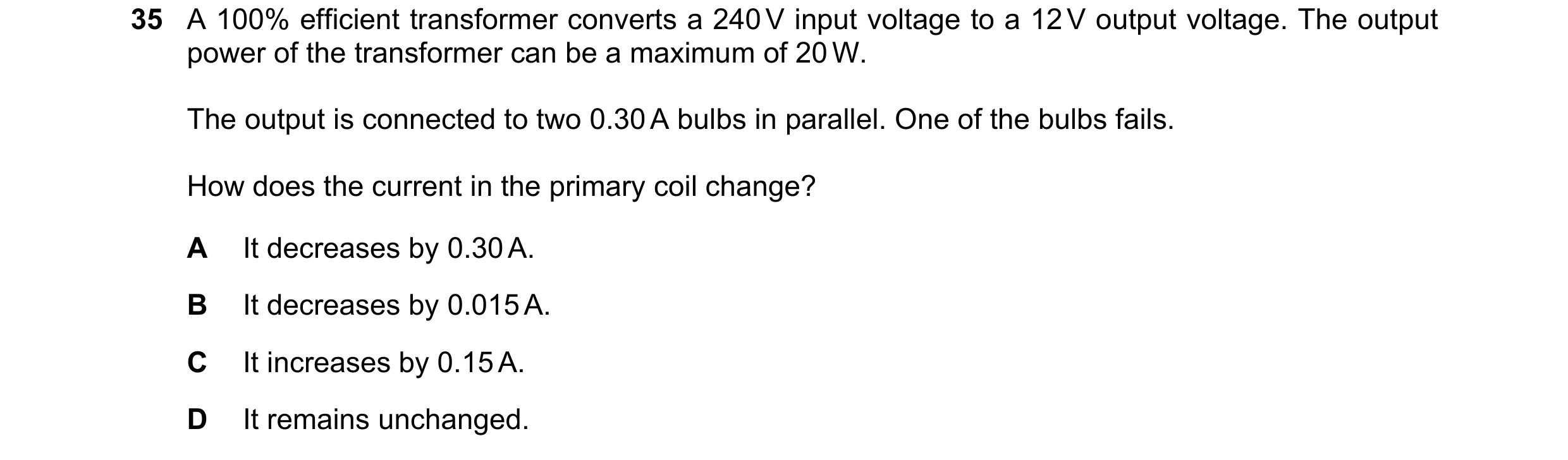
Q40 · A 100% efficient transformer converts a 240 V input voltage to a 12 V output voltage 0972/21 May/June 2020
35 A 100% efficient transformer converts a 240 V input voltage to a 12 V output voltage. The output power of the transformer can be a maximum of 20 W. The output is connected to two 0.30 A bulbs in parallel. One of the bulbs fails. How does the current in the primary coil change? A It decreases by 0.30 A. B It decreases by 0.015 A. C It increases by 0.15 A. D It remains unchanged.
1 marks
Answer: B
This question in 0972/21 May/June 2020
Q41 · Cables transmit electrical power from the output of the transformer at a power station to… 0972/21 May/June 2020
36 Cables transmit electrical power from the output of the transformer at a power station to the input of the transformer at a substation. cables output input transformer at transformer at power station substation The power at the output of the transformer at the power station is 400 MW. Which situation delivers the most power to the input of the transformer at the substation? potential difference at power station transformer diameter of cables output / kV A 200 large B 200 small C 400 large D 400 small
1 marks
Answer: C
This question in 0972/21 May/June 2020
Q42 · A student uses the circuit shown to determine the resistance of two identical resistors 0972/22 May/June 2020
29 A student uses the circuit shown to determine the resistance of two identical resistors. A V The voltmeter reading is 2.2 V and the ammeter reading is 0.25 A. What is the resistance of each resistor? A 0.275 Ω B 0.55 Ω C 4.4 Ω D 8.8 Ω
1 marks
Answer: C
This question in 0972/22 May/June 2020
Q43 · The circuit shown contains five lamps J, K, L, M and N 0972/22 May/June 2020
31 The circuit shown contains five lamps J, K, L, M and N. All the lamps are glowing. lamp L lamp K lamp J lamp N lamp M One lamp is removed and two other lamps go out. Which lamp is removed? A lamp J B lamp K C lamp L D lamp M
1 marks
Answer: A
This question in 0972/22 May/June 2020
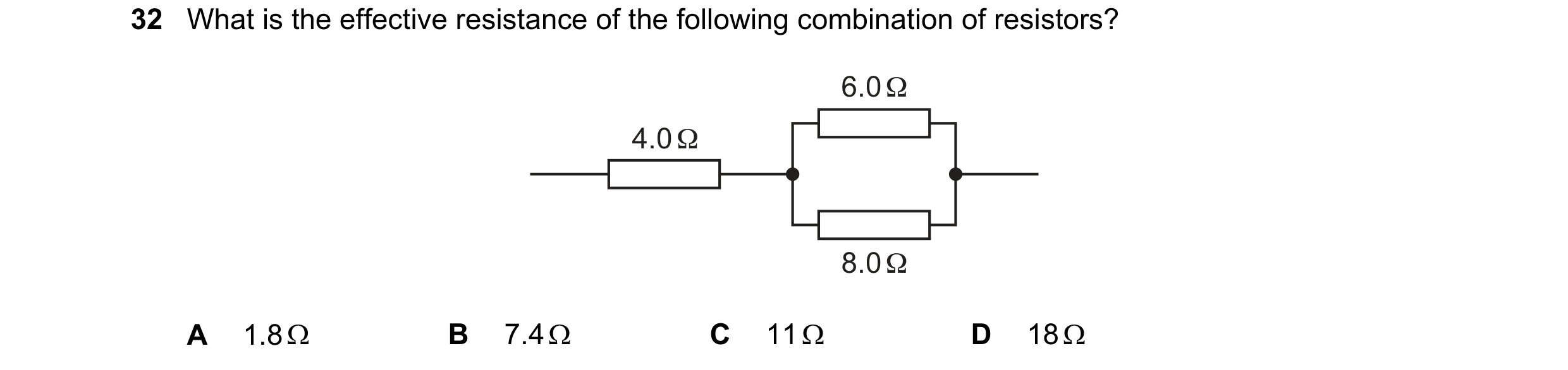
Q44 · What is the effective resistance of the following combination of resistors? 0972/22 May/June 2020
32 What is the effective resistance of the following combination of resistors? 6.0 Ω 4.0 Ω 8.0 Ω A 1.8 Ω B 7.4 Ω C 11 Ω D 18 Ω
1 marks
Answer: B
This question in 0972/22 May/June 2020
Q45 · Which symbol represents a NAND gate? 0972/22 May/June 2020
33 Which symbol represents a NAND gate? A B C D
1 marks
Answer: B
This question in 0972/22 May/June 2020
Q46 · The diagram shows a circuit used to switch on a heater when the temperature drops below a… 0972/22 May/June 2020
34 The diagram shows a circuit used to switch on a heater when the temperature drops below a certain value. X Y Which row shows the components that should be connected at X and at Y? X Y A B C D
1 marks
Answer: B
This question in 0972/22 May/June 2020
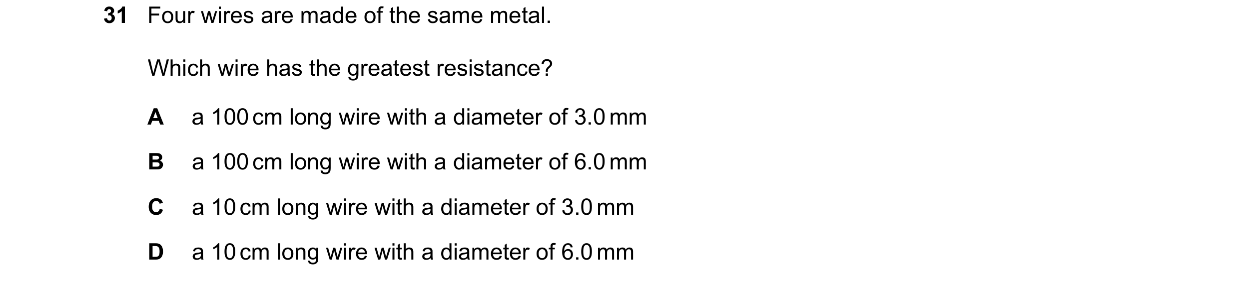
Q47 · Four wires are made of the same metal 0972/21 Oct/Nov 2020
31 Four wires are made of the same metal. Which wire has the greatest resistance? A a 100 cm long wire with a diameter of 3.0 mm B a 100 cm long wire with a diameter of 6.0 mm C a 10 cm long wire with a diameter of 3.0 mm D a 10 cm long wire with a diameter of 6.0 mm
1 marks
Answer: A
This question in 0972/21 Oct/Nov 2020
Q48 · In which circuit is there just a single lamp lit? 0972/21 Oct/Nov 2020
32 In which circuit is there just a single lamp lit? A B C D
1 marks
Answer: C
This question in 0972/21 Oct/Nov 2020
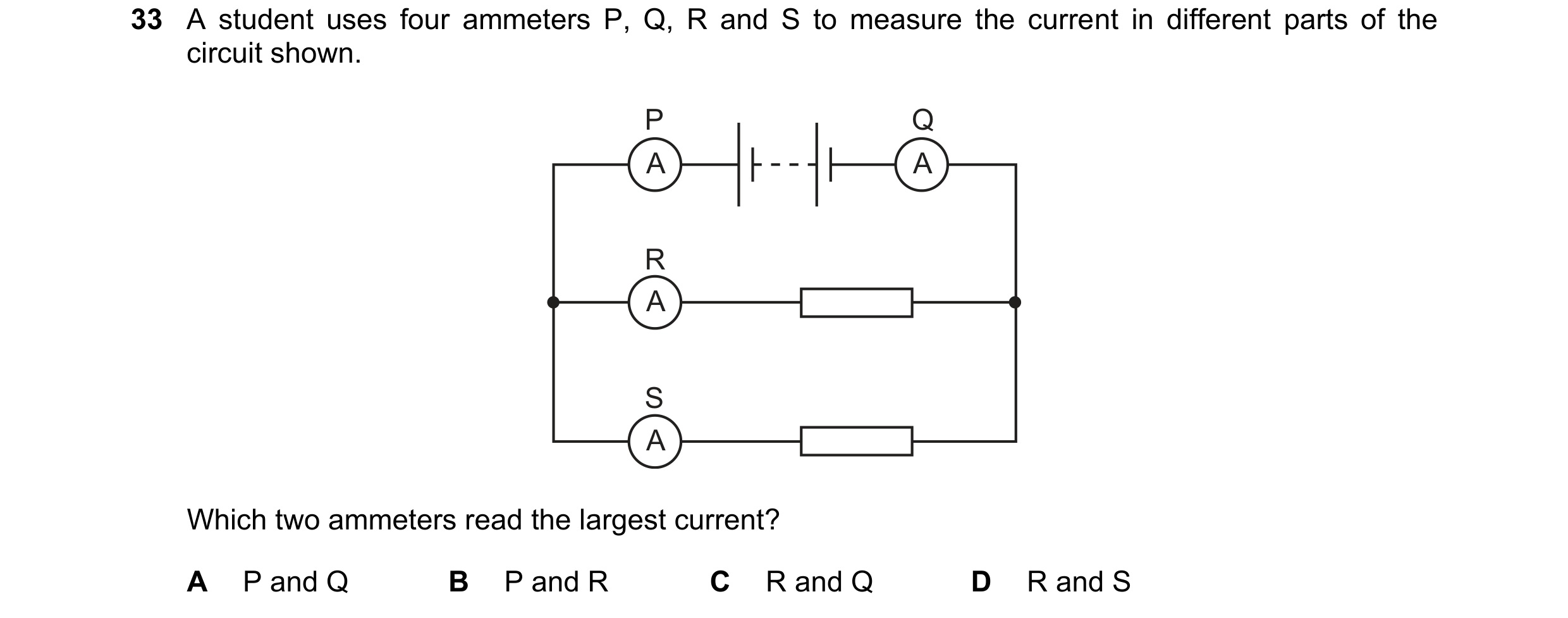
Q49 · A student uses four ammeters P, Q, R and S to measure the current in different parts of… 0972/21 Oct/Nov 2020
33 A student uses four ammeters P, Q, R and S to measure the current in different parts of the circuit shown. P Q A A R A S A Which two ammeters read the largest current? A P and Q B P and R C R and Q D R and S
1 marks
Answer: A
This question in 0972/21 Oct/Nov 2020
Q50 · Which combination of logic gates gives the truth table shown? 0972/21 Oct/Nov 2020
34 Which combination of logic gates gives the truth table shown? inputs output X Y Z 0 0 1 0 1 1 1 0 1 1 1 0 A B X X Z Z Y Y C D X X Z Z Y Y
1 marks
Answer: B
This question in 0972/21 Oct/Nov 2020
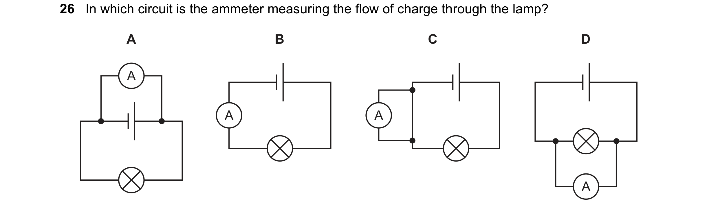
Q51 · In which circuit is the ammeter measuring the flow of charge through the lamp? 0972/21 Oct/Nov 2021
26 In which circuit is the ammeter measuring the flow of charge through the lamp? A B C D A A A A
1 marks
Answer: B
This question in 0972/21 Oct/Nov 2021
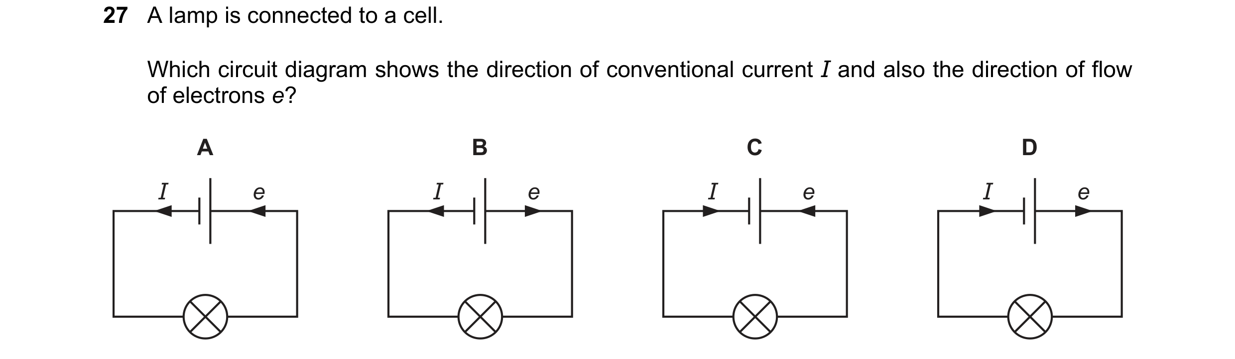
Q52 · A lamp is connected to a cell 0972/21 Oct/Nov 2021
27 A lamp is connected to a cell. Which circuit diagram shows the direction of conventional current I and also the direction of flow of electrons e? A B C D I e I e I e I e
1 marks
Answer: C
This question in 0972/21 Oct/Nov 2021
Q53 · The diagram shows a circuit containing two resistors of resistance 1.0 and 2.0 0972/21 Oct/Nov 2021
28 The diagram shows a circuit containing two resistors of resistance 1.0 and 2.0 . A voltmeter is connected across the 1.0 resistor by connecting P to X. The reading on the voltmeter is 6.0 V. 1.0 Ω X 2.0 Ω Y P V P is moved to point Y in the circuit. What is the new reading on the voltmeter? A 3.0 V B 6.0 V C 12 V D 18 V
1 marks
Answer: D
This question in 0972/21 Oct/Nov 2021
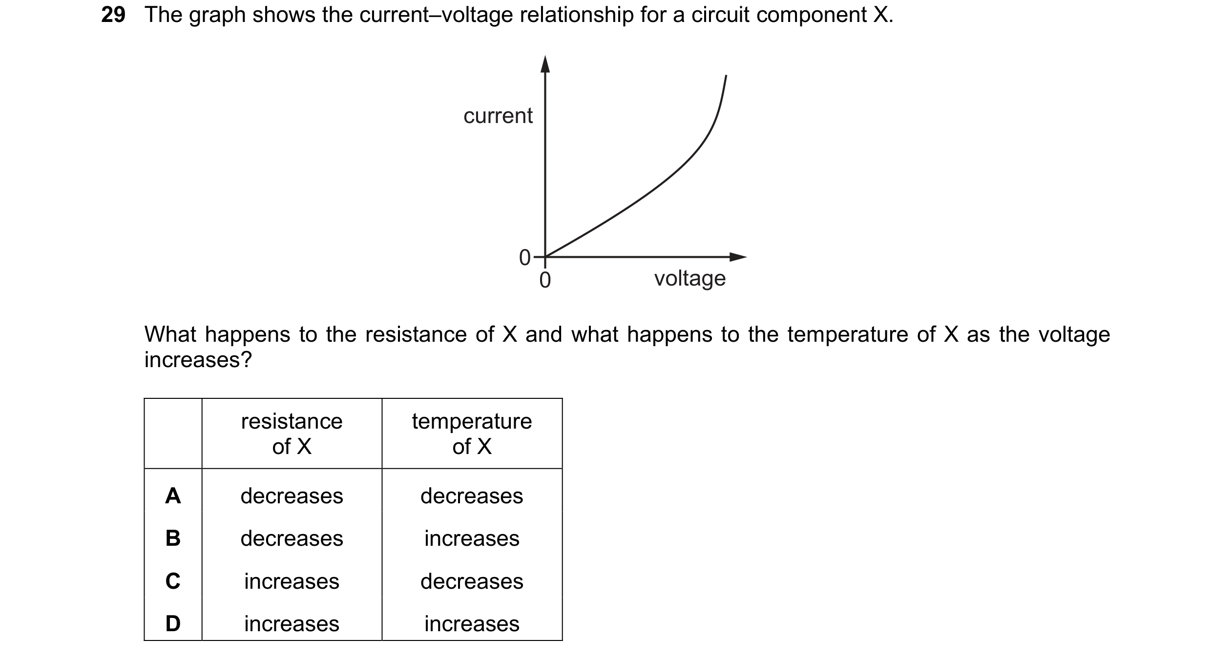
Q54 · The graph shows the current–voltage relationship for a circuit component X 0972/21 Oct/Nov 2021
29 The graph shows the current–voltage relationship for a circuit component X. current 0 0 voltage What happens to the resistance of X and what happens to the temperature of X as the voltage increases? resistance temperature of X of X A decreases decreases B decreases increases C increases decreases D increases increases
1 marks
Answer: B
This question in 0972/21 Oct/Nov 2021
Q55 · The diagrams show pairs of circuits containing logic gates 0972/21 Oct/Nov 2021
30 The diagrams show pairs of circuits containing logic gates. In which diagram does the lower circuit of the pair behave differently from the upper circuit? A B C D
1 marks
Answer: D
This question in 0972/21 Oct/Nov 2021
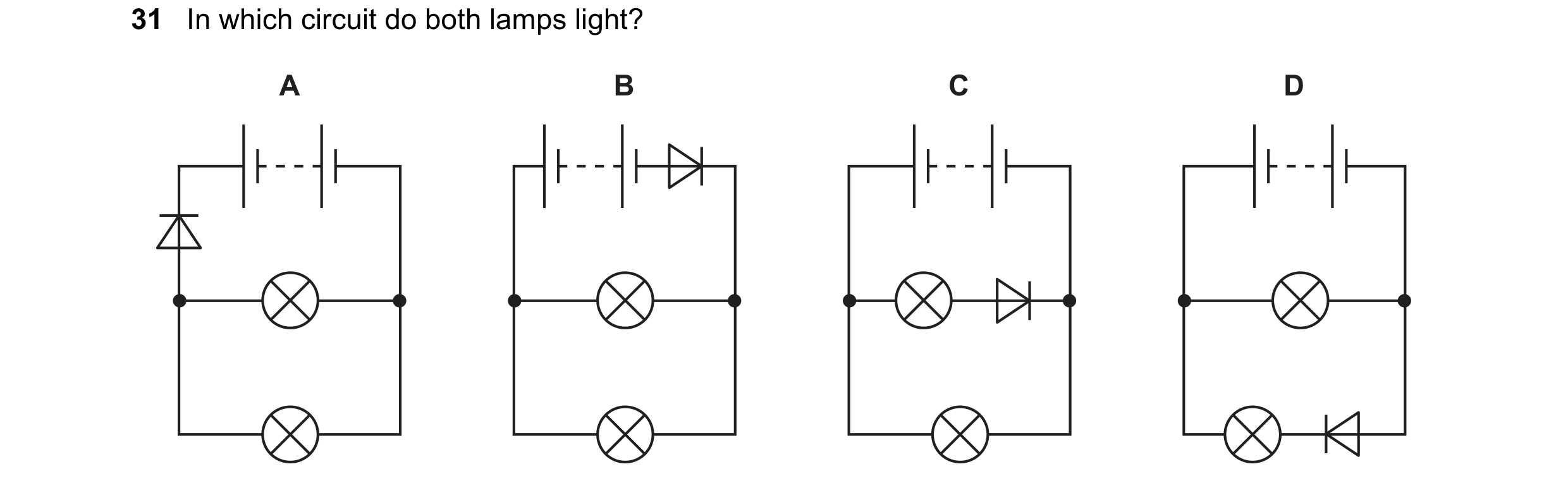
Q56 · In which circuit do both lamps light? 0972/21 Oct/Nov 2021
31 In which circuit do both lamps light? A B C D
1 marks
Answer: C
This question in 0972/21 Oct/Nov 2021
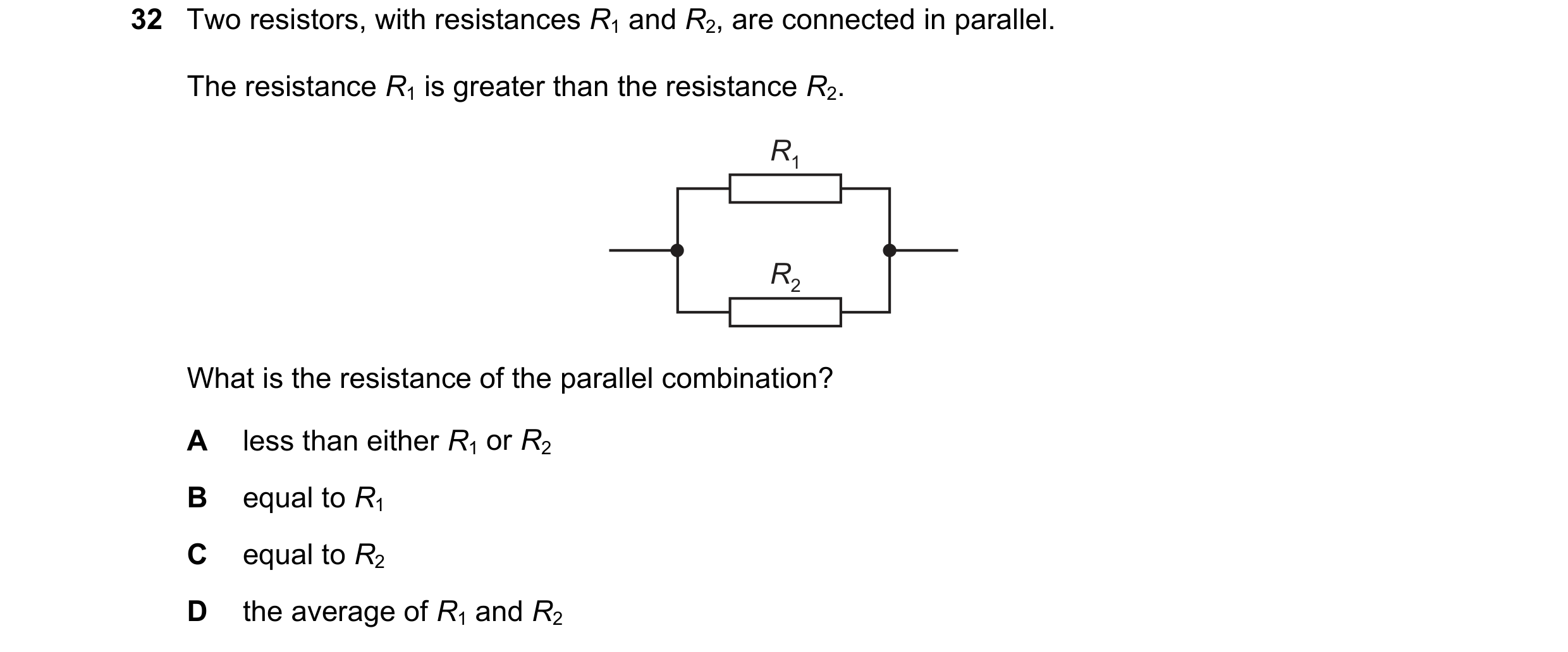
Q57 · Two resistors, with resistances R1 and R2, are connected in parallel 0972/21 Oct/Nov 2021
32 Two resistors, with resistances R1 and R2, are connected in parallel. The resistance R1 is greater than the resistance R2. R1 R2 What is the resistance of the parallel combination? A less than either R1 or R2 B equal to R1 C equal to R2 D the average of R1 and R2
1 marks
Answer: A
This question in 0972/21 Oct/Nov 2021
Q58 · The metal cases of electrical appliances are connected to an earth wire 0972/21 Oct/Nov 2021
33 The metal cases of electrical appliances are connected to an earth wire. Which statement is not correct? A The live wire may become loose and touch the metal case. B If the metal case becomes live, the earth wire conducts current to the ground. C The earth wire needs to have a high resistance. D Earthing metal cases helps prevent a person from receiving an electric shock.
1 marks
Answer: C
This question in 0972/21 Oct/Nov 2021
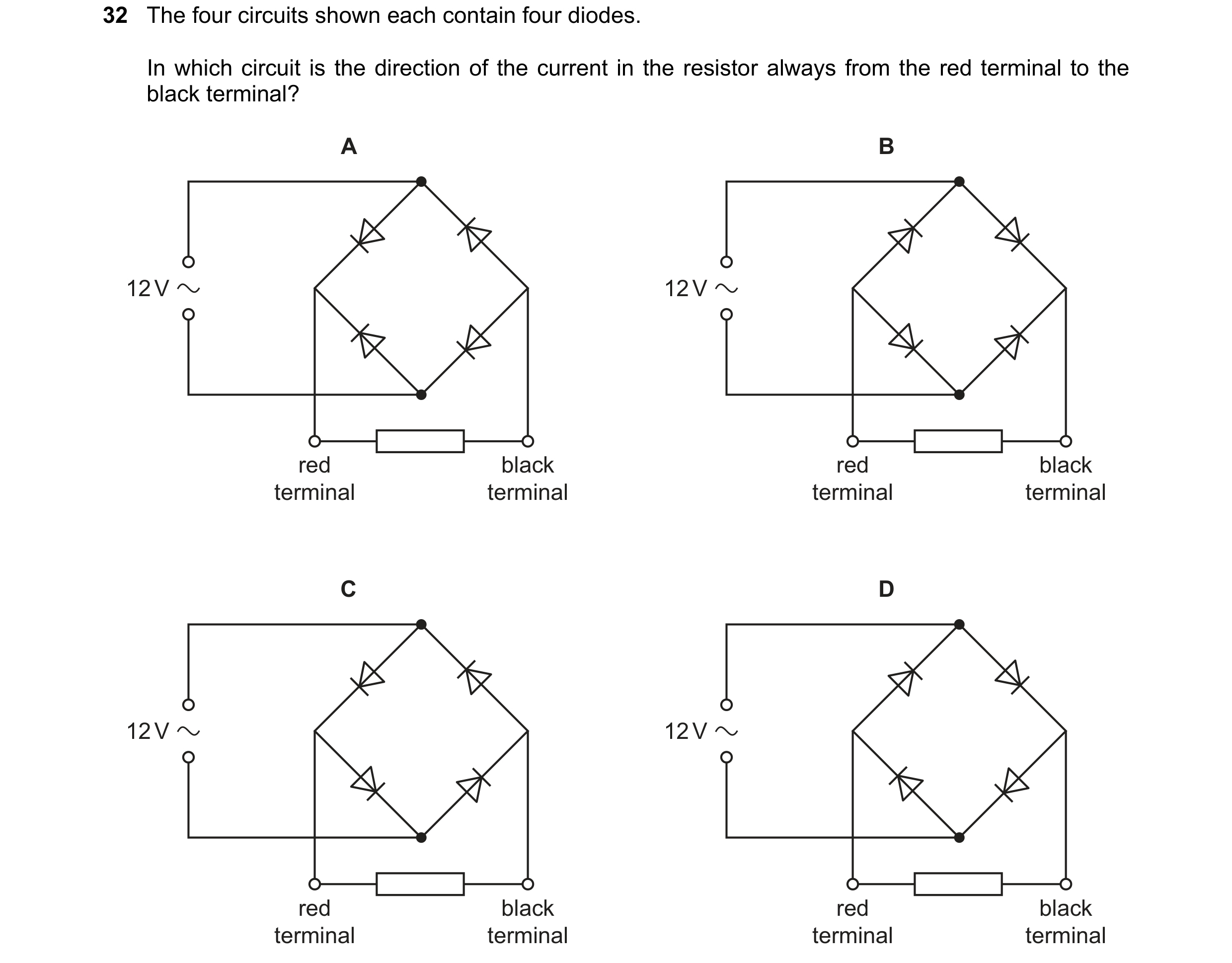
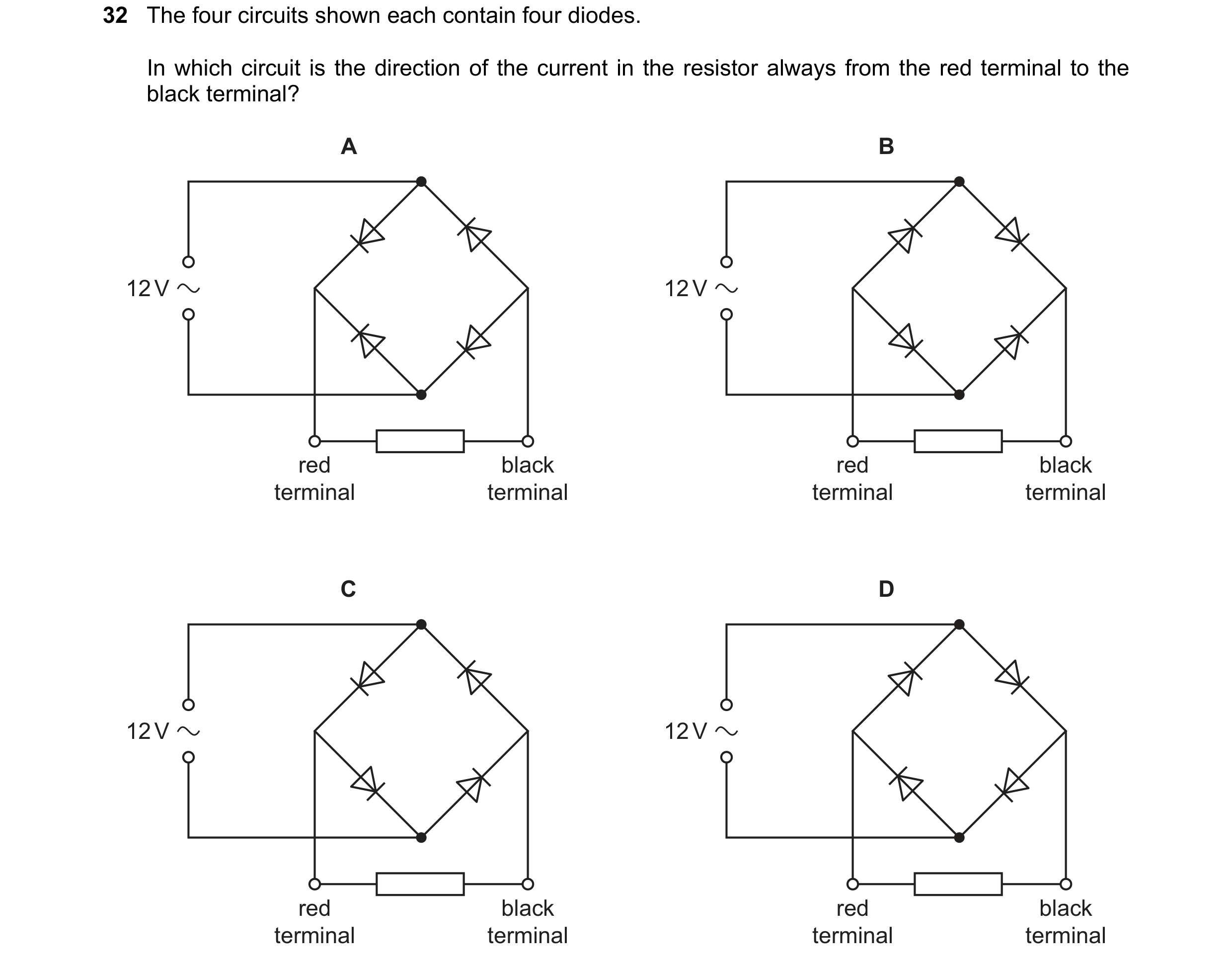
Q59 · The four circuits shown each contain four diodes 0972/21 May/June 2022
32 The four circuits shown each contain four diodes. In which circuit is the direction of the current in the resistor always from the red terminal to the black terminal? A B 12 V 12 V red black red black terminal terminal terminal terminal C D 12 V 12 V red black red black terminal terminal terminal terminal
1 marks
Answer: A
This question in 0972/21 May/June 2022
Q60 · The diagram shows a circuit of six identical lamps connected to a battery 0972/21 May/June 2022
33 The diagram shows a circuit of six identical lamps connected to a battery. S Q P T R U Which lamps are brightest? A P only B Q and R only C S, T and U only D P, Q, R, S, T and U are equally bright
1 marks
Answer: A
This question in 0972/21 May/June 2022
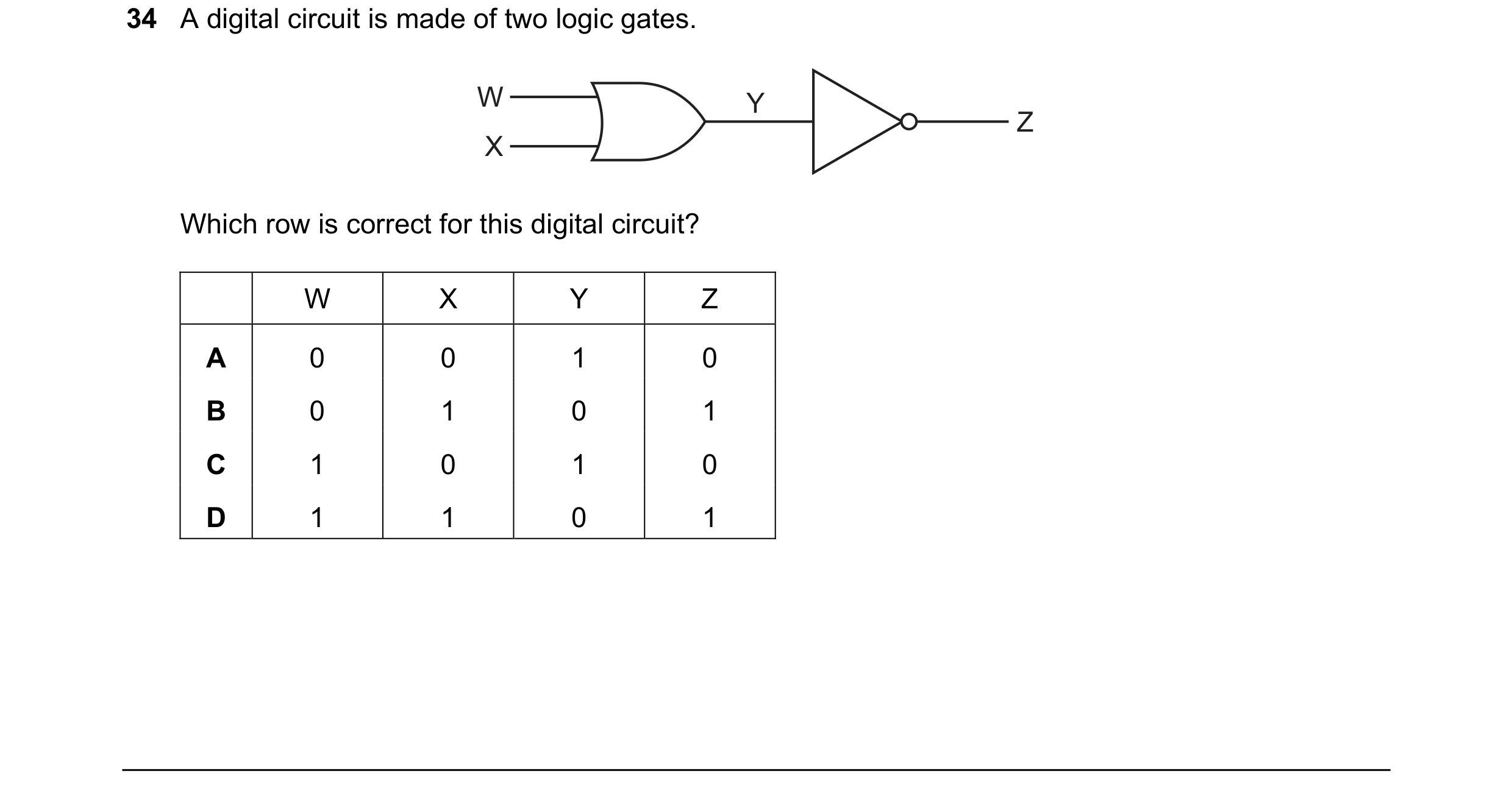
Q61 · A digital circuit is made of two logic gates 0972/21 May/June 2022
34 A digital circuit is made of two logic gates. W Y Z X Which row is correct for this digital circuit? W X Y Z A 0 0 1 0 B 0 1 0 1 C 1 0 1 0 D 1 1 0 1
1 marks
Answer: C
This question in 0972/21 May/June 2022
Q62 · A resistor has a potential difference (p.d.) of 12 V across it and a current of 0.60 A in… 0972/22 May/June 2022
30 A resistor has a potential difference (p.d.) of 12 V across it and a current of 0.60 A in it. What is the resistance of the resistor? A 0.050 B 2.0 C 7.2 D 20
1 marks
Answer: D
This question in 0972/22 May/June 2022
Q63 · There is a current I in a resistor of resistance R for a time t 0972/22 May/June 2022
31 There is a current I in a resistor of resistance R for a time t. The potential difference (p.d.) across the resistor is V. Which equation gives the power P dissipated in the resistor? I V A P = IR B P = It C P = IV D P = t
1 marks
Answer: C
This question in 0972/22 May/June 2022
Q64 · The four circuits shown each contain four diodes 0972/22 May/June 2022
32 The four circuits shown each contain four diodes. In which circuit is the direction of the current in the resistor always from the red terminal to the black terminal? A B 12 V 12 V red black red black terminal terminal terminal terminal C D 12 V 12 V red black red black terminal terminal terminal terminal
1 marks
Answer: A
This question in 0972/22 May/June 2022
Q65 · The diagram shows a battery connected to a potential divider and to two lamps, P and Q 0972/22 May/June 2022
33 The diagram shows a battery connected to a potential divider and to two lamps, P and Q. P X Y Q The slider on the potential divider is moved from end X to end Y of the resistor. Which row shows the effect on the brightness of each lamp? brightness of P brightness of Q A brighter brighter B brighter dimmer C unchanged brighter D unchanged dimmer
1 marks
Answer: C
This question in 0972/22 May/June 2022
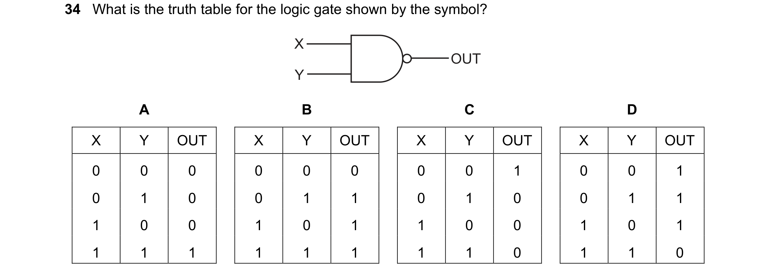
Q66 · What is the truth table for the logic gate shown by the symbol? 0972/22 May/June 2022
34 What is the truth table for the logic gate shown by the symbol? X OUT Y A B C D X Y OUT X Y OUT X Y OUT X Y OUT 0 0 0 0 0 0 0 0 1 0 0 1 0 1 0 0 1 1 0 1 0 0 1 1 1 0 0 1 0 1 1 0 0 1 0 1 1 1 1 1 1 1 1 1 0 1 1 0
1 marks
Answer: D
This question in 0972/22 May/June 2022
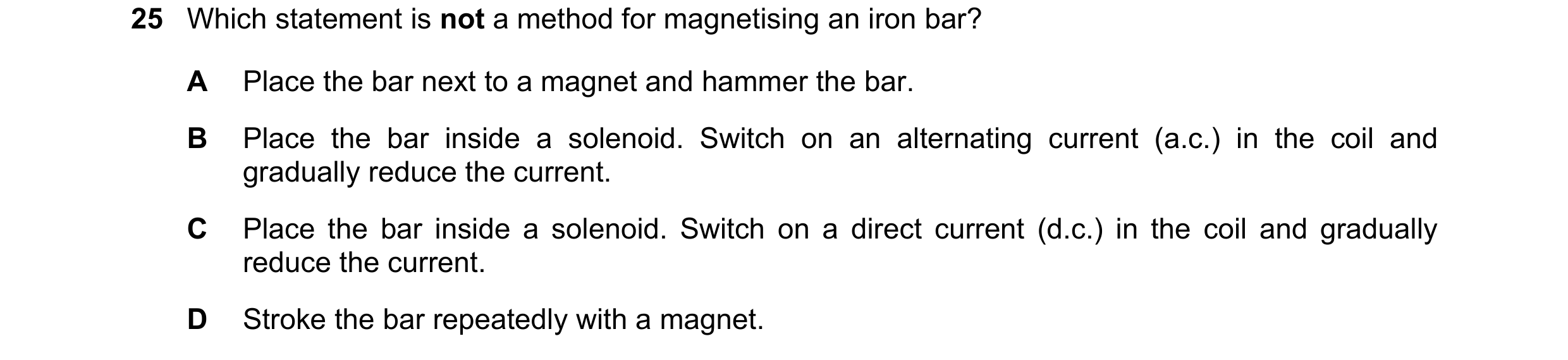
Q67 · Which statement is not a method for magnetising an iron bar? 0972/21 Oct/Nov 2022
25 Which statement is not a method for magnetising an iron bar? A Place the bar next to a magnet and hammer the bar. B Place the bar inside a solenoid. Switch on an alternating current (a.c.) in the coil and gradually reduce the current. C Place the bar inside a solenoid. Switch on a direct current (d.c.) in the coil and gradually reduce the current. D Stroke the bar repeatedly with a magnet.
1 marks
Answer: B
This question in 0972/21 Oct/Nov 2022
Q68 · The diagram shows a circuit containing a variable resistor connected to a variable power… 0972/21 Oct/Nov 2022
26 The diagram shows a circuit containing a variable resistor connected to a variable power supply. power supply The table shows the currents for different values of the potential difference (p.d.) and the resistance. p.d. / V resistance / Ω current 3.6 12 I1 1.2 12 I2 3.6 6 I3 What is the order of the currents from smallest to largest? A I1 → I2 → I3 B I1 → I3 → I2 C I2 → I1 → I3 D I3 → I1 → I2
1 marks
Answer: C
This question in 0972/21 Oct/Nov 2022
Q69 · A lamp rated 12 V, 2.0 A is switched on for one minute 0972/21 Oct/Nov 2022
29 A lamp rated 12 V, 2.0 A is switched on for one minute. How much energy is transferred by the lamp? A 6.0 J B 24 J C 360 J D 1440 J
1 marks
Answer: D
This question in 0972/21 Oct/Nov 2022
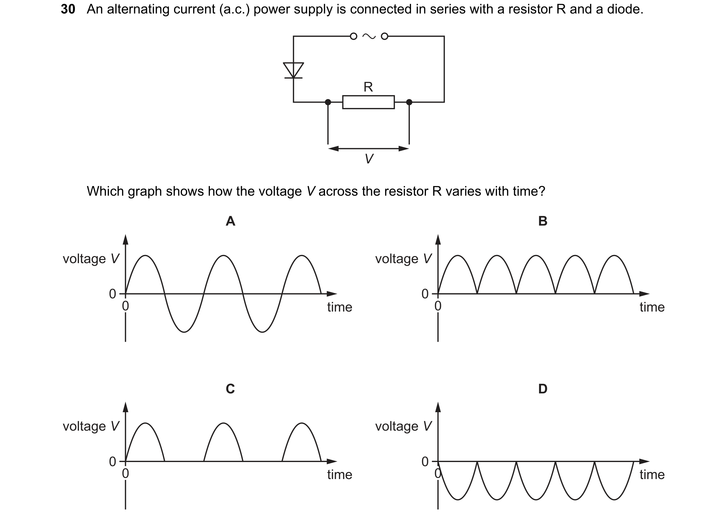
Q70 · An alternating current (a.c.) power supply is connected in series with a resistor R and a… 0972/21 Oct/Nov 2022
30 An alternating current (a.c.) power supply is connected in series with a resistor R and a diode. R V Which graph shows how the voltage V across the resistor R varies with time? A B voltage V voltage V 0 0 0 time 0 time C D voltage V voltage V 0 0 0 time 0 time
1 marks
Answer: C
This question in 0972/21 Oct/Nov 2022
Q71 · A student makes four resistors using different pieces of wire 0972/21 Oct/Nov 2022
31 A student makes four resistors using different pieces of wire. The wires have different diameters and lengths. All the pieces of wire are made of the same material. Which piece of wire will make the resistor with the largest resistance? diameter / mm length / cm A 0.8 10 B 0.8 17 C 2.0 10 D 2.0 17
1 marks
Answer: B
This question in 0972/21 Oct/Nov 2022
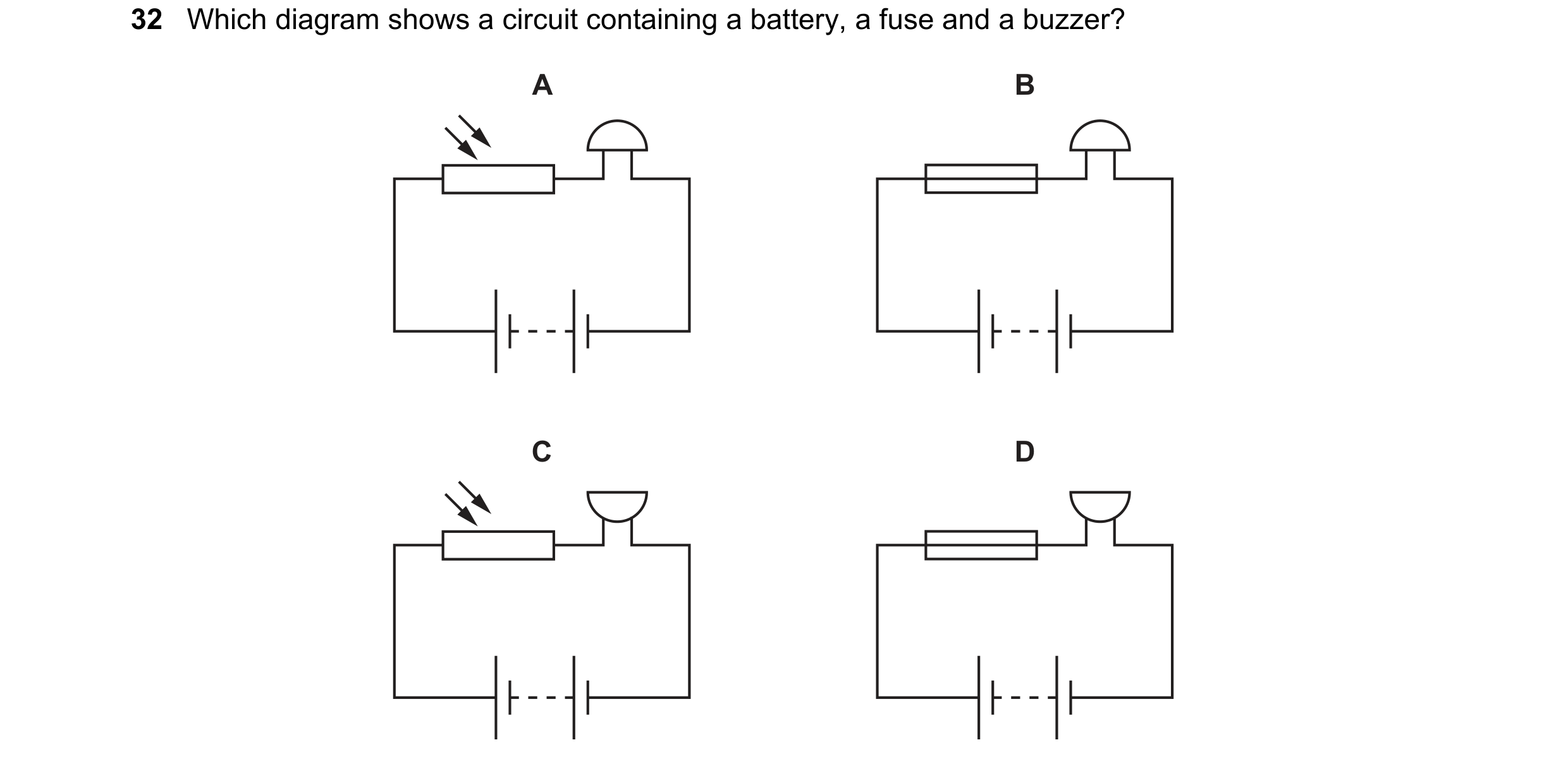
Q72 · Which diagram shows a circuit containing a battery, a fuse and a buzzer? 0972/21 Oct/Nov 2022
32 Which diagram shows a circuit containing a battery, a fuse and a buzzer? A B C D
1 marks
Answer: D
This question in 0972/21 Oct/Nov 2022
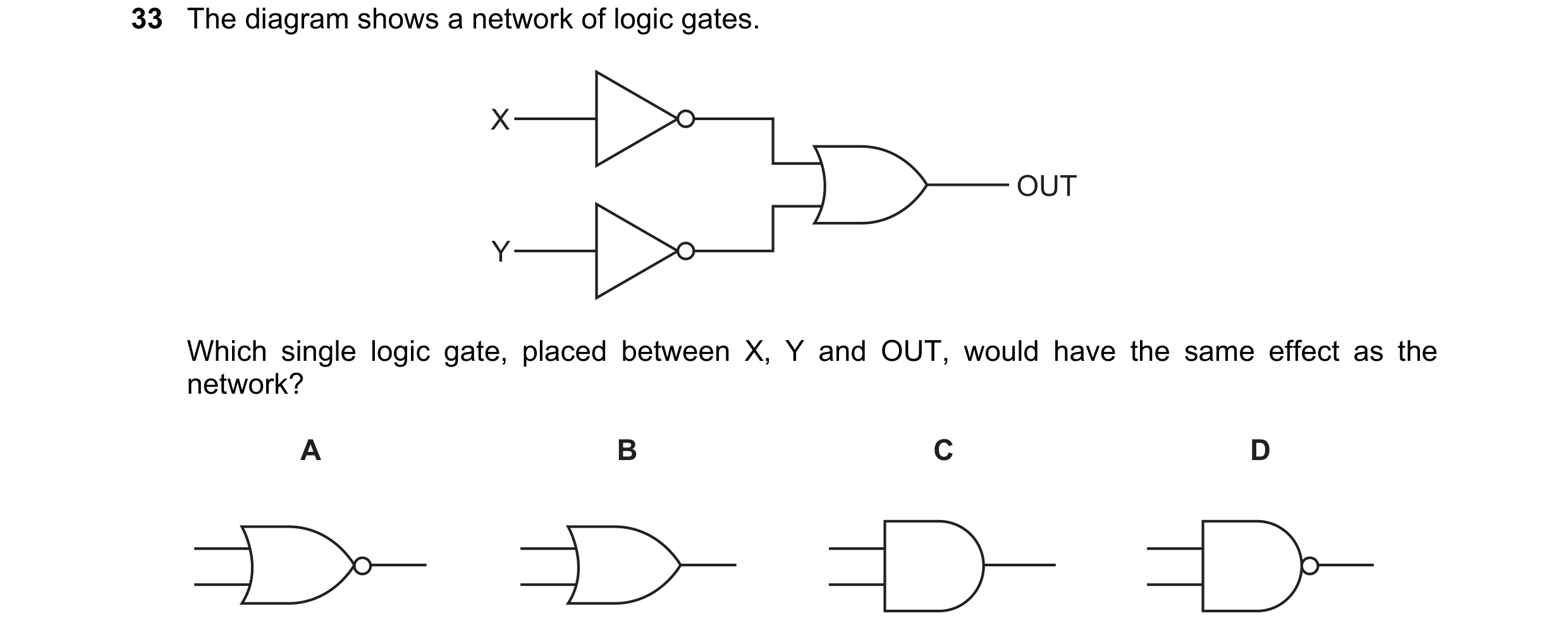
Q73 · The diagram shows a network of logic gates 0972/21 Oct/Nov 2022
33 The diagram shows a network of logic gates. X OUT Y Which single logic gate, placed between X, Y and OUT, would have the same effect as the network? A B C D
1 marks
Answer: D
This question in 0972/21 Oct/Nov 2022
Q74 · The diagram represents a transformer 0972/21 Oct/Nov 2022
34 The diagram represents a transformer. core primary coil Which row shows materials suitable for making the core and the primary coil? core primary coil A iron copper B iron plastic C steel copper D steel plastic
1 marks
Answer: A
This question in 0972/21 Oct/Nov 2022
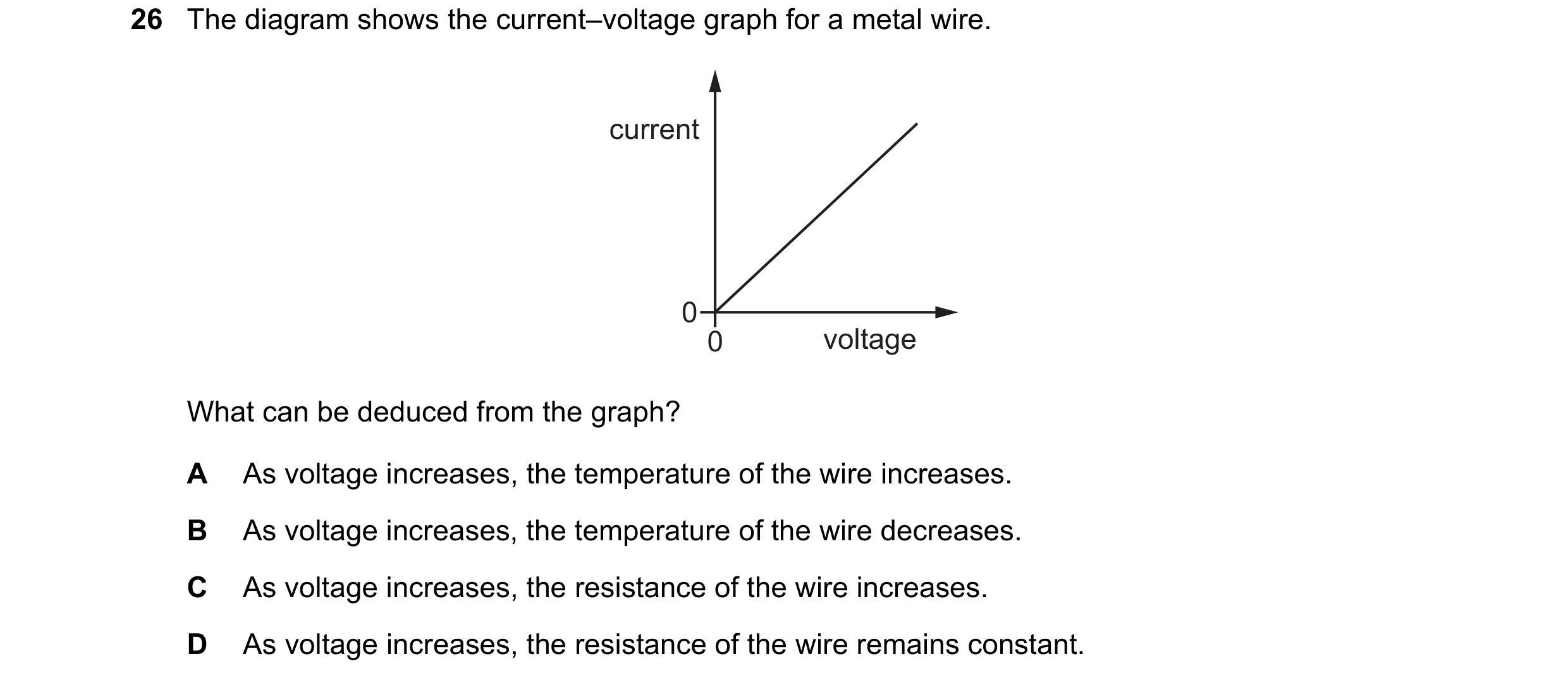
Q75 · The diagram shows the current–voltage graph for a metal wire 0972/21 May/June 2023
26 The diagram shows the current–voltage graph for a metal wire. current 0 0 voltage What can be deduced from the graph? A As voltage increases, the temperature of the wire increases. B As voltage increases, the temperature of the wire decreases. C As voltage increases, the resistance of the wire increases. D As voltage increases, the resistance of the wire remains constant.
1 marks
Answer: D
This question in 0972/21 May/June 2023
Q76 · The circuit diagram shows two identical lamps connected in parallel to a cell 0972/21 May/June 2023
28 The circuit diagram shows two identical lamps connected in parallel to a cell. Three ammeters, X, Y and Z, are also connected in the circuit, as shown. X A Y A Z A Which statement about the current in X is correct? A It is equal to the current in Y and to the current in Z. B It is less than either the current in Y or the current in Z. C It is equal to the sum of the current in Y and the current in Z. D It is equal to the difference between the current in Y and the current in Z.
1 marks
Answer: C
This question in 0972/21 May/June 2023
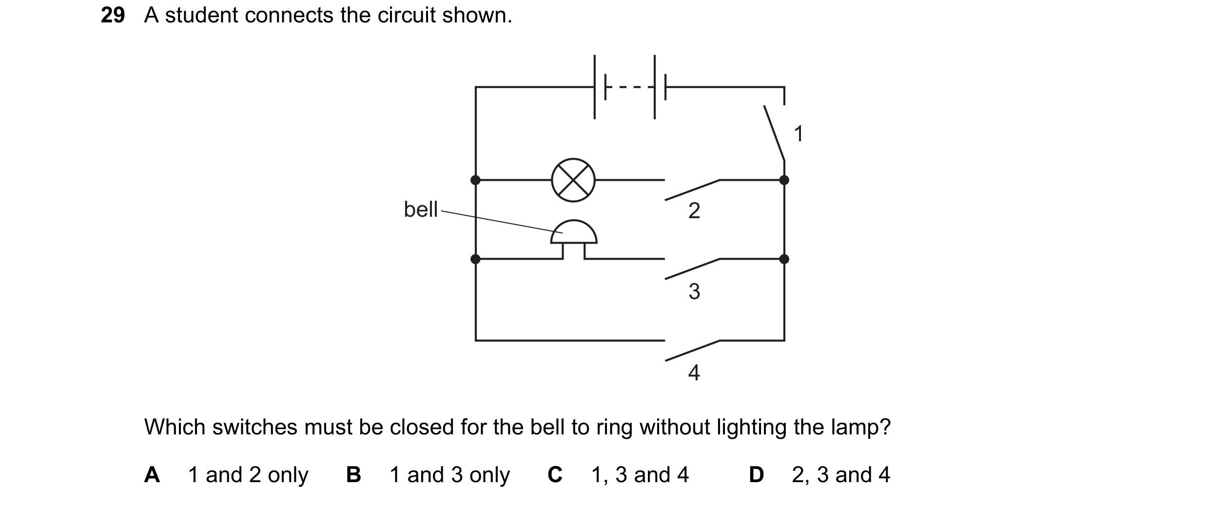
Q77 · A student connects the circuit shown 0972/21 May/June 2023
29 A student connects the circuit shown. 1 bell 2 3 4 Which switches must be closed for the bell to ring without lighting the lamp? A 1 and 2 only B 1 and 3 only C 1, 3 and 4 D 2, 3 and 4
1 marks
Answer: B
This question in 0972/21 May/June 2023
Q78 · Which statement about a transformer is correct? 0972/21 May/June 2023
32 Which statement about a transformer is correct? A There is an alternating current in the iron core from the primary coil to the secondary coil. B An alternating current in the iron core induces an alternating current in the secondary coil. C An alternating current in the primary coil induces a direct current in the secondary coil. D An alternating current in the primary coil induces an alternating voltage across the secondary coil.
1 marks
Answer: D
This question in 0972/21 May/June 2023
Q79 · Which statement about electric current in a conductor is correct? 0972/22 May/June 2023
25 Which statement about electric current in a conductor is correct? A In a d.c. circuit, the electric current gradually decreases along the conductor. B In a d.c. circuit, the free electrons flow back and forth. C In an a.c. circuit, the electric current remains exactly the same all the time. D In an a.c. circuit, the flow of charge changes direction continually.
1 marks
Answer: D
This question in 0972/22 May/June 2023
Q80 · Two lamps are connected in parallel 0972/22 May/June 2023
28 Two lamps are connected in parallel. S1 S2 S3 Which switches must be closed so that both lamps light? A S1 and S2 only B S1 and S3 only C S2 and S3 only D S1, S2 and S3
1 marks
Answer: D
This question in 0972/22 May/June 2023
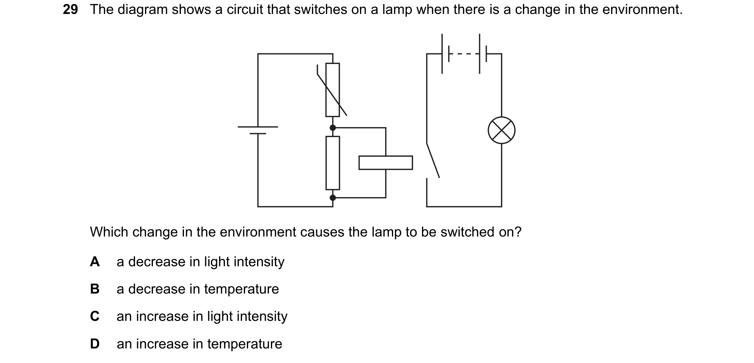
Q81 · The diagram shows a circuit that switches on a lamp when there is a change in the… 0972/22 May/June 2023
29 The diagram shows a circuit that switches on a lamp when there is a change in the environment. Which change in the environment causes the lamp to be switched on? A a decrease in light intensity B a decrease in temperature C an increase in light intensity D an increase in temperature
1 marks
Answer: D
This question in 0972/22 May/June 2023
Q82 · A step-down transformer is 100% efficient 0972/22 May/June 2023
30 A step-down transformer is 100% efficient. It has an input voltage of 240 V a.c. and an output voltage of 60 V a.c. The current in the primary coil is 0.50 A. What is the current in the secondary coil? A 0.13 A B 0.50 A C 2.0 A D 8.0 A
1 marks
Answer: C
This question in 0972/22 May/June 2023
Q83 · In which device is the magnetic effect of a current not used? 0972/22 May/June 2023
32 In which device is the magnetic effect of a current not used? A electromagnet B loudspeaker C potential divider D relay
1 marks
Answer: C
This question in 0972/22 May/June 2023
Q84 · Which statement about a voltmeter is correct? 0972/21 Oct/Nov 2023
26 Which statement about a voltmeter is correct? A It has a scale which is marked in amperes (A). B It must be connected in series in a circuit. C It measures potential difference (p.d.). D It must have three terminals.
1 marks
Answer: C
This question in 0972/21 Oct/Nov 2023
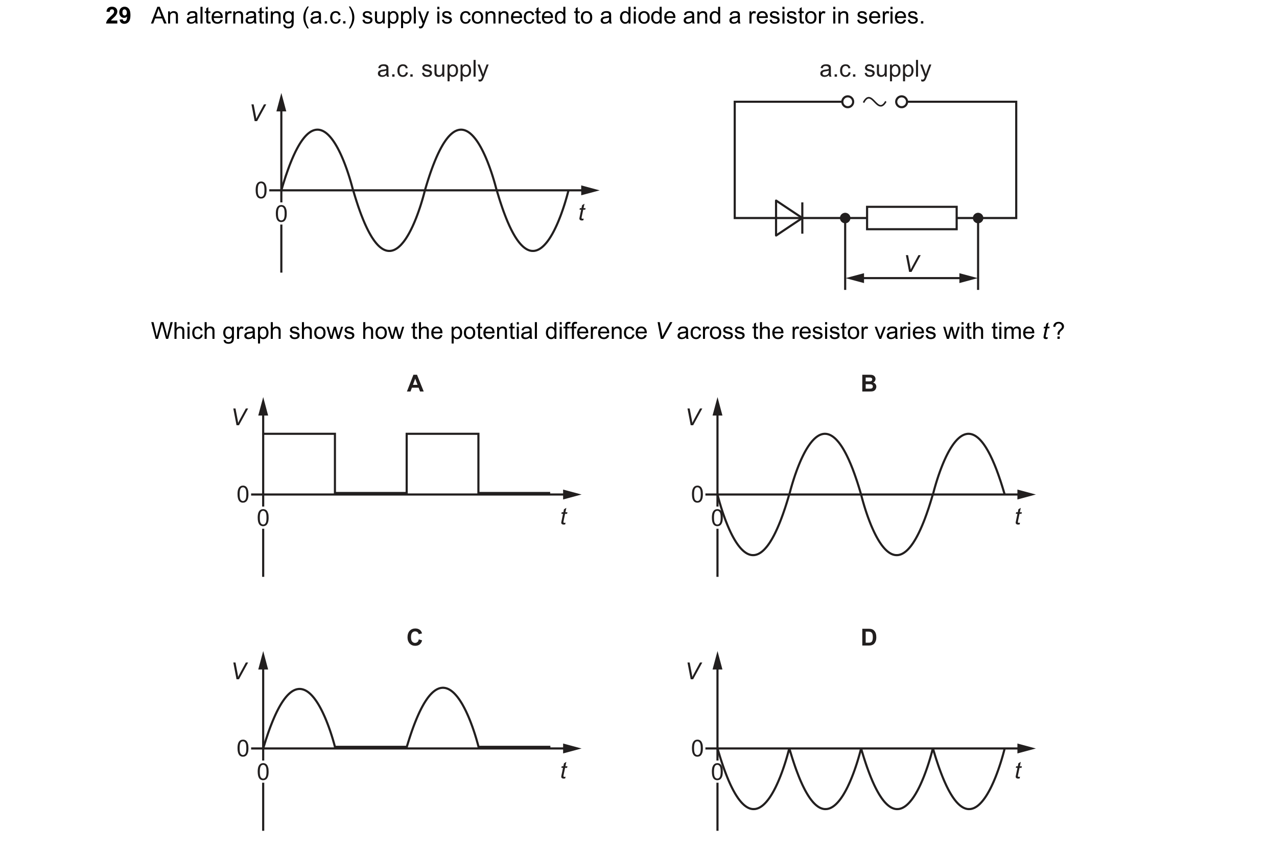
Q85 · An alternating (a.c.) supply is connected to a diode and a resistor in series 0972/21 Oct/Nov 2023
29 An alternating (a.c.) supply is connected to a diode and a resistor in series. a.c. supply a.c. supply V 0 0 t V Which graph shows how the potential difference V across the resistor varies with time t ? A B V V 0 0 0 t 0 t C D V V 0 0 0 t 0 t
1 marks
Answer: C
This question in 0972/21 Oct/Nov 2023
Q86 · The diagram shows a circuit used to switch on a heater when the temperature drops below a… 0972/21 Oct/Nov 2023
30 The diagram shows a circuit used to switch on a heater when the temperature drops below a certain value. X Y Which row shows the components that should be connected at X and at Y? X Y A B C D
1 marks
Answer: B
This question in 0972/21 Oct/Nov 2023
Q87 · A transformer in a computer is used to transform the mains voltage of 240 V to 12 V 0972/21 Oct/Nov 2023
33 A transformer in a computer is used to transform the mains voltage of 240 V to 12 V. The number of turns on the secondary coil is 2000. Which statement about the transformer is correct? A It is a step-down transformer and has 100 turns on its primary coil. B It is a step-down transformer and has 40 000 turns on its primary coil. C It is a step-up transformer and has 100 turns on its primary coil. D It is a step-up transformer and has 40 000 turns on its primary coil.
1 marks
Answer: B
This question in 0972/21 Oct/Nov 2023
Q88 · A student determines the resistance of resistor R 0972/21 May/June 2024
26 A student determines the resistance of resistor R. She uses a circuit including a voltmeter and an ammeter. Which circuit does she use? A B C D V A V V A R R R R A A V
1 marks
Answer: D
This question in 0972/21 May/June 2024
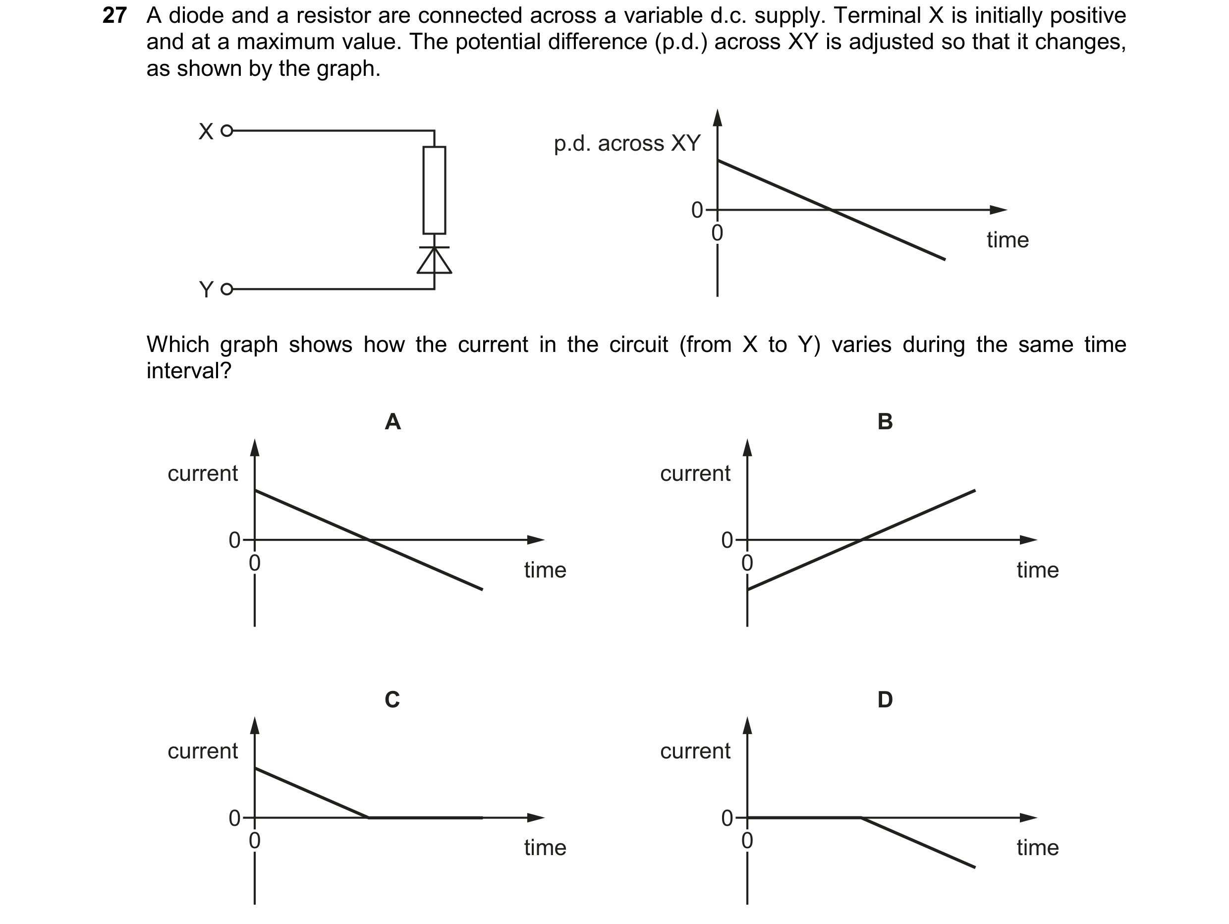
Q89 · A diode and a resistor are connected across a variable d.c 0972/21 May/June 2024
27 A diode and a resistor are connected across a variable d.c. supply. Terminal X is initially positive and at a maximum value. The potential difference (p.d.) across XY is adjusted so that it changes, as shown by the graph. X p.d. across XY 0 0 time Y Which graph shows how the current in the circuit (from X to Y) varies during the same time interval? A B current current 0 0 0 time 0 time C D current current 0 0 0 time 0 time
1 marks
Answer: D
This question in 0972/21 May/June 2024
Q90 · Which types of electric current are in the primary coil and the secondary coil of a… 0972/21 May/June 2024
31 Which types of electric current are in the primary coil and the secondary coil of a step-up transformer? primary secondary coil coil A a.c. a.c. B a.c. d.c. C d.c. a.c. D d.c. d.c.
1 marks
Answer: A
This question in 0972/21 May/June 2024
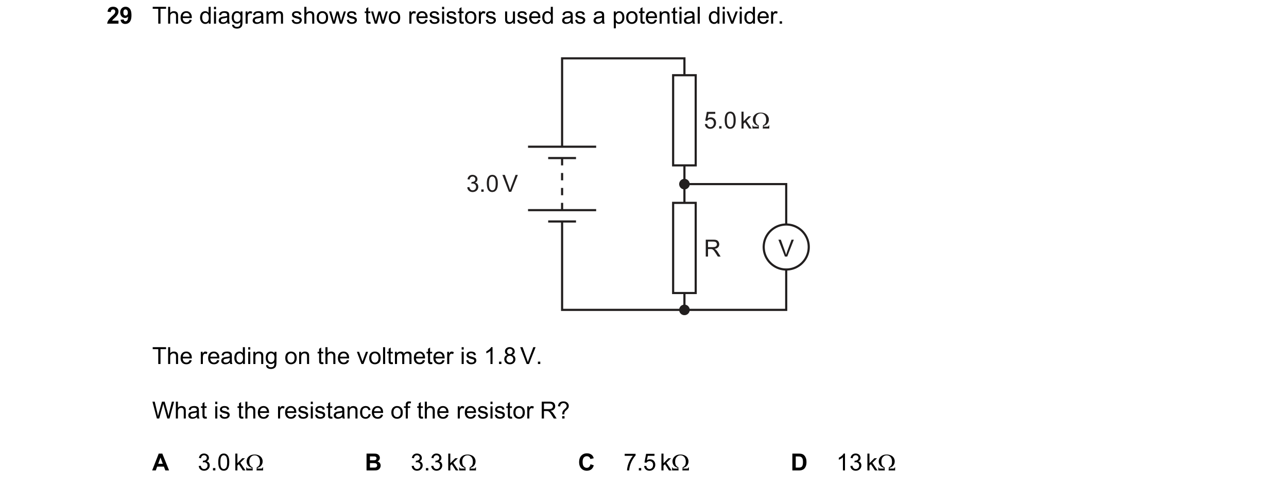
Q91 · The diagram shows two resistors used as a potential divider 0972/22 May/June 2024
29 The diagram shows two resistors used as a potential divider.
The reading on the voltmeter is 1.8 V.
What is the resistance of the resistor R?
A 3.0kQ B 3.3kQ C 7.5kQ D 13kQ
1 marks
Answer: C
This question in 0972/22 May/June 2024
Q92 · Two electrical appliances are connected to the mains supply 0972/22 May/June 2024
30 Two electrical appliances are connected to the mains supply. The cable connected to one appliance includes an earth wire. The cable connected to the second appliance does not need an earth wire. What is a reason for this difference? A One appliance has a metal case, but the other appliance does not. B One appliance is fitted with a fuse, but the other appliance is not. C One appliance is fitted with a switch, but the other appliance is not. D One appliance needs more current than the other appliance.
1 marks
Answer: A
This question in 0972/22 May/June 2024
Q93 · A 24 V power supply and a 100% efficient transformer are used to light a 6.0 V, 12 W lamp 0972/22 May/June 2024
32 A 24 V power supply and a 100% efficient transformer are used to light a 6.0 V, 12 W lamp. What is the current in the power supply? A 0.50 A B 2.0 A C 3.0 A D 8.0 A
1 marks
Answer: A
This question in 0972/22 May/June 2024
Q94 · Which circuit contains a diode connected in series with a fixed resistor? 0972/21 Oct/Nov 2024
28 Which circuit contains a diode connected in series with a fixed resistor? A B C D
1 marks
Answer: C
This question in 0972/21 Oct/Nov 2024
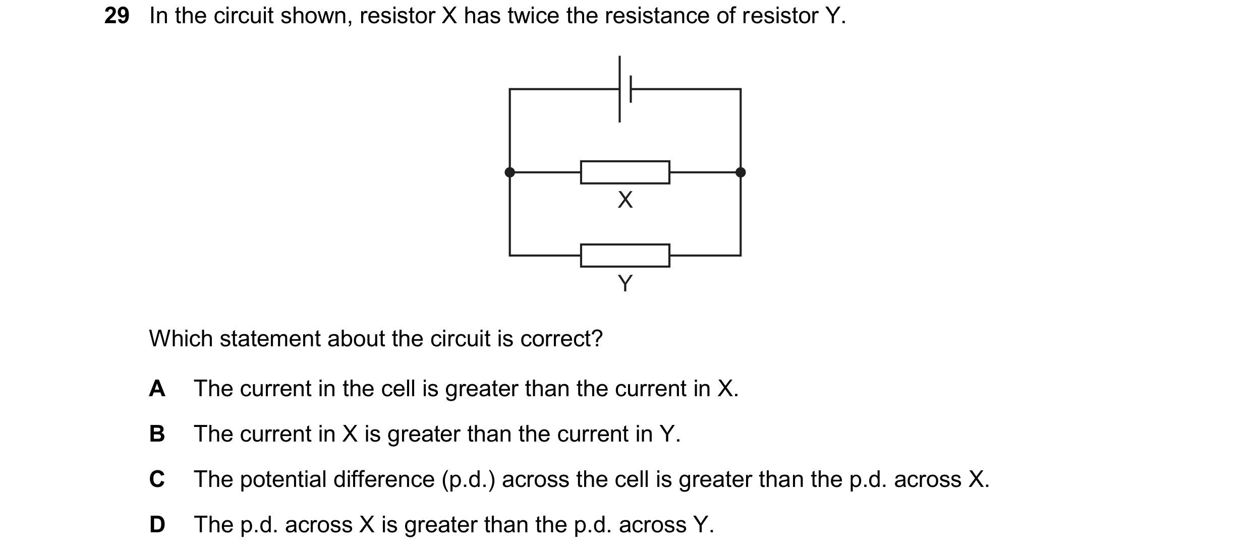
Q95 · In the circuit shown, resistor X has twice the resistance of resistor Y 0972/21 Oct/Nov 2024
29 In the circuit shown, resistor X has twice the resistance of resistor Y. X Y Which statement about the circuit is correct? A The current in the cell is greater than the current in X. B The current in X is greater than the current in Y. C The potential difference (p.d.) across the cell is greater than the p.d. across X. D The p.d. across X is greater than the p.d. across Y.
1 marks
Answer: A
This question in 0972/21 Oct/Nov 2024
Q96 · A 4 resistor and an 8 resistor are connected in series with a power supply 0972/21 Oct/Nov 2024
30 A 4 resistor and an 8 resistor are connected in series with a power supply. A voltmeter connected across the 8 resistor reads 36 V. What is the voltmeter reading when it is connected across the 4 resistor? A 12 V B 18 V C 72 V D 108 V
1 marks
Answer: B
This question in 0972/21 Oct/Nov 2024
Q97 · The diagram shows a basic electric motor 0972/21 Oct/Nov 2024
32 The diagram shows a basic electric motor. X N S Y Z What are the names of the features? X Y Z A axle battery brushes B coil brushes commutator C generator wires transformer D solenoid connectors switch
1 marks
Answer: B
This question in 0972/21 Oct/Nov 2024
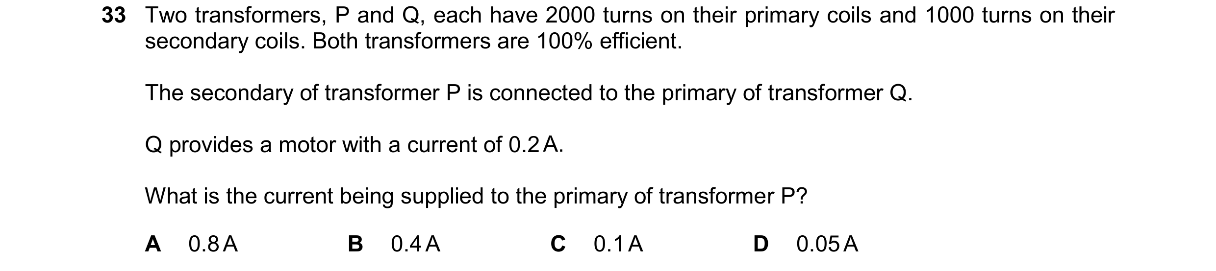
Q98 · Two transformers, P and Q, each have 2000 turns on their primary coils and 1000 turns on… 0972/21 Oct/Nov 2024
33 Two transformers, P and Q, each have 2000 turns on their primary coils and 1000 turns on their secondary coils. Both transformers are 100% efficient. The secondary of transformer P is connected to the primary of transformer Q. Q provides a motor with a current of 0.2 A. What is the current being supplied to the primary of transformer P? A 0.8 A B 0.4 A C 0.1 A D 0.05 A
1 marks
Answer: D
This question in 0972/21 Oct/Nov 2024
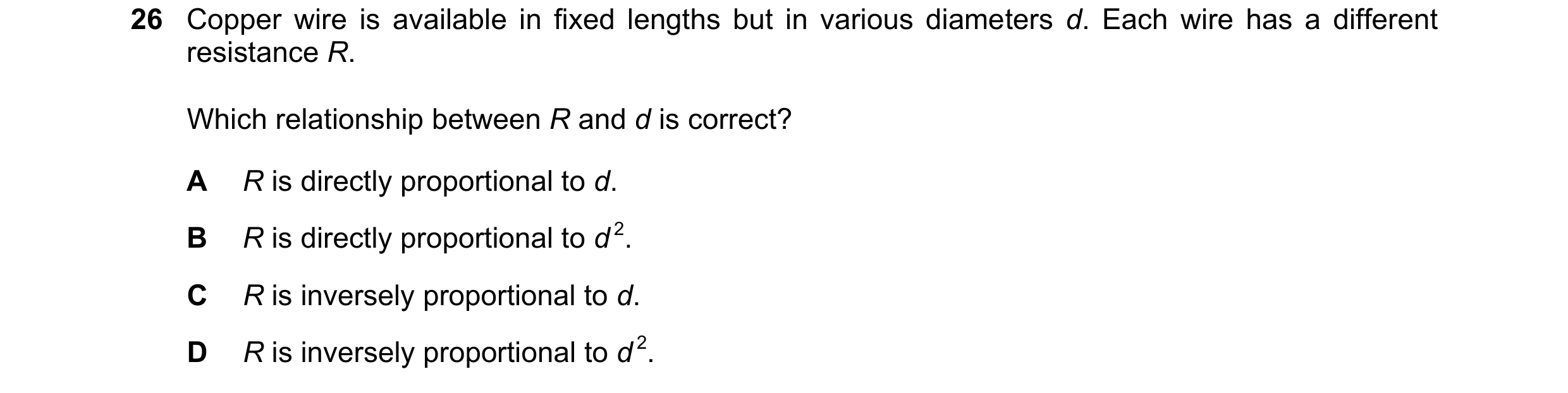
Q99 · Copper wire is available in fixed lengths but in various diameters d 0972/21 May/June 2025
26 Copper wire is available in fixed lengths but in various diameters d. Each wire has a different resistance R. Which relationship between R and d is correct? A R is directly proportional to d. B R is directly proportional to d 2. C R is inversely proportional to d. D R is inversely proportional to d 2.
1 marks
Answer: D
This question in 0972/21 May/June 2025
Q100 · The diagram shows three 20 resistors, R1, R2 and R3, and a switch S connected to a d.c 0972/21 May/June 2025
27 The diagram shows three 20 resistors, R1, R2 and R3, and a switch S connected to a d.c. power supply. R1 S R3 R2 Switch S is open. The potential difference (p.d.) across R3 is 9.0 V. What is the p.d. across R3 when switch S is closed? A 3.0 V B 6.0 V C 12 V D 27 V
1 marks
Answer: C
This question in 0972/21 May/June 2025
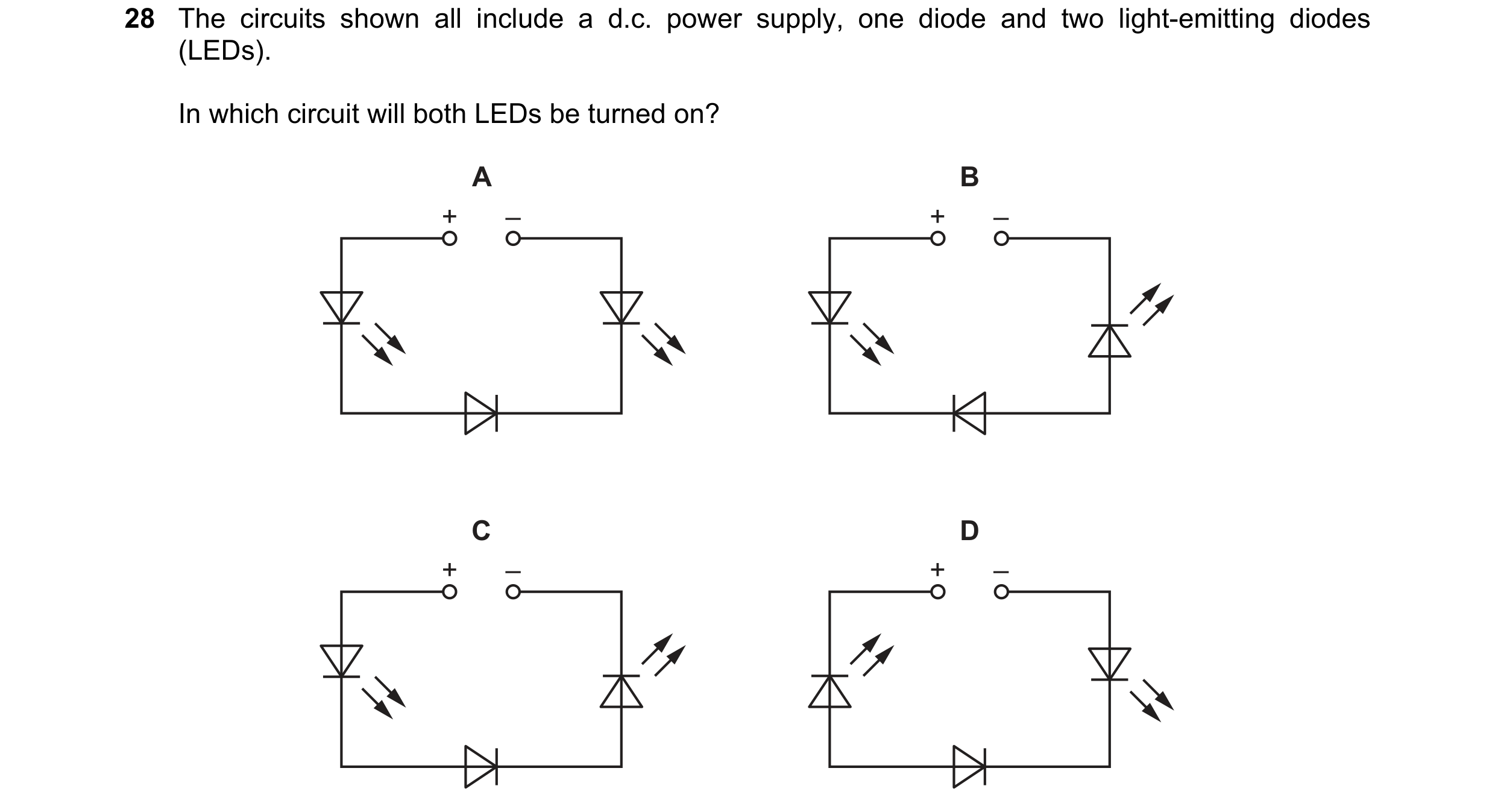
Q101 · The circuits shown all include a d.c 0972/21 May/June 2025
28 The circuits shown all include a d.c. power supply, one diode and two light-emitting diodes (LEDs). In which circuit will both LEDs be turned on? A B + – + – C D + – + –
1 marks
Answer: C
This question in 0972/21 May/June 2025
Q102 · A cell passes a current of 2.0 A in a circuit for 30 s 0972/21 Oct/Nov 2025
27 A cell passes a current of 2.0 A in a circuit for 30 s. In this time, the cell transfers 120 J of energy. What is the electromotive force (e.m.f.) of the cell? A 0.50 V B 1.5 V C 2.0 V D 8.0 V
1 marks
Answer: C
This question in 0972/21 Oct/Nov 2025
Q103 · The diagram shows two resistors in series connected to a power supply 0972/21 Oct/Nov 2025
28 The diagram shows two resistors in series connected to a power supply.
12.0V
S) t+ =
—
6.09 R
The reading on the voltmeter is 3.0V when the switch is closed.
What is the resistance of resistor R?
A 0.679 Bo 1.2Q C 1.509 D 2.0Q
1 marks
Answer: D
This question in 0972/21 Oct/Nov 2025
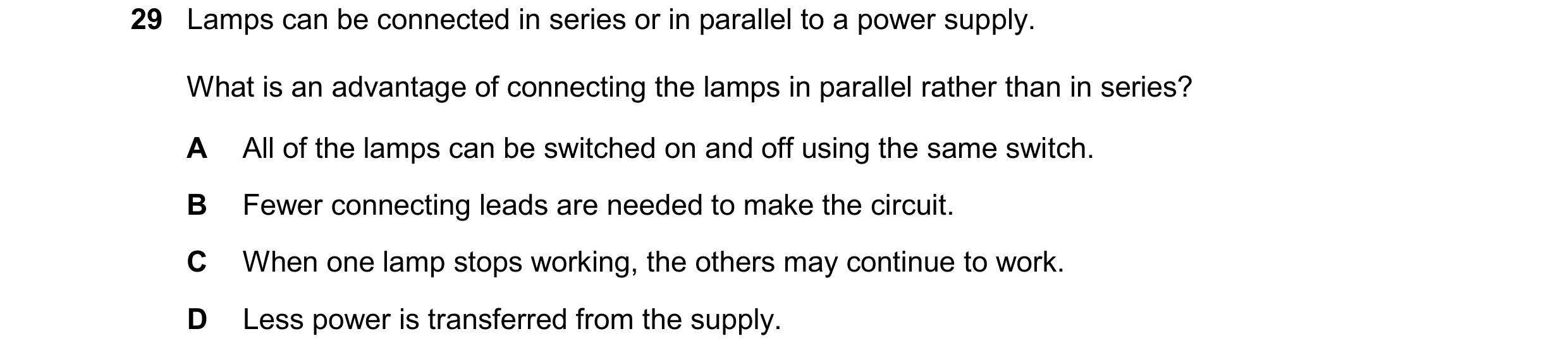
Q104 · Lamps can be connected in series or in parallel to a power supply 0972/21 Oct/Nov 2025
29 Lamps can be connected in series or in parallel to a power supply. What is an advantage of connecting the lamps in parallel rather than in series? A All of the lamps can be switched on and off using the same switch. B Fewer connecting leads are needed to make the circuit. C When one lamp stops working, the others may continue to work. D Less power is transferred from the supply.
1 marks
Answer: C
This question in 0972/21 Oct/Nov 2025
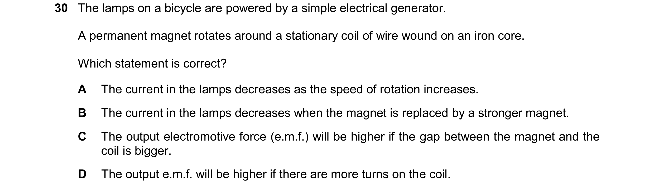
Q105 · The lamps on a bicycle are powered by a simple electrical generator 0972/21 Oct/Nov 2025
30 The lamps on a bicycle are powered by a simple electrical generator. A permanent magnet rotates around a stationary coil of wire wound on an iron core. Which statement is correct? A The current in the lamps decreases as the speed of rotation increases. B The current in the lamps decreases when the magnet is replaced by a stronger magnet. C The output electromotive force (e.m.f.) will be higher if the gap between the magnet and the coil is bigger. D The output e.m.f. will be higher if there are more turns on the coil.
1 marks
Answer: D
This question in 0972/21 Oct/Nov 2025
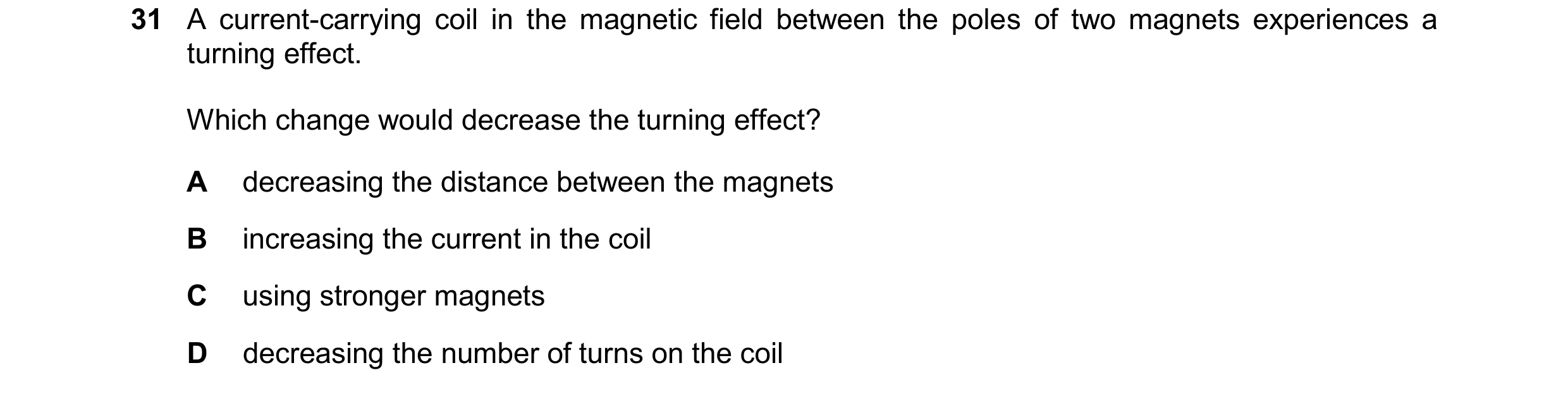
Q106 · A current-carrying coil in the magnetic field between the poles of two magnets… 0972/21 Oct/Nov 2025
31 A current-carrying coil in the magnetic field between the poles of two magnets experiences a turning effect. Which change would decrease the turning effect? A decreasing the distance between the magnets B increasing the current in the coil C using stronger magnets D decreasing the number of turns on the coil
1 marks
Answer: D
This question in 0972/21 Oct/Nov 2025
Q107 · Cables transmit electrical power from the output of the transformer at a power station to… 0972/21 Oct/Nov 2025
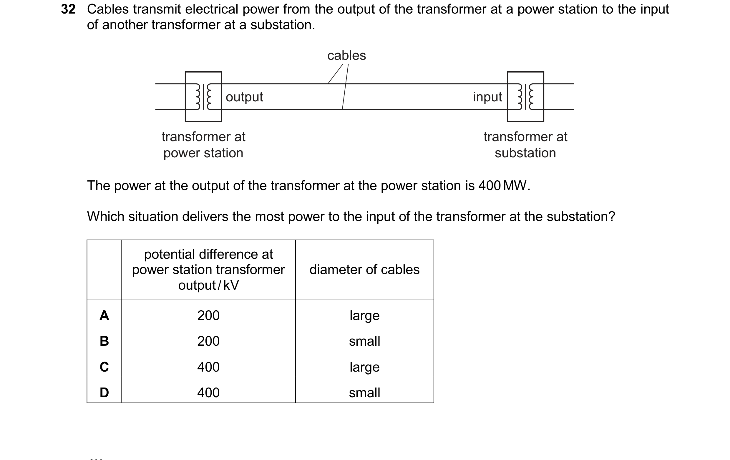
32 Cables transmit electrical power from the output of the transformer at a power station to the input of another transformer at a substation. cables output input transformer at transformer at power station substation The power at the output of the transformer at the power station is 400 MW. Which situation delivers the most power to the input of the transformer at the substation? potential difference at power station transformer diameter of cables output / kV A 200 large B 200 small C 400 large D 400 small
1 marks
Answer: C
This question in 0972/21 Oct/Nov 2025


 1 / 39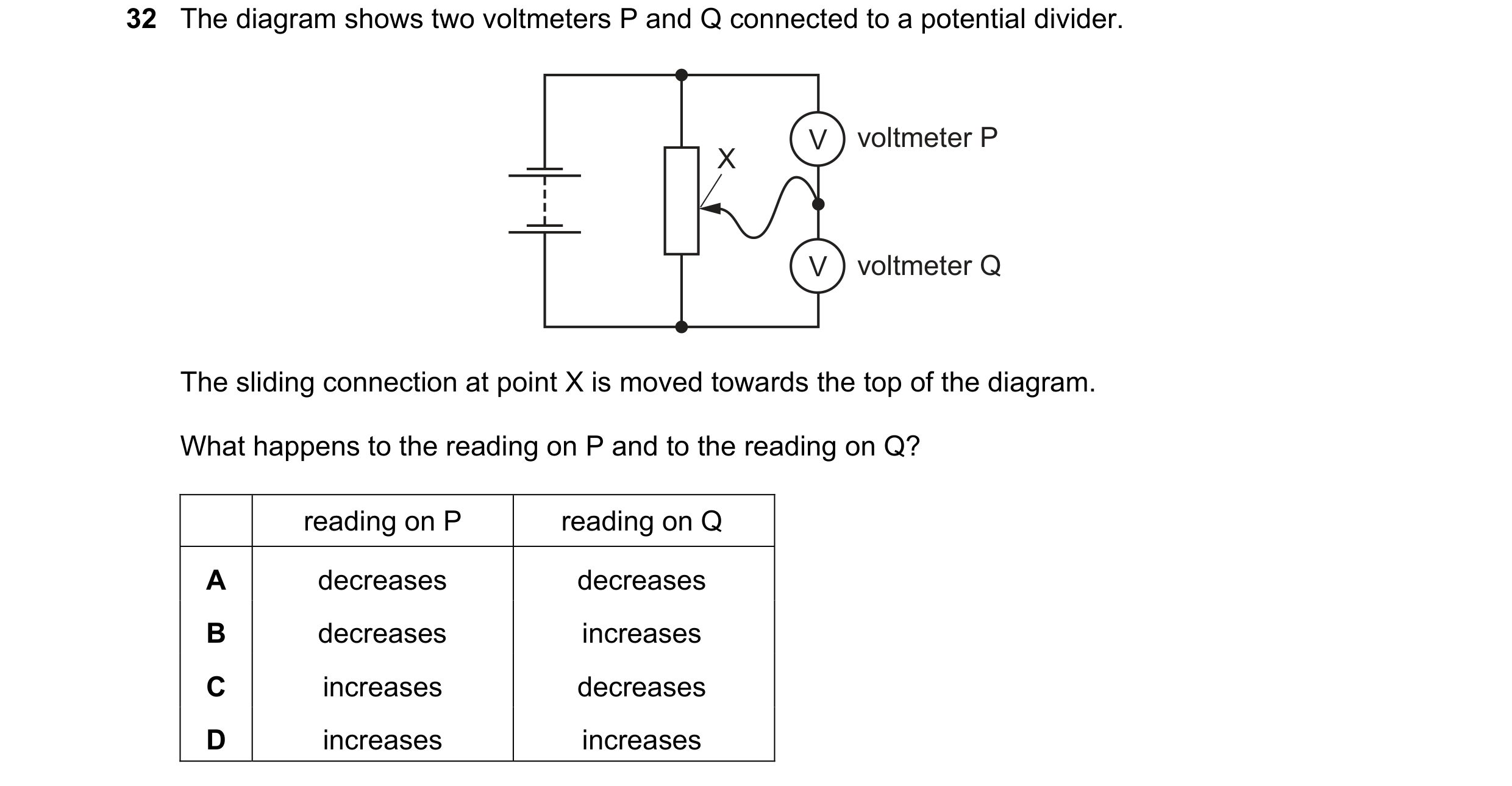
 2 / 39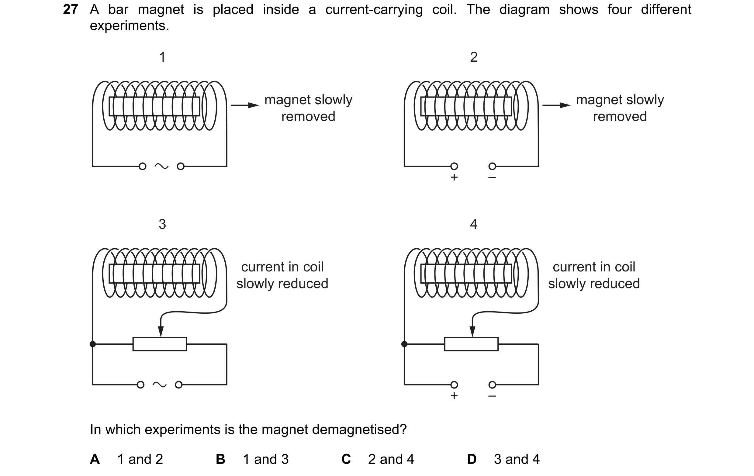
 3 / 39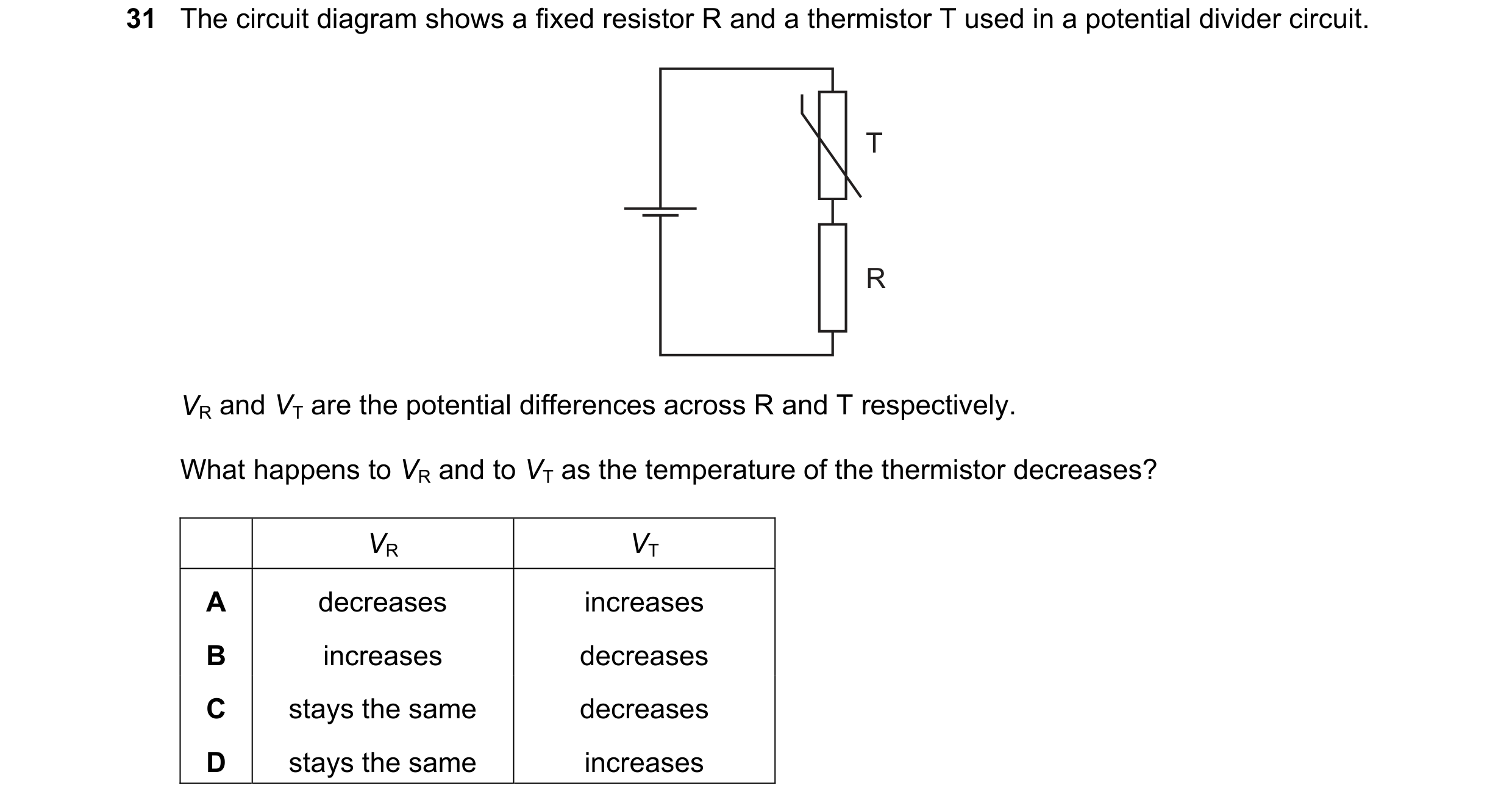
 4 / 39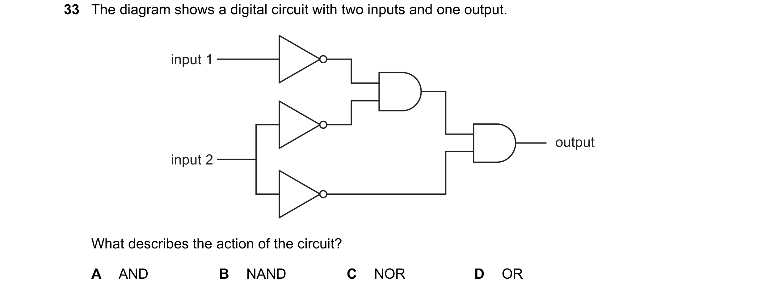
 5 / 39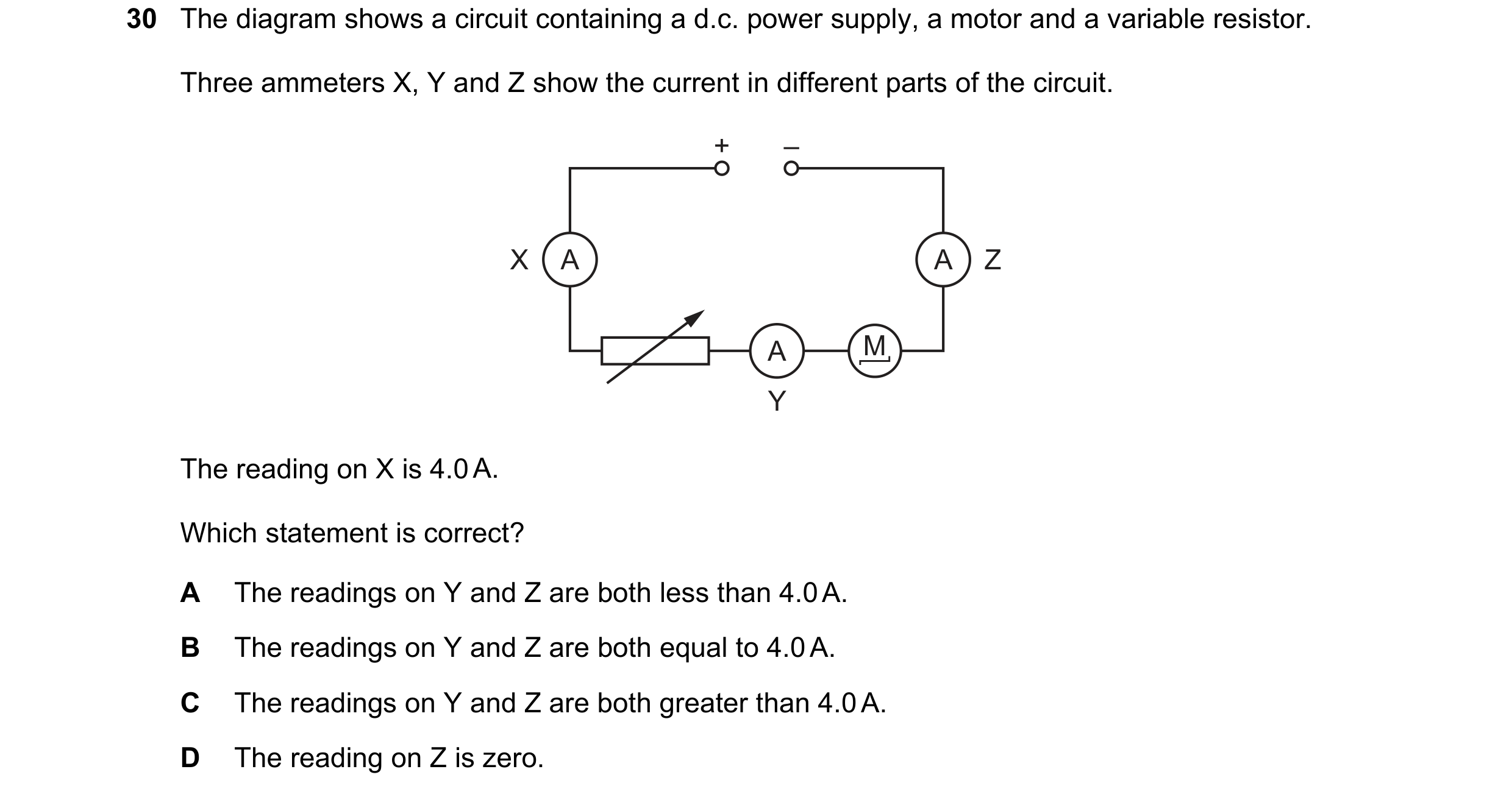
 6 / 39
 7 / 39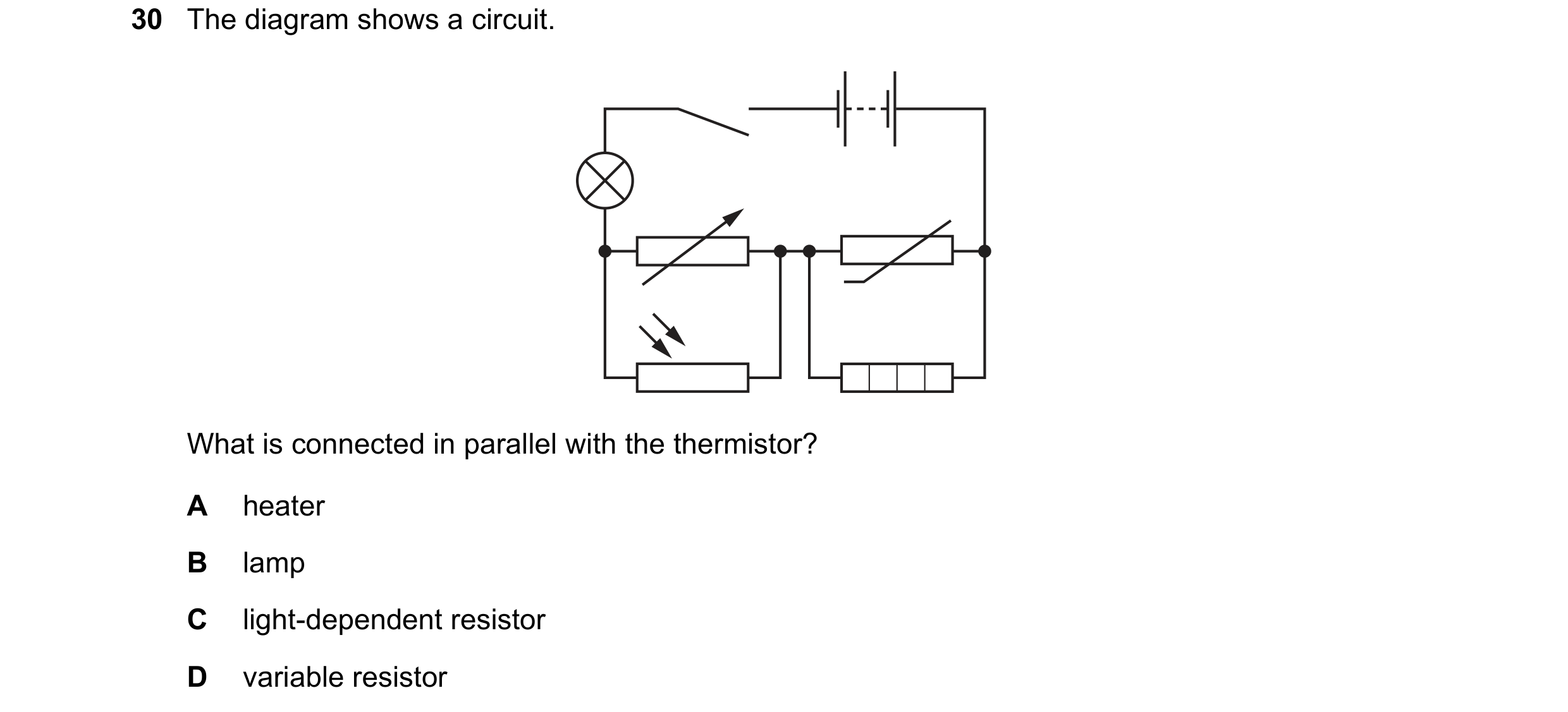
 8 / 39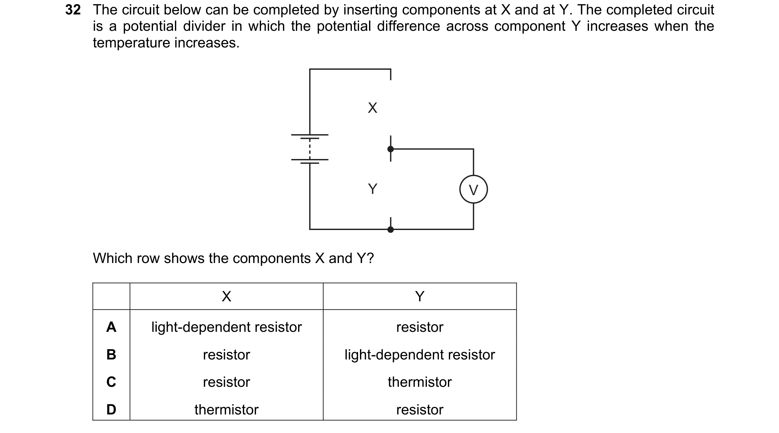

 9 / 39
 10 / 39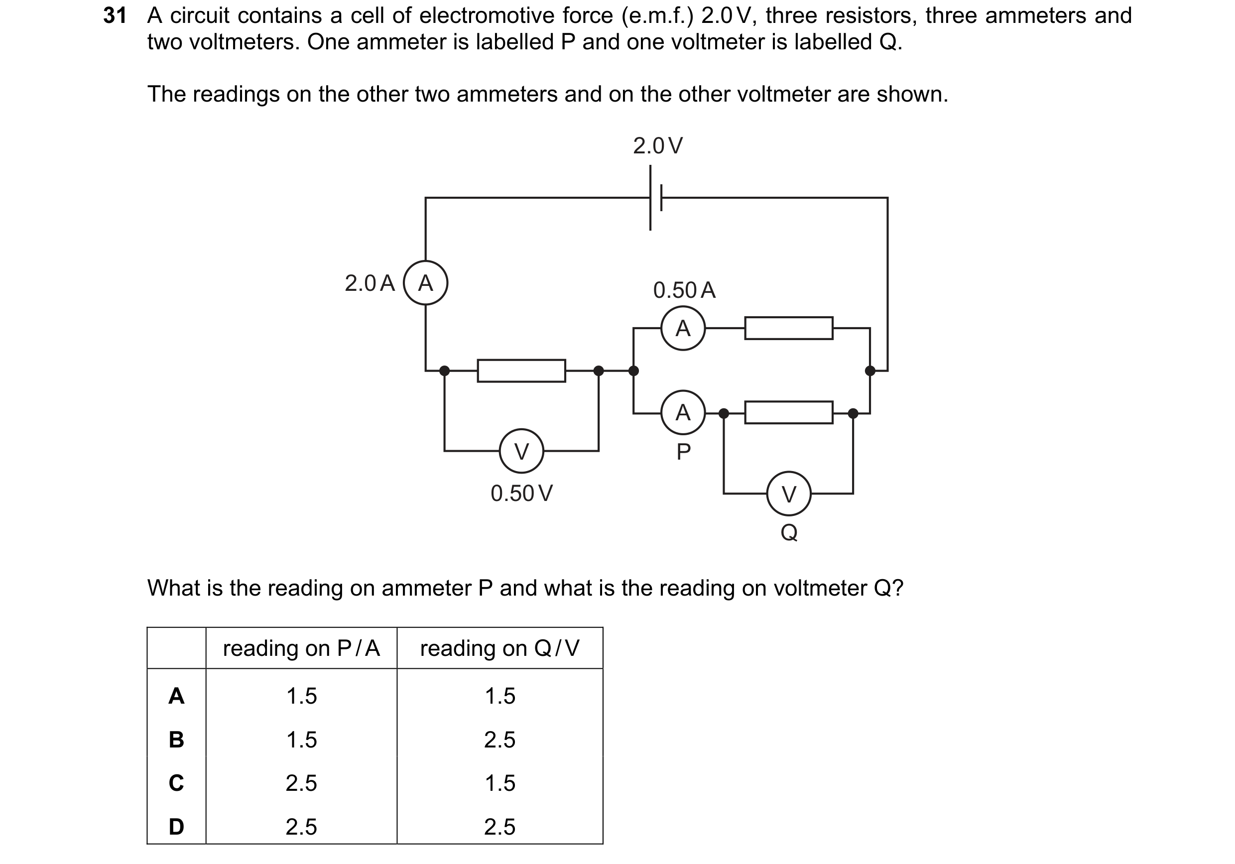
 11 / 39
 12 / 39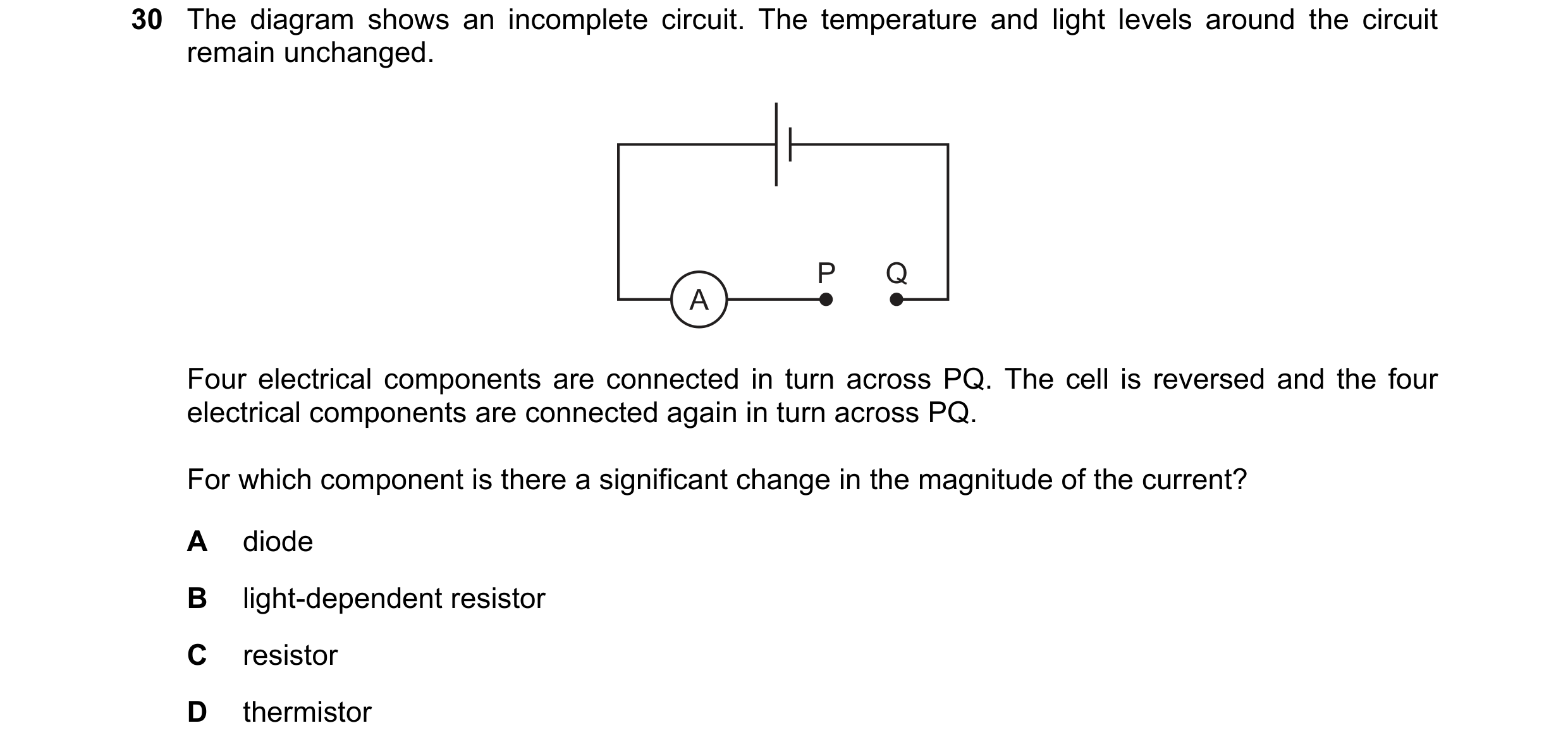
 13 / 39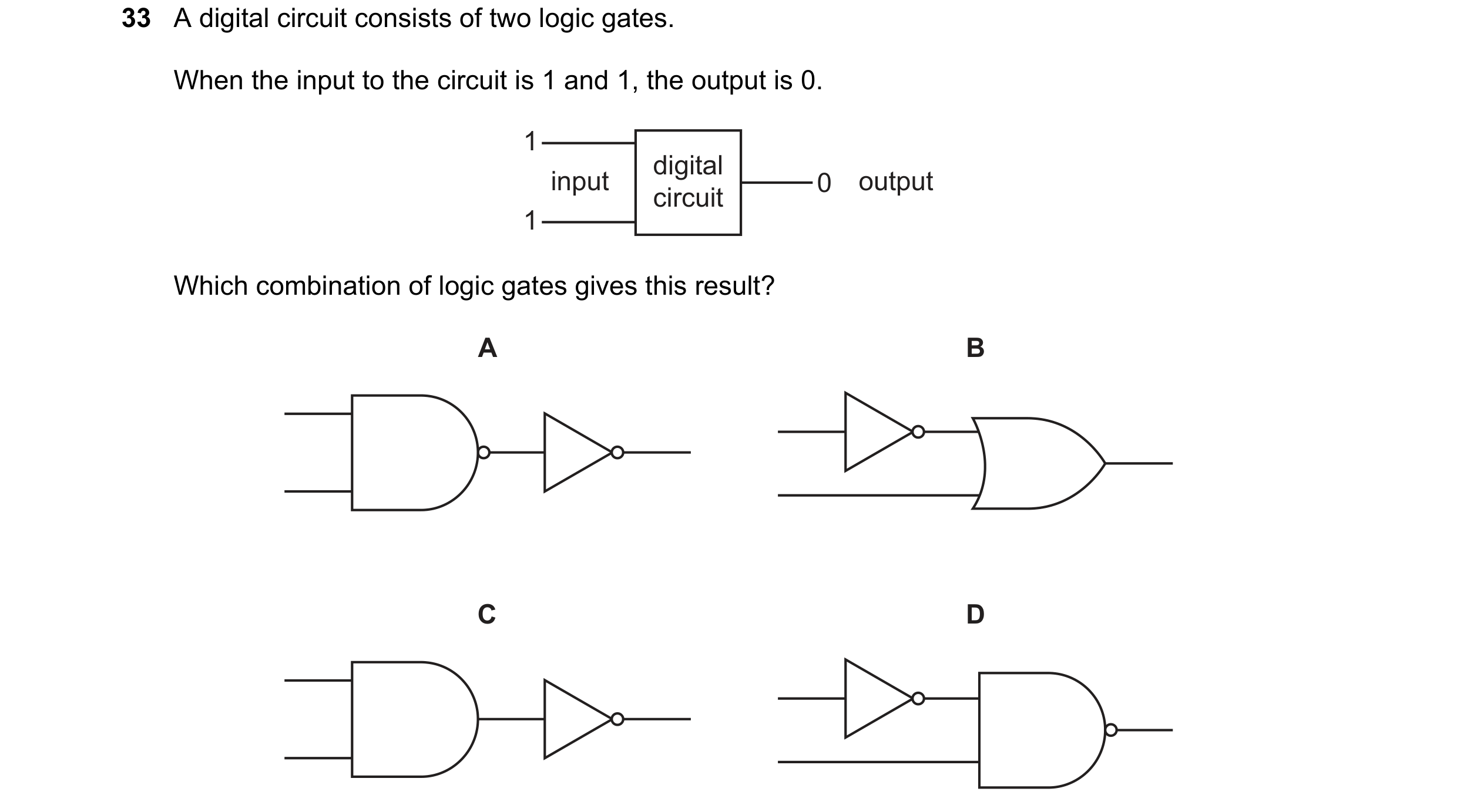
 14 / 39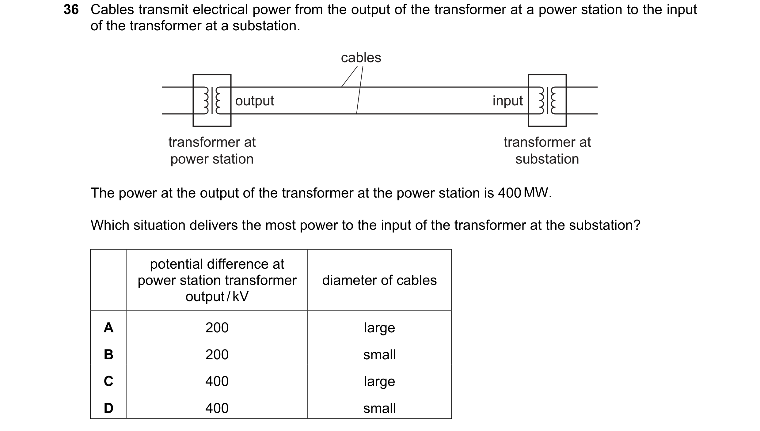
 15 / 39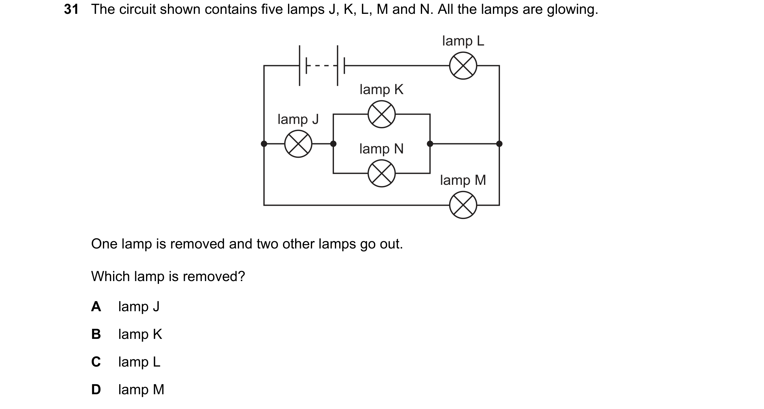
 16 / 39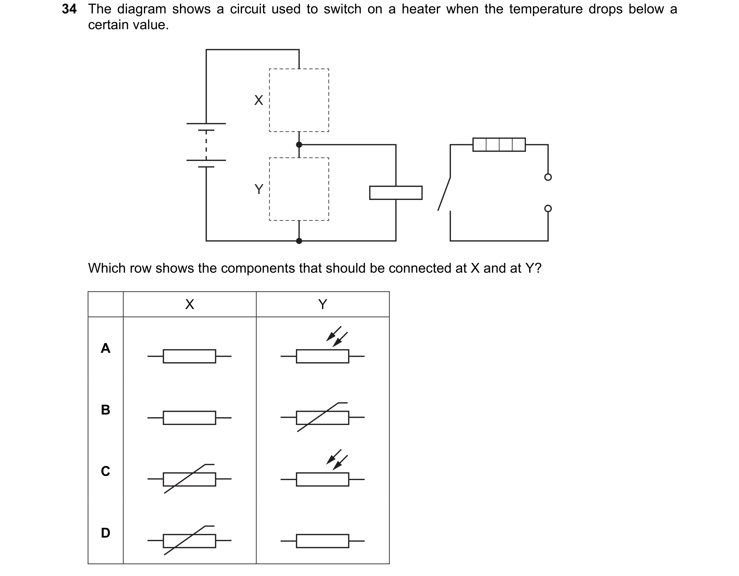
 17 / 39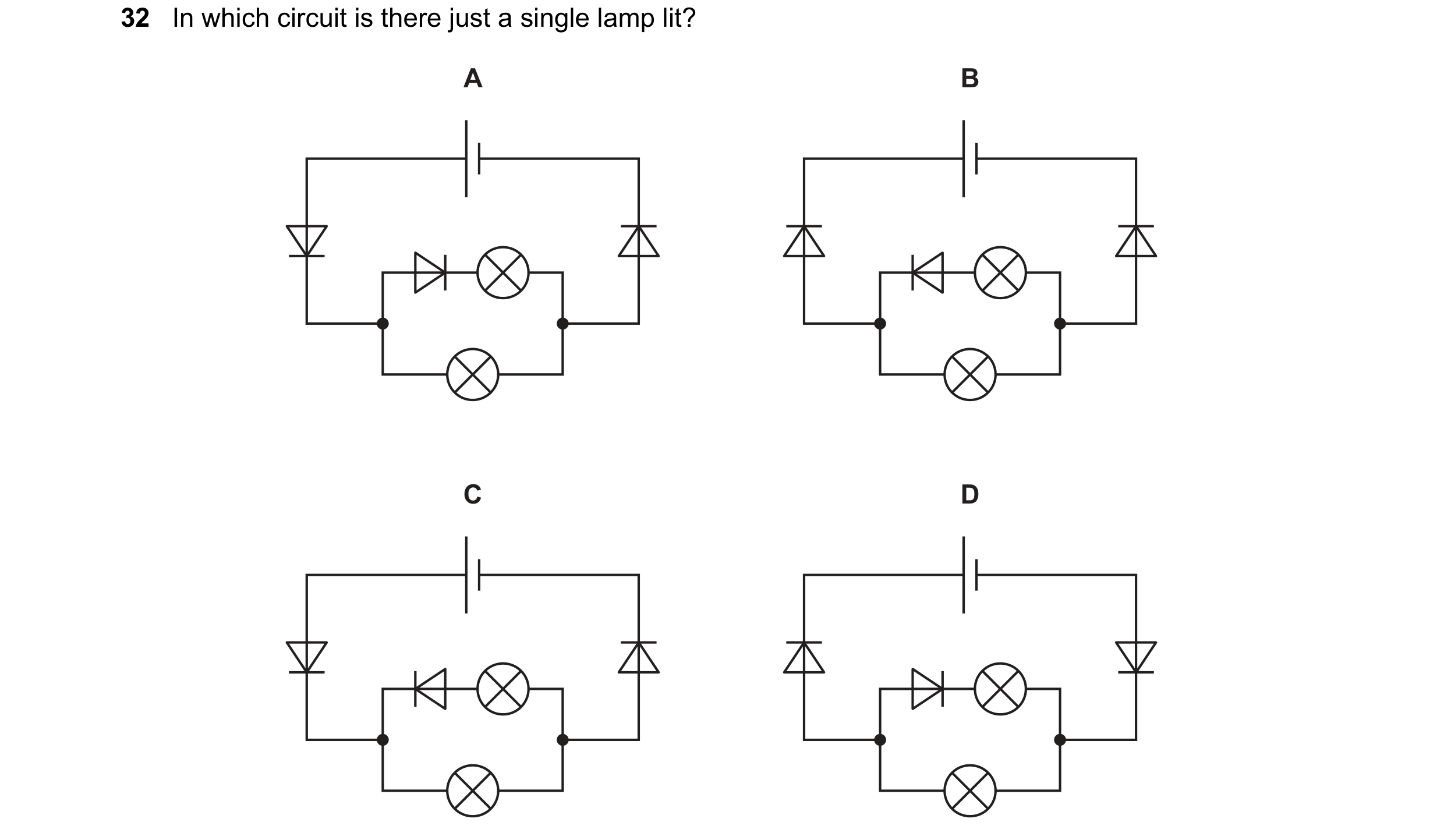
 18 / 39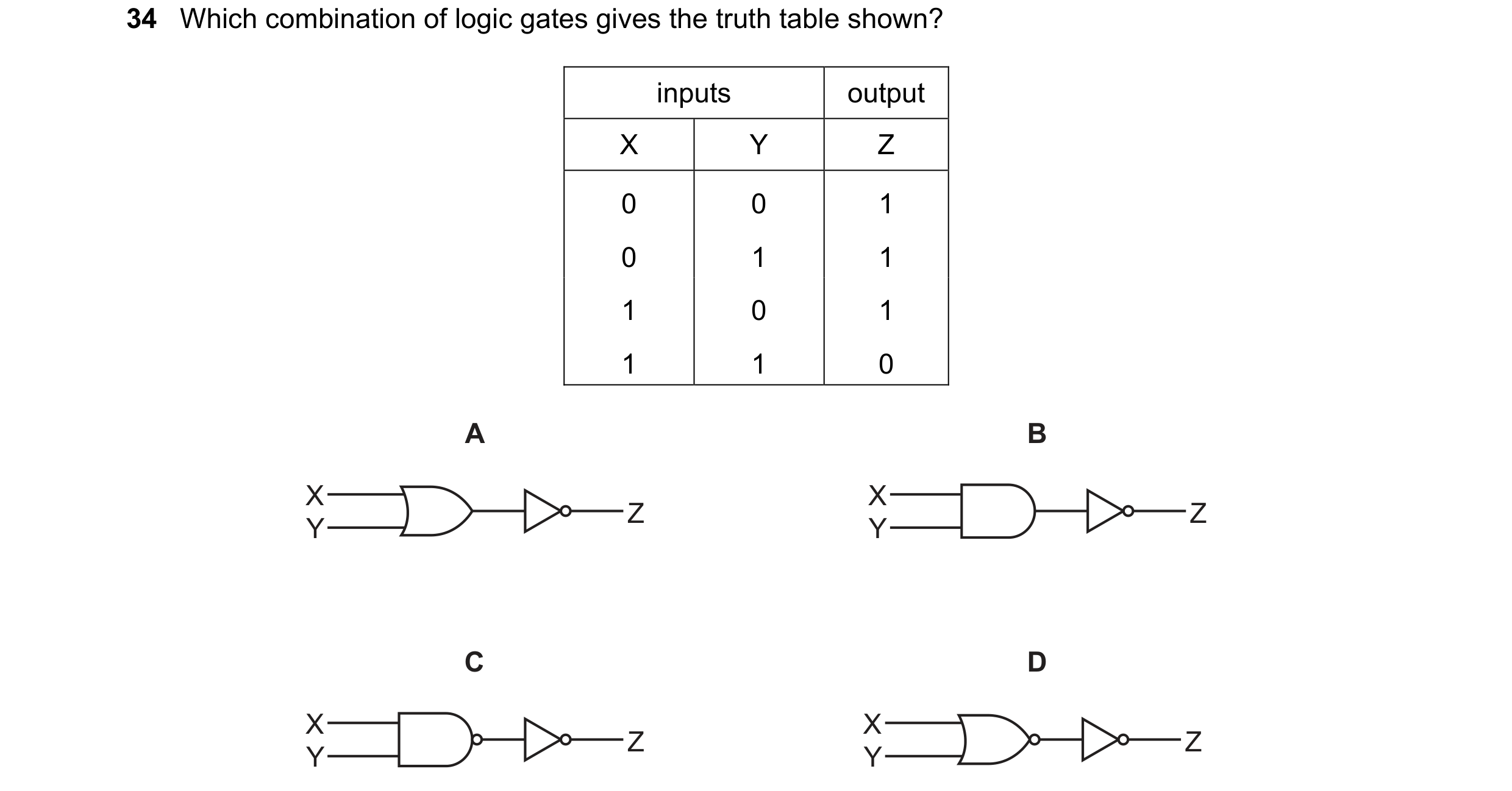
 19 / 39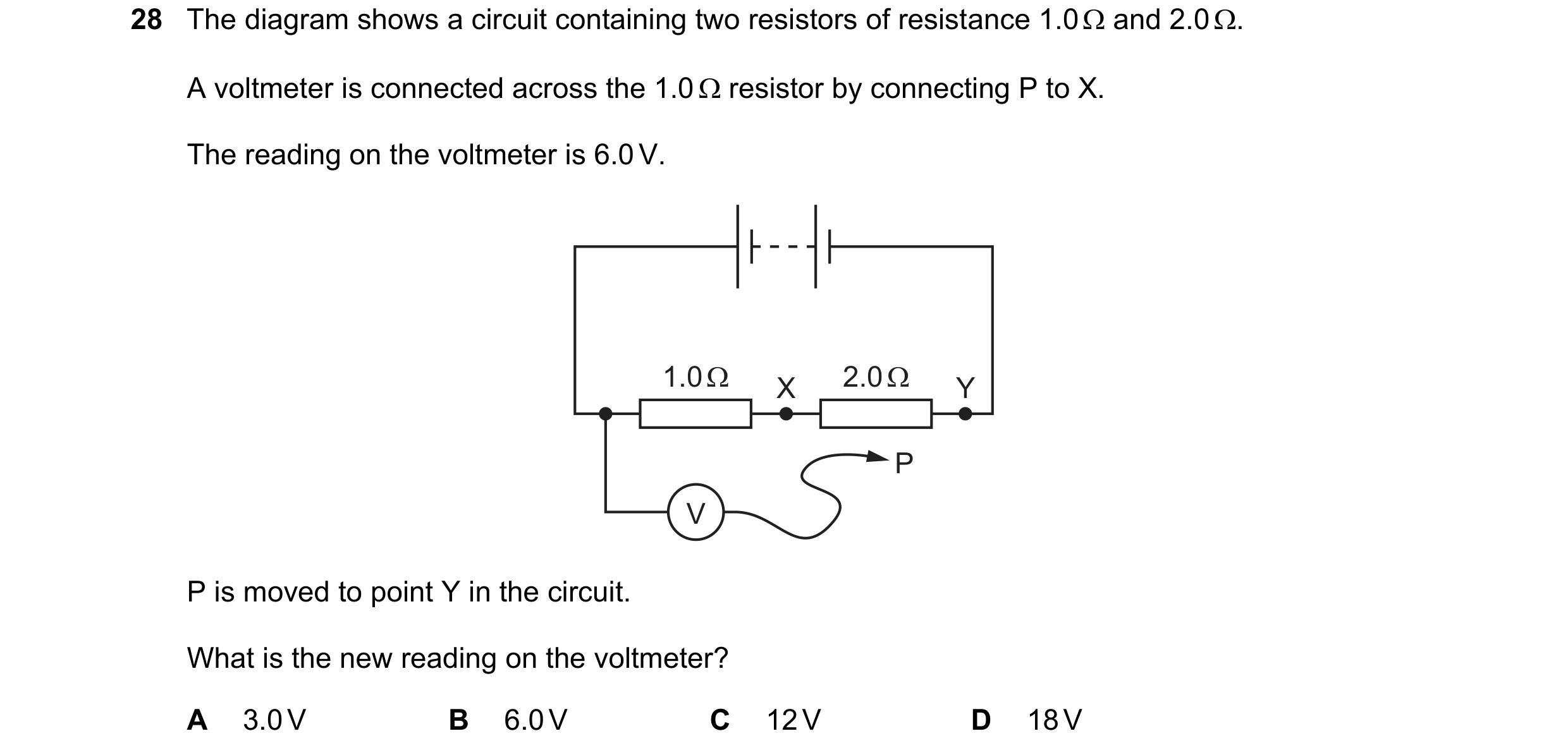
 20 / 39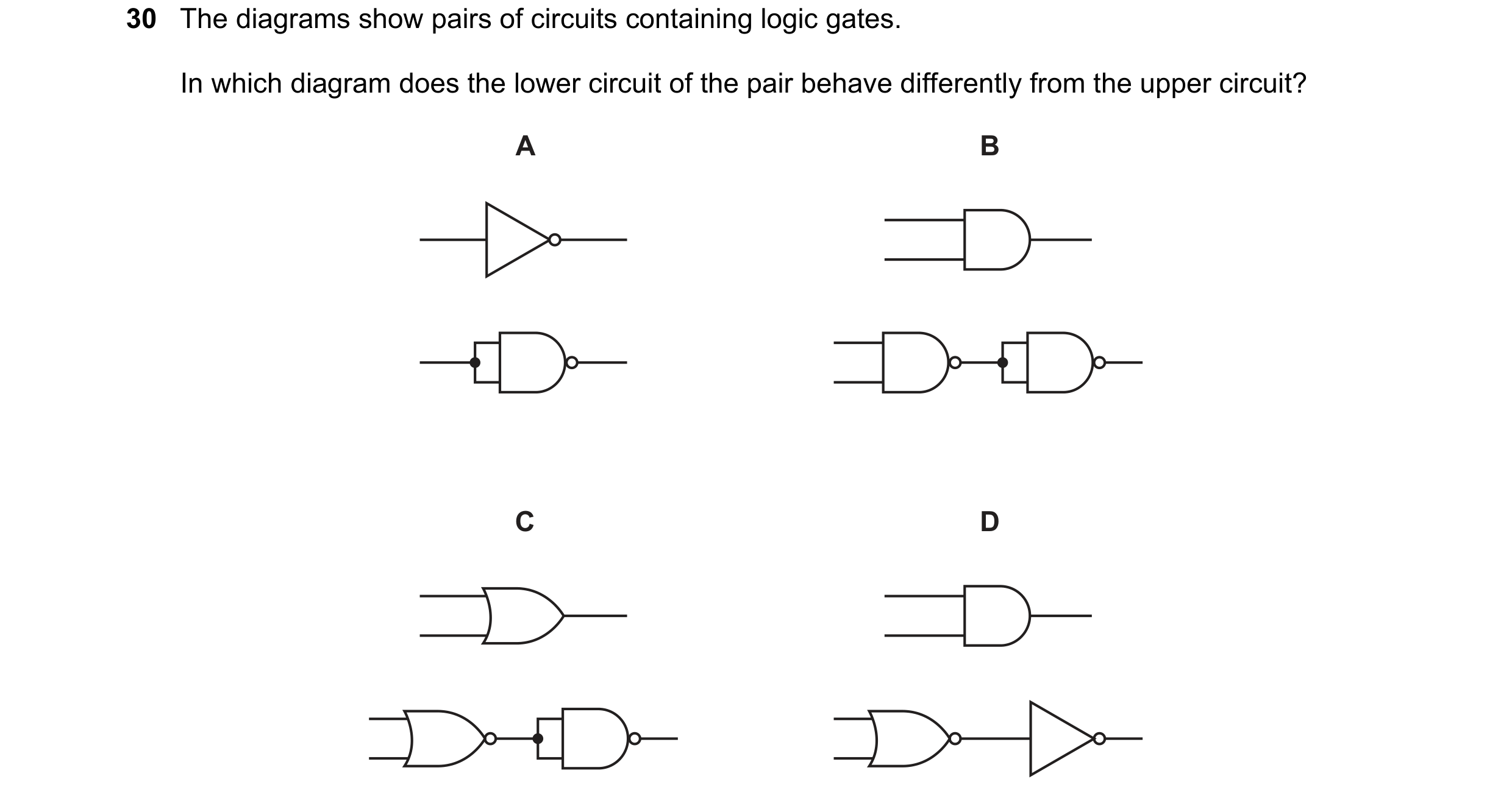
 21 / 39
 22 / 39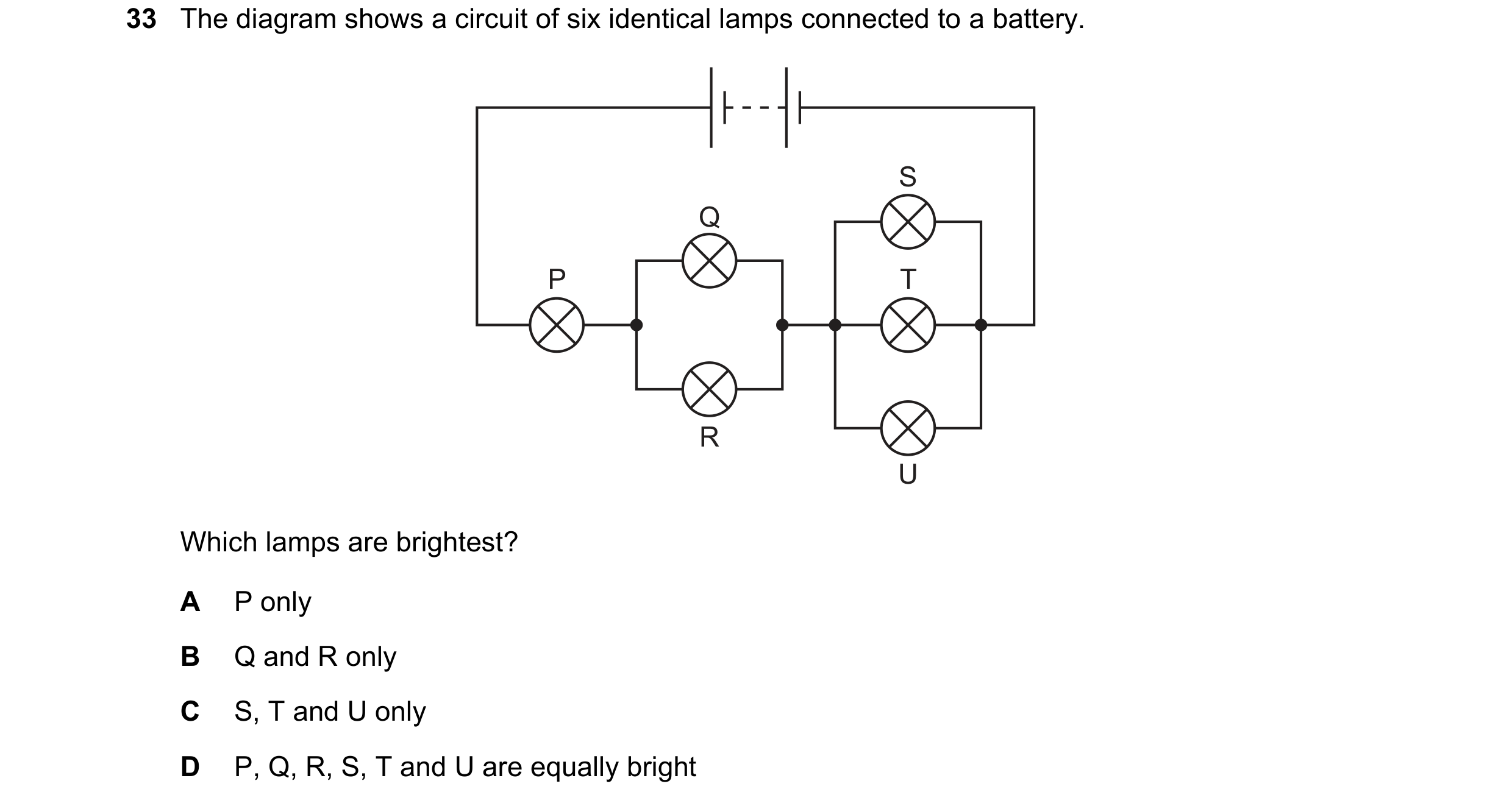

 23 / 39
 24 / 39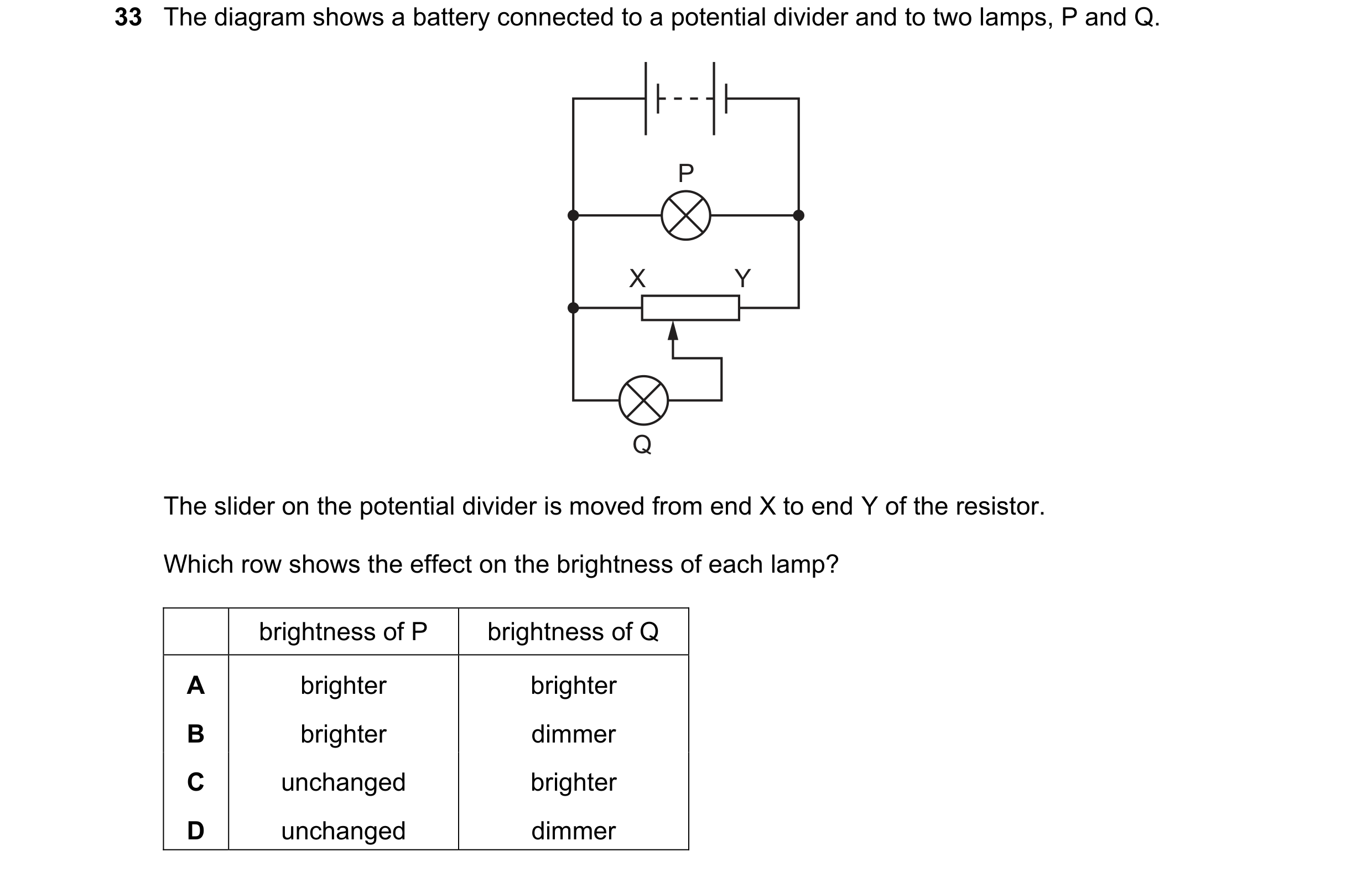
 25 / 39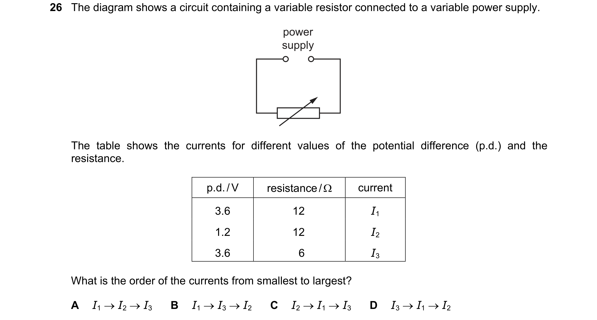

 26 / 39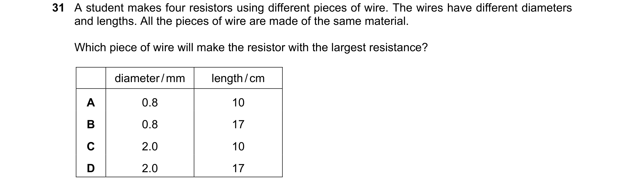
 27 / 39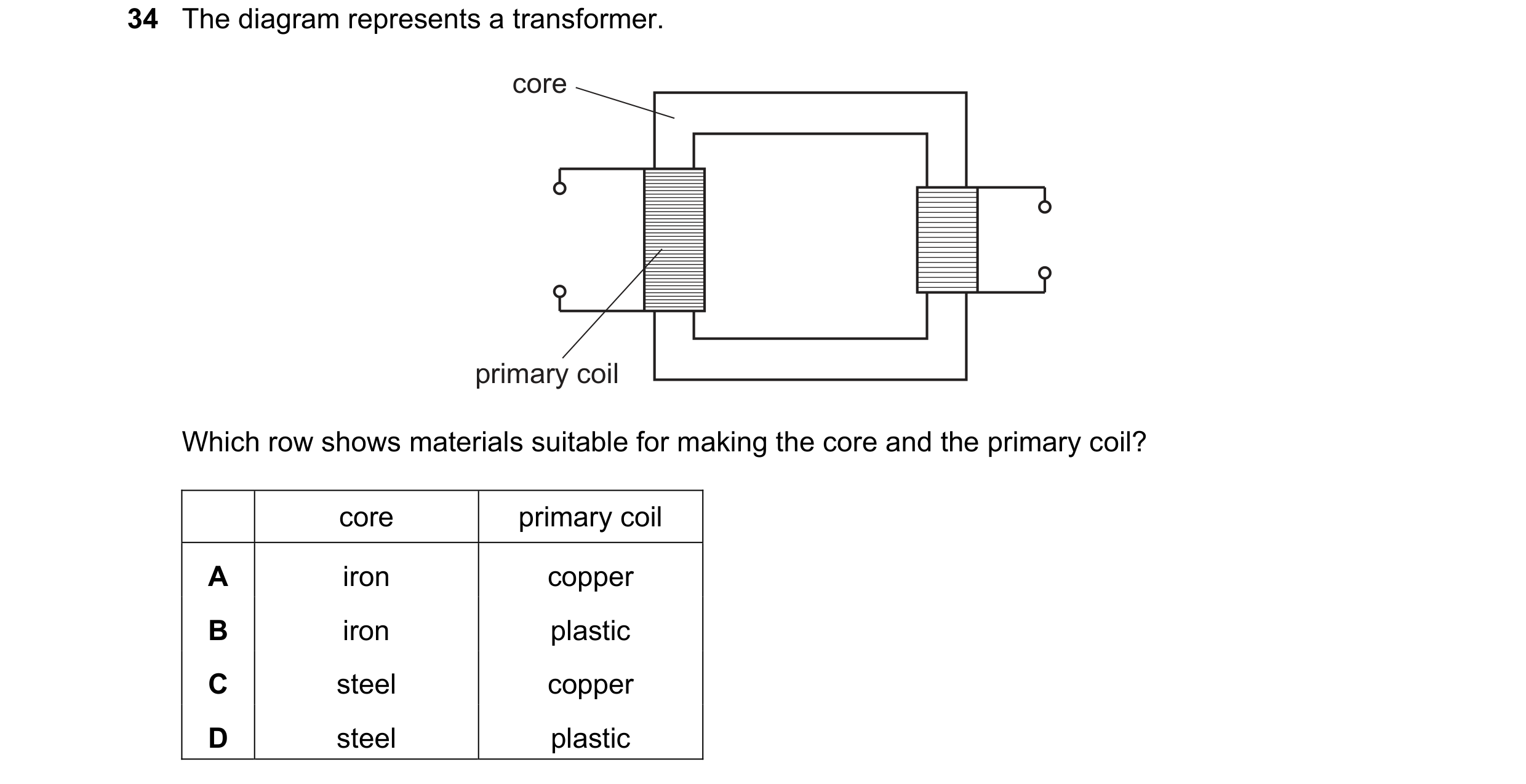
 28 / 39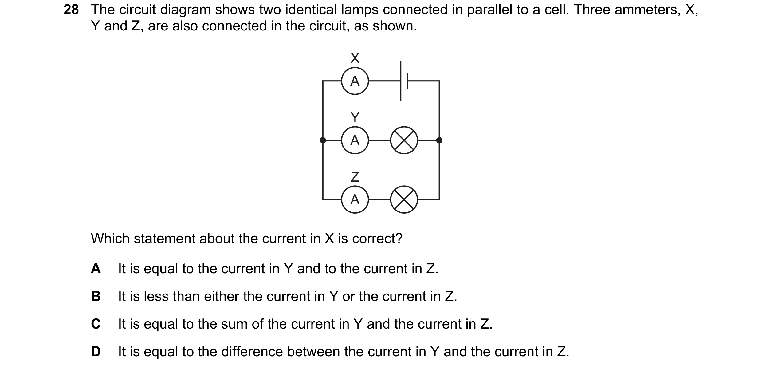
 29 / 39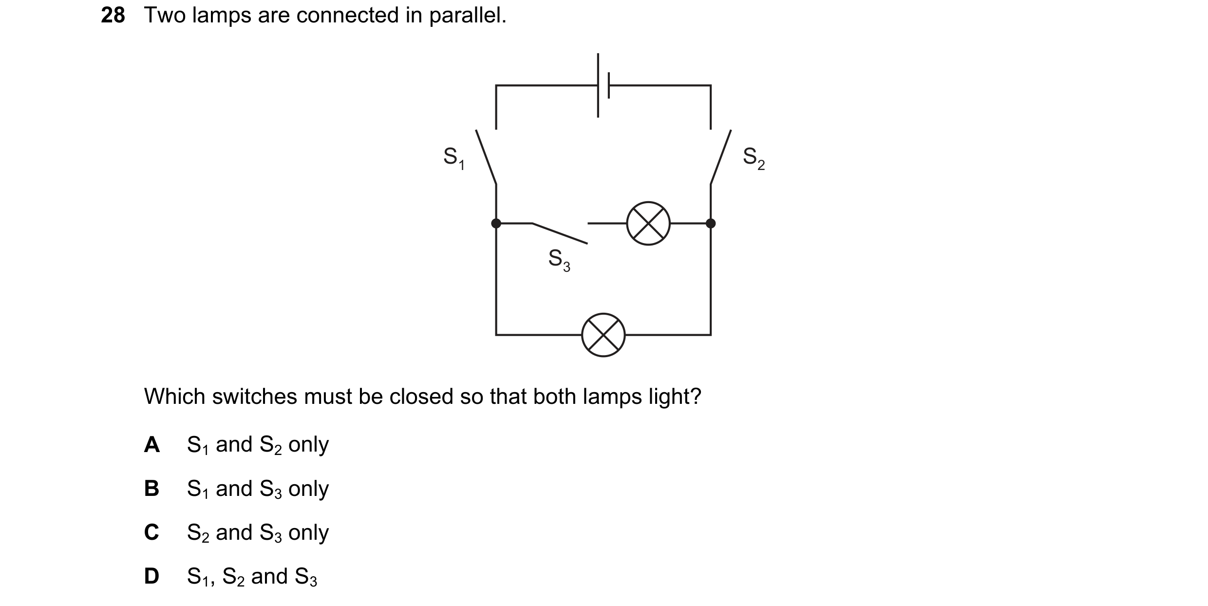

 30 / 39
 31 / 39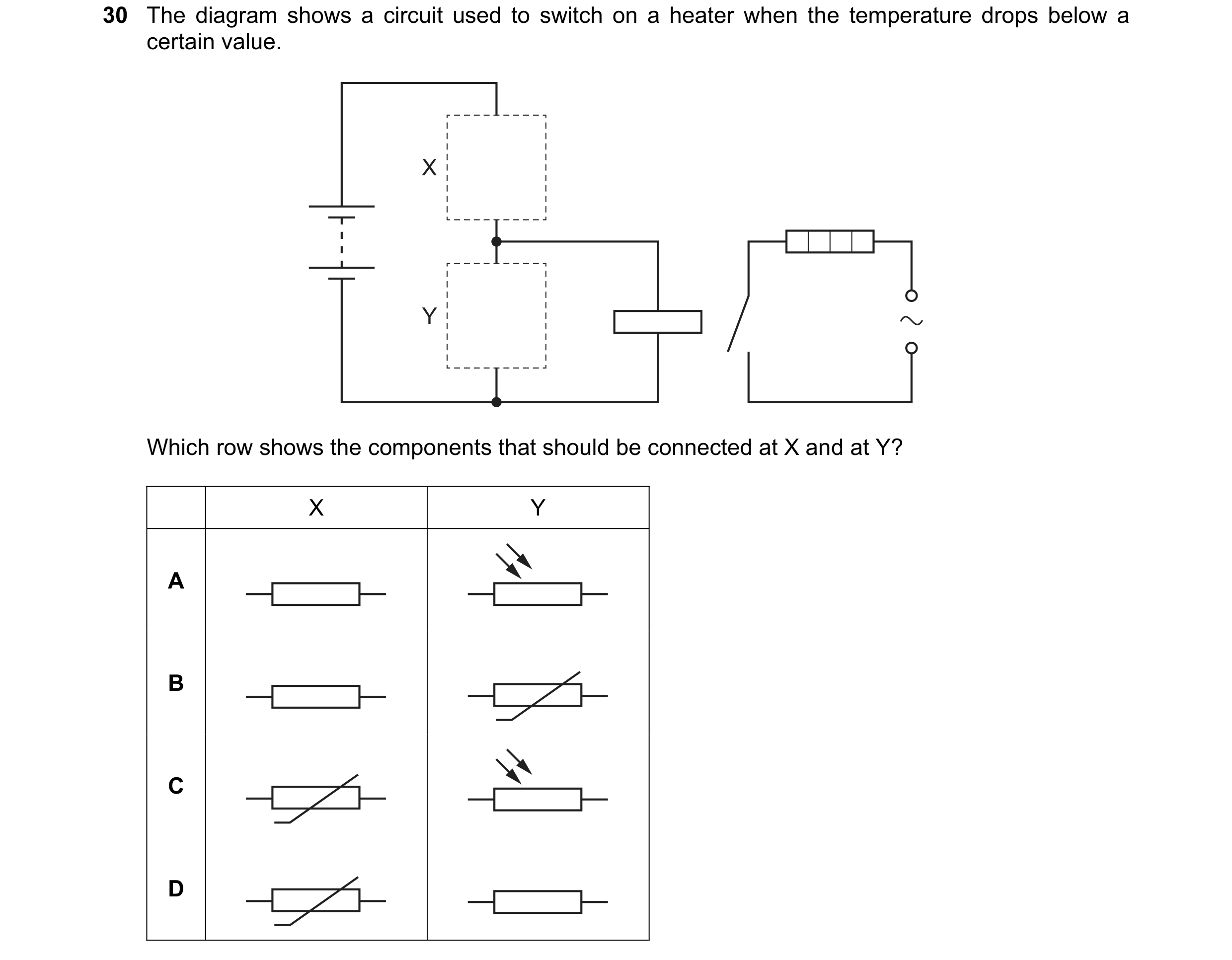
 32 / 39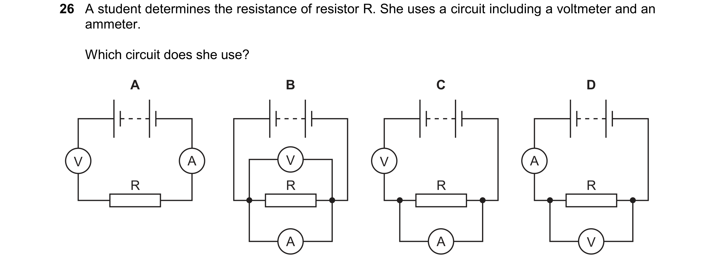
 33 / 39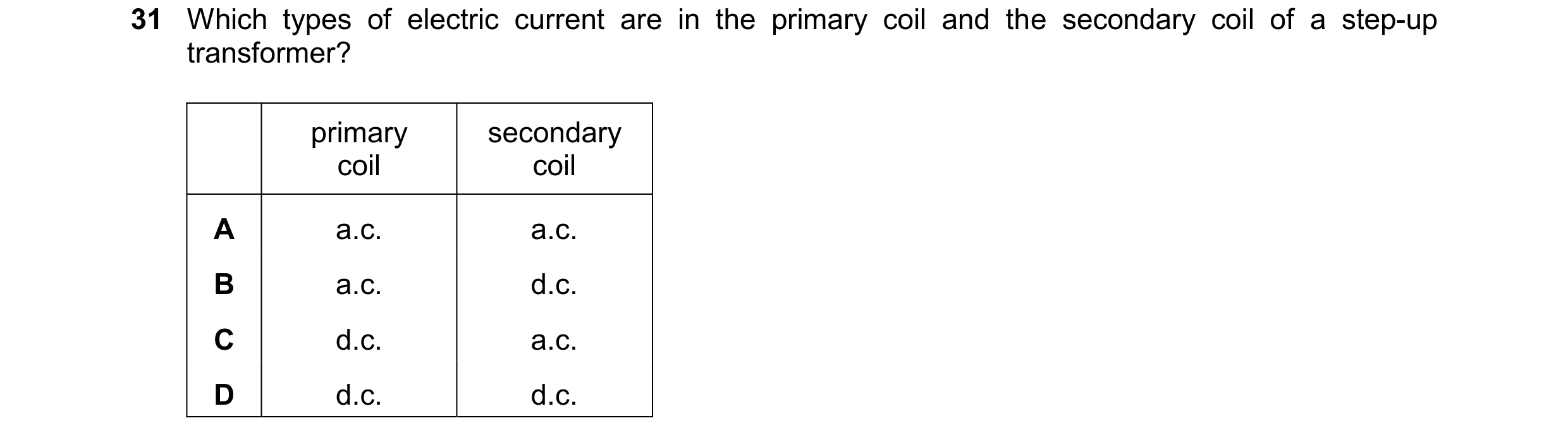
 34 / 39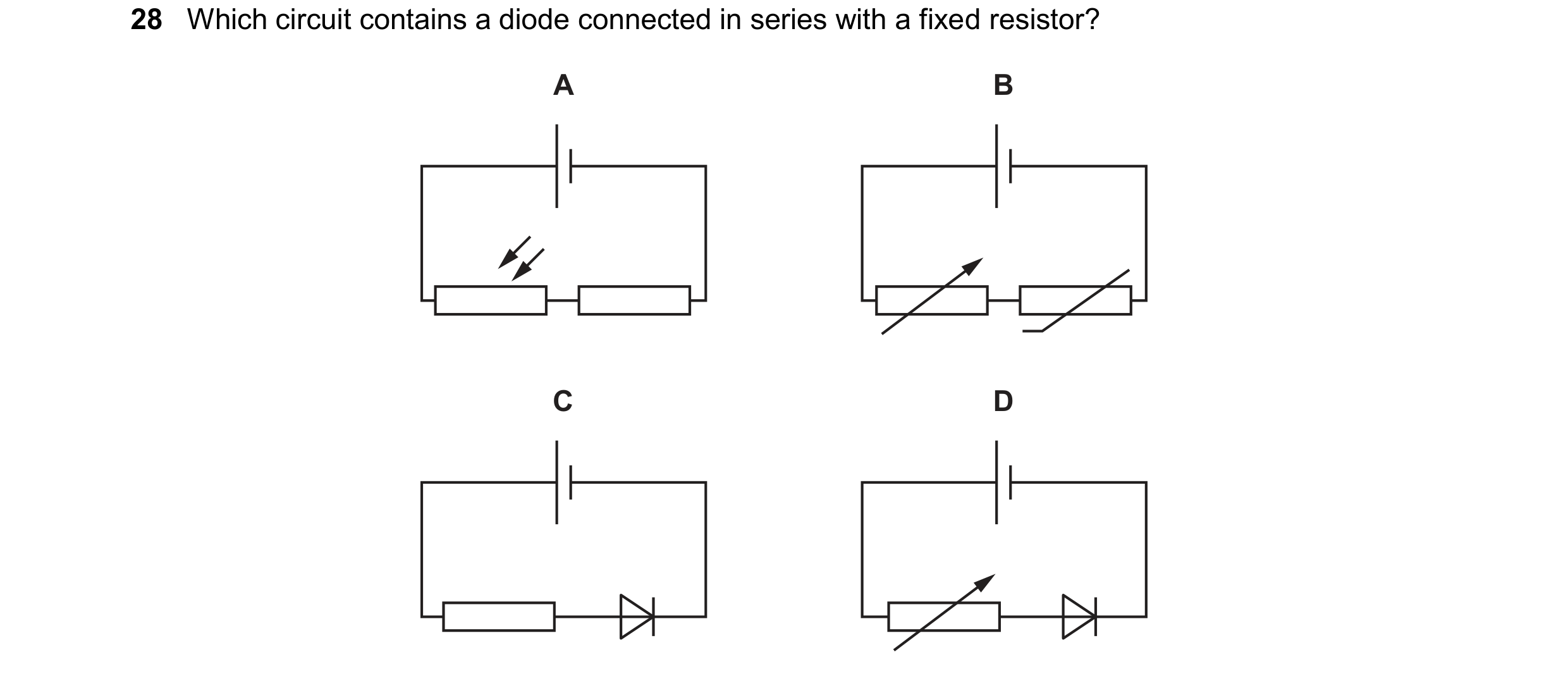
 35 / 39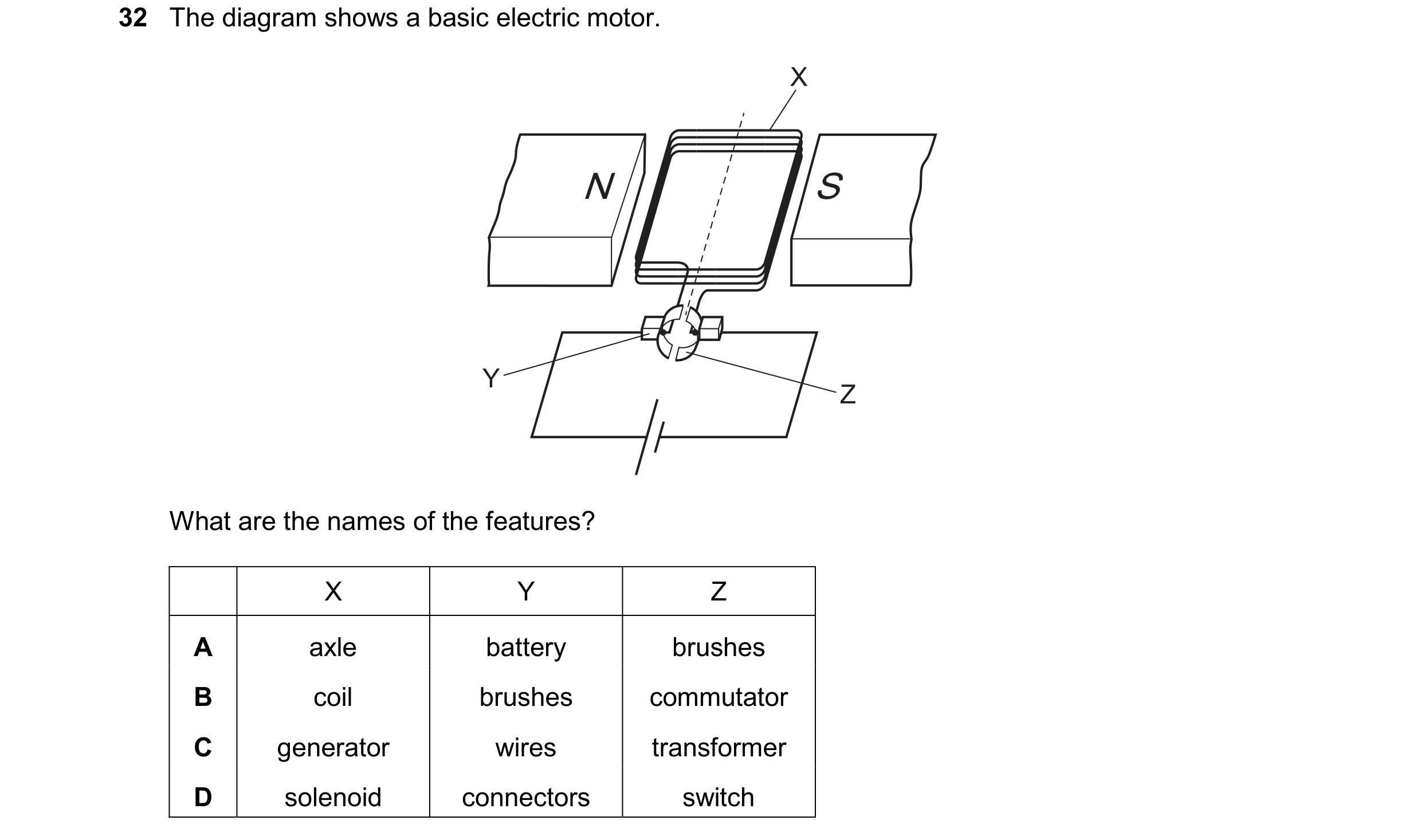
 36 / 39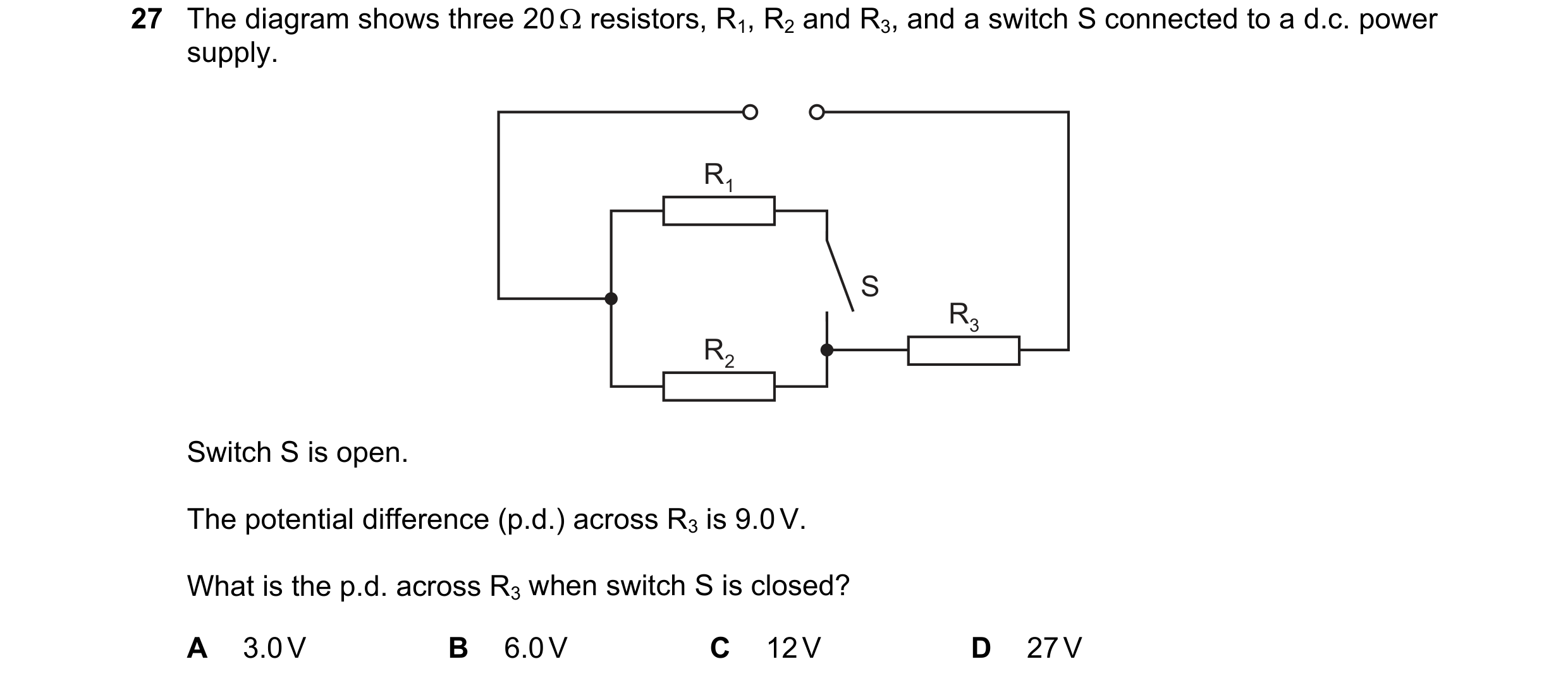
 37 / 39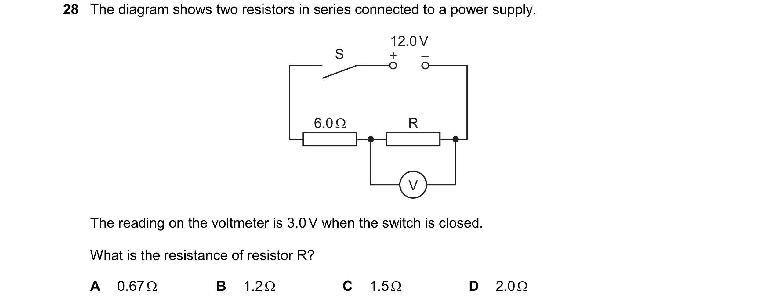
 38 / 39
 39 / 39