Cambridge IGCSE Design and Technology 0445 — 2025 May/June Paper 4 · Variant 3
0445/43/M/J/25 · 12 questions · 50 marks · 60 min
The question paper and its mark scheme, free to read here and free to download. This is Cambridge’s own paper, exactly as it was sat.
Question paper20 pages





Mark scheme15 pages
Answers below. Sit the paper first if you are practising.
Questions as text
Q1 · Name two fossil fuels
1 (a) Name two fossil fuels. 1 ................................................................................................................................................ 2 ................................................................................................................................................ [2] (b) Explain how solar energy can be used to provide power at night. ................................................................................................................................................... ................................................................................................................................................... ............................................................................................................................................. [2]
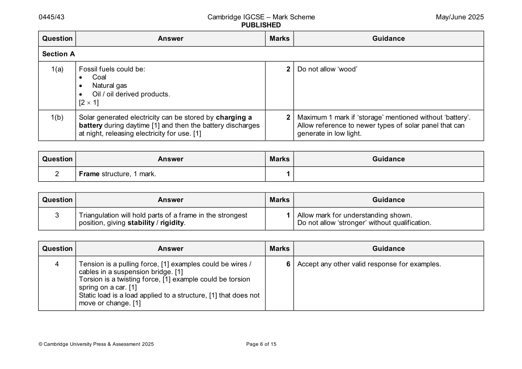
Mark scheme: Question Answer Marks Guidance Section A 1(a) Fossil fuels could be: 2 Do not allow ‘wood’ • Coal • Natural gas • Oil / oil derived products. [2 1] 1(b) Solar generated electricity can be stored by charging a 2 Maximum 1 mark if ‘storage’ mentioned without ‘battery’. battery during daytime [1] and then the battery discharges Allow reference to newer types of solar panel that can at night, releasing electricity for use. [1] generate in low light.
Q2 · Name the type of structure shown in Fig
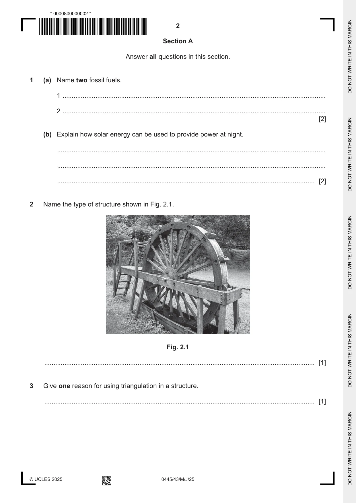
2 Name the type of structure shown in Fig. 2.1. Fig. 2.1 .................................................................................................................................................... [1]
Mark scheme: 2 Frame structure, 1 mark. 1
Q3 · Give one reason for using triangulation in a structure
3 Give one reason for using triangulation in a structure. .................................................................................................................................................... [1]
Mark scheme: 3 Triangulation will hold parts of a frame in the strongest 1 Allow mark for understanding shown. position, giving stability / rigidity. Do not allow ‘stronger’ without qualification.
Q4 · Describe, using examples, the following forces that can act on a structure
4 Describe, using examples, the following forces that can act on a structure. tension .............................................................................................................................................. .......................................................................................................................................................... .......................................................................................................................................................... torsion .............................................................................................................................................. .......................................................................................................................................................... .......................................................................................................................................................... static load ......................................................................................................................................... .......................................................................................................................................................... .......................................................................................................................................................... [6]
Mark scheme: 4 Tension is a pulling force, [1] examples could be wires / 6 Accept any other valid response for examples. cables in a suspension bridge. [1] Torsion is a twisting force, [1] example could be torsion spring on a car. [1] Static load is a load applied to a structure, [1] that does not move or change. [1]
Q5 · Explain why spur gears are used to transmit motion in a mechanism
5 Explain why spur gears are used to transmit motion in a mechanism. .......................................................................................................................................................... .......................................................................................................................................................... .................................................................................................................................................... [2]
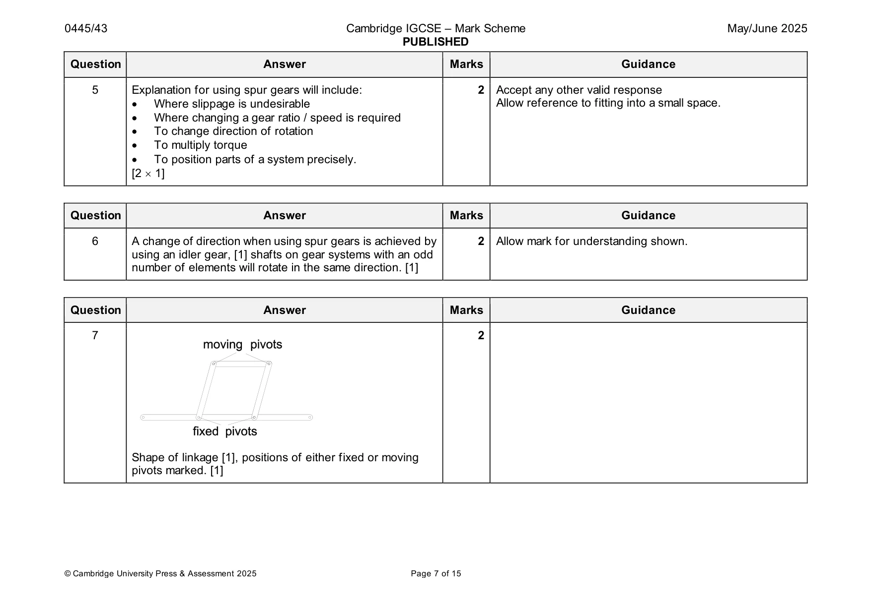
Mark scheme: 5 Explanation for using spur gears will include: 2 Accept any other valid response • Where slippage is undesirable Allow reference to fitting into a small space. • Where changing a gear ratio / speed is required • To change direction of rotation • To multiply torque • To position parts of a system precisely. [2 1]
Q6 · Describe how two shafts can be made to rotate in the same direction using spur gears
6 Describe how two shafts can be made to rotate in the same direction using spur gears. .......................................................................................................................................................... .......................................................................................................................................................... .................................................................................................................................................... [2]
Mark scheme: 6 A change of direction when using spur gears is achieved by 2 Allow mark for understanding shown. using an idler gear, [1] shafts on gear systems with an odd number of elements will rotate in the same direction. [1]
Q7 · Use sketches and notes to show a parallel linkage
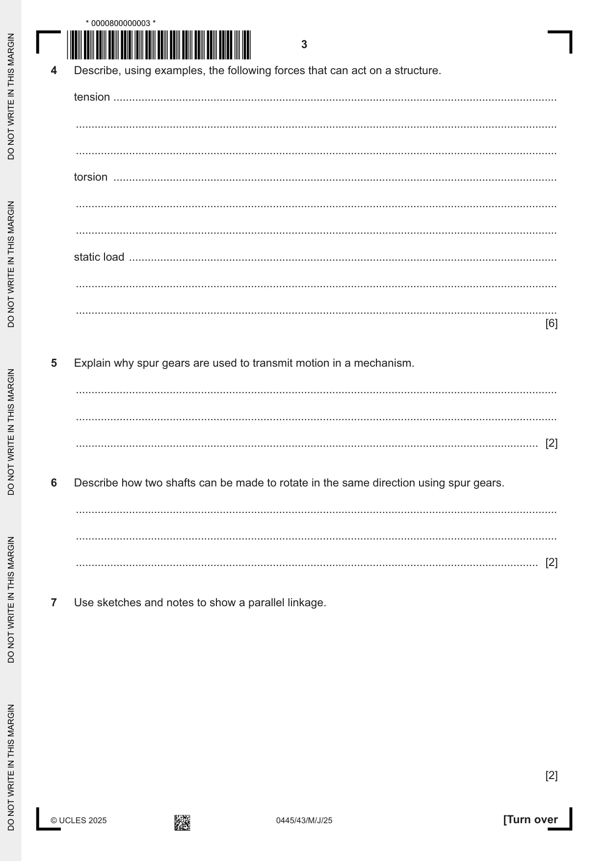
7 Use sketches and notes to show a parallel linkage. [2]
Mark scheme: 7 2 Shape of linkage [1], positions of either fixed or moving pivots marked. [1]
Question 8
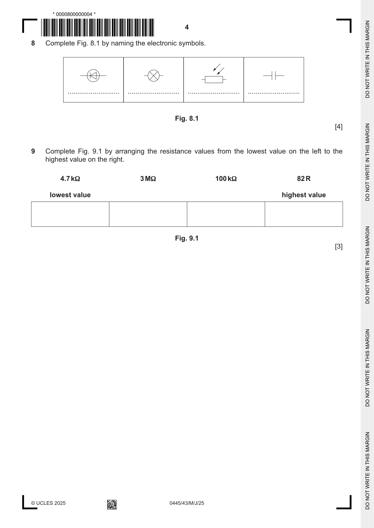
8 Complete Fig. 8.1 by naming the electronic symbols. ........................... ........................... ........................... ........................... Fig. 8.1 [4]
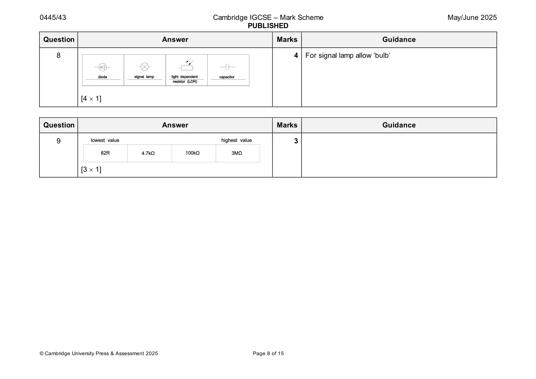
Mark scheme: 8 4 For signal lamp allow ‘bulb’ [4 1]
Question 9
9 Complete Fig. 9.1 by arranging the resistance values from the lowest value on the left to the highest value on the right. 4.7 kΩ 3 MΩ 100 kΩ 82 R lowest value highest value Fig. 9.1 [3]
Mark scheme: 9 3 [3 1]
Q10 · A concrete canopy over the front of a warehouse building
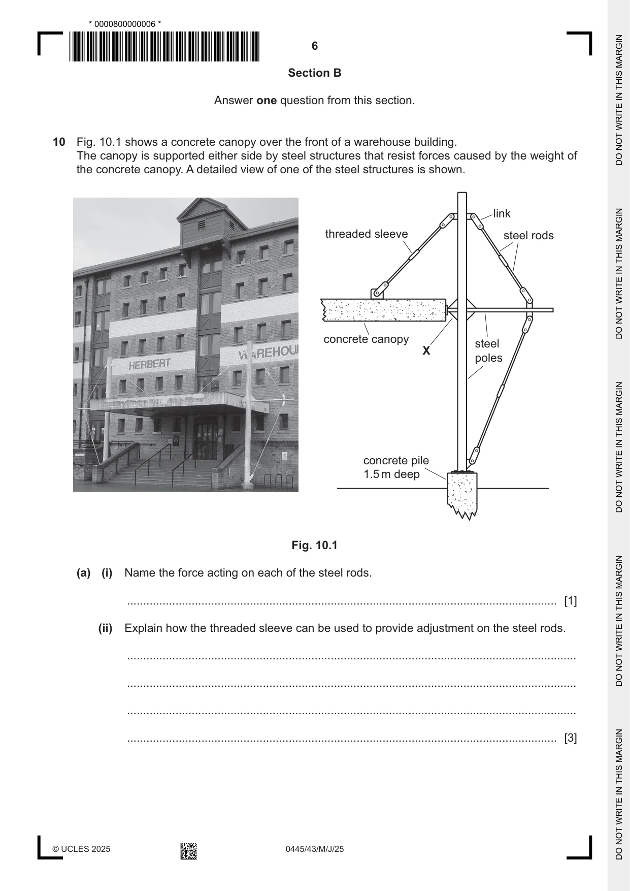
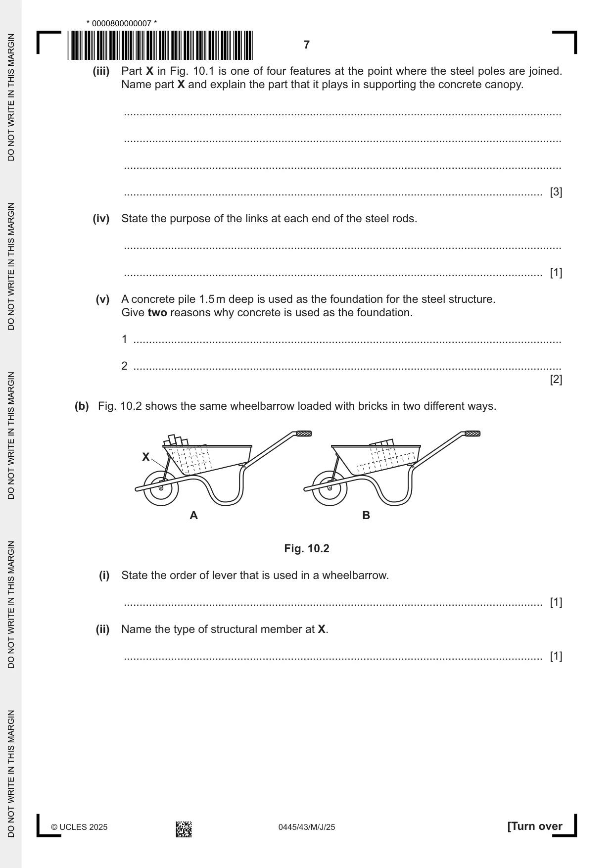
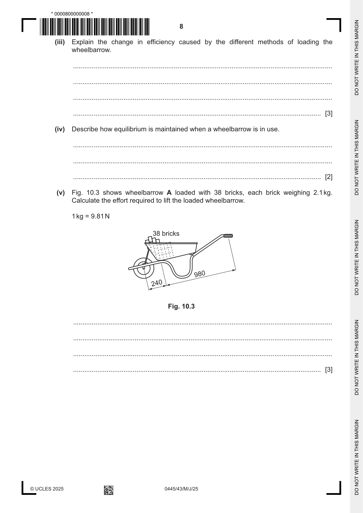
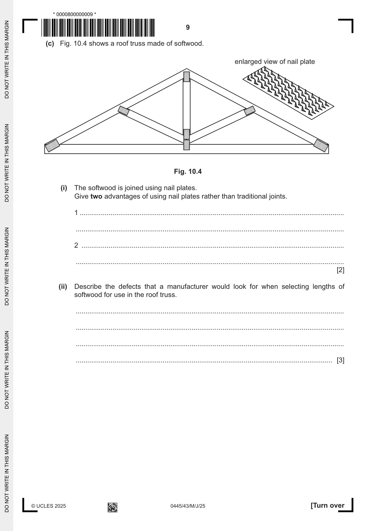
10 Fig. 10.1 shows a concrete canopy over the front of a warehouse building. The canopy is supported either side by steel structures that resist forces caused by the weight of the concrete canopy. A detailed view of one of the steel structures is shown. link threaded sleeve steel rods concrete canopy steel X poles concrete pile 1.5 m deep Fig. 10.1 (a) (i) Name the force acting on each of the steel rods. ..................................................................................................................................... [1] (ii) Explain how the threaded sleeve can be used to provide adjustment on the steel rods. ........................................................................................................................................... ........................................................................................................................................... ........................................................................................................................................... ..................................................................................................................................... [3] (iii) Part X in Fig. 10.1 is one of four features at the point where the steel poles are joined. Name part X and explain the part that it plays in supporting the concrete canopy. ........................................................................................................................................... ........................................................................................................................................... ........................................................................................................................................... ..................................................................................................................................... [3] (iv) State the purpose of the links at each end of the steel rods. ........................................................................................................................................... ..................................................................................................................................... [1] (v) A concrete pile 1.5 m deep is used as the foundation for the steel structure. Give two reasons why concrete is used as the foundation. 1 ........................................................................................................................................ 2 ........................................................................................................................................ [2] (b) Fig. 10.2 shows the same wheelbarrow loaded with bricks in two different ways. X A B Fig. 10.2 (i) State the order of lever that is used in a wheelbarrow. ..................................................................................................................................... [1] (ii) Name the type of structural member at X. ..................................................................................................................................... [1] (iii) Explain the change in efficiency caused by the different methods of loading the wheelbarrow. ........................................................................................................................................... ........................................................................................................................................... ........................................................................................................................................... ..................................................................................................................................... [3] (iv) Describe how equilibrium is maintained when a wheelbarrow is in use. ........................................................................................................................................... ........................................................................................................................................... ..................................................................................................................................... [2] (v) Fig. 10.3 shows wheelbarrow A loaded with 38 bricks, each brick weighing 2.1 kg. Calculate the effort required to lift the loaded wheelbarrow. 1 kg = 9.81 N 38 bricks 980 240 Fig. 10.3 ........................................................................................................................................... ........................................................................................................................................... ........................................................................................................................................... ..................................................................................................................................... [3] (c) Fig. 10.4 shows a roof truss made of softwood. enlarged view of nail plate Fig. 10.4 (i) The softwood is joined using nail plates. Give two advantages of using nail plates rather than traditional joints. 1 ......................................................................................................................................... ........................................................................................................................................... 2 ........................................................................................................................................ ........................................................................................................................................... [2] (ii) Describe the defects that a manufacturer would look for when selecting lengths of softwood for use in the roof truss. ........................................................................................................................................... ........................................................................................................................................... ........................................................................................................................................... ..................................................................................................................................... [3]
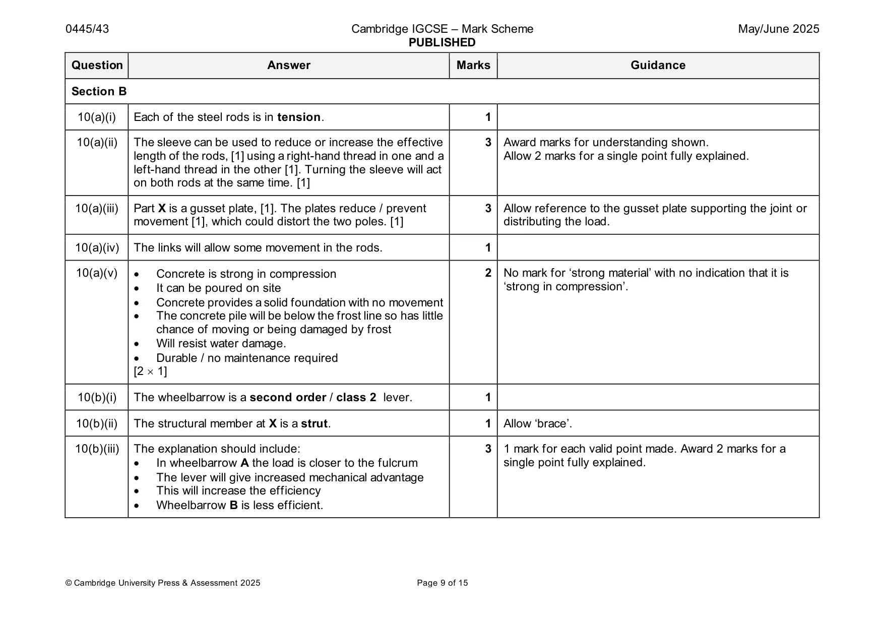
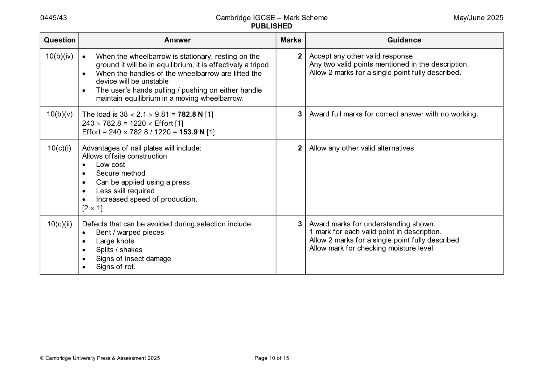
Mark scheme: 10(a)(i) Each of the steel rods is in tension. 1 10(a)(ii) The sleeve can be used to reduce or increase the effective 3 Award marks for understanding shown. length of the rods, [1] using a right-hand thread in one and a Allow 2 marks for a single point fully explained. left-hand thread in the other [1]. Turning the sleeve will act on both rods at the same time. [1] 10(a)(iii) Part X is a gusset plate, [1]. The plates reduce / prevent 3 Allow reference to the gusset plate supporting the joint or movement [1], which could distort the two poles. [1] distributing the load. 10(a)(iv) The links will allow some movement in the rods. 1 10(a)(v) • Concrete is strong in compression 2 No mark for ‘strong material’ with no indication that it is • It can be poured on site ‘strong in compression’. • Concrete provides a solid foundation with no movement • The concrete pile will be below the frost line so has little chance of moving or being damaged by frost • Will resist water damage. • Durable / no maintenance required [2 1] 10(b)(i) The wheelbarrow is a second order / class 2 lever. 1 10(b)(ii) The structural member at X is a strut. 1 Allow ‘brace’. 10(b)(iii) The explanation should include: 3 1 mark for each valid point made. Award 2 marks for a • In wheelbarrow A the load is closer to the fulcrum single point fully explained. • The lever will give increased mechanical advantage • This will increase the efficiency • Wheelbarrow B is less efficient. 10(b)(iv) • When the wheelbarrow is stationary, resting on the 2 Accept any other valid response ground it will be in equilibrium, it is effectively a tripod Any two valid points mentioned in the description. • When the handles of the wheelbarrow are lifted the Allow 2 marks for a single point fully described. device will be unstable • The user’s hands pulling / pushing on either handle maintain equilibrium in a moving wheelbarrow. 10(b)(v) The load is 38 2.1 9.81 = 782.8 N [1] 3 Award full marks for correct answer with no working. 240 782.8 = 1220 Effort [1] Effort = 240 782.8 / 1220 = 153.9 N [1] 10(c)(i) Advantages of nail plates will include: 2 Allow any other valid alternatives Allows offsite construction • Low cost • Secure method • Can be applied using a press • Less skill required • Increased speed of production. [2 1] 10(c)(ii) Defects that can be avoided during selection include: 3 Award marks for understanding shown. • Bent / warped pieces 1 mark for each valid point in description. • Large knots Allow 2 marks for a single point fully described • Splits / shakes Allow mark for checking moisture level. • Signs of insect damage • Signs of rot.
Q11 · Two views of a badge-making machine which is used to press a clear plastic sheet over a…
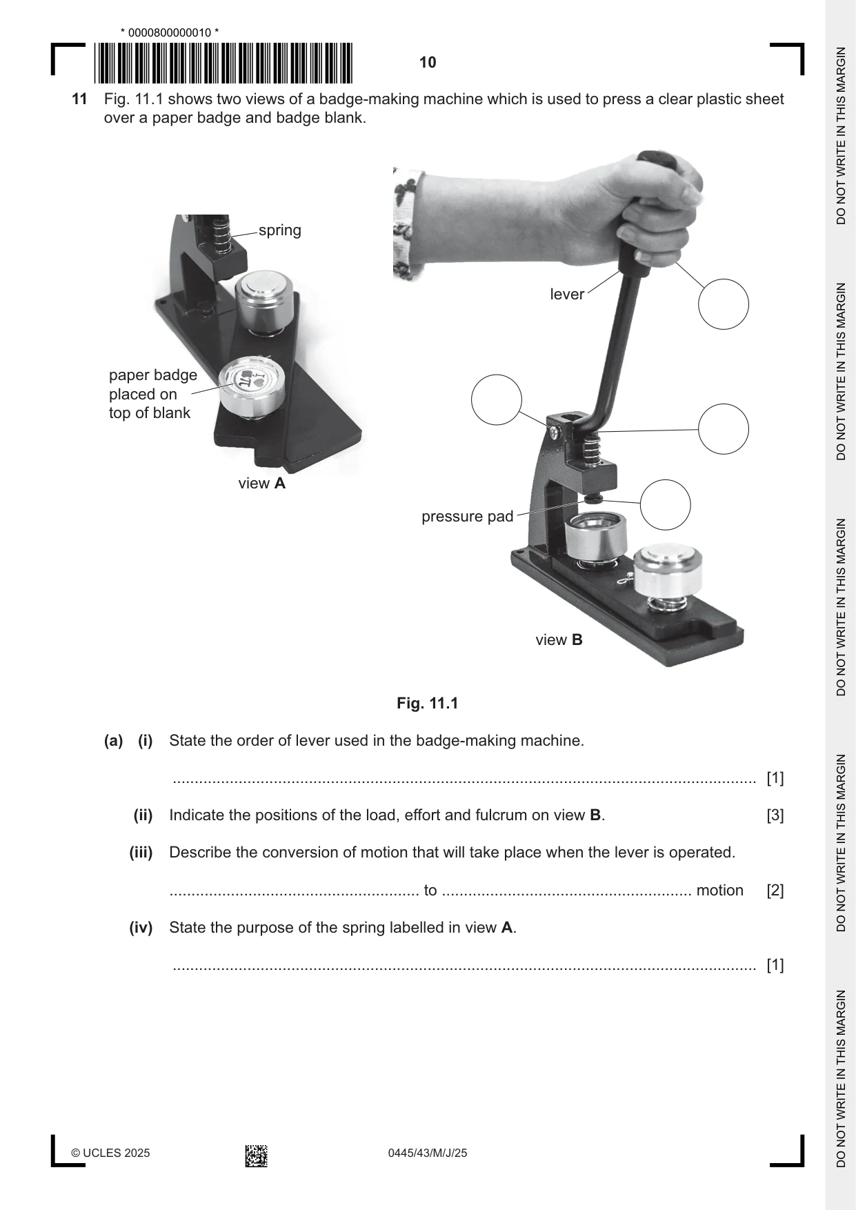
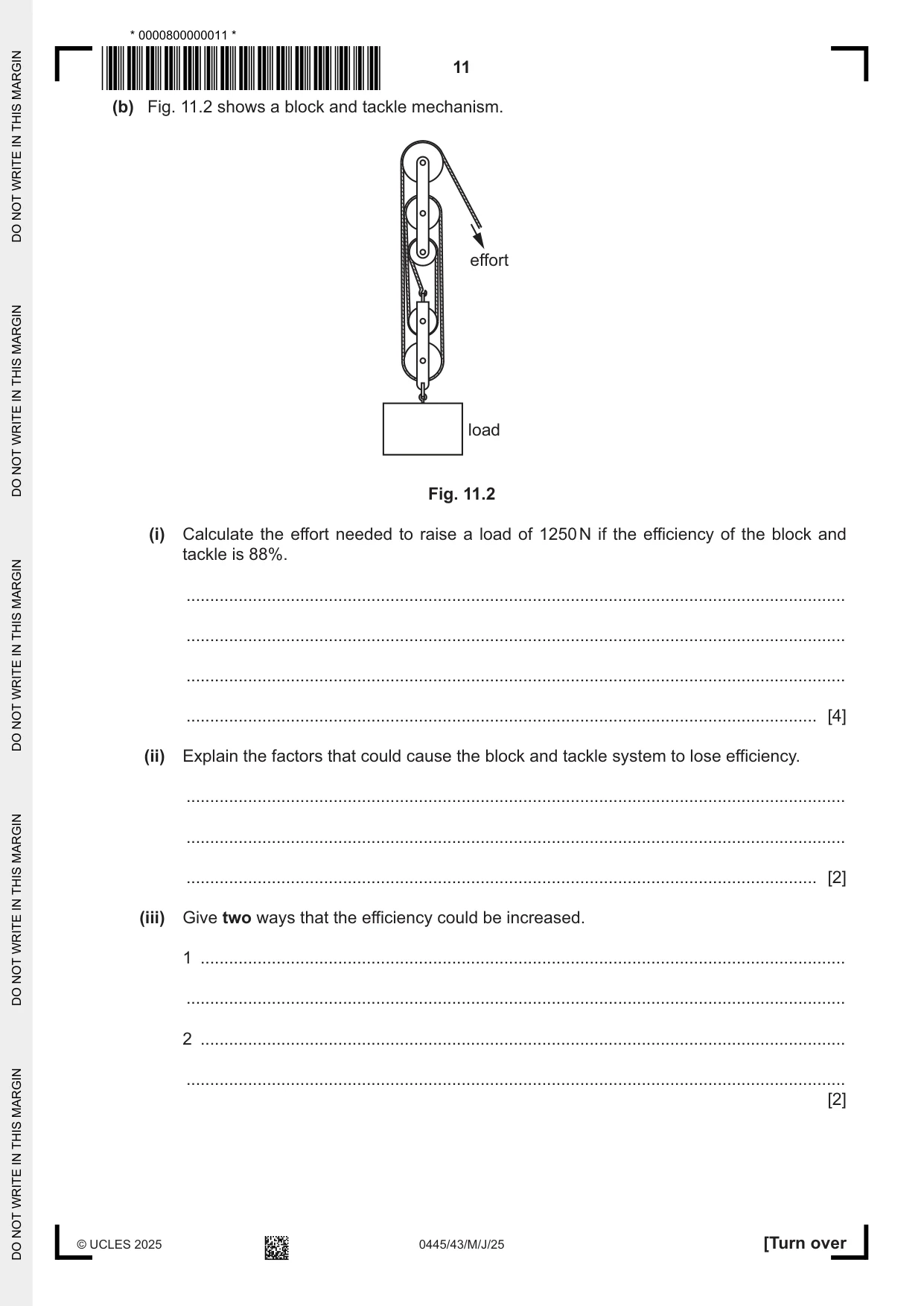
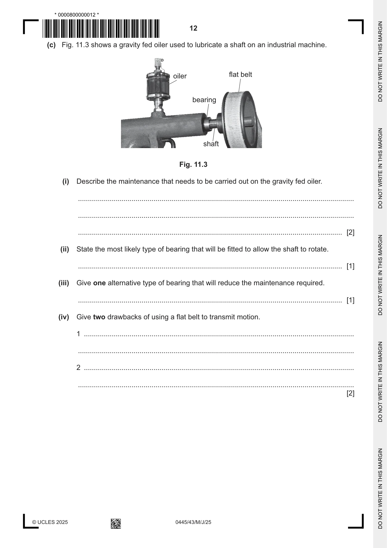
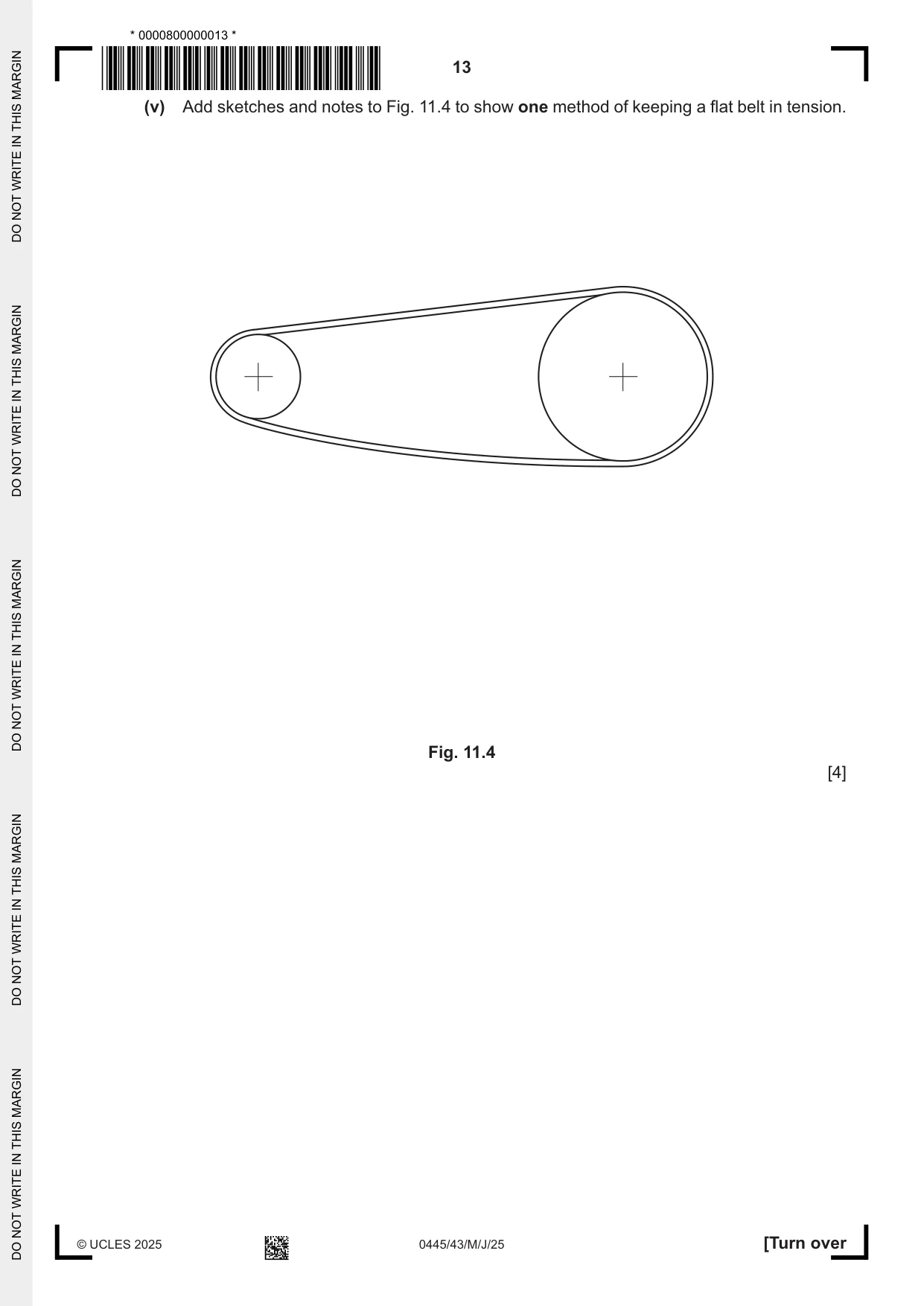
11 Fig. 11.1 shows two views of a badge-making machine which is used to press a clear plastic sheet over a paper badge and badge blank. spring lever paper badge placed on top of blank view A pressure pad view B Fig. 11.1 (a) (i) State the order of lever used in the badge-making machine. ..................................................................................................................................... [1] (ii) Indicate the positions of the load, effort and fulcrum on view B. [3] (iii) Describe the conversion of motion that will take place when the lever is operated. ......................................................... to ......................................................... motion [2] (iv) State the purpose of the spring labelled in view A. ..................................................................................................................................... [1] (b) Fig. 11.2 shows a block and tackle mechanism. effort load Fig. 11.2 (i) Calculate the effort needed to raise a load of 1250 N if the efficiency of the block and tackle is 88%. ........................................................................................................................................... ........................................................................................................................................... ........................................................................................................................................... ..................................................................................................................................... [4] (ii) Explain the factors that could cause the block and tackle system to lose efficiency. ........................................................................................................................................... ........................................................................................................................................... ..................................................................................................................................... [2] (iii) Give two ways that the efficiency could be increased. 1 ........................................................................................................................................ ........................................................................................................................................... 2 ........................................................................................................................................ ........................................................................................................................................... [2] (c) Fig. 11.3 shows a gravity fed oiler used to lubricate a shaft on an industrial machine. oiler flat belt bearing shaft Fig. 11.3 (i) Describe the maintenance that needs to be carried out on the gravity fed oiler. ........................................................................................................................................... ........................................................................................................................................... ..................................................................................................................................... [2] (ii) State the most likely type of bearing that will be fitted to allow the shaft to rotate. ..................................................................................................................................... [1] (iii) Give one alternative type of bearing that will reduce the maintenance required. ..................................................................................................................................... [1] (iv) Give two drawbacks of using a flat belt to transmit motion. 1 ........................................................................................................................................ ........................................................................................................................................... 2 ........................................................................................................................................ ........................................................................................................................................... [2] (v) Add sketches and notes to Fig. 11.4 to show one method of keeping a flat belt in tension. Fig. 11.4 [4]
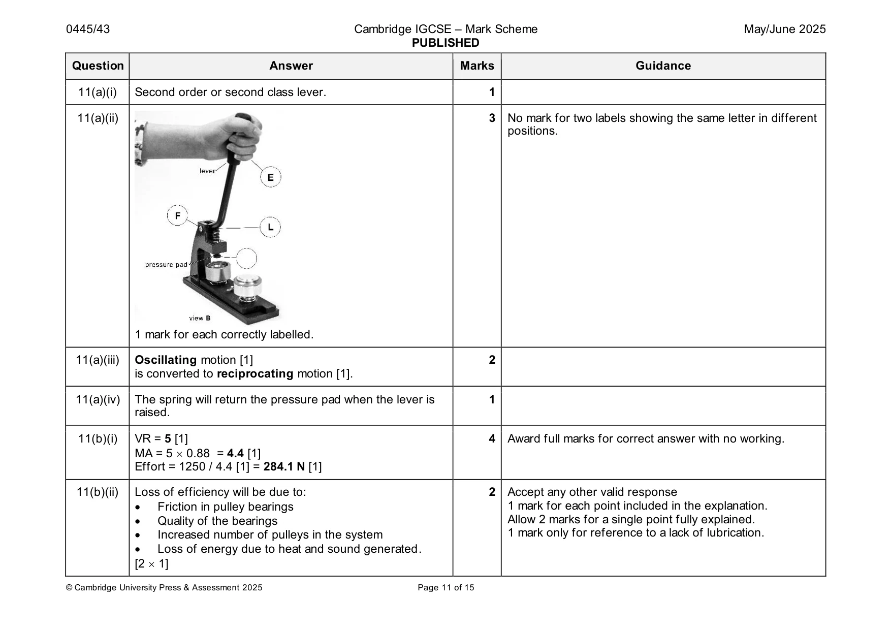
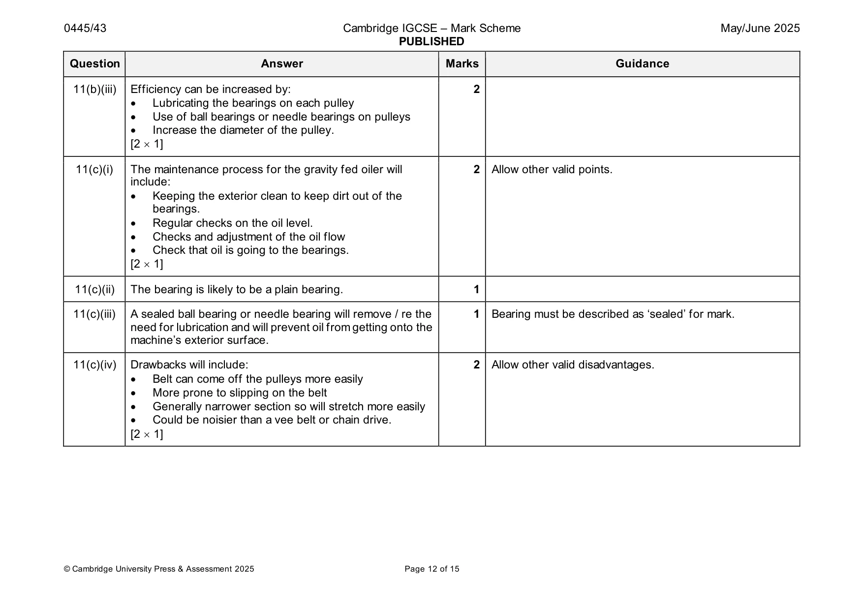
Mark scheme: 11(a)(i) Second order or second class lever. 1 11(a)(ii) 3 No mark for two labels showing the same letter in different positions. 1 mark for each correctly labelled. 11(a)(iii) Oscillating motion [1] 2 is converted to reciprocating motion [1]. 11(a)(iv) The spring will return the pressure pad when the lever is 1 raised. 11(b)(i) VR = 5 [1] 4 Award full marks for correct answer with no working. MA = 5 0.88 = 4.4 [1] Effort = 1250 / 4.4 [1] = 284.1 N [1] 11(b)(ii) Loss of efficiency will be due to: 2 Accept any other valid response • Friction in pulley bearings 1 mark for each point included in the explanation. • Quality of the bearings Allow 2 marks for a single point fully explained. • Increased number of pulleys in the system 1 mark only for reference to a lack of lubrication. • Loss of energy due to heat and sound generated. [2 1] 11(b)(iii) Efficiency can be increased by: 2 • Lubricating the bearings on each pulley • Use of ball bearings or needle bearings on pulleys • Increase the diameter of the pulley. [2 1] 11(c)(i) The maintenance process for the gravity fed oiler will 2 Allow other valid points. include: • Keeping the exterior clean to keep dirt out of the bearings. • Regular checks on the oil level. • Checks and adjustment of the oil flow • Check that oil is going to the bearings. [2 1] 11(c)(ii) The bearing is likely to be a plain bearing. 1 11(c)(iii) A sealed ball bearing or needle bearing will remove / re the 1 Bearing must be described as ‘sealed’ for mark. need for lubrication and will prevent oil from getting onto the machine’s exterior surface. 11(c)(iv) Drawbacks will include: 2 Allow other valid disadvantages. • Belt can come off the pulleys more easily • More prone to slipping on the belt • Generally narrower section so will stretch more easily • Could be noisier than a vee belt or chain drive. [2 1] 11(c)(v) Clear sketches [2] 4 Workable solution [1] Supporting notes [1] The method could be: • A spring tensioned roller pressing against the belt • One of the pulleys being movable, mounted on a slot • One pulley mounted on a quadrant which can be swung down to provide tension.
Q12 · A conveyor belt used to move boxes in a manufacturing unit
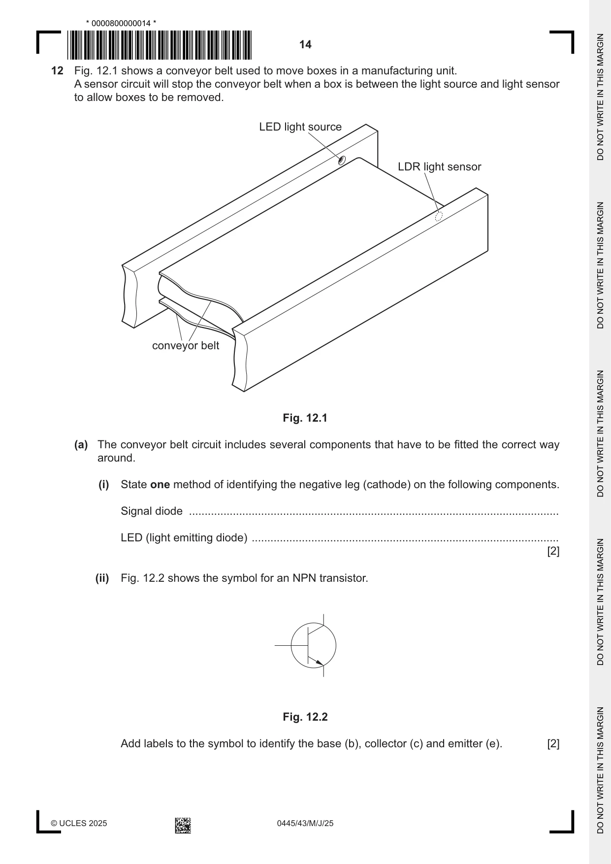
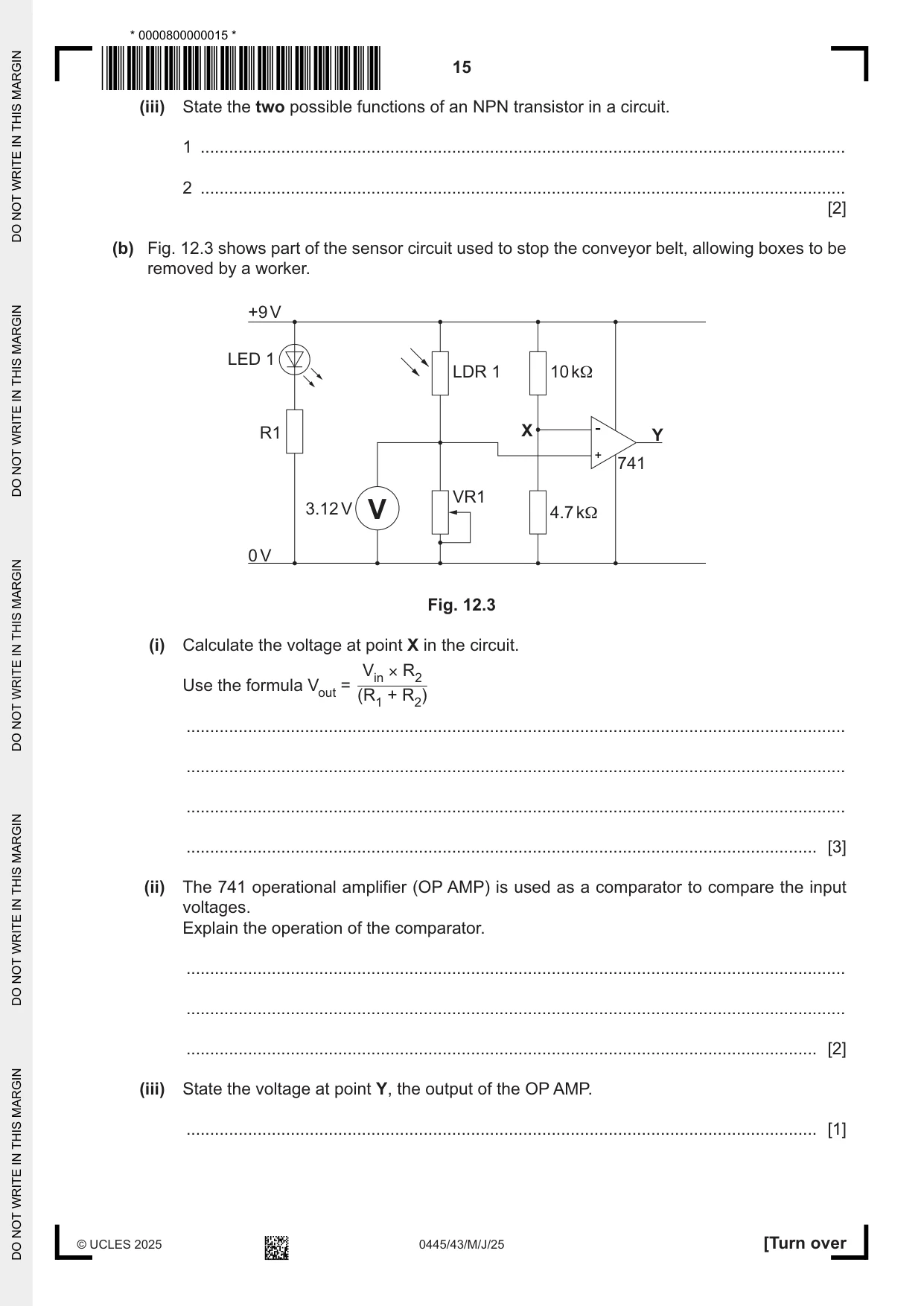
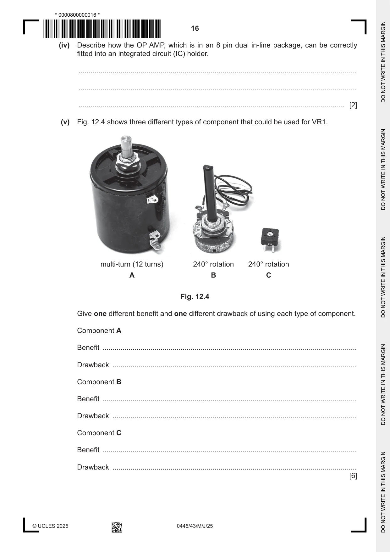
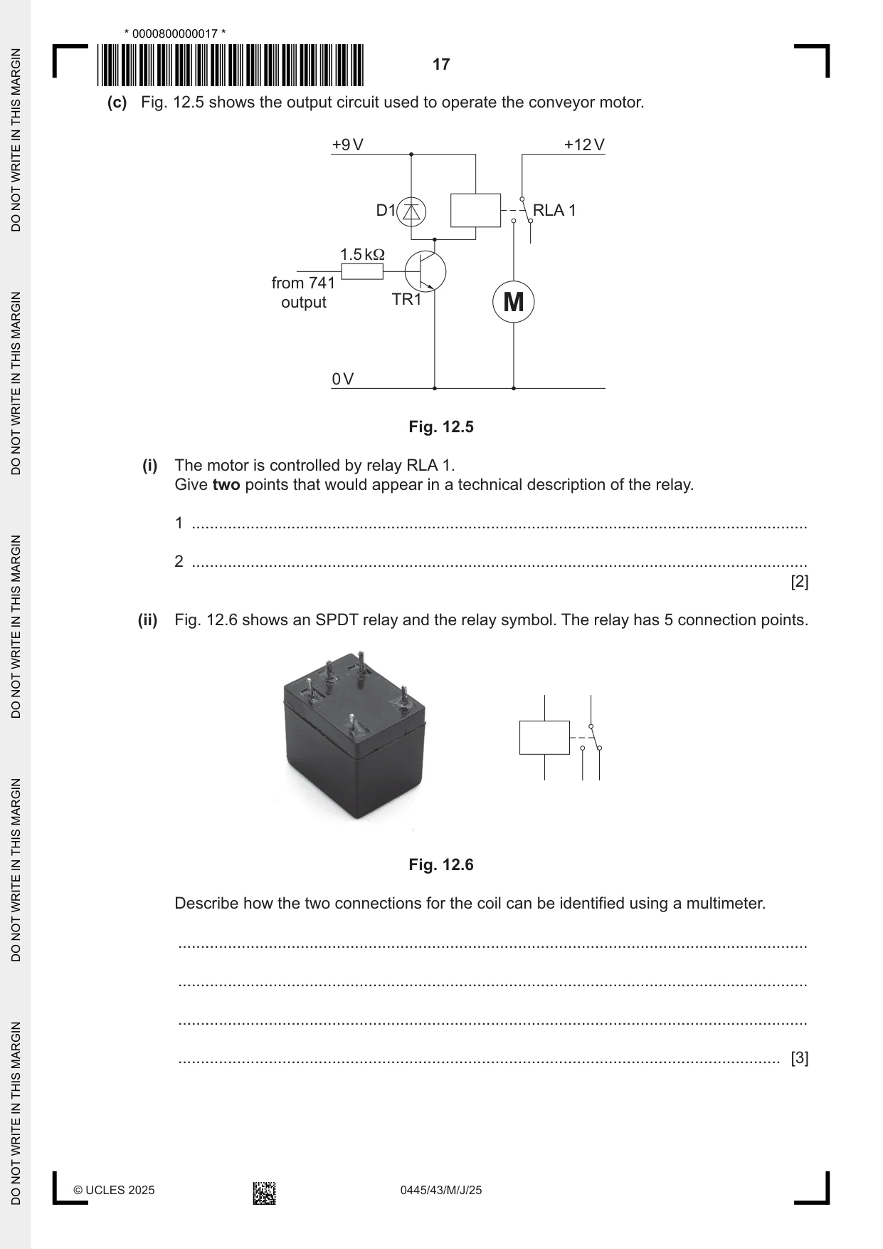
12 Fig. 12.1 shows a conveyor belt used to move boxes in a manufacturing unit. A sensor circuit will stop the conveyor belt when a box is between the light source and light sensor to allow boxes to be removed. LED light source LDR light sensor conveyor belt Fig. 12.1 (a) The conveyor belt circuit includes several components that have to be fitted the correct way around. (i) State one method of identifying the negative leg (cathode) on the following components. Signal diode ...................................................................................................................... LED (light emitting diode) .................................................................................................. [2] (ii) Fig. 12.2 shows the symbol for an NPN transistor. Fig. 12.2 Add labels to the symbol to identify the base (b), collector (c) and emitter (e). [2] (iii) State the two possible functions of an NPN transistor in a circuit. 1 ........................................................................................................................................ 2 ........................................................................................................................................ [2] (b) Fig. 12.3 shows part of the sensor circuit used to stop the conveyor belt, allowing boxes to be removed by a worker. +9 V LED 1 LDR 1 10 kΩ R1 X - Y + 741 VR1 3.12 V V 4.7 kΩ 0 V Fig. 12.3 (i) Calculate the voltage at point X in the circuit. Vin × R2 Use the formula Vout = + (R1 R2) ........................................................................................................................................... ........................................................................................................................................... ........................................................................................................................................... ..................................................................................................................................... [3] (ii) The 741 operational amplifier (OP AMP) is used as a comparator to compare the input voltages. Explain the operation of the comparator. ........................................................................................................................................... ........................................................................................................................................... ..................................................................................................................................... [2] (iii) State the voltage at point Y, the output of the OP AMP. ..................................................................................................................................... [1] (iv) Describe how the OP AMP, which is in an 8 pin dual in-line package, can be correctly fitted into an integrated circuit (IC) holder. ........................................................................................................................................... ........................................................................................................................................... ..................................................................................................................................... [2] (v) Fig. 12.4 shows three different types of component that could be used for VR1. multi-turn (12 turns) 240° rotation 240° rotation A B C Fig. 12.4 Give one different benefit and one different drawback of using each type of component. Component A Benefit ............................................................................................................................... Drawback .......................................................................................................................... Component B Benefit ............................................................................................................................... Drawback .......................................................................................................................... Component C Benefit ............................................................................................................................... Drawback .......................................................................................................................... [6]
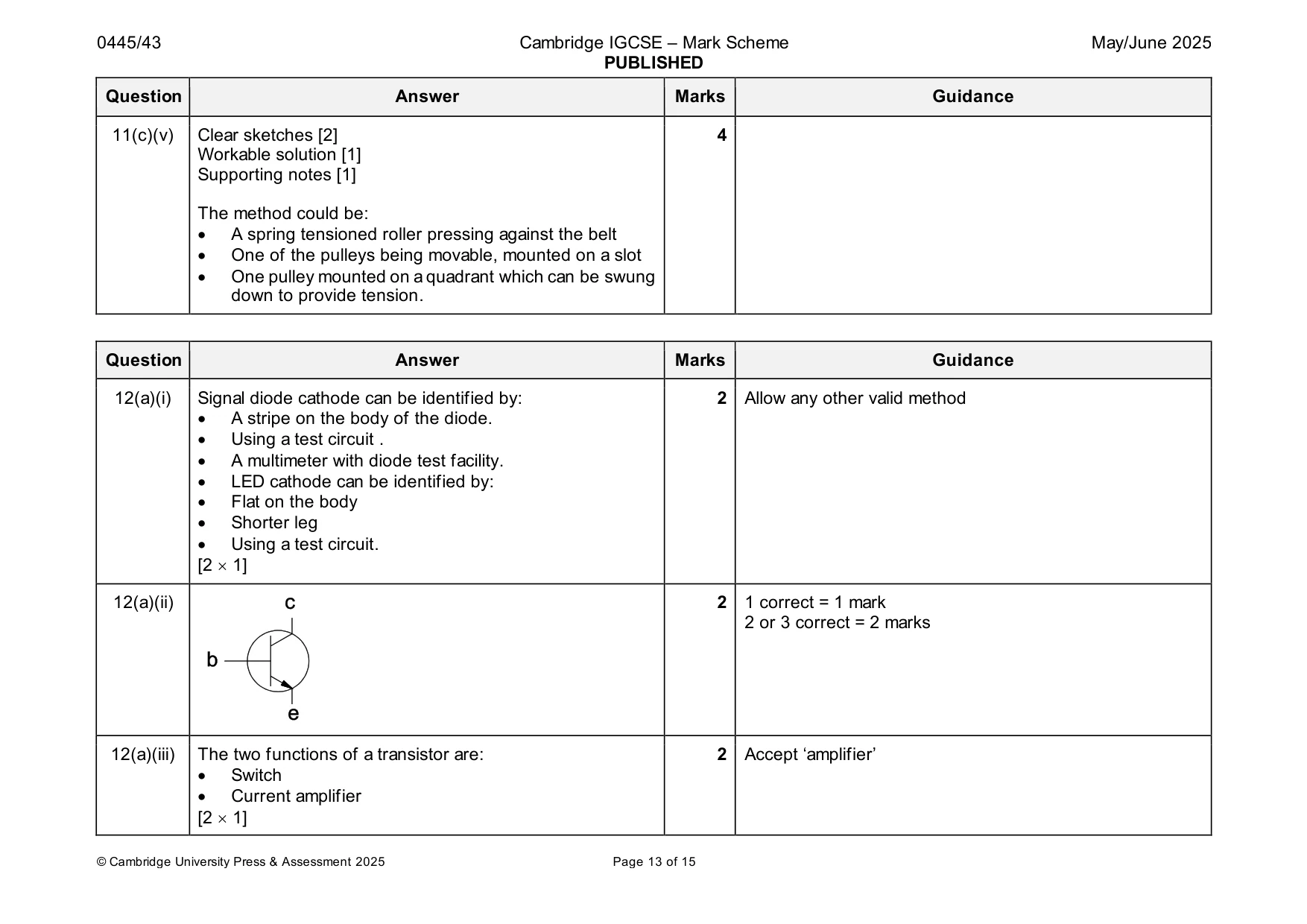
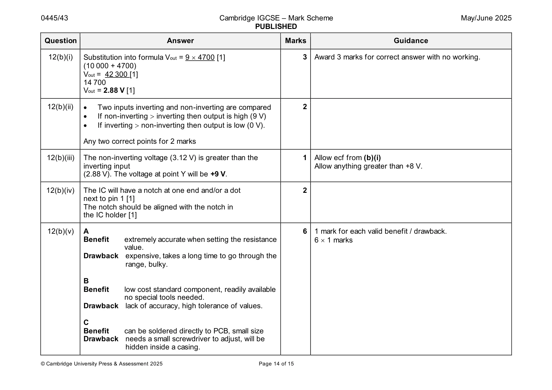
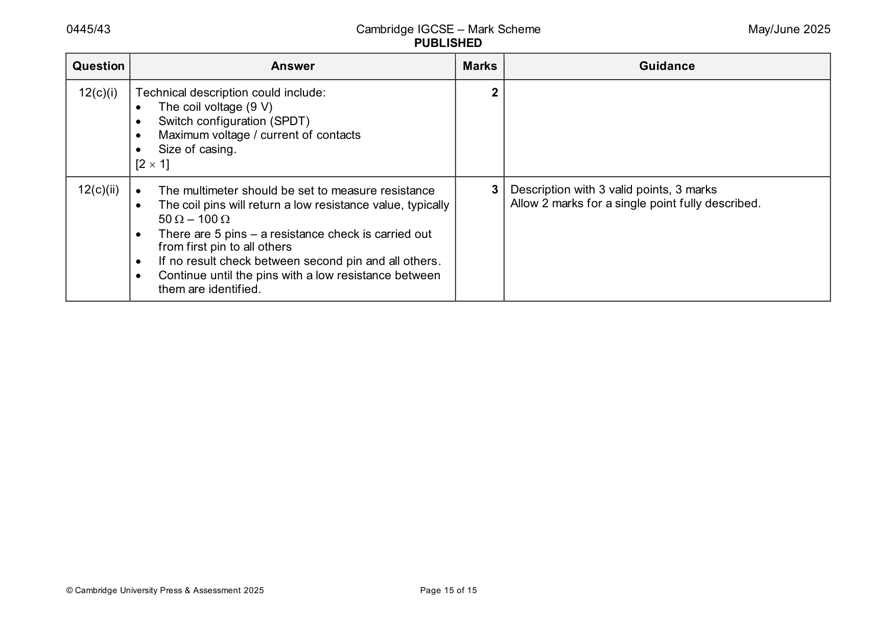
Mark scheme: 12(a)(i) Signal diode cathode can be identified by: 2 Allow any other valid method • A stripe on the body of the diode. • Using a test circuit . • A multimeter with diode test facility. • LED cathode can be identified by: • Flat on the body • Shorter leg • Using a test circuit. [2 1] 12(a)(ii) 2 1 correct = 1 mark 2 or 3 correct = 2 marks 12(a)(iii) The two functions of a transistor are: 2 Accept ‘amplifier’ • Switch • Current amplifier [2 1] 12(b)(i) Substitution into formula Vout = 9 4700 [1] 3 Award 3 marks for correct answer with no working. (10 000 + 4700) Vout = 42 300 [1] 14 700 Vout = 2.88 V [1] 12(b)(ii) • Two inputs inverting and non-inverting are compared 2 • If non-inverting inverting then output is high (9 V) • If inverting non-inverting then output is low (0 V). Any two correct points for 2 marks 12(b)(iii) The non-inverting voltage (3.12 V) is greater than the 1 Allow ecf from (b)(i) inverting input Allow anything greater than +8 V. (2.88 V). The voltage at point Y will be +9 V. 12(b)(iv) The IC will have a notch at one end and/or a dot 2 next to pin 1 [1] The notch should be aligned with the notch in the IC holder [1] 12(b)(v) A 6 1 mark for each valid benefit / drawback. Benefit extremely accurate when setting the resistance 6 1 marks value. Drawback expensive, takes a long time to go through the range, bulky. B Benefit low cost standard component, readily available no special tools needed. Drawback lack of accuracy, high tolerance of values. C Benefit can be soldered directly to PCB, small size Drawback needs a small screwdriver to adjust, will be hidden inside a casing. 12(c)(i) Technical description could include: 2 • The coil voltage (9 V) • Switch configuration (SPDT) • Maximum voltage / current of contacts • Size of casing. [2 1] 12(c)(ii) • The multimeter should be set to measure resistance 3 Description with 3 valid points, 3 marks • The coil pins will return a low resistance value, typically Allow 2 marks for a single point fully described. 50 – 100 • There are 5 pins – a resistance check is carried out from first pin to all others • If no result check between second pin and all others. • Continue until the pins with a low resistance between them are identified.
What was in this paper
The subtopics covered by these 12 questions, and how many questions each got. Open one in a new tab to see every Cambridge question on it.
What you needed in this session
Cambridge’s own grade thresholds for 2025 May/June, Paper 4 · Variant 3. A higher threshold means an easier paper — the bar moves with how the cohort did.