Cambridge IGCSE Design and Technology 0445 — 2024 May/June Paper 4 · Variant 3
0445/43/M/J/24 · 12 questions · 50 marks · 60 min
The question paper and its mark scheme, free to read here and free to download. This is Cambridge’s own paper, exactly as it was sat.
Question paper20 pages
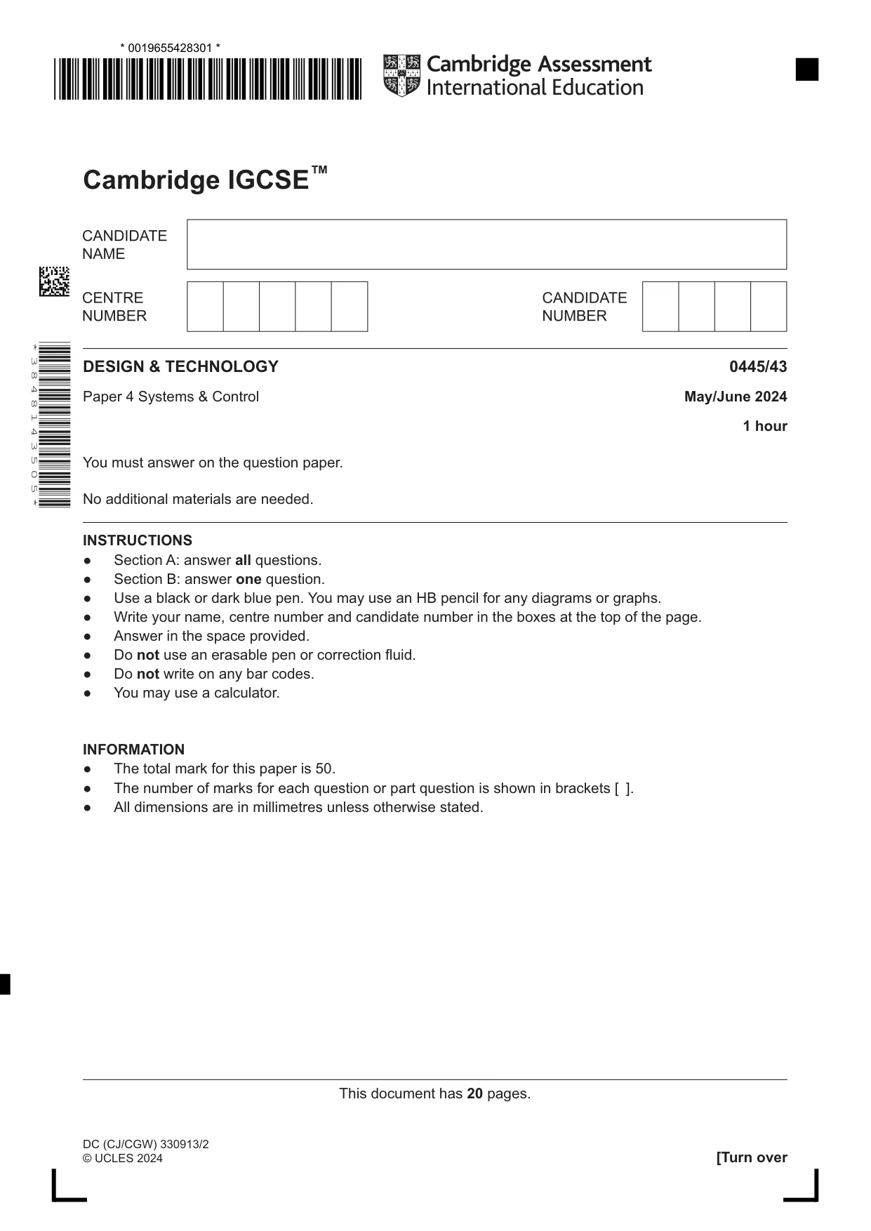
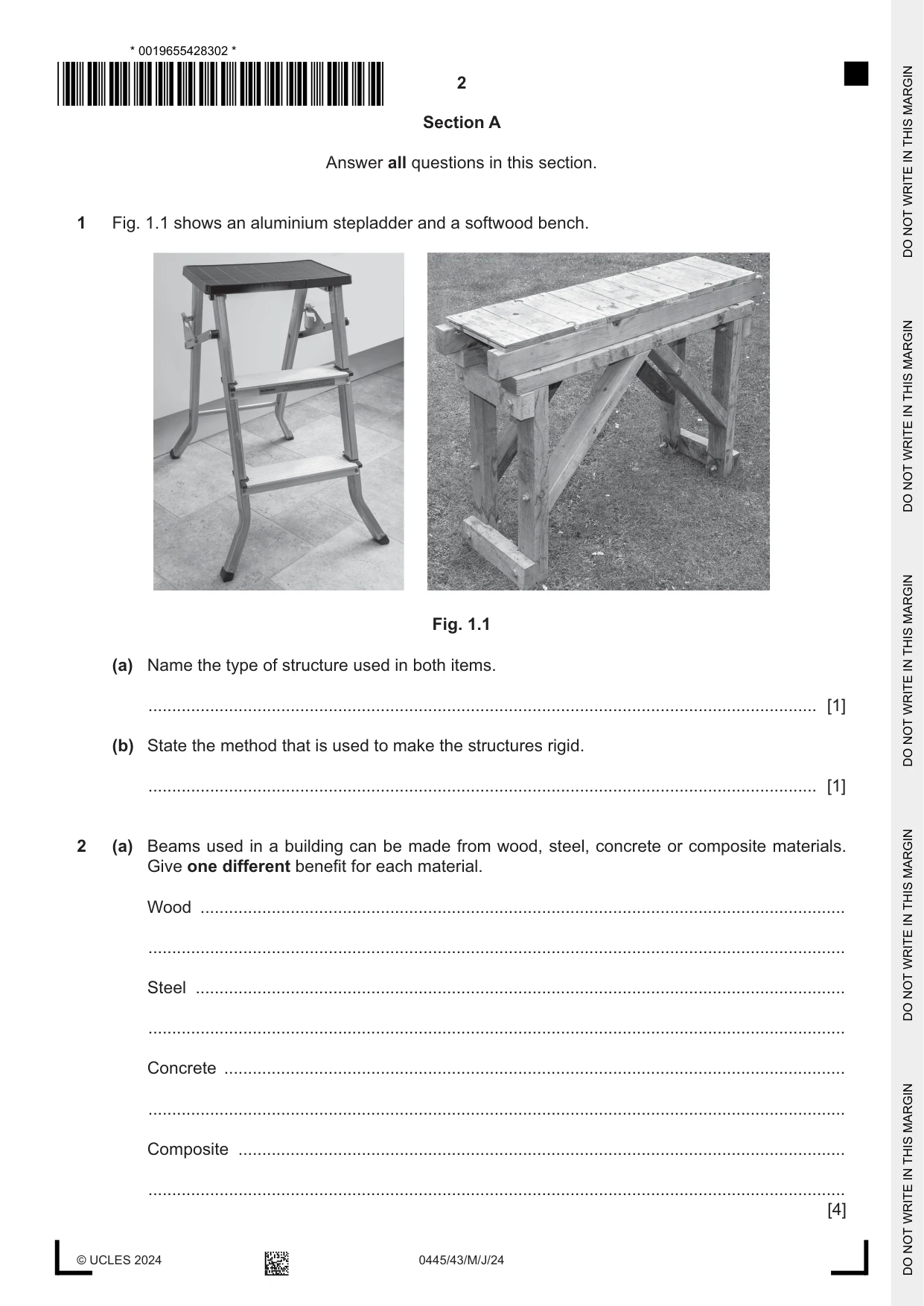
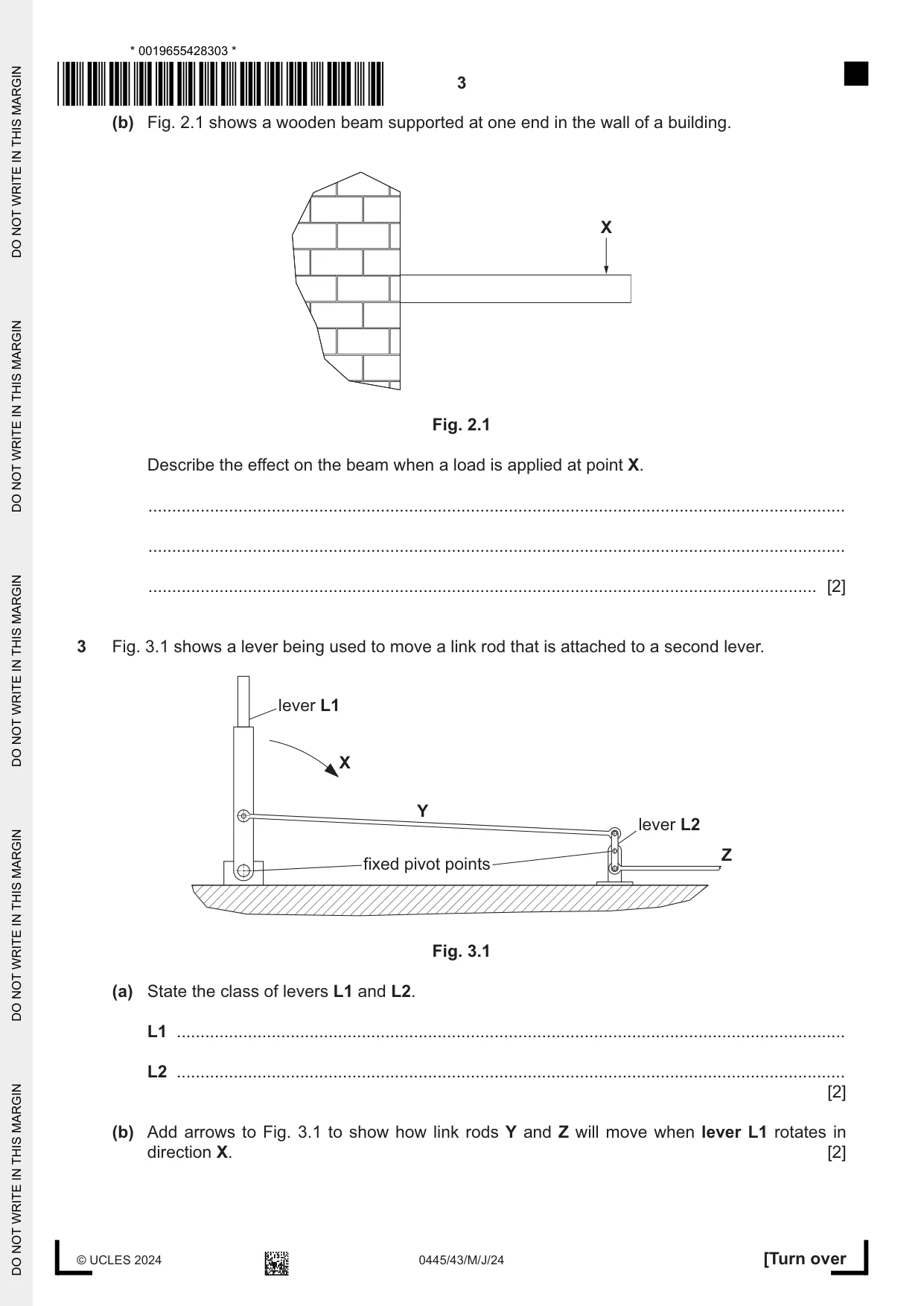
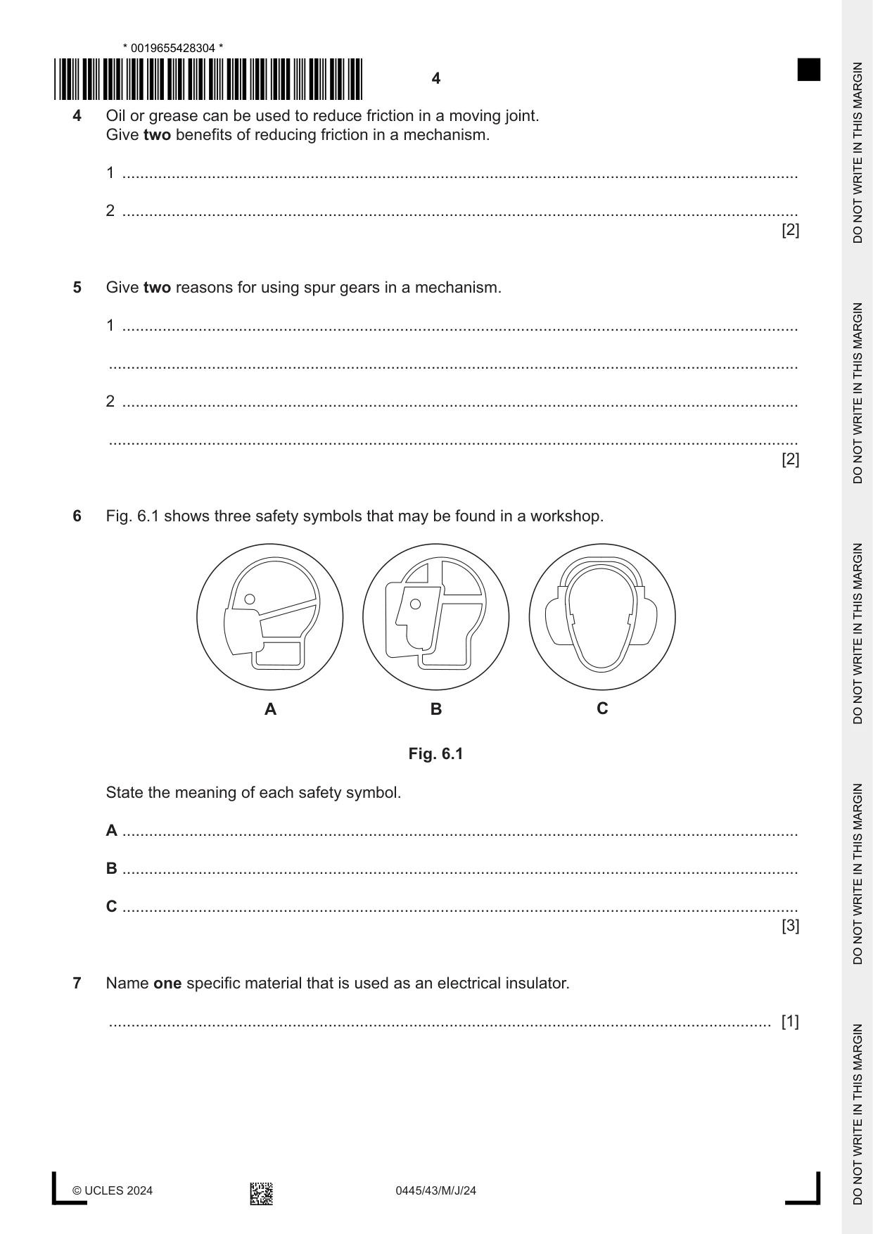
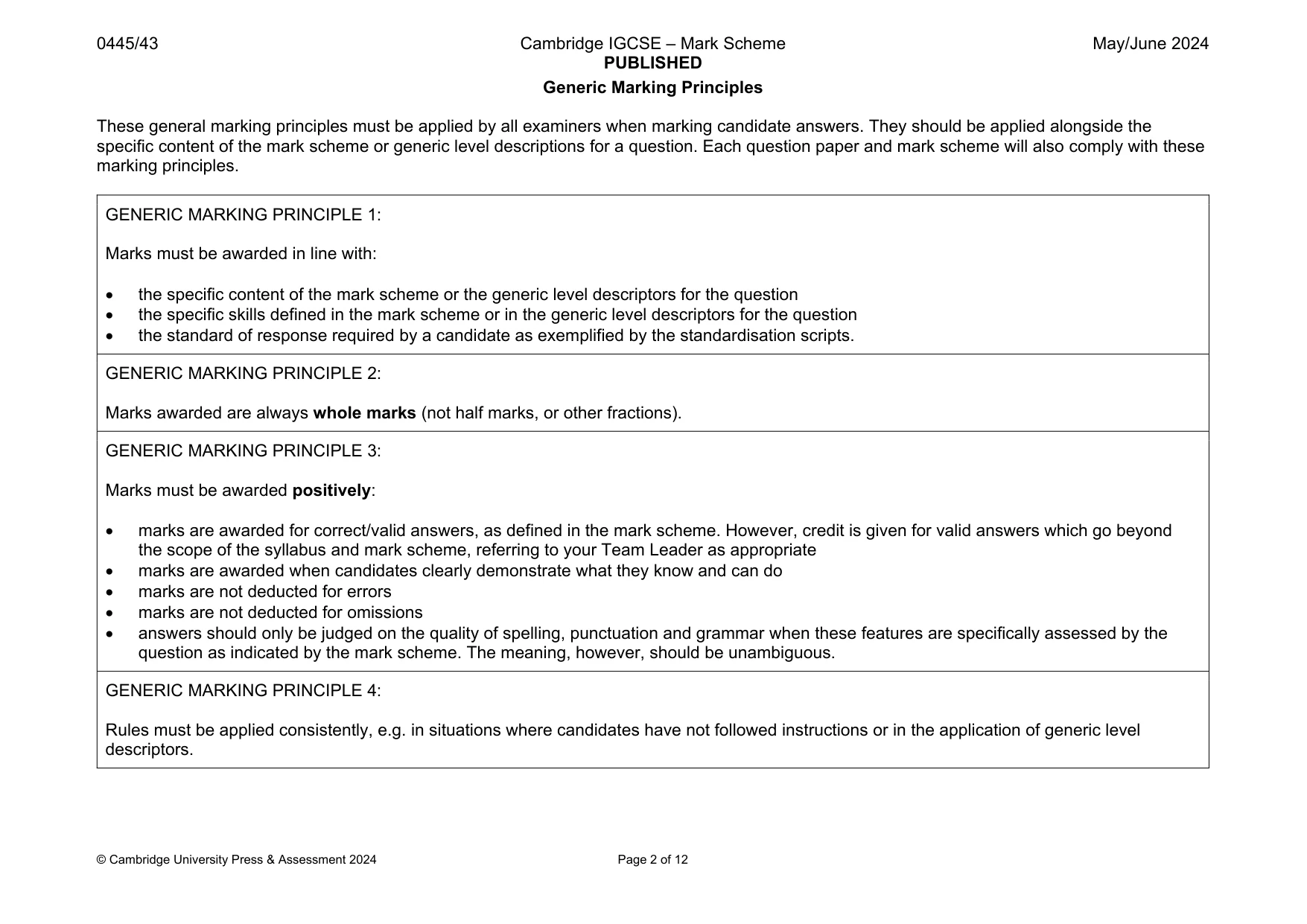
Mark scheme12 pages
Answers below. Sit the paper first if you are practising.
Questions as text
Q1 · An aluminium stepladder and a softwood bench
1 Fig. 1.1 shows an aluminium stepladder and a softwood bench. Fig. 1.1 (a) Name the type of structure used in both items. ............................................................................................................................................. [1] (b) State the method that is used to make the structures rigid. ............................................................................................................................................. [1]
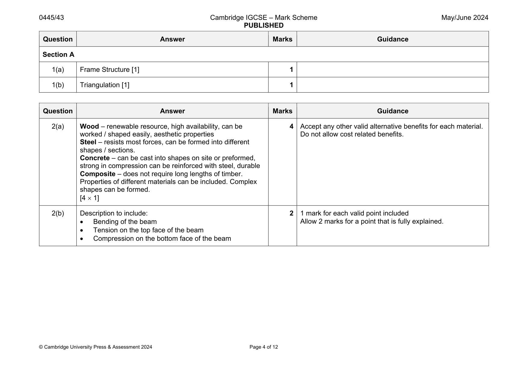
Mark scheme: 1(a) Frame Structure [1] 1 1(b) Triangulation [1] 1
Q2 · Beams used in a building can be made from wood, steel, concrete or composite materials
2 (a) Beams used in a building can be made from wood, steel, concrete or composite materials. Give one different benefit for each material. Wood ........................................................................................................................................ ................................................................................................................................................... Steel ......................................................................................................................................... ................................................................................................................................................... Concrete ................................................................................................................................... ................................................................................................................................................... Composite ................................................................................................................................ ................................................................................................................................................... [4] (b) Fig. 2.1 shows a wooden beam supported at one end in the wall of a building. X Fig. 2.1 Describe the effect on the beam when a load is applied at point X. ................................................................................................................................................... ................................................................................................................................................... ............................................................................................................................................. [2]
Mark scheme: 2(a) Wood – renewable resource, high availability, can be worked / shaped easily, aesthetic properties Steel – resists most forces, can be formed into different shapes / sections. Concrete – can be cast into shapes on site or preformed, strong in compression can be reinforced with steel, durable Composite – does not require long lengths of timber. Properties of different materials can be included. Complex shapes can be formed. [4 1] Do not allow cost related benefits. 2(b) Description to include: Bending of the beam Tension on the top face of the beam Compression on the bottom face of the beam 2 1 mark for each valid point included Allow 2 marks for a point that is fully explained.
Q3 · A lever being used to move a link rod that is attached to a second lever
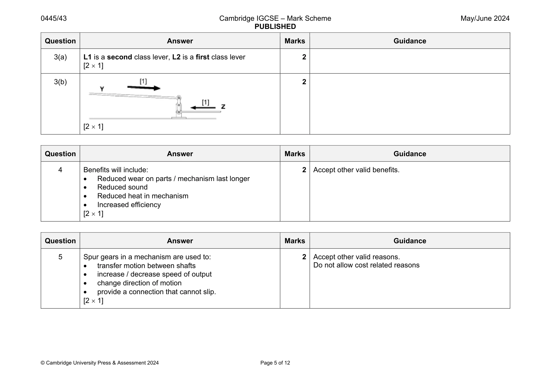
3 Fig. 3.1 shows a lever being used to move a link rod that is attached to a second lever. lever L1 X Y lever L2 Z fixed pivot points Fig. 3.1 (a) State the class of levers L1 and L2. L1 ............................................................................................................................................. L2 ............................................................................................................................................. [2] (b) Add arrows to Fig. 3.1 to show how link rods Y and Z will move when lever L1 rotates in direction X. [2]
Mark scheme: 3(a) L1 is a second class lever, L2 is a first class lever [2 1] 2 3(b) [2 1] 2
Q4 · Oil or grease can be used to reduce friction in a moving joint
4 Oil or grease can be used to reduce friction in a moving joint. Give two benefits of reducing friction in a mechanism. 1 ....................................................................................................................................................... 2 ....................................................................................................................................................... [2]
Mark scheme: 4 Benefits will include: Reduced wear on parts / mechanism last longer Reduced sound Reduced heat in mechanism Increased efficiency [2 1]
Q5 · Give two reasons for using spur gears in a mechanism
5 Give two reasons for using spur gears in a mechanism. 1 ....................................................................................................................................................... .......................................................................................................................................................... 2 ....................................................................................................................................................... .......................................................................................................................................................... [2]
Mark scheme: 5 Spur gears in a mechanism are used to: transfer motion between shafts increase / decrease speed of output change direction of motion provide a connection that cannot slip. [2 1] Do not allow cost related reasons
Q6 · Three safety symbols that may be found in a workshop
6 Fig. 6.1 shows three safety symbols that may be found in a workshop. A B C Fig. 6.1 State the meaning of each safety symbol. A ....................................................................................................................................................... B ....................................................................................................................................................... C ....................................................................................................................................................... [3]
Mark scheme: 6 A – Face covering should be worn [1] B – Face shield should be worn [1] C – Ear protection should be worn [1] 3 Allow marks if reason for using device is given.
Q7 · Name one specific material that is used as an electrical insulator
7 Name one specific material that is used as an electrical insulator. .................................................................................................................................................... [1]
Mark scheme: 7 Any named electrical insulating material, [1] e.g. PVC, urea formaldehyde, melamine formaldehyde, rubber, ceramic 1 Do not allow plastic, thermoplastic or thermoset plastic.
Q8 · Complete Table 8.1 by circling the correct unit used to measure different electrical…
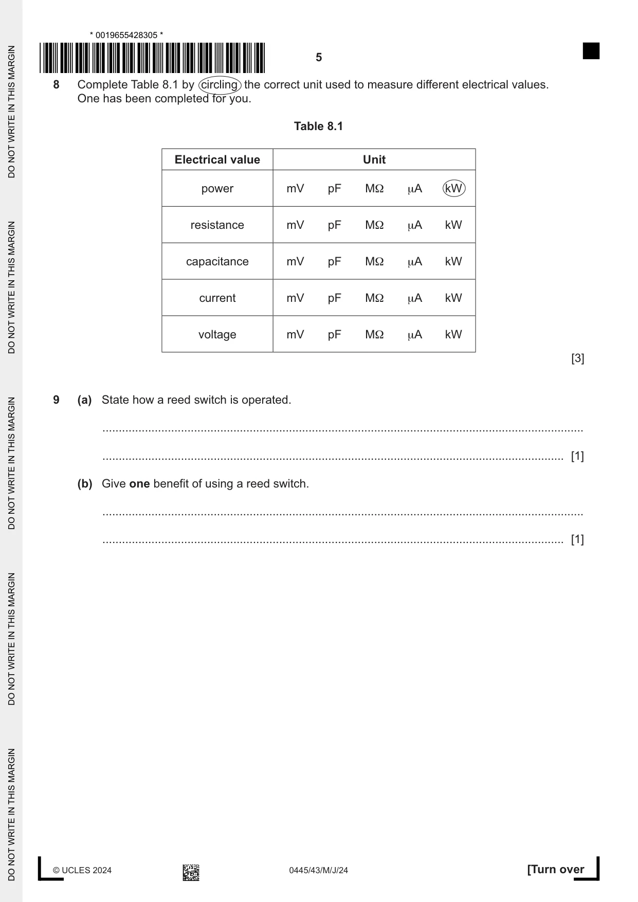
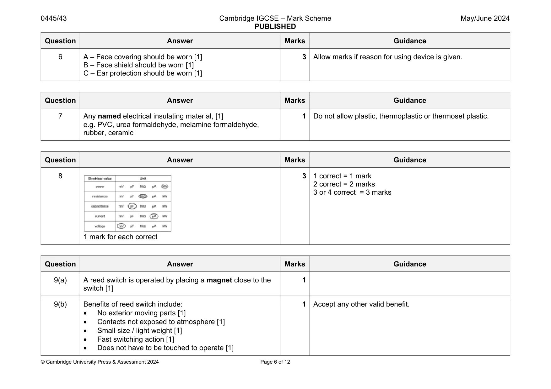
8 Complete Table 8.1 by circling the correct unit used to measure different electrical values. One has been completed for you. Table 8.1 Electrical value Unit power mV pF MΩ μA kW resistance mV pF MΩ μA kW capacitance mV pF MΩ μA kW current mV pF MΩ μA kW voltage mV pF MΩ μA kW [3]
Mark scheme: 8 1 mark for each correct 3 1 correct = 1 mark 2 correct = 2 marks 3 or 4 correct = 3 marks
Q9 · State how a reed switch is operated
9 (a) State how a reed switch is operated. ................................................................................................................................................... ............................................................................................................................................. [1] (b) Give one benefit of using a reed switch. ................................................................................................................................................... ............................................................................................................................................. [1]
Mark scheme: 9(a) A reed switch is operated by placing a magnet close to the switch [1] 1 9(b) Benefits of reed switch include: No exterior moving parts [1] Contacts not exposed to atmosphere [1] Small size / light weight [1] Fast switching action [1] Does not have to be touched to operate [1] 1 Accept any other valid benefit.
Q10 · Concrete is commonly used in structures
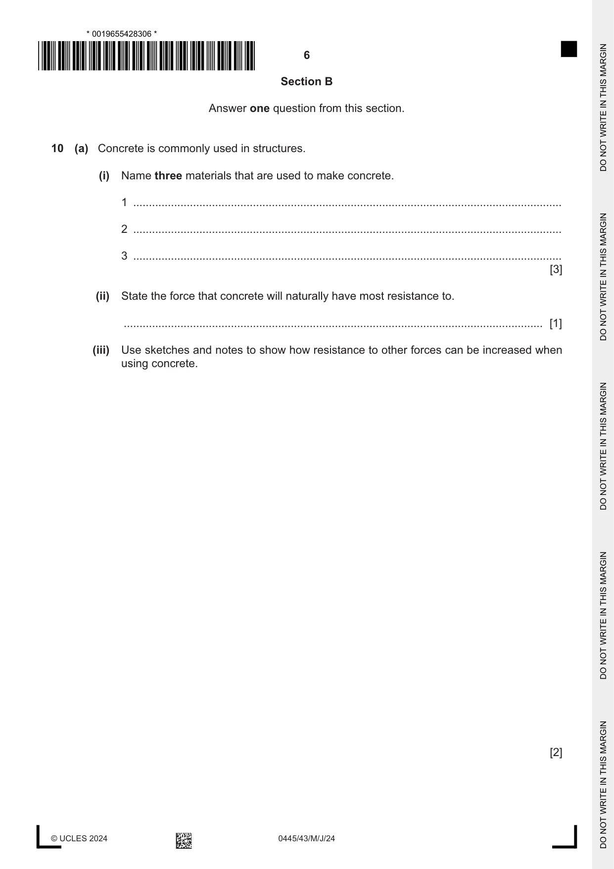
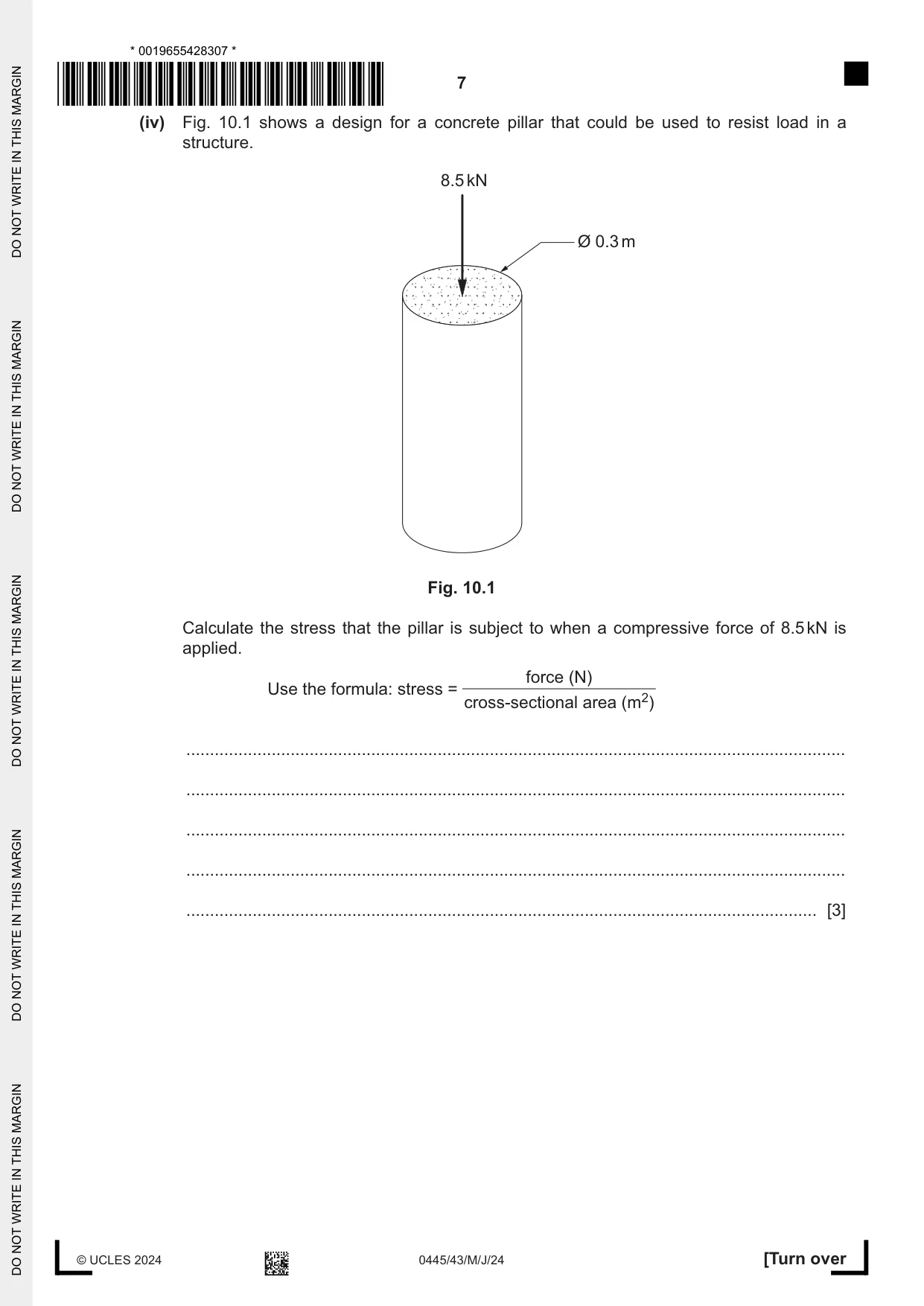
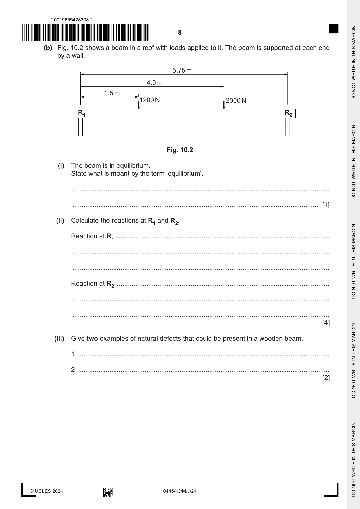
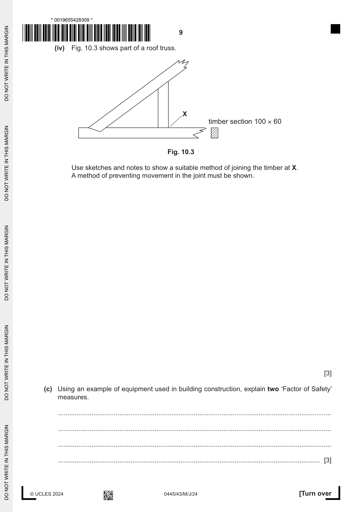
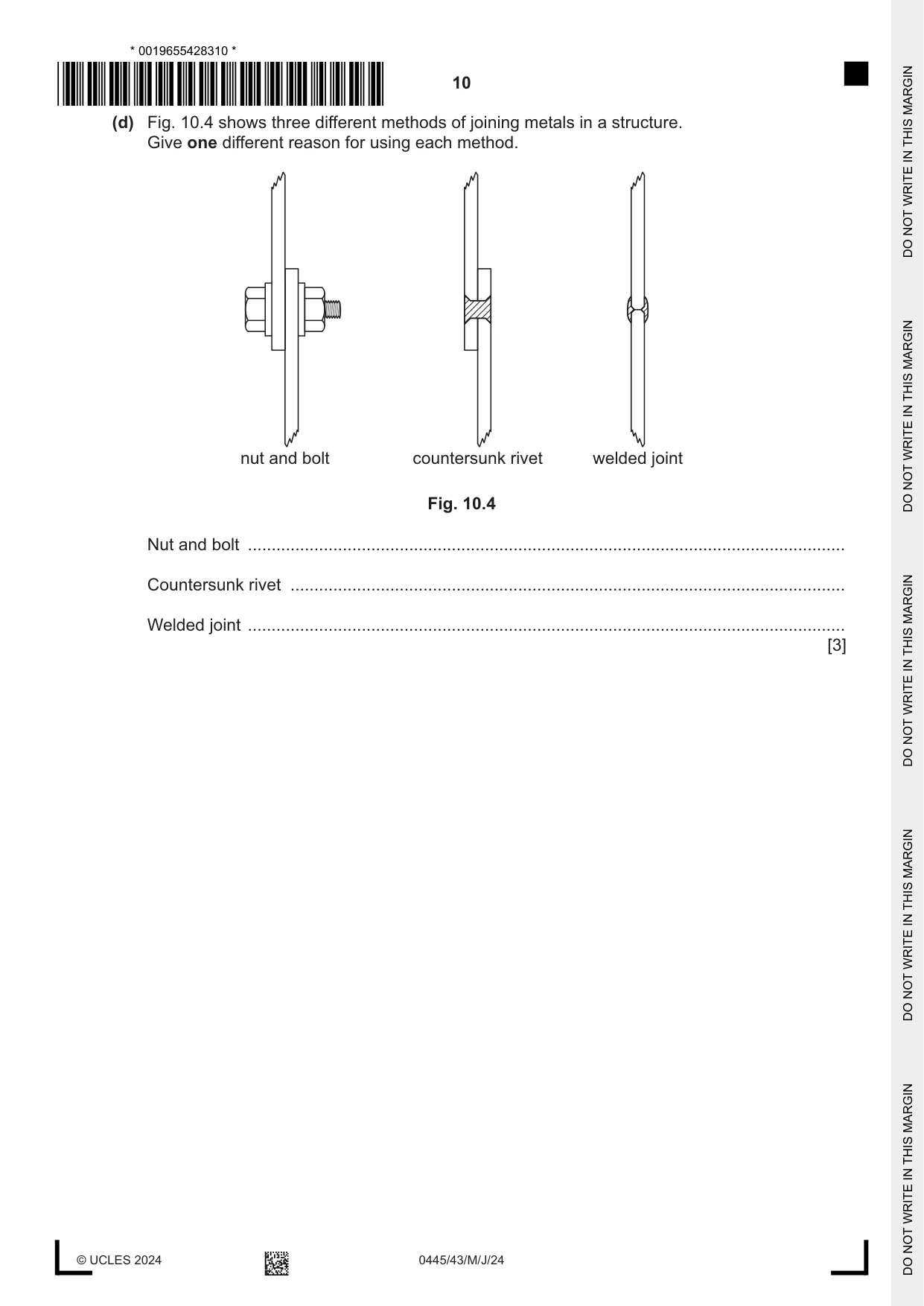
10 (a) Concrete is commonly used in structures. (i) Name three materials that are used to make concrete. 1 ........................................................................................................................................ 2 ........................................................................................................................................ 3 ........................................................................................................................................ [3] (ii) State the force that concrete will naturally have most resistance to. ..................................................................................................................................... [1] (iii) Use sketches and notes to show how resistance to other forces can be increased when using concrete. [2] (iv) Fig. 10.1 shows a design for a concrete pillar that could be used to resist load in a structure. 8.5 kN Ø 0.3 m Fig. 10.1 Calculate the stress that the pillar is subject to when a compressive force of 8.5 kN is applied. force (N) Use the formula: stress = cross-sectional area (m2) ........................................................................................................................................... ........................................................................................................................................... ........................................................................................................................................... ........................................................................................................................................... ..................................................................................................................................... [3] (b) Fig. 10.2 shows a beam in a roof with loads applied to it. The beam is supported at each end by a wall. 5.75 m 4.0 m 1.5 m 1200 N 2000 N R1 R2 Fig. 10.2 (i) The beam is in equilibrium. State what is meant by the term ‘equilibrium’. ........................................................................................................................................... ..................................................................................................................................... [1] (ii) Calculate the reactions at R1 and R2. Reaction at R1 ................................................................................................................... ........................................................................................................................................... ........................................................................................................................................... Reaction at R2 ................................................................................................................... ........................................................................................................................................... ........................................................................................................................................... [4] (iii) Give two examples of natural defects that could be present in a wooden beam. 1 ........................................................................................................................................ 2 ........................................................................................................................................ [2] (iv) Fig. 10.3 shows part of a roof truss. X timber section 100 × 60 Fig. 10.3 Use sketches and notes to show a suitable method of joining the timber at X. A method of preventing movement in the joint must be shown. [3] (c) Using an example of equipment used in building construction, explain two ‘Factor of Safety’ measures. ................................................................................................................................................... ................................................................................................................................................... ................................................................................................................................................... ............................................................................................................................................. [3] (d) Fig. 10.4 shows three different methods of joining metals in a structure. Give one different reason for using each method. nut and bolt countersunk rivet welded joint Fig. 10.4 Nut and bolt .............................................................................................................................. Countersunk rivet ..................................................................................................................... Welded joint .............................................................................................................................. [3]
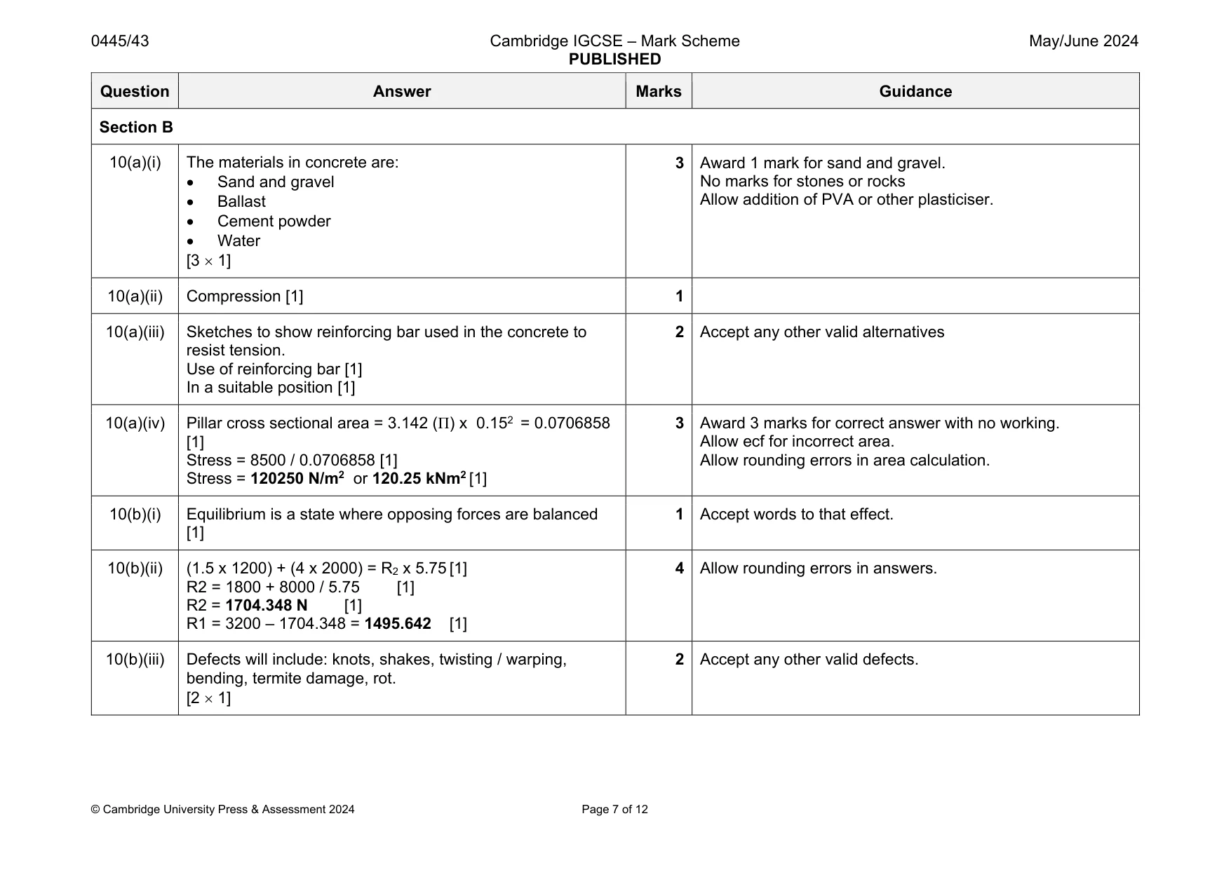
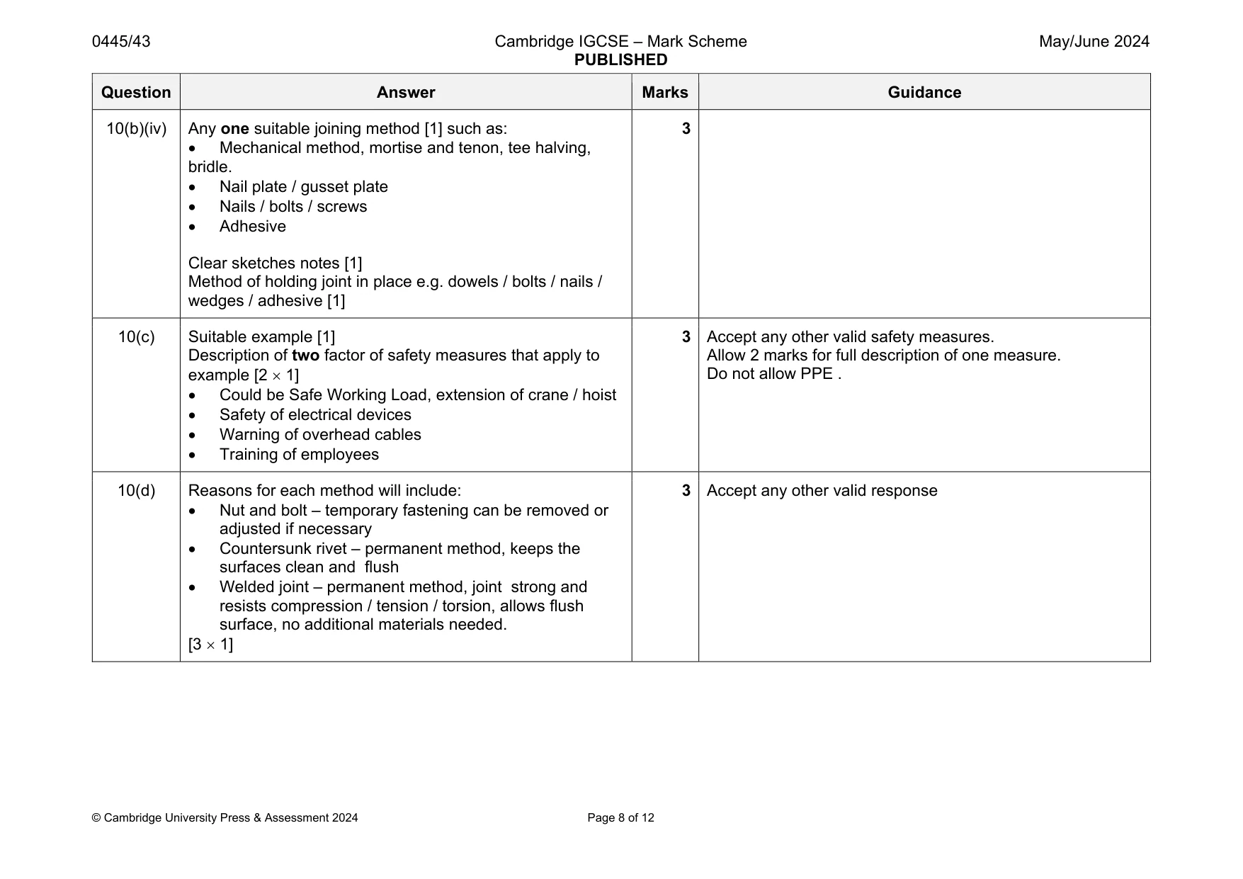
Mark scheme: 10(a)(i) The materials in concrete are: Sand and gravel Ballast Cement powder Water [3 1] 3 Award 1 mark for sand and gravel. No marks for stones or rocks Allow addition of PVA or other plasticiser. 10(a)(ii) Compression [1] 1 10(a)(iii) Sketches to show reinforcing bar used in the concrete to resist tension. Use of reinforcing bar [1] In a suitable position [1] 2 Accept any other valid alternatives 10(a)(iv) Pillar cross sectional area = 3.142 (Π) x 0.152 = 0.0706858 [1] Stress = 8500 / 0.0706858 [1] Stress = 120250 N/m2 or 120.25 kNm2 [1] 3 Award 3 marks for correct answer with no working. Allow ecf for incorrect area. Allow rounding errors in area calculation. 10(b)(i) Equilibrium is a state where opposing forces are balanced [1] 1 Accept words to that effect. 10(b)(ii) (1.5 x 1200) + (4 x 2000) = R2 x 5.75 [1] R2 = 1800 + 8000 / 5.75 [1] R2 = 1704.348 N [1] R1 = 3200 – 1704.348 = 1495.642 [1] 4 Allow rounding errors in answers. 10(b)(iii) Defects will include: knots, shakes, twisting / warping, bending, termite damage, rot. [2 1] 2 Accept any other valid defects. Question Answer Marks Guidance 10(b)(iv) Any one suitable joining method [1] such as: Mechanical method, mortise and tenon, tee halving, bridle. Nail plate / gusset plate Nails / bolts / screws Adhesive Clear sketches notes [1] Method of holding joint in place e.g. dowels / bolts / nails / wedges / adhesive [1] 3 10(c) Suitable example [1] Description of two factor of safety measures that apply to example [2 1] Could be Safe Working Load, extension of crane / hoist Safety of electrical devices Warning of overhead cables Training of employees 3 Accept any other valid safety measures. Allow 2 marks for full description of one measure. Do not allow PPE . 10(d) Reasons for each method will include: Nut and bolt – temporary fastening can be removed or adjusted if necessary Countersunk rivet – permanent method, keeps the surfaces clean and flush Welded joint – permanent method, joint strong and resists compression / tension / torsion, allows flush surface, no additional materials needed. [3 1] 3 Accept any other valid response
Q11 · A piece of exercise equipment in a park
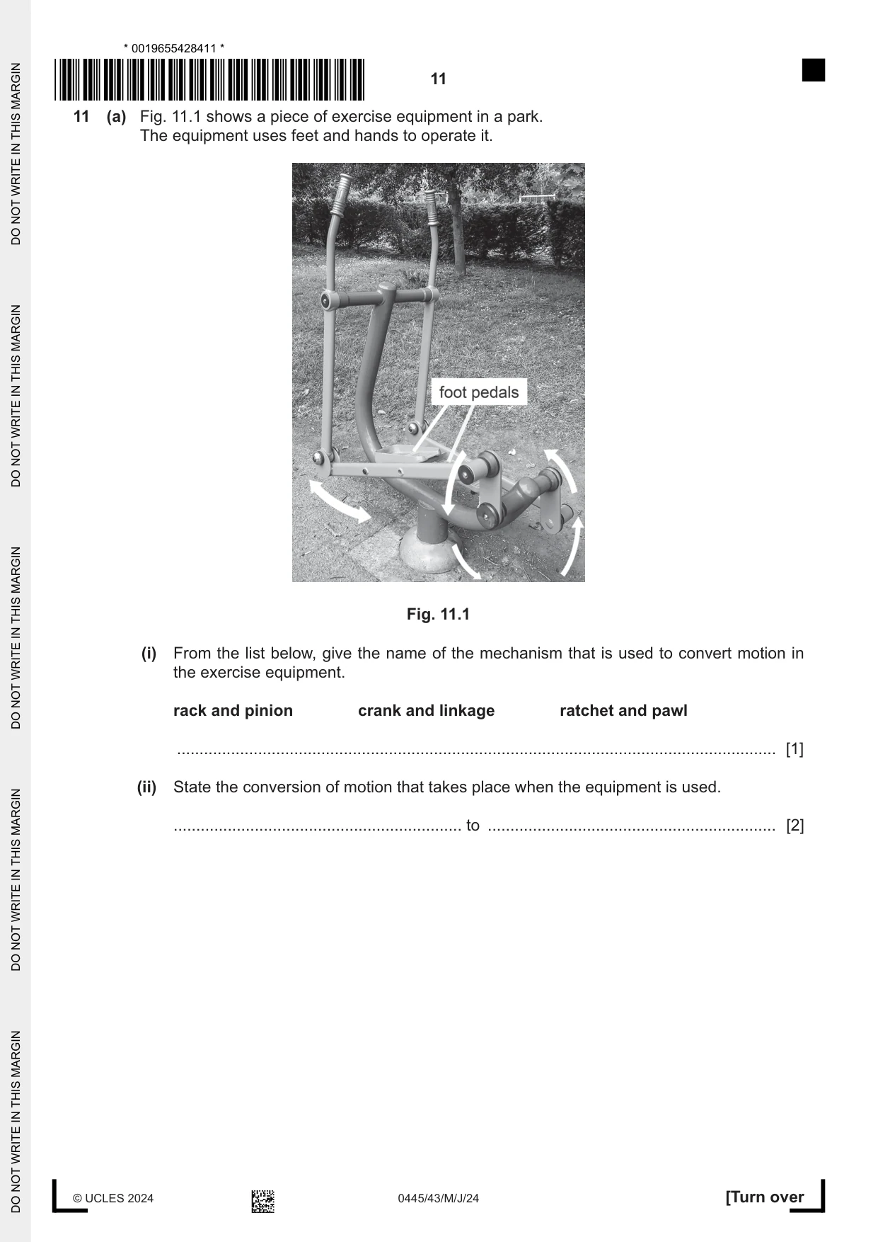
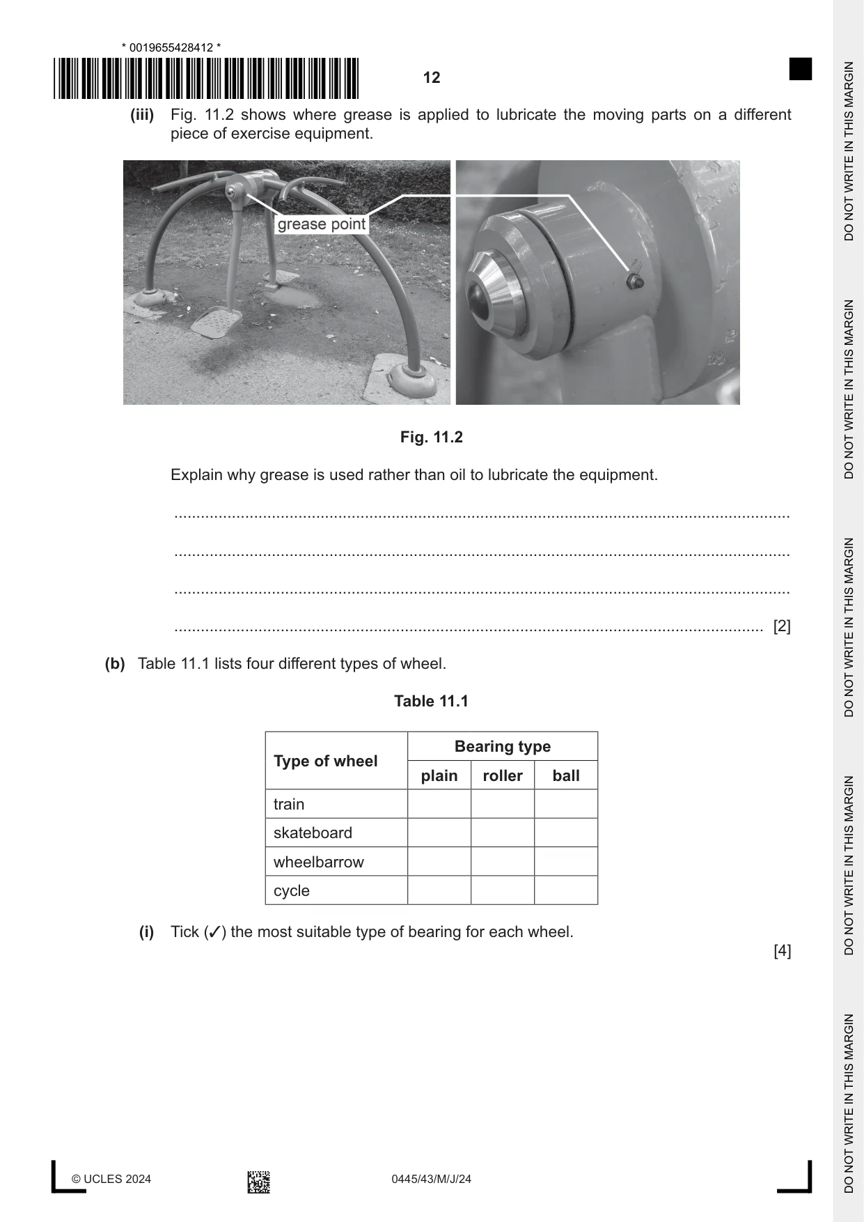
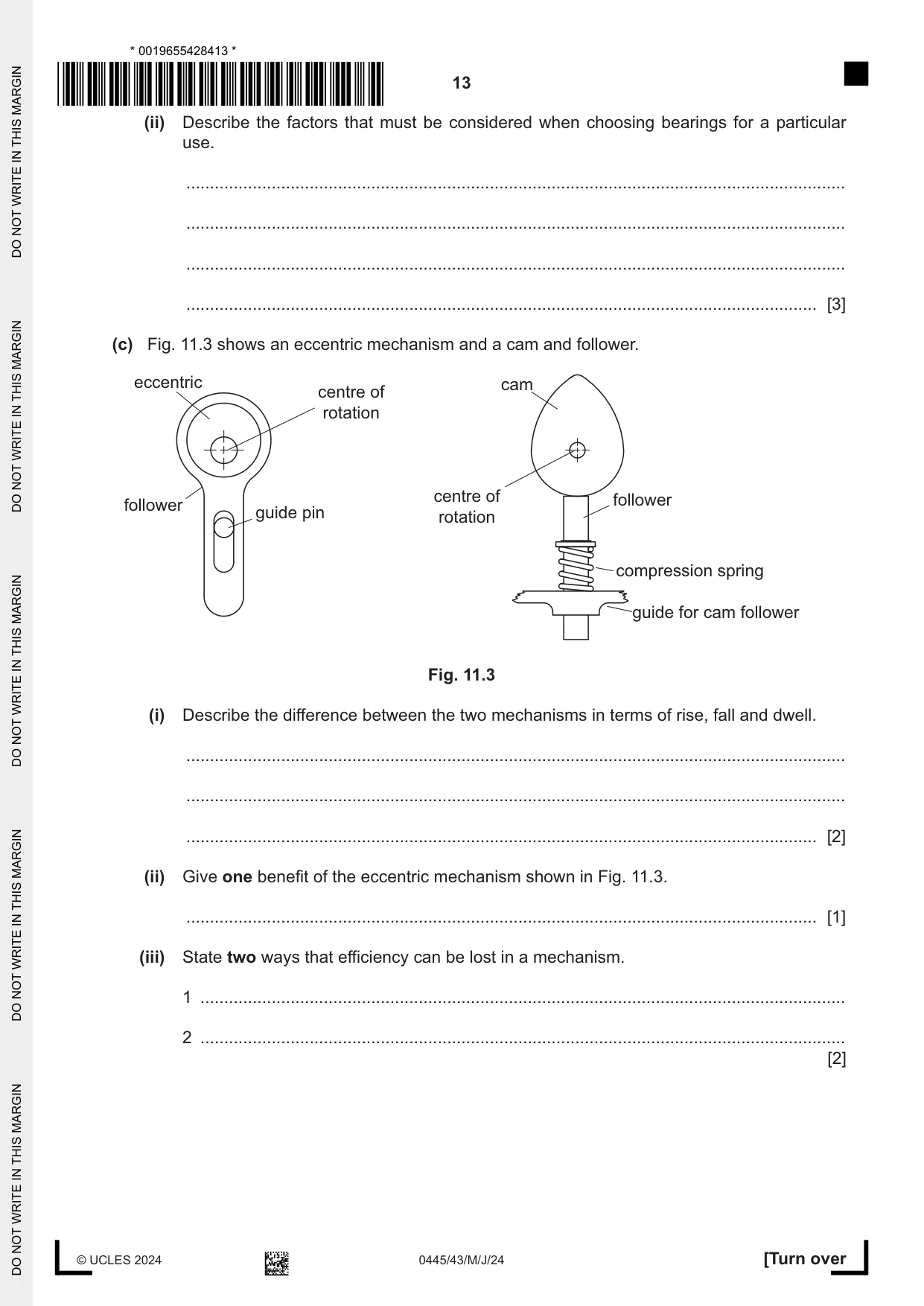
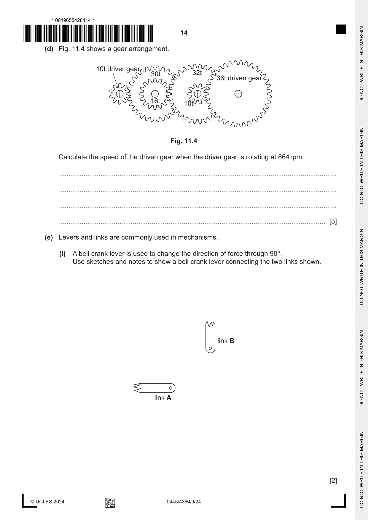
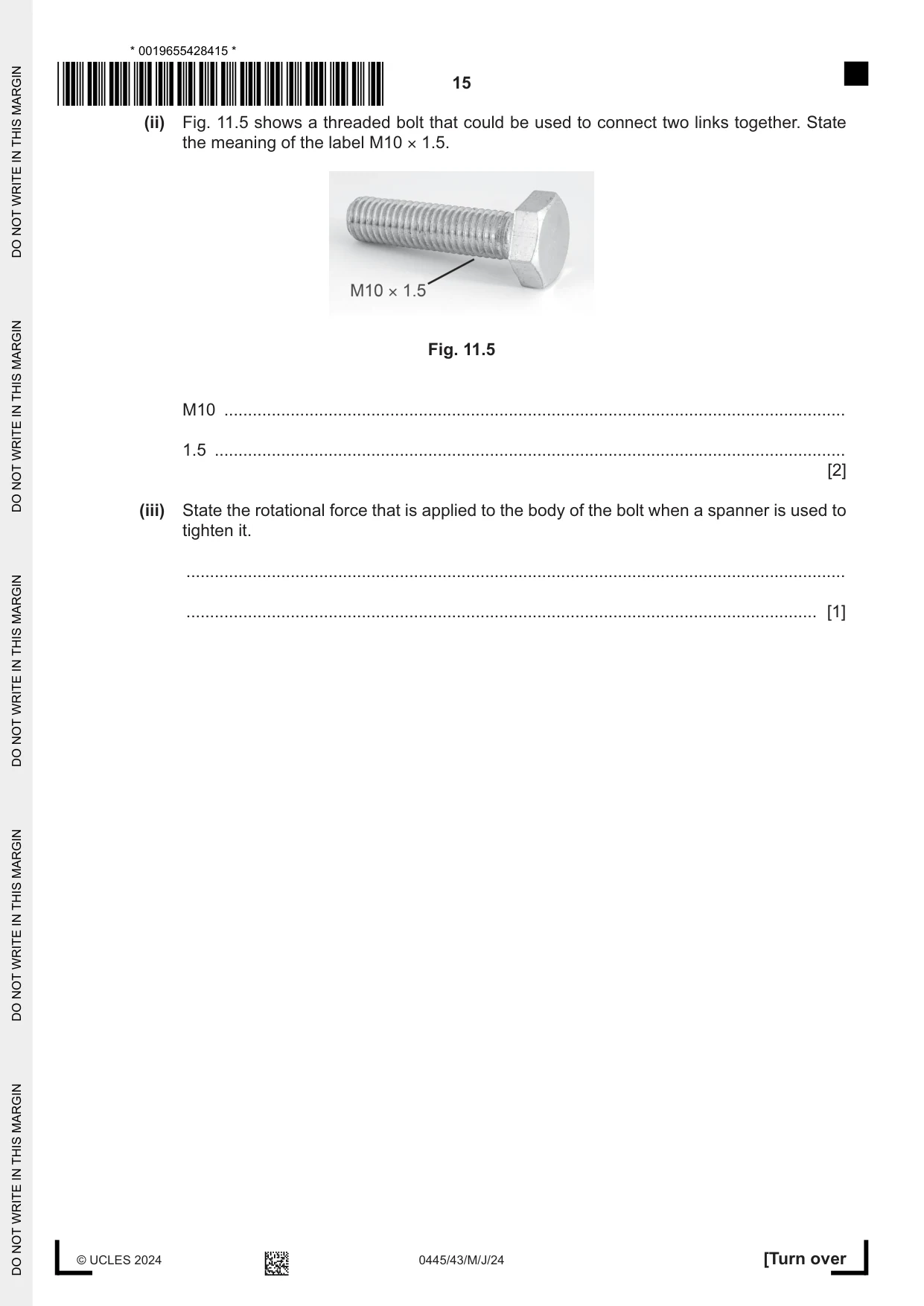
11 (a) Fig. 11.1 shows a piece of exercise equipment in a park. The equipment uses feet and hands to operate it. Fig. 11.1 (i) From the list below, give the name of the mechanism that is used to convert motion in the exercise equipment. rack and pinion crank and linkage ratchet and pawl ..................................................................................................................................... [1] (ii) State the conversion of motion that takes place when the equipment is used. ................................................................ to ................................................................ [2] (iii) Fig. 11.2 shows where grease is applied to lubricate the moving parts on a different piece of exercise equipment. Fig. 11.2 Explain why grease is used rather than oil to lubricate the equipment. ........................................................................................................................................... ........................................................................................................................................... ........................................................................................................................................... ..................................................................................................................................... [2] (b) Table 11.1 lists four different types of wheel. Table 11.1 Bearing type Type of wheel plain roller ball train skateboard wheelbarrow cycle (i) Tick (3) the most suitable type of bearing for each wheel. [4] (ii) Describe the factors that must be considered when choosing bearings for a particular use. ........................................................................................................................................... ........................................................................................................................................... ........................................................................................................................................... ..................................................................................................................................... [3] (c) Fig. 11.3 shows an eccentric mechanism and a cam and follower. eccentric cam centre of rotation centre of follower follower guide pin rotation compression spring guide for cam follower Fig. 11.3 (i) Describe the difference between the two mechanisms in terms of rise, fall and dwell. ........................................................................................................................................... ........................................................................................................................................... ..................................................................................................................................... [2] (ii) Give one benefit of the eccentric mechanism shown in Fig. 11.3. ..................................................................................................................................... [1] (iii) State two ways that efficiency can be lost in a mechanism. 1 ........................................................................................................................................ 2 ........................................................................................................................................ [2] (d) Fig. 11.4 shows a gear arrangement. 10t driver gear 30t 32t 36t driven gear 16t 10t Fig. 11.4 Calculate the speed of the driven gear when the driver gear is rotating at 864 rpm. ................................................................................................................................................... ................................................................................................................................................... ................................................................................................................................................... ............................................................................................................................................. [3] (e) Levers and links are commonly used in mechanisms. (i) A bell crank lever is used to change the direction of force through 90°. Use sketches and notes to show a bell crank lever connecting the two links shown. link B link A [2] (ii) Fig. 11.5 shows a threaded bolt that could be used to connect two links together. State the meaning of the label M10 × 1.5. Fig. 11.5 M10 ................................................................................................................................... 1.5 ..................................................................................................................................... [2] (iii) State the rotational force that is applied to the body of the bolt when a spanner is used to tighten it. ........................................................................................................................................... ..................................................................................................................................... [1]
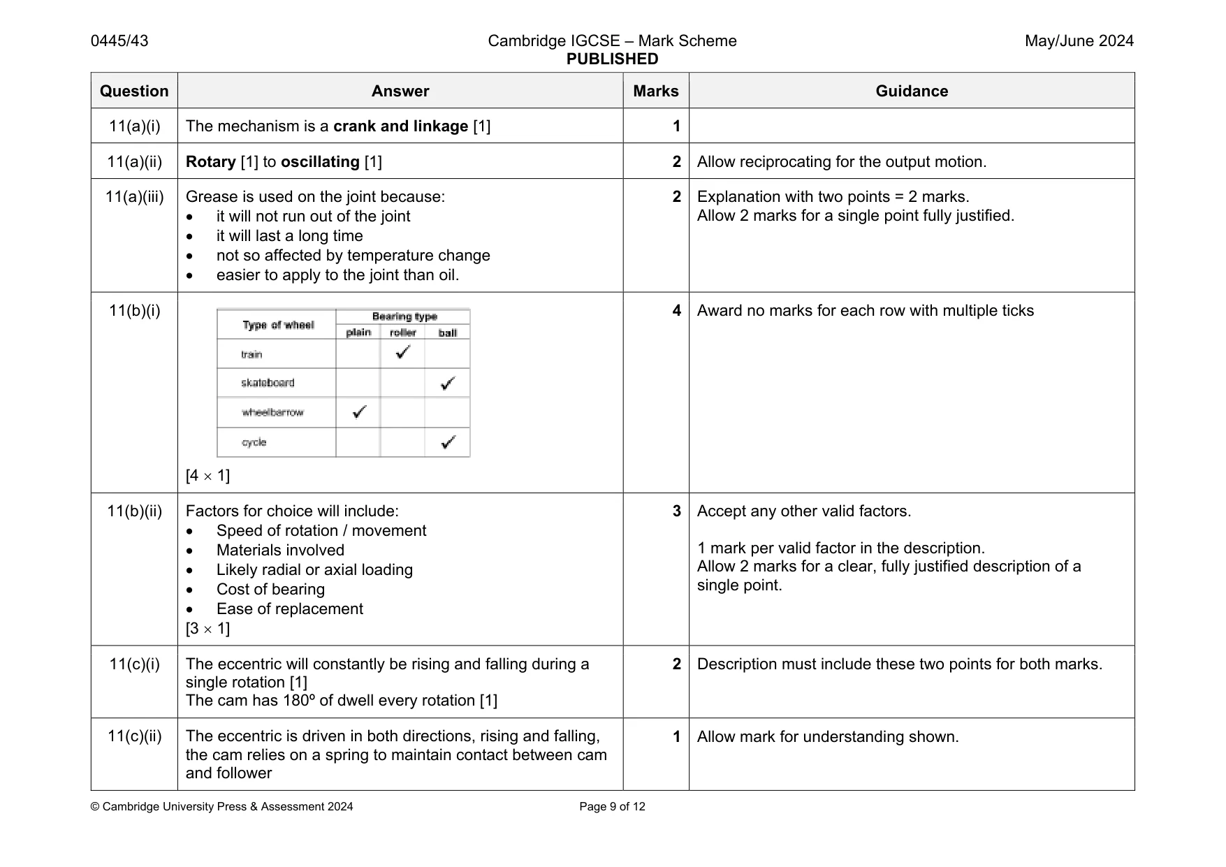
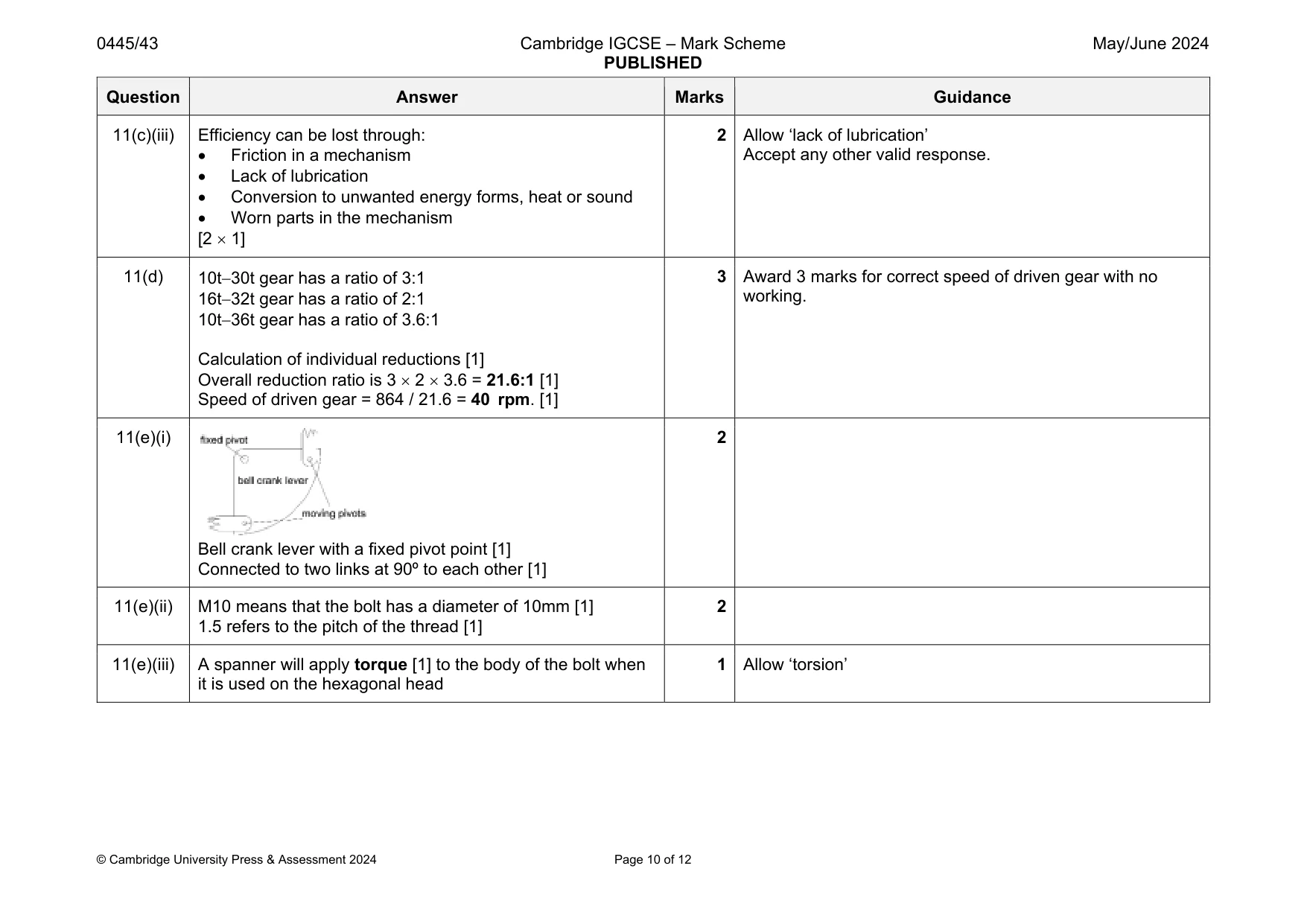
Mark scheme: 11(a)(i) The mechanism is a crank and linkage [1] 1 11(a)(ii) Rotary [1] to oscillating [1] 2 Allow reciprocating for the output motion. 11(a)(iii) Grease is used on the joint because: it will not run out of the joint it will last a long time not so affected by temperature change easier to apply to the joint than oil. 2 Explanation with two points = 2 marks. Allow 2 marks for a single point fully justified. 11(b)(i) [4 1] 4 Award no marks for each row with multiple ticks 11(b)(ii) Factors for choice will include: Speed of rotation / movement Materials involved Likely radial or axial loading Cost of bearing Ease of replacement [3 1] 3 Accept any other valid factors. 1 mark per valid factor in the description. Allow 2 marks for a clear, fully justified description of a single point. 11(c)(i) The eccentric will constantly be rising and falling during a single rotation [1] The cam has 180º of dwell every rotation [1] 2 Description must include these two points for both marks. 11(c)(ii) The eccentric is driven in both directions, rising and falling, the cam relies on a spring to maintain contact between cam and follower 1 Allow mark for understanding shown. Question Answer Marks Guidance 11(c)(iii) Efficiency can be lost through: Friction in a mechanism Lack of lubrication Conversion to unwanted energy forms, heat or sound Worn parts in the mechanism [2 1] 2 Allow ‘lack of lubrication’ Accept any other valid response. 11(d) 10t30t gear has a ratio of 3:1 16t32t gear has a ratio of 2:1 10t36t gear has a ratio of 3.6:1 Calculation of individual reductions [1] Overall reduction ratio is 3 2 3.6 = 21.6:1 [1] Speed of driven gear = 864 / 21.6 = 40 rpm. [1] 3 Award 3 marks for correct speed of driven gear with no working. 11(e)(i) Bell crank lever with a fixed pivot point [1] Connected to two links at 90º to each other [1] 2 11(e)(ii) M10 means that the bolt has a diameter of 10mm [1] 1.5 refers to the pitch of the thread [1] 2 11(e)(iii) A spanner will apply torque [1] to the body of the bolt when it is used on the hexagonal head 1 Allow ‘torsion’
Q12 · A rectangular LED that will be used to show the logic level of a NAND gate output
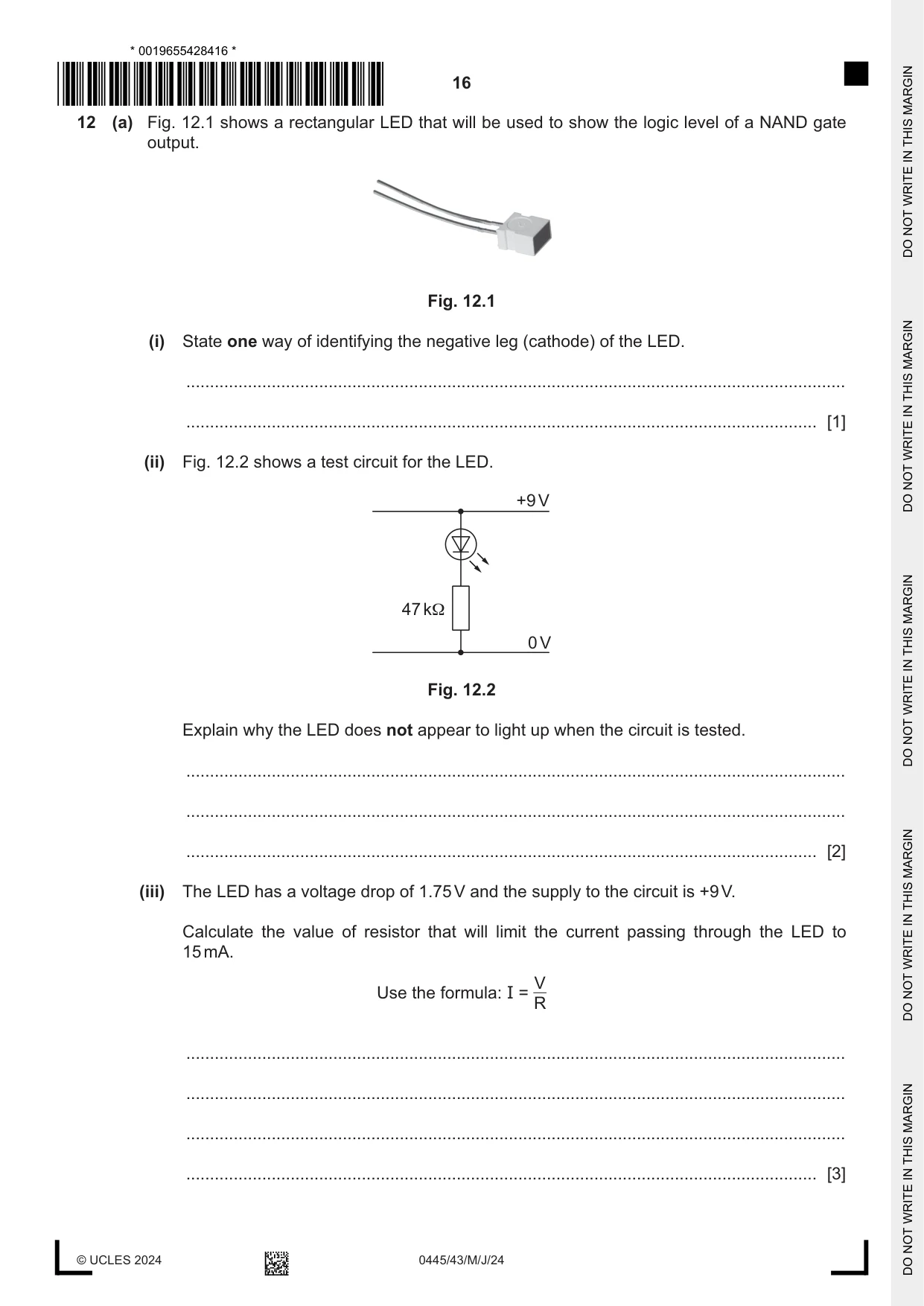
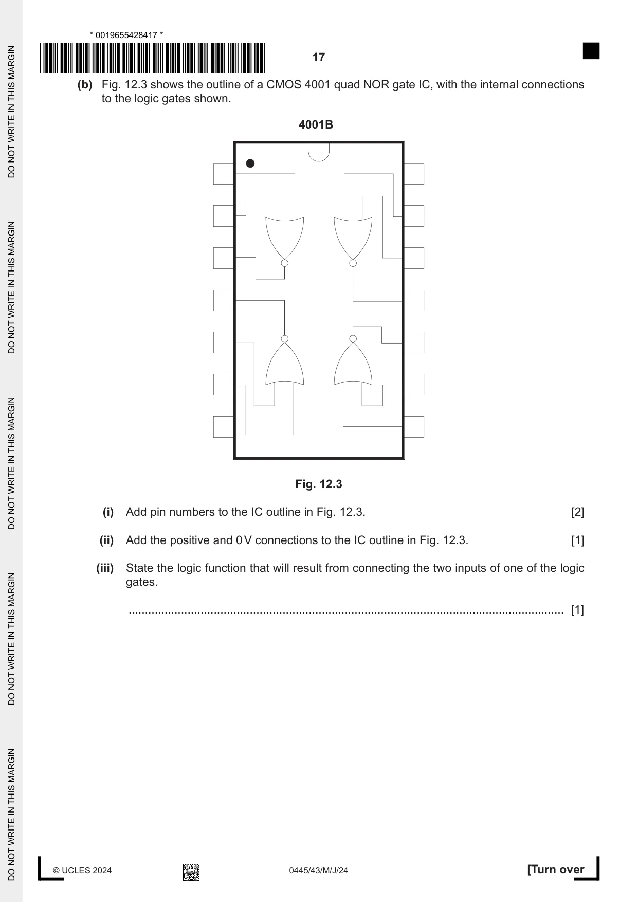
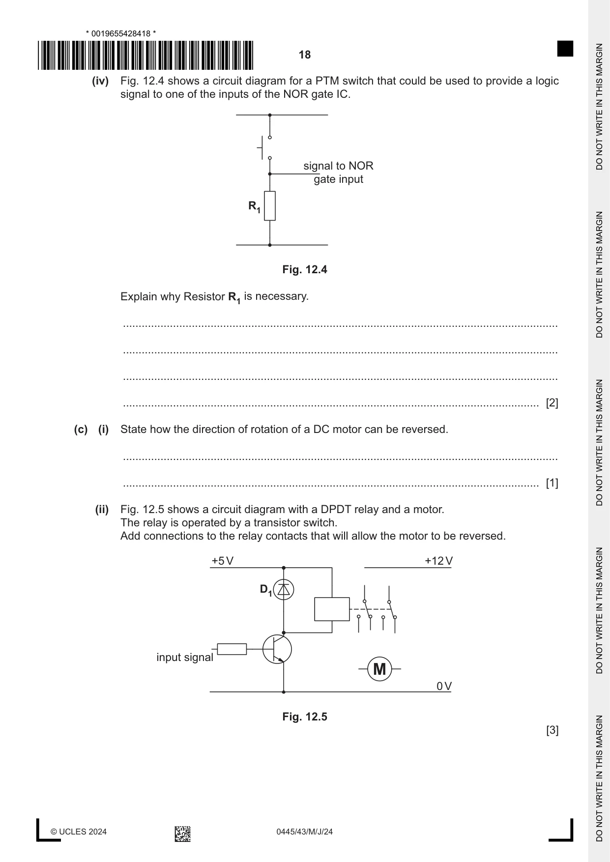
12 (a) Fig. 12.1 shows a rectangular LED that will be used to show the logic level of a NAND gate output. Fig. 12.1 (i) State one way of identifying the negative leg (cathode) of the LED. ........................................................................................................................................... ..................................................................................................................................... [1] (ii) Fig. 12.2 shows a test circuit for the LED. +9 V 47 kΩ 0 V Fig. 12.2 Explain why the LED does not appear to light up when the circuit is tested. ........................................................................................................................................... ........................................................................................................................................... ..................................................................................................................................... [2] (iii) The LED has a voltage drop of 1.75 V and the supply to the circuit is +9 V. Calculate the value of resistor that will limit the current passing through the LED to 15 mA. V Use the formula: I = R ........................................................................................................................................... ........................................................................................................................................... ........................................................................................................................................... ..................................................................................................................................... [3] (b) Fig. 12.3 shows the outline of a CMOS 4001 quad NOR gate IC, with the internal connections to the logic gates shown. 4001B Fig. 12.3 (i) Add pin numbers to the IC outline in Fig. 12.3. [2] (ii) Add the positive and 0 V connections to the IC outline in Fig. 12.3. [1] (iii) State the logic function that will result from connecting the two inputs of one of the logic gates. ..................................................................................................................................... [1] (iv) Fig. 12.4 shows a circuit diagram for a PTM switch that could be used to provide a logic signal to one of the inputs of the NOR gate IC. signal to NOR gate input R1 Fig. 12.4 Explain why Resistor R1 is necessary. ........................................................................................................................................... ........................................................................................................................................... ........................................................................................................................................... ..................................................................................................................................... [2] (c) (i) State how the direction of rotation of a DC motor can be reversed. ........................................................................................................................................... ..................................................................................................................................... [1] (ii) Fig. 12.5 shows a circuit diagram with a DPDT relay and a motor. The relay is operated by a transistor switch. Add connections to the relay contacts that will allow the motor to be reversed. +5 V +12 V D1 input signal M 0 V Fig. 12.5 [3]
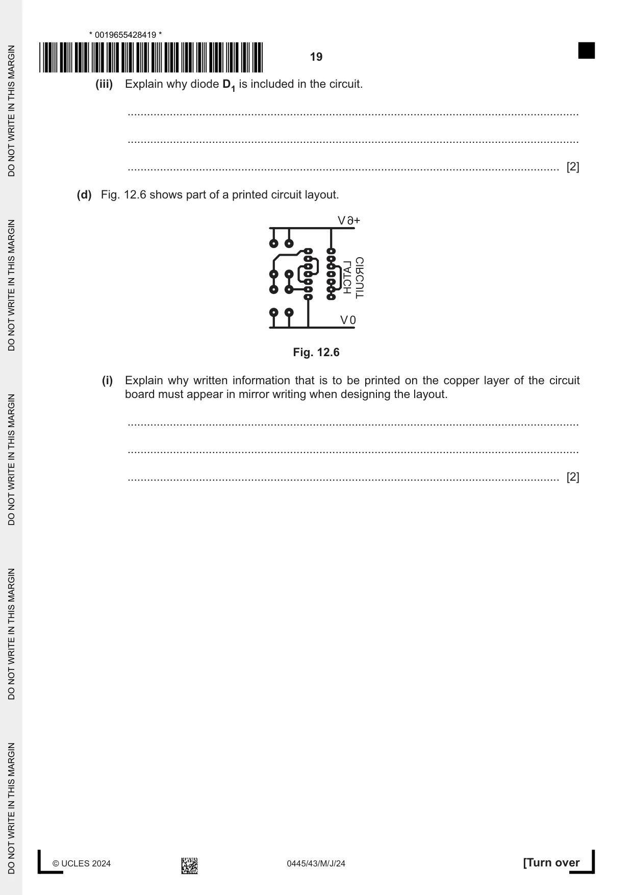
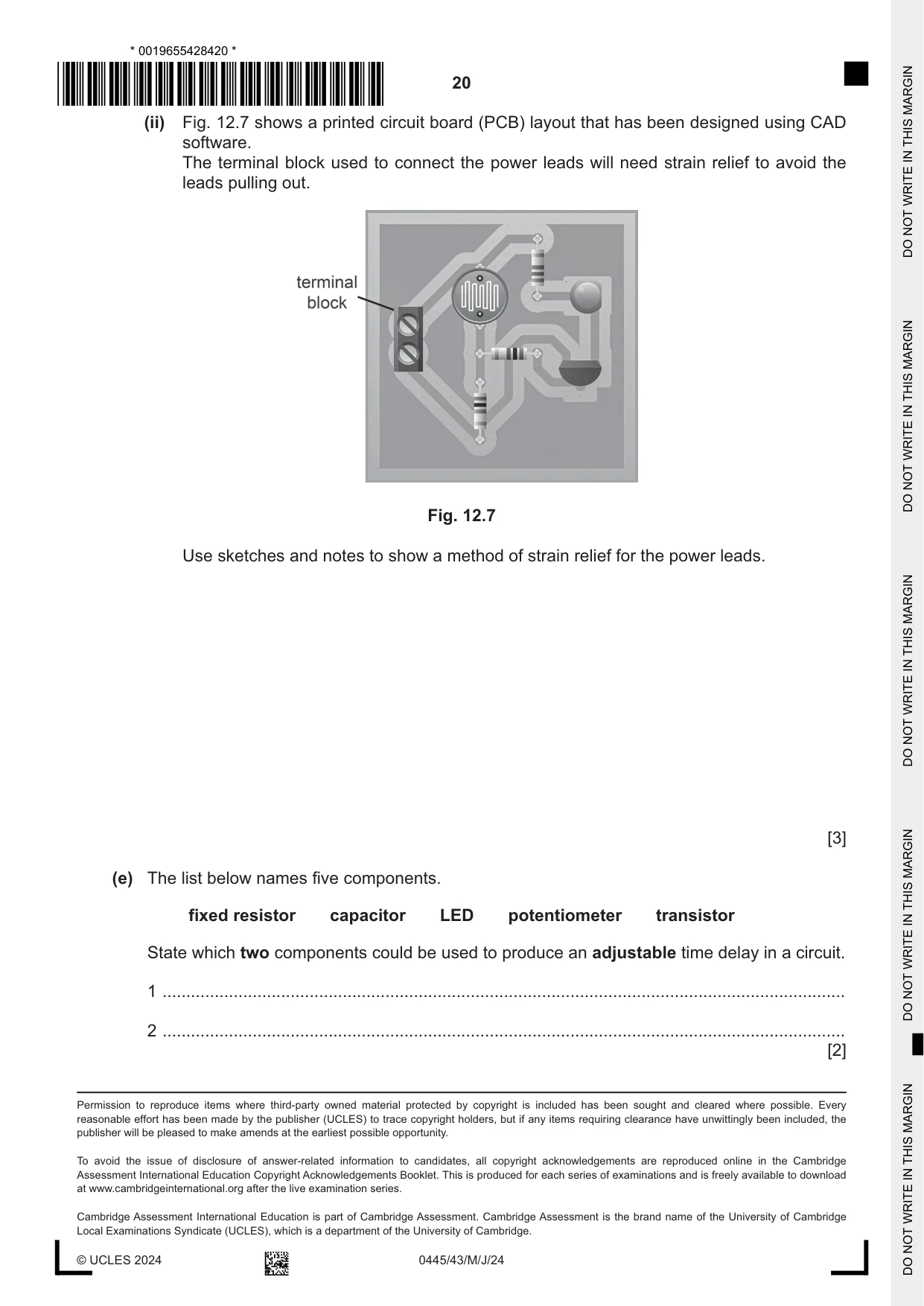
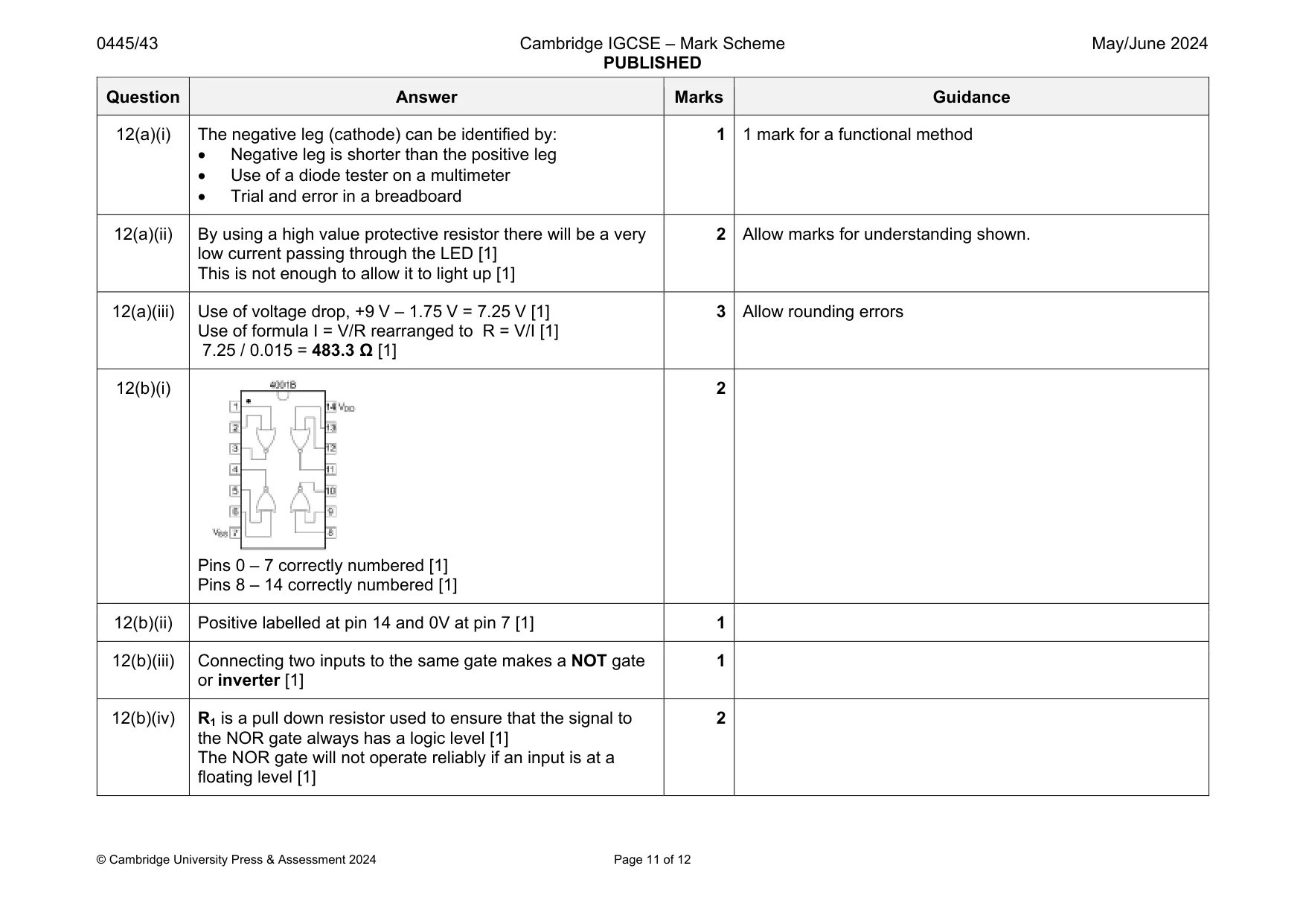
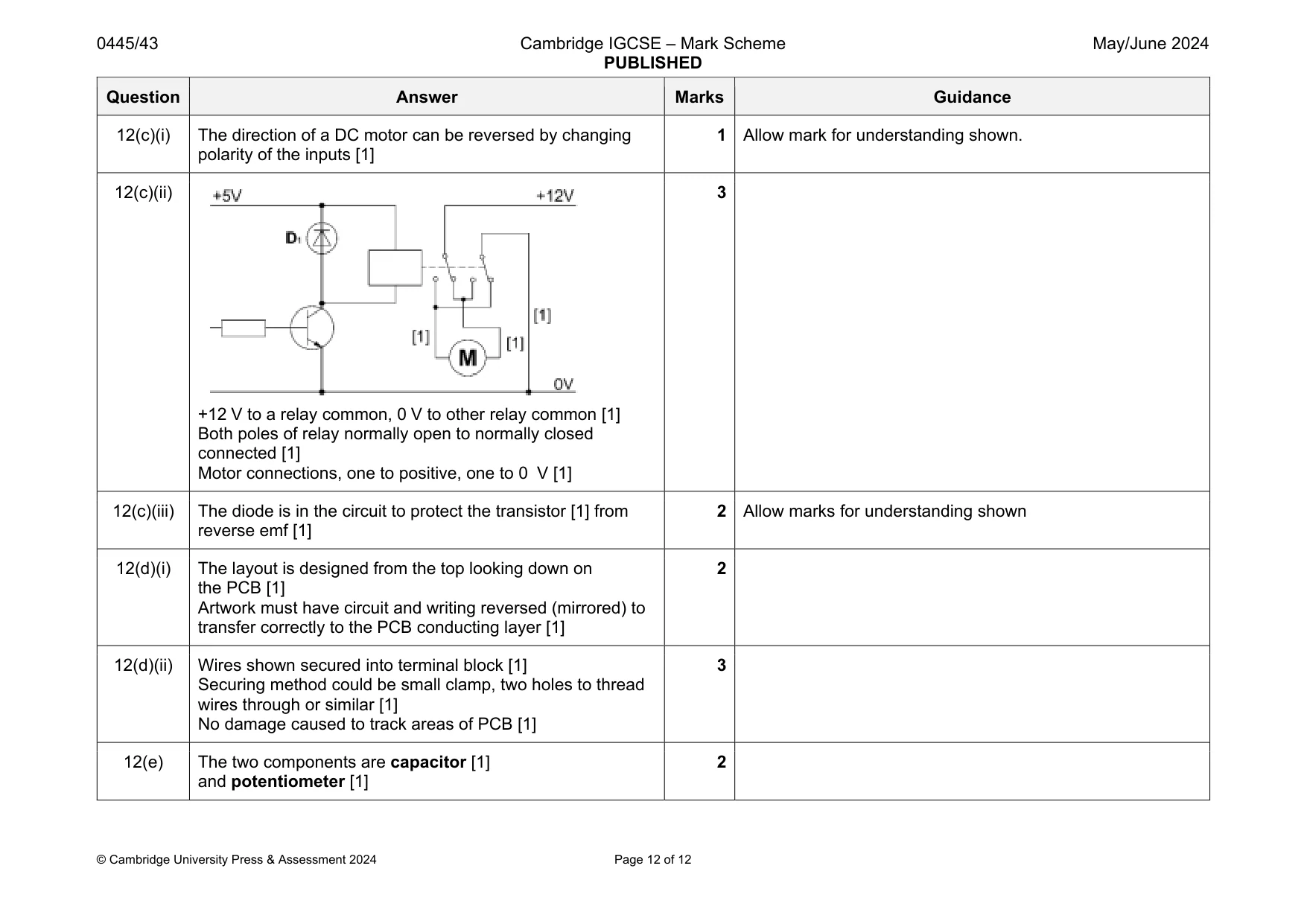
Mark scheme: 12(a)(i) The negative leg (cathode) can be identified by: Negative leg is shorter than the positive leg Use of a diode tester on a multimeter Trial and error in a breadboard 1 1 mark for a functional method 12(a)(ii) By using a high value protective resistor there will be a very low current passing through the LED [1] This is not enough to allow it to light up [1] 2 Allow marks for understanding shown. 12(a)(iii) Use of voltage drop, +9 V – 1.75 V = 7.25 V [1] Use of formula I = V/R rearranged to R = V/I [1] 7.25 / 0.015 = 483.3 Ω [1] 3 Allow rounding errors 12(b)(i) Pins 0 – 7 correctly numbered [1] Pins 8 – 14 correctly numbered [1] 2 12(b)(ii) Positive labelled at pin 14 and 0V at pin 7 [1] 1 12(b)(iii) Connecting two inputs to the same gate makes a NOT gate or inverter [1] 1 12(b)(iv) R1 is a pull down resistor used to ensure that the signal to the NOR gate always has a logic level [1] The NOR gate will not operate reliably if an input is at a floating level [1] 2 Question Answer Marks Guidance 12(c)(i) The direction of a DC motor can be reversed by changing polarity of the inputs [1] 1 Allow mark for understanding shown. 12(c)(ii) +12 V to a relay common, 0 V to other relay common [1] Both poles of relay normally open to normally closed connected [1] Motor connections, one to positive, one to 0 V [1] 3 12(c)(iii) The diode is in the circuit to protect the transistor [1] from reverse emf [1] 2 Allow marks for understanding shown 12(d)(i) The layout is designed from the top looking down on the PCB [1] Artwork must have circuit and writing reversed (mirrored) to transfer correctly to the PCB conducting layer [1] 2 12(d)(ii) Wires shown secured into terminal block [1] Securing method could be small clamp, two holes to thread wires through or similar [1] No damage caused to track areas of PCB [1] 3 12(e) The two components are capacitor [1] and potentiometer [1] 2
What was in this paper
The subtopics covered by these 12 questions, and how many questions each got. Open one in a new tab to see every Cambridge question on it.
What you needed in this session
Cambridge’s own grade thresholds for 2024 May/June, Paper 4 · Variant 3. A higher threshold means an easier paper — the bar moves with how the cohort did.