Cambridge IGCSE Design and Technology 0445 — 2022 May/June Paper 4 · Variant 3
0445/43/M/J/22 · 12 questions · 50 marks · ≈56 min
The question paper and its mark scheme, free to read here and free to download. This is Cambridge’s own paper, exactly as it was sat.
Question paper16 pages

Mark scheme14 pages
Answers below. Sit the paper first if you are practising.
Questions as text
Q1 · Name three types of man-made structure
1 Name three types of man-made structure. 1 ....................................................................................................................................................... 2 ....................................................................................................................................................... 3 ....................................................................................................................................................... [3]
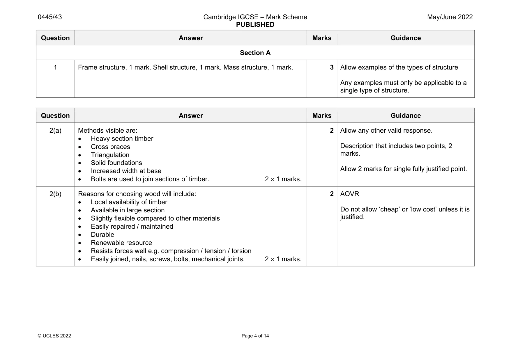
Mark scheme: 1 Frame structure, 1 mark. Shell structure, 1 mark. Mass structure, 1 mark. 3 Allow examples of the types of structure Any examples must only be applicable to a single type of structure.
Q2 · A wooden support structure for a section of railway track
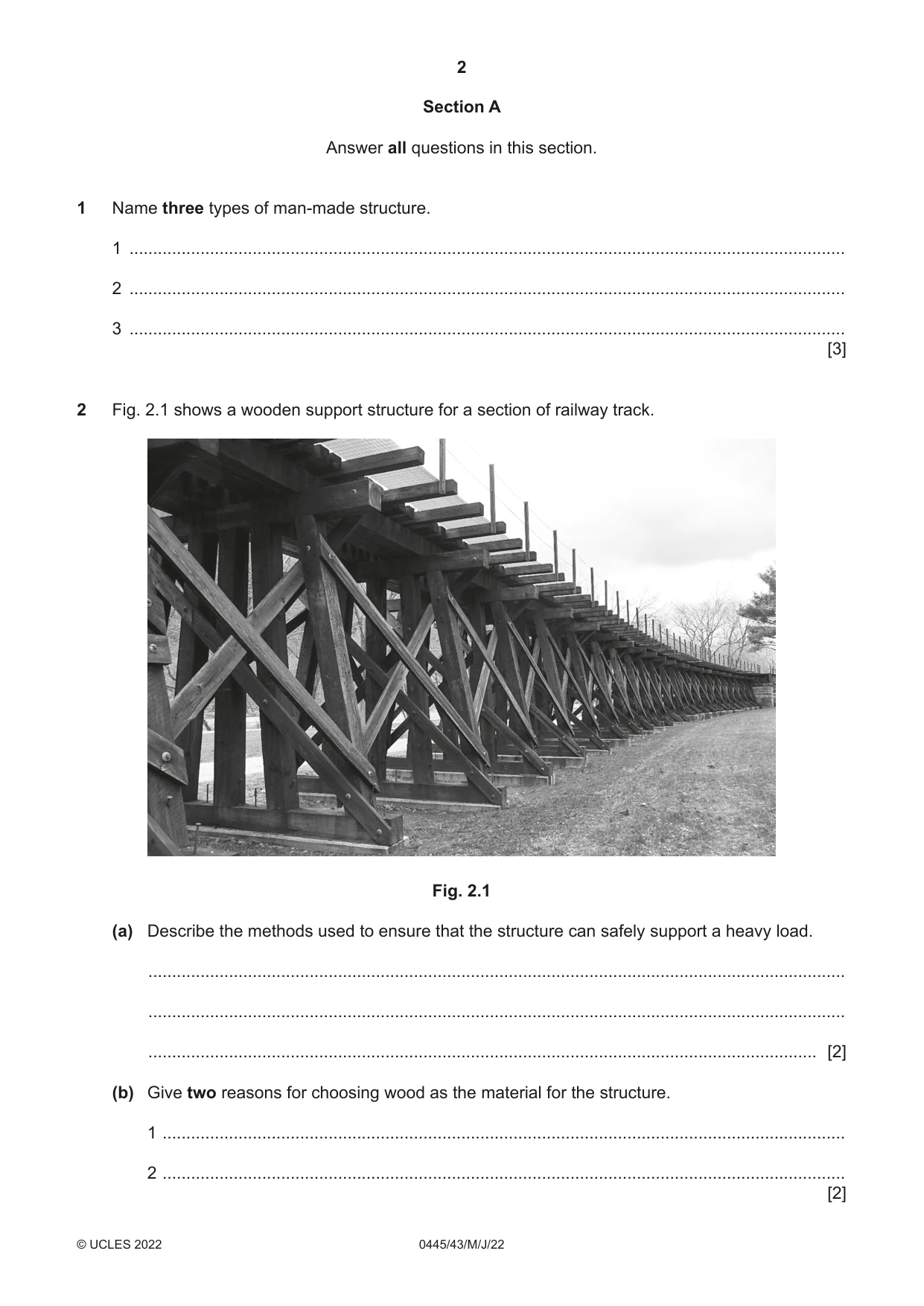
2 Fig. 2.1 shows a wooden support structure for a section of railway track. Fig. 2.1 (a) Describe the methods used to ensure that the structure can safely support a heavy load. ................................................................................................................................................... ................................................................................................................................................... ............................................................................................................................................. [2] (b) Give two reasons for choosing wood as the material for the structure. 1 ................................................................................................................................................ 2 ................................................................................................................................................ [2]
Mark scheme: 2(a) Methods visible are: Heavy section timber Cross braces Triangulation Solid foundations Increased width at base Bolts are used to join sections of timber. 2 1 marks. 2 Allow any other valid response. Description that includes two points, 2 marks. Allow 2 marks for single fully justified point. 2(b) Reasons for choosing wood will include: Local availability of timber Available in large section Slightly flexible compared to other materials Easily repaired / maintained Durable Renewable resource Resists forces well e.g. compression / tension / torsion Easily joined, nails, screws, bolts, mechanical joints. 2 1 marks. 2 AOVR Do not allow ‘cheap’ or ‘low cost’ unless it is justified.
Q3 · Window frames can be made from wood or plastic
3 Window frames can be made from wood or plastic. (a) Give two advantages of using plastic rather than wood for window frames. 1 ................................................................................................................................................ ................................................................................................................................................... 2 ................................................................................................................................................ ................................................................................................................................................... [2] (b) Give two disadvantages of using plastic rather than wood for window frames. 1 ................................................................................................................................................ ................................................................................................................................................... 2 ................................................................................................................................................ ................................................................................................................................................... [2]
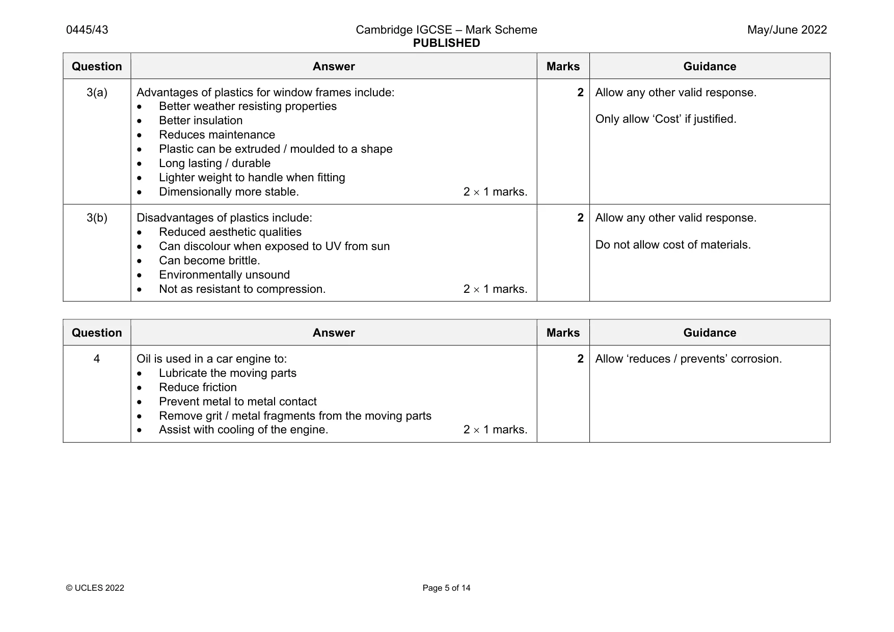
Mark scheme: 3(a) Advantages of plastics for window frames include: Better weather resisting properties Better insulation Reduces maintenance Plastic can be extruded / moulded to a shape Long lasting / durable Lighter weight to handle when fitting Dimensionally more stable. 2 1 marks. 2 Allow any other valid response. Only allow ‘Cost’ if justified. 3(b) Disadvantages of plastics include: Reduced aesthetic qualities Can discolour when exposed to UV from sun Can become brittle. Environmentally unsound Not as resistant to compression. 2 1 marks. 2 Allow any other valid response. Do not allow cost of materials.
Q4 · State two purposes of oil in a car engine
4 State two purposes of oil in a car engine. 1 ....................................................................................................................................................... 2 ....................................................................................................................................................... [2]
Mark scheme: 4 Oil is used in a car engine to: Lubricate the moving parts Reduce friction Prevent metal to metal contact Remove grit / metal fragments from the moving parts Assist with cooling of the engine. 2 1 marks.
Q5 · Two examples of conversion of motion
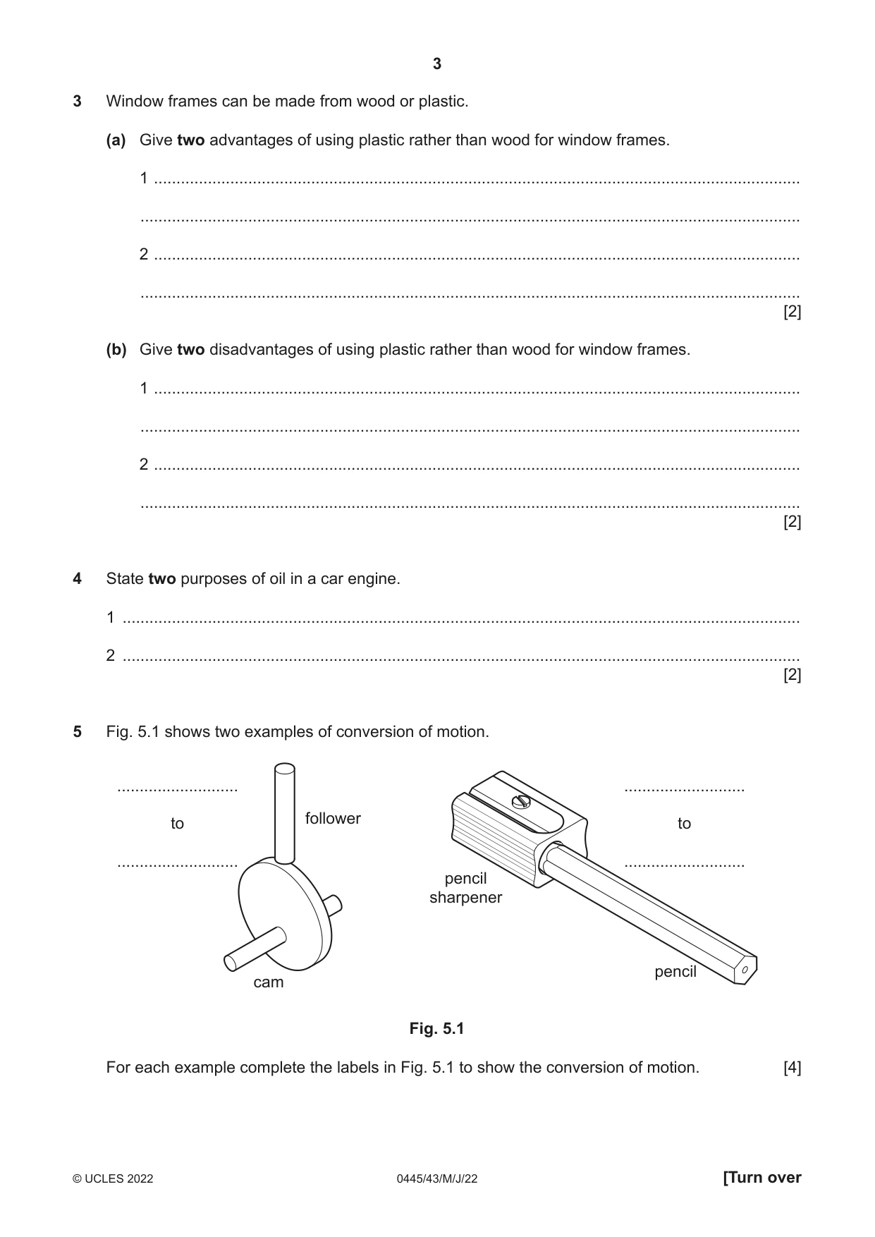
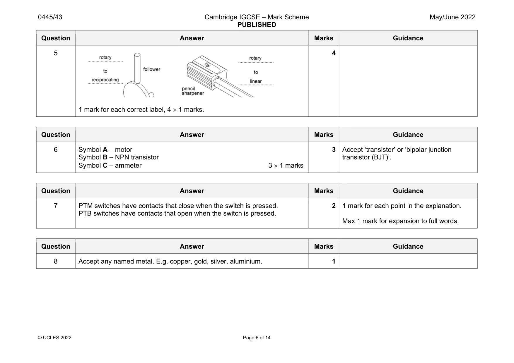
5 Fig. 5.1 shows two examples of conversion of motion. ........................... ........................... follower to to ........................... ........................... pencil sharpener pencil cam Fig. 5.1 For each example complete the labels in Fig. 5.1 to show the conversion of motion. [4]
Mark scheme: 5 1 mark for each correct label, 4 1 marks. 4
Question 6
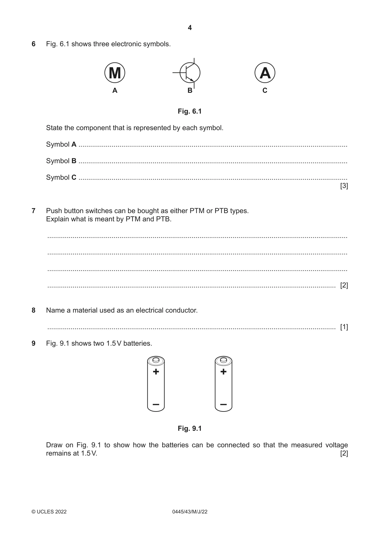
6 Fig. 6.1 shows three electronic symbols. M A A B C Fig. 6.1 State the component that is represented by each symbol. Symbol A .......................................................................................................................................... Symbol B .......................................................................................................................................... Symbol C .......................................................................................................................................... [3]
Mark scheme: 6 Symbol A – motor Symbol B – NPN transistor Symbol C – ammeter 3 1 marks 3 Accept ‘transistor’ or ‘bipolar junction transistor (BJT)’.
Q7 · Push button switches can be bought as either PTM or PTB types
7 Push button switches can be bought as either PTM or PTB types. Explain what is meant by PTM and PTB. .......................................................................................................................................................... .......................................................................................................................................................... .......................................................................................................................................................... .................................................................................................................................................... [2]
Mark scheme: 7 PTM switches have contacts that close when the switch is pressed. PTB switches have contacts that open when the switch is pressed. 2 1 mark for each point in the explanation. Max 1 mark for expansion to full words.
Q8 · Name a material used as an electrical conductor
8 Name a material used as an electrical conductor. .................................................................................................................................................... [1]
Mark scheme: 8 Accept any named metal. E.g. copper, gold, silver, aluminium. 1
Q9 · Two 1.5 V batteries
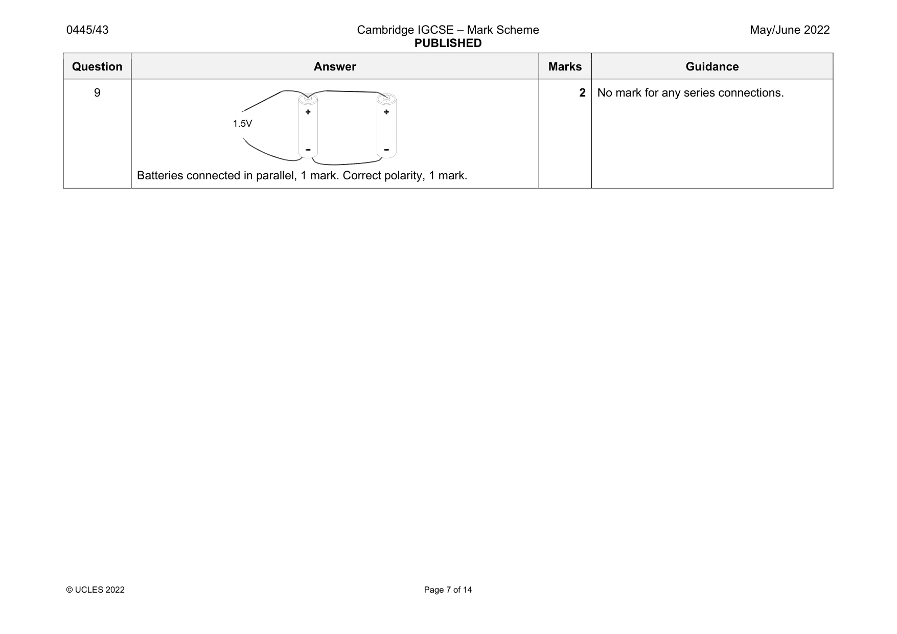
9 Fig. 9.1 shows two 1.5 V batteries. + + – – Fig. 9.1 Draw on Fig. 9.1 to show how the batteries can be connected so that the measured voltage remains at 1.5 V. [2]
Mark scheme: 9 Batteries connected in parallel, 1 mark. Correct polarity, 1 mark. 2 No mark for any series connections. 1.5V
Q10 · Views of a wooden aircraft propeller made from a number of layers of hardwood glued…
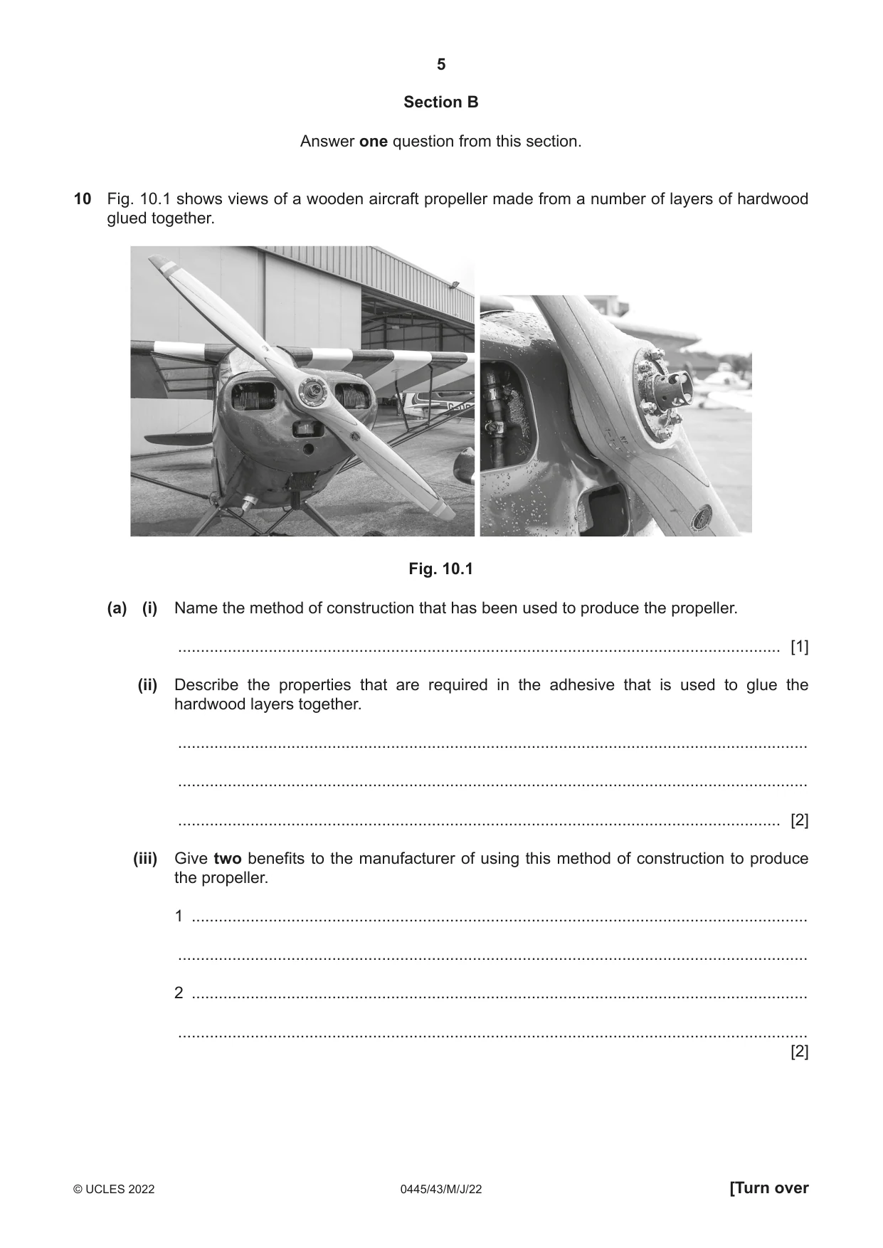
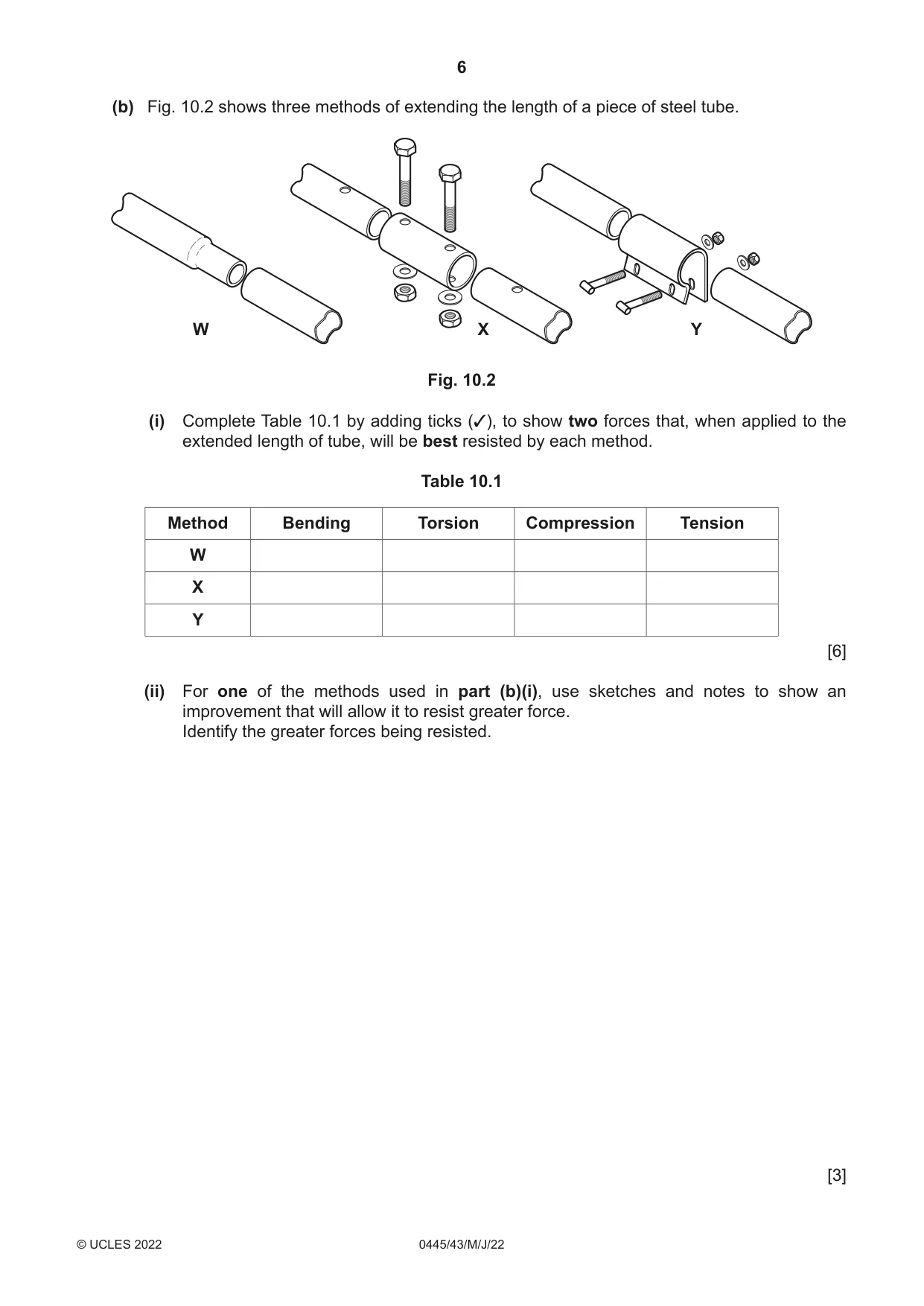
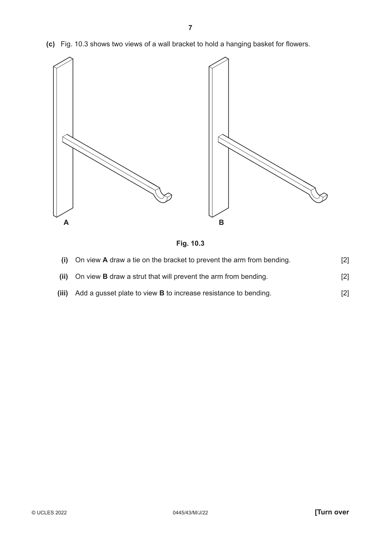
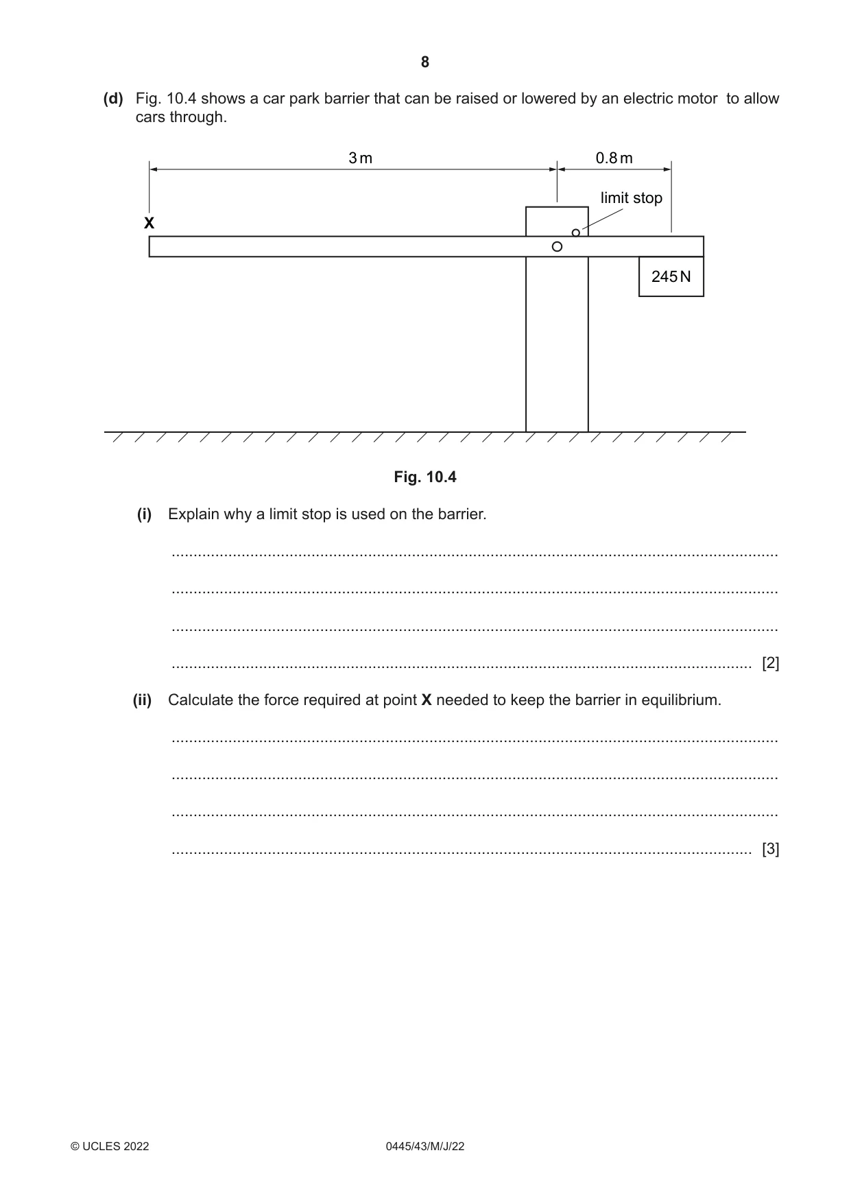
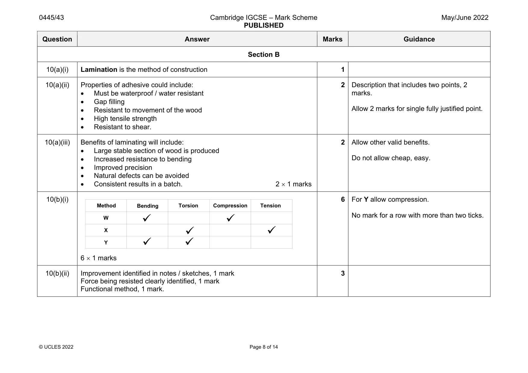
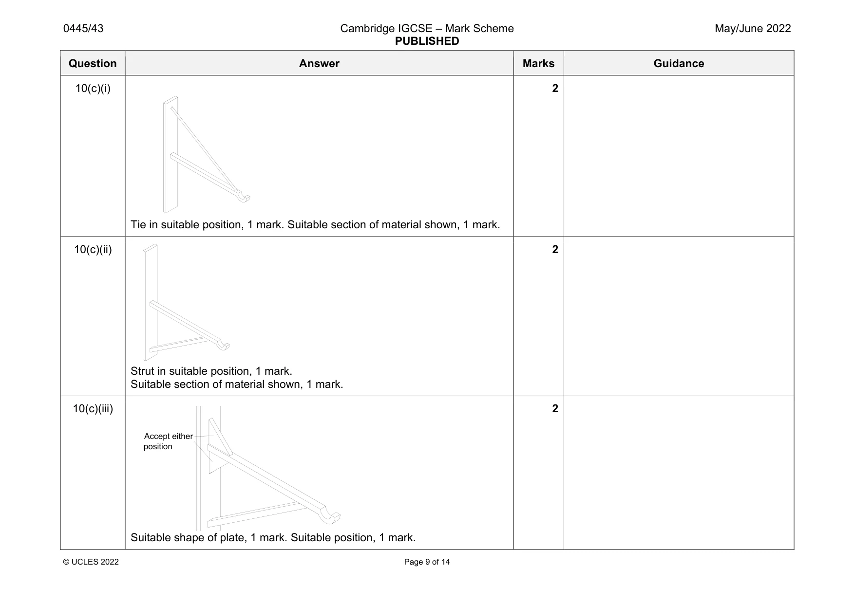
10 Fig. 10.1 shows views of a wooden aircraft propeller made from a number of layers of hardwood glued together. Fig. 10.1 (a) (i) Name the method of construction that has been used to produce the propeller. ..................................................................................................................................... [1] (ii) Describe the properties that are required in the adhesive that is used to glue the hardwood layers together. ........................................................................................................................................... ........................................................................................................................................... ..................................................................................................................................... [2] (iii) Give two benefits to the manufacturer of using this method of construction to produce the propeller. 1 ........................................................................................................................................ ........................................................................................................................................... 2 ........................................................................................................................................ ........................................................................................................................................... [2] (b) Fig. 10.2 shows three methods of extending the length of a piece of steel tube. W X Y Fig. 10.2 (i) Complete Table 10.1 by adding ticks (3), to show two forces that, when applied to the extended length of tube, will be best resisted by each method. Table 10.1 Method Bending Torsion Compression Tension W X Y [6] (ii) For one of the methods used in part (b)(i), use sketches and notes to show an improvement that will allow it to resist greater force. Identify the greater forces being resisted. [3] (c) Fig. 10.3 shows two views of a wall bracket to hold a hanging basket for flowers. A B Fig. 10.3 (i) On view A draw a tie on the bracket to prevent the arm from bending. [2] (ii) On view B draw a strut that will prevent the arm from bending. [2] (iii) Add a gusset plate to view B to increase resistance to bending. [2] (d) Fig. 10.4 shows a car park barrier that can be raised or lowered by an electric motor to allow cars through. 3 m 0.8 m limit stop X 245 N Fig. 10.4 (i) Explain why a limit stop is used on the barrier. ........................................................................................................................................... ........................................................................................................................................... ........................................................................................................................................... ..................................................................................................................................... [2] (ii) Calculate the force required at point X needed to keep the barrier in equilibrium. ........................................................................................................................................... ........................................................................................................................................... ........................................................................................................................................... ..................................................................................................................................... [3]
Mark scheme: 10(a)(i) Lamination is the method of construction 1 10(a)(ii) Properties of adhesive could include: Must be waterproof / water resistant Gap filling Resistant to movement of the wood High tensile strength Resistant to shear. 2 Description that includes two points, 2 marks. Allow 2 marks for single fully justified point. 10(a)(iii) Benefits of laminating will include: Large stable section of wood is produced Increased resistance to bending Improved precision Natural defects can be avoided Consistent results in a batch. 2 1 marks 2 Allow other valid benefits. Do not allow cheap, easy. 10(b)(i) 6 1 marks 6 For Y allow compression. No mark for a row with more than two ticks. 10(b)(ii) Improvement identified in notes / sketches, 1 mark Force being resisted clearly identified, 1 mark Functional method, 1 mark. 3 Method Bending Compression Torsion Tension W X Y Question Answer Marks Guidance 10(c)(i) Tie in suitable position, 1 mark. Suitable section of material shown, 1 mark. 2 10(c)(ii) Strut in suitable position, 1 mark. Suitable section of material shown, 1 mark. 2 10(c)(iii) Suitable shape of plate, 1 mark. Suitable position, 1 mark. 2 Accept either position Question Answer Marks Guidance 10(d)(i) The limit stop is used to support the barrier in the down position, 1 mark. To avoid any strain on the motor, 1 mark. 2 Accept any other valid response. 10(d)(ii) 3 X = 0.8 245, 1 mark X = 196 / 3, 1 mark X = 65.3 N, 1 mark. 3 Award 3 marks for answer with no working.
Question 11
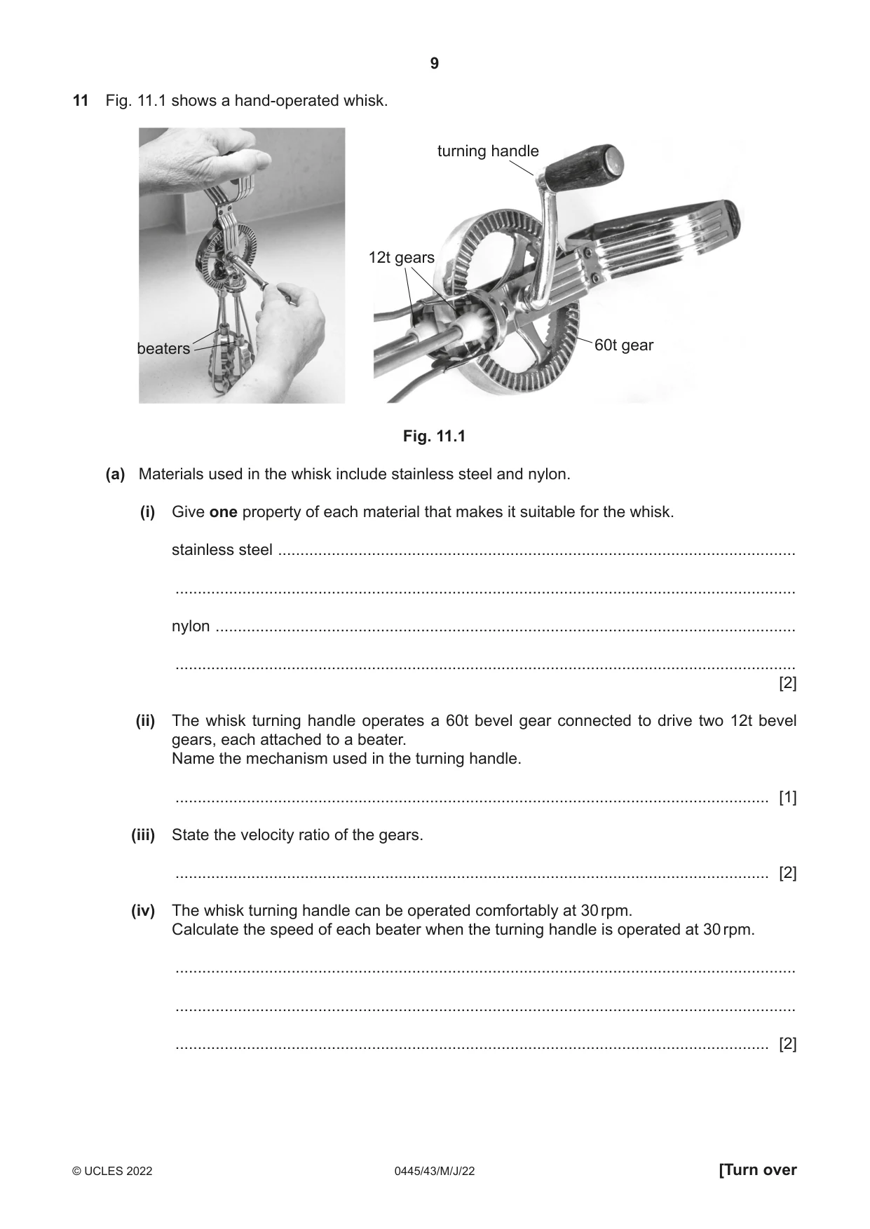
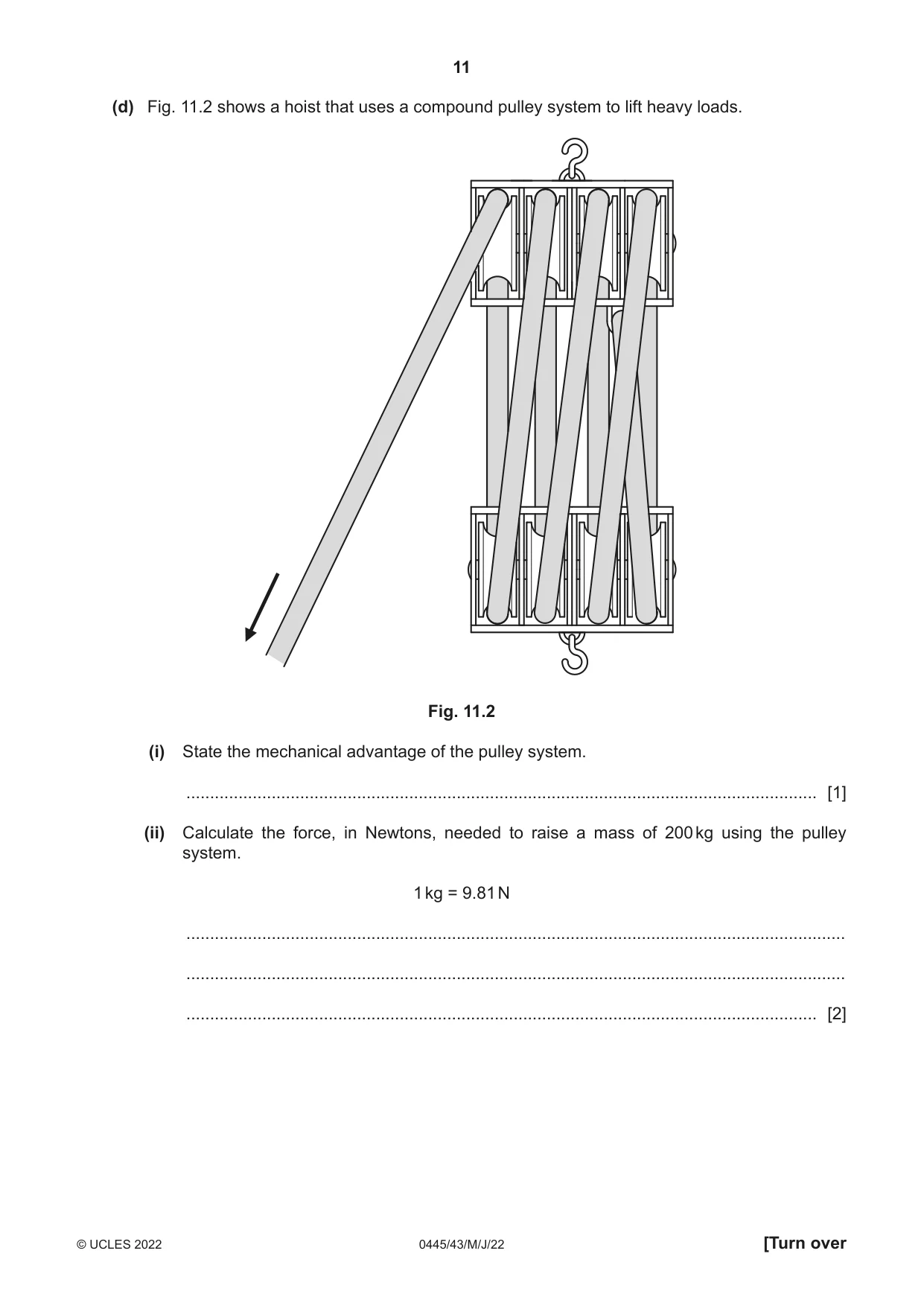
11 Fig. 11.1 shows a hand-operated whisk. turning handle 12t gears beaters 60t gear Fig. 11.1 (a) Materials used in the whisk include stainless steel and nylon. (i) Give one property of each material that makes it suitable for the whisk. stainless steel .................................................................................................................... ........................................................................................................................................... nylon .................................................................................................................................. ........................................................................................................................................... [2] (ii) The whisk turning handle operates a 60t bevel gear connected to drive two 12t bevel gears, each attached to a beater. Name the mechanism used in the turning handle. ..................................................................................................................................... [1] (iii) State the velocity ratio of the gears. ..................................................................................................................................... [2] (iv) The whisk turning handle can be operated comfortably at 30 rpm. Calculate the speed of each beater when the turning handle is operated at 30 rpm. ........................................................................................................................................... ........................................................................................................................................... ..................................................................................................................................... [2] (v) Describe the movement of one beater relative to the other. ........................................................................................................................................... ..................................................................................................................................... [2] (b) (i) Name three types of bearing commonly used in mechanisms. 1 ........................................................................................................................................ 2 ........................................................................................................................................ 3 ........................................................................................................................................ [3] (ii) Describe the purpose of a bearing in a mechanism. ........................................................................................................................................... ........................................................................................................................................... ..................................................................................................................................... [2] (iii) Use sketches and notes to show how a bearing can control end-to-end movement (thrust) on a shaft. [3] (c) (i) Describe the difference between a first, second and third order lever. ........................................................................................................................................... ........................................................................................................................................... ........................................................................................................................................... ..................................................................................................................................... [3] (ii) Explain why levers are important in hand operated machinery. ........................................................................................................................................... ........................................................................................................................................... ..................................................................................................................................... [2] (d) Fig. 11.2 shows a hoist that uses a compound pulley system to lift heavy loads. Fig. 11.2 (i) State the mechanical advantage of the pulley system. ..................................................................................................................................... [1] (ii) Calculate the force, in Newtons, needed to raise a mass of 200 kg using the pulley system. 1 kg = 9.81 N ........................................................................................................................................... ........................................................................................................................................... ..................................................................................................................................... [2]
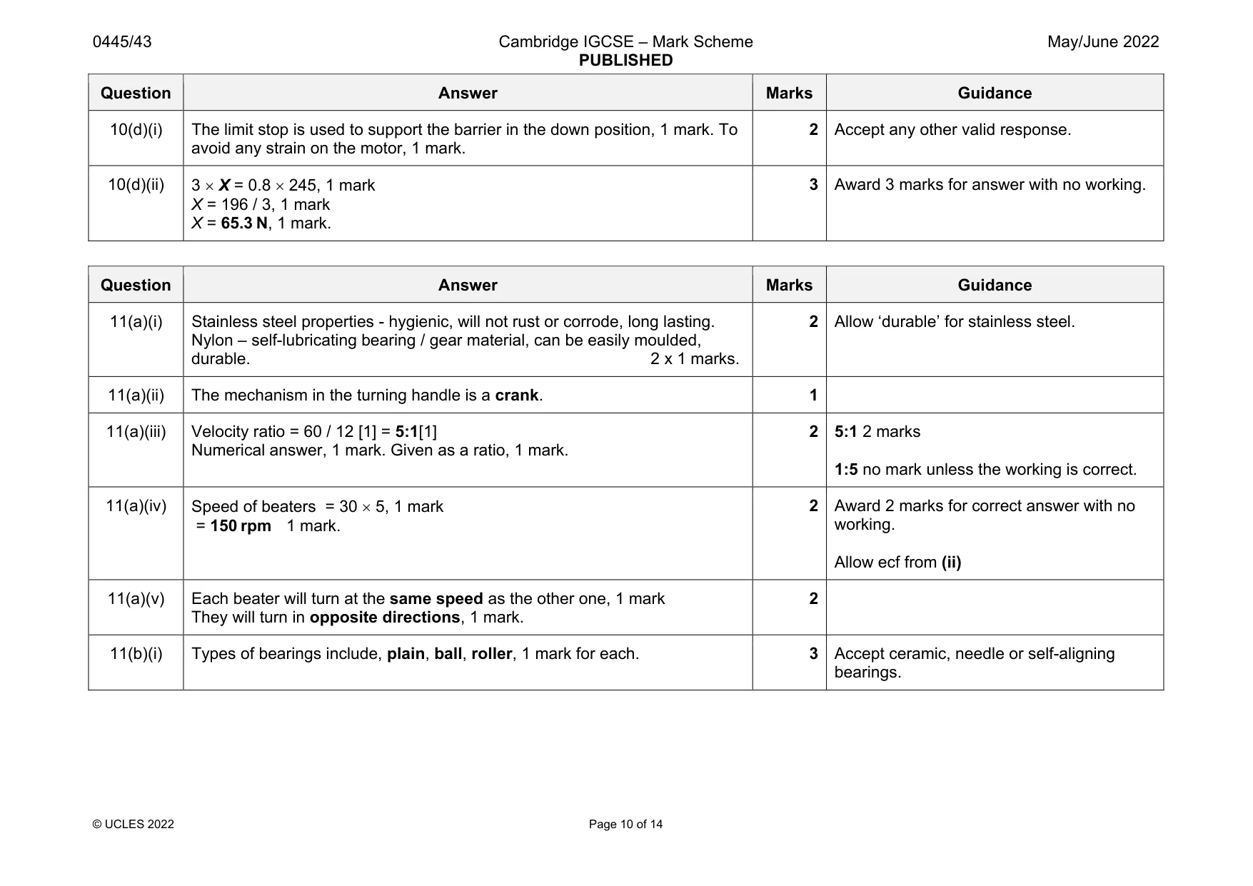
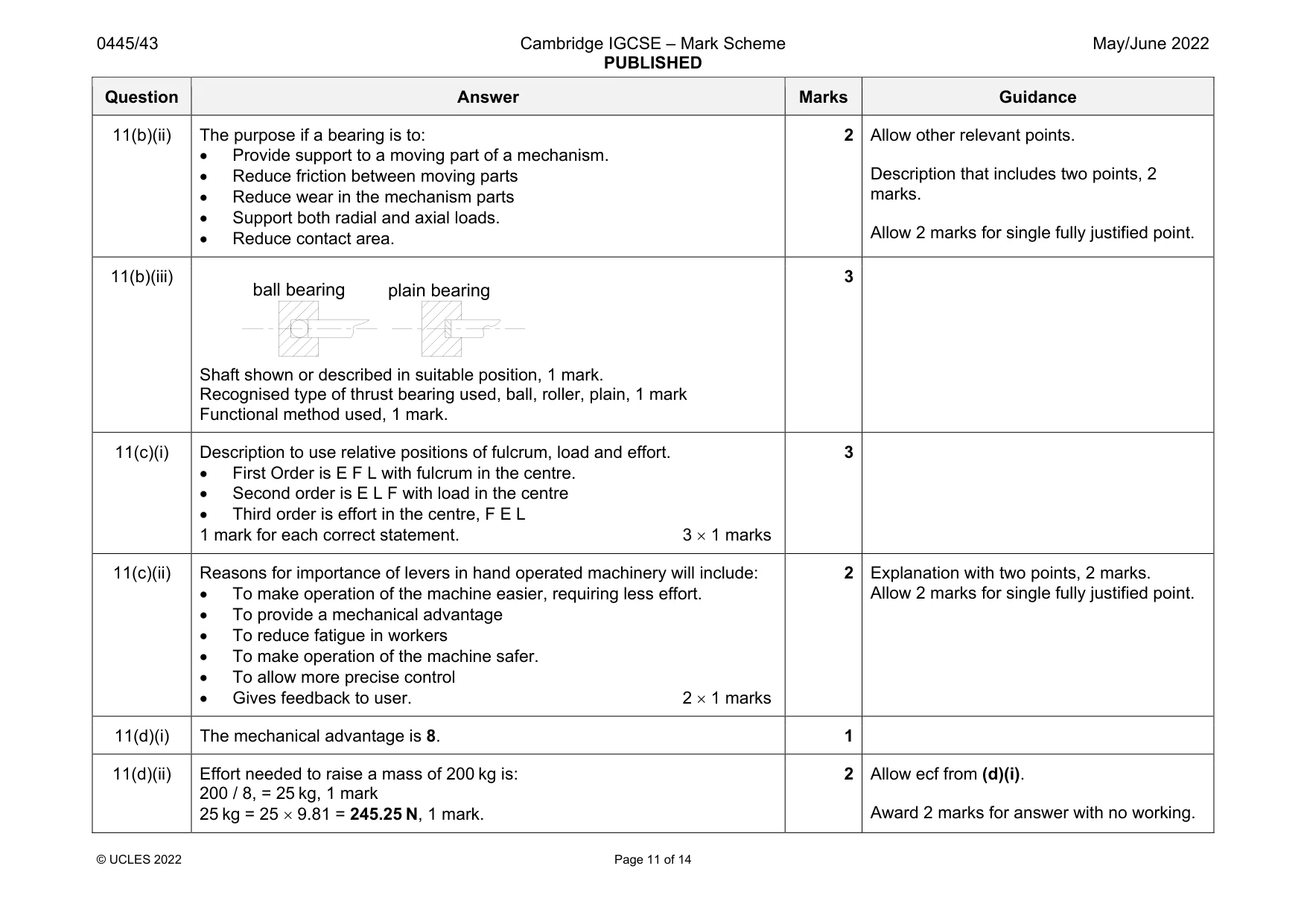
Mark scheme: 11(a)(i) Stainless steel properties - hygienic, will not rust or corrode, long lasting. Nylon – self-lubricating bearing / gear material, can be easily moulded, durable. 2 x 1 marks. 2 Allow ‘durable’ for stainless steel. 11(a)(ii) The mechanism in the turning handle is a crank. 1 11(a)(iii) Velocity ratio = 60 / 12 [1] = 5:1[1] Numerical answer, 1 mark. Given as a ratio, 1 mark. 2 5:1 2 marks 1:5 no mark unless the working is correct. 11(a)(iv) Speed of beaters = 30 5, 1 mark = 150 rpm 1 mark. 2 Award 2 marks for correct answer with no working. Allow ecf from (ii) 11(a)(v) Each beater will turn at the same speed as the other one, 1 mark They will turn in opposite directions, 1 mark. 2 11(b)(i) Types of bearings include, plain, ball, roller, 1 mark for each. 3 Accept ceramic, needle or self-aligning bearings. Question Answer Marks Guidance 11(b)(ii) The purpose if a bearing is to: Provide support to a moving part of a mechanism. Reduce friction between moving parts Reduce wear in the mechanism parts Support both radial and axial loads. Reduce contact area. 2 Allow other relevant points. Description that includes two points, 2 marks. Allow 2 marks for single fully justified point. 11(b)(iii) Shaft shown or described in suitable position, 1 mark. Recognised type of thrust bearing used, ball, roller, plain, 1 mark Functional method used, 1 mark. 3 11(c)(i) Description to use relative positions of fulcrum, load and effort. First Order is E F L with fulcrum in the centre. Second order is E L F with load in the centre Third order is effort in the centre, F E L 1 mark for each correct statement. 3 1 marks 3 11(c)(ii) Reasons for importance of levers in hand operated machinery will include: To make operation of the machine easier, requiring less effort. To provide a mechanical advantage To reduce fatigue in workers To make operation of the machine safer. To allow more precise control Gives feedback to user. 2 1 marks 2 Explanation with two points, 2 marks. Allow 2 marks for single fully justified point. 11(d)(i) The mechanical advantage is 8. 1 11(d)(ii) Effort needed to raise a mass of 200 kg is: 200 / 8, = 25 kg, 1 mark 25 kg = 25 9.81 = 245.25 N, 1 mark. 2 Allow ecf from (d)(i). Award 2 marks for answer with no working. ball bearing plain bearing
Q12 · An NPN transistor used as a switch
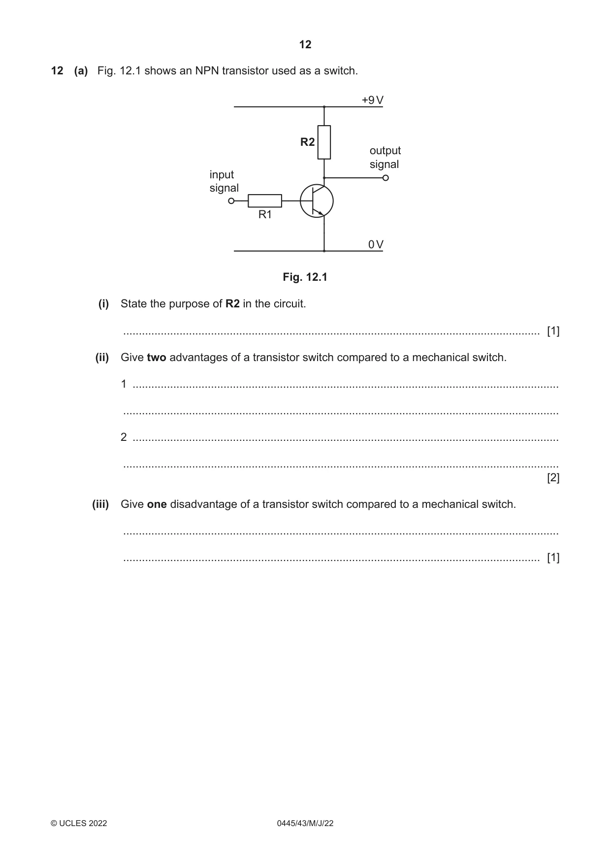
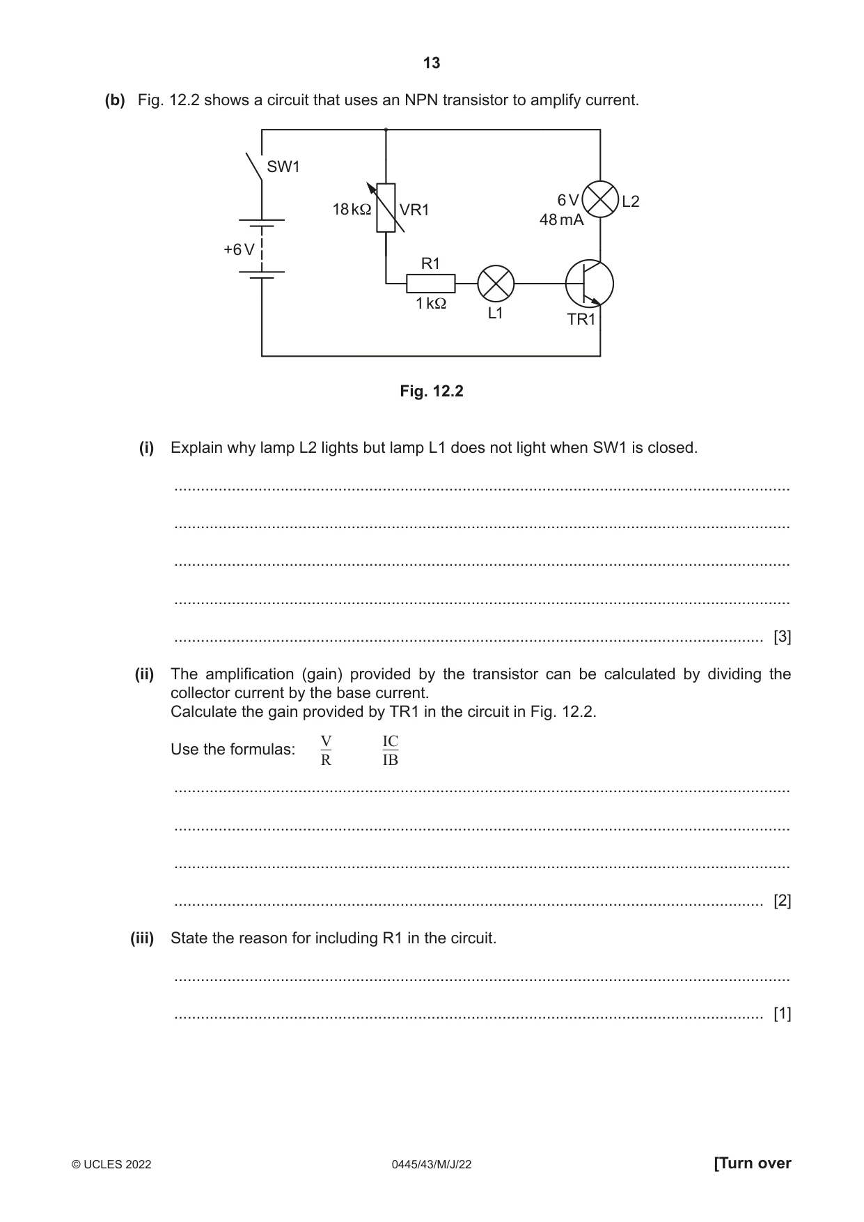
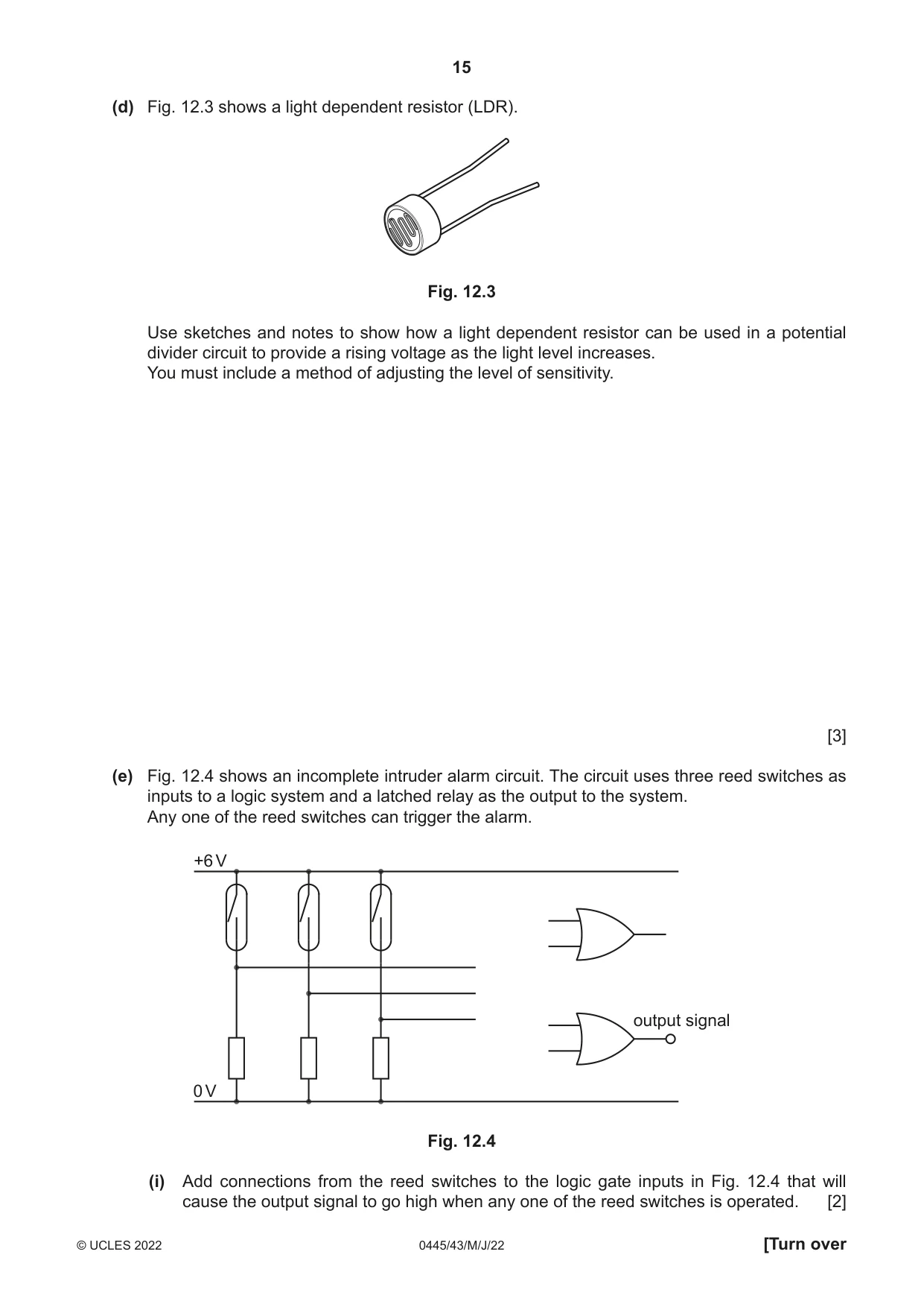
12 (a) Fig. 12.1 shows an NPN transistor used as a switch. +9 V R2 output signal input signal R1 0 V Fig. 12.1 (i) State the purpose of R2 in the circuit. ..................................................................................................................................... [1] (ii) Give two advantages of a transistor switch compared to a mechanical switch. 1 ........................................................................................................................................ ........................................................................................................................................... 2 ........................................................................................................................................ ........................................................................................................................................... [2] (iii) Give one disadvantage of a transistor switch compared to a mechanical switch. ........................................................................................................................................... ..................................................................................................................................... [1] (b) Fig. 12.2 shows a circuit that uses an NPN transistor to amplify current. SW1 6 V L2 18 kΩ VR1 48 mA +6 V R1 1 kΩ L1 TR1 Fig. 12.2 (i) Explain why lamp L2 lights but lamp L1 does not light when SW1 is closed. ........................................................................................................................................... ........................................................................................................................................... ........................................................................................................................................... ........................................................................................................................................... ..................................................................................................................................... [3] (ii) The amplification (gain) provided by the transistor can be calculated by dividing the collector current by the base current. Calculate the gain provided by TR1 in the circuit in Fig. 12.2. V IC Use the formulas: R IB ........................................................................................................................................... ........................................................................................................................................... ........................................................................................................................................... ..................................................................................................................................... [2] (iii) State the reason for including R1 in the circuit. ........................................................................................................................................... ..................................................................................................................................... [1] (c) LEDs have to be fitted in a circuit the correct way around. (i) Use sketches and notes to show how the legs of a standard LED can be identified so that it can be fitted correctly. [2] (ii) Describe how to identify the legs or connections on an integrated circuit (IC). ........................................................................................................................................... ........................................................................................................................................... ..................................................................................................................................... [2] (iii) Name three other electronic components that must be fitted in a circuit the correct way around. 1 ........................................................................................................................................ 2 ........................................................................................................................................ 3 ........................................................................................................................................ [3]
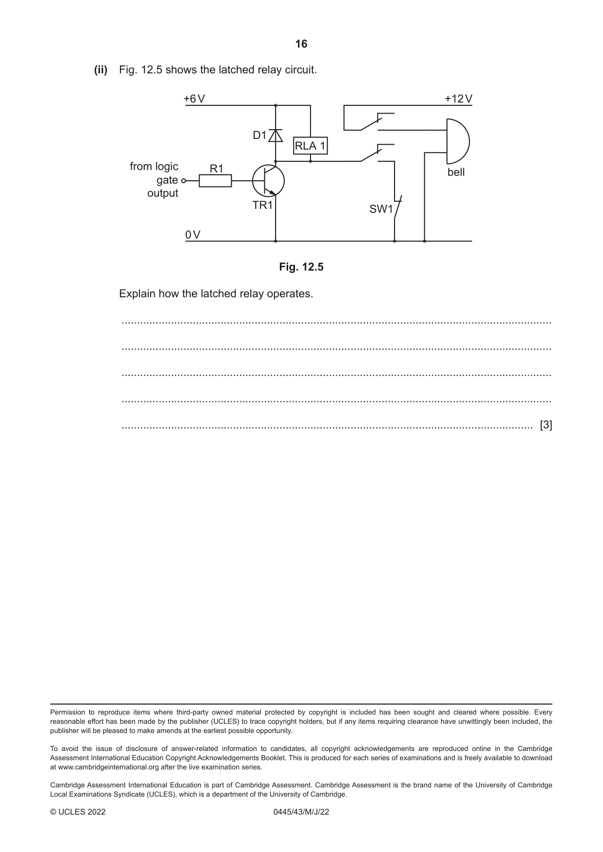
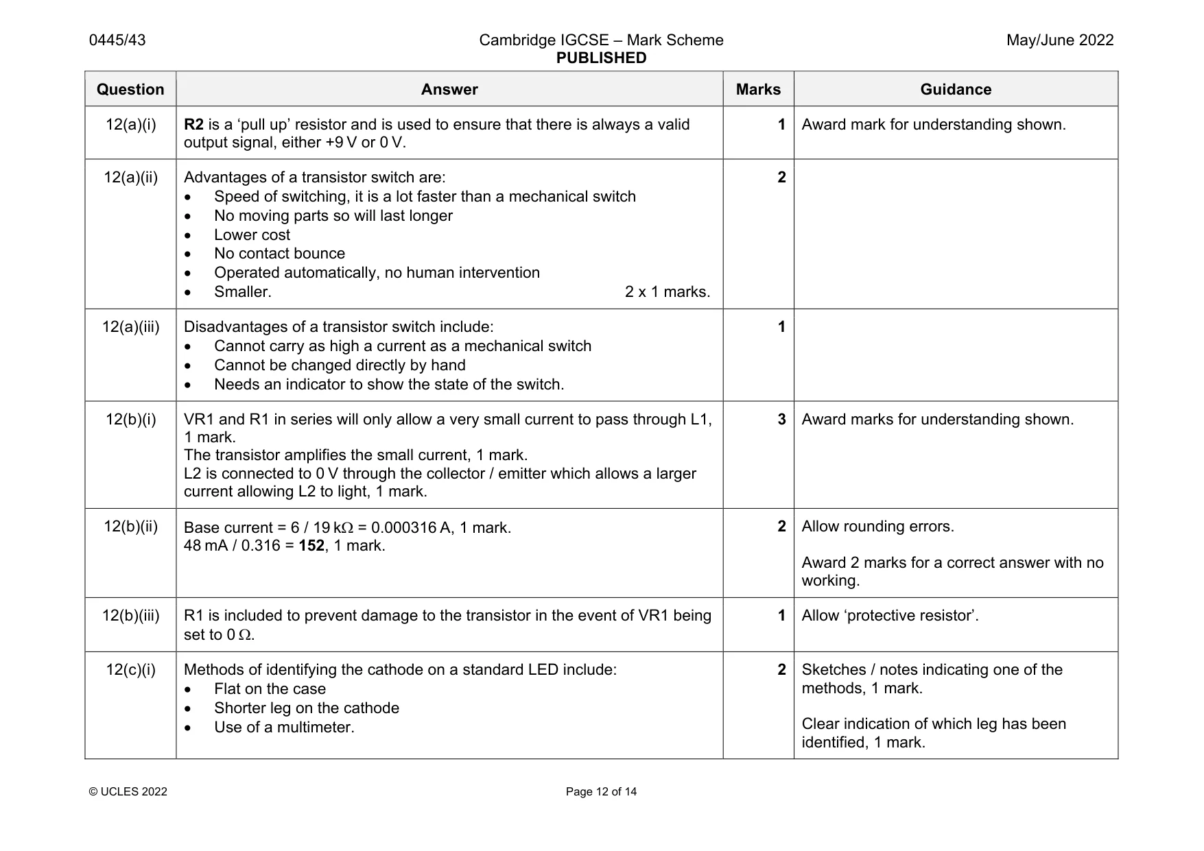
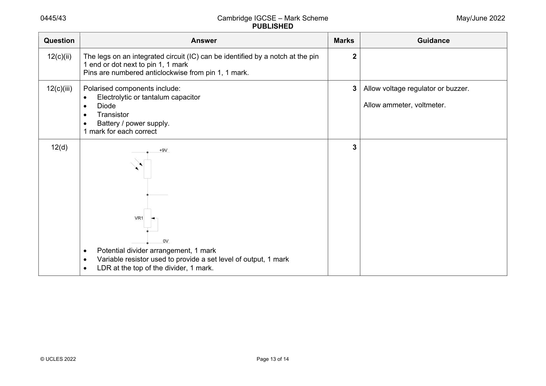
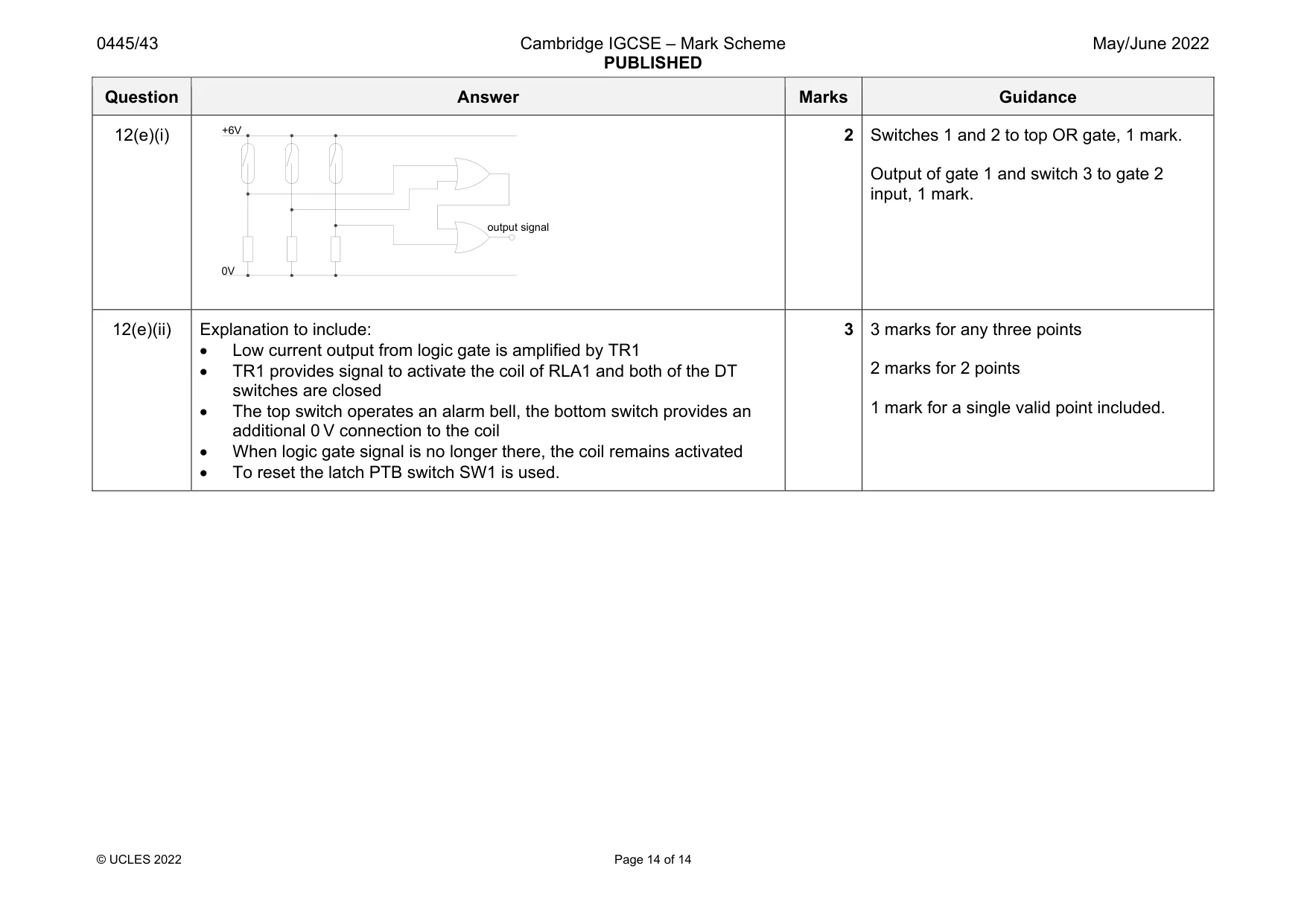
Mark scheme: 12(a)(i) R2 is a ‘pull up’ resistor and is used to ensure that there is always a valid output signal, either +9 V or 0 V. 1 Award mark for understanding shown. 12(a)(ii) Advantages of a transistor switch are: Speed of switching, it is a lot faster than a mechanical switch No moving parts so will last longer Lower cost No contact bounce Operated automatically, no human intervention Smaller. 2 x 1 marks. 2 12(a)(iii) Disadvantages of a transistor switch include: Cannot carry as high a current as a mechanical switch Cannot be changed directly by hand Needs an indicator to show the state of the switch. 1 12(b)(i) VR1 and R1 in series will only allow a very small current to pass through L1, 1 mark. The transistor amplifies the small current, 1 mark. L2 is connected to 0 V through the collector / emitter which allows a larger current allowing L2 to light, 1 mark. 3 Award marks for understanding shown. 12(b)(ii) Base current = 6 / 19 k = 0.000316 A, 1 mark. 48 mA / 0.316 = 152, 1 mark. 2 Allow rounding errors. Award 2 marks for a correct answer with no working. 12(b)(iii) R1 is included to prevent damage to the transistor in the event of VR1 being set to 0 . 1 Allow ‘protective resistor’. 12(c)(i) Methods of identifying the cathode on a standard LED include: Flat on the case Shorter leg on the cathode Use of a multimeter. 2 Sketches / notes indicating one of the methods, 1 mark. Clear indication of which leg has been identified, 1 mark. Question Answer Marks Guidance 12(c)(ii) The legs on an integrated circuit (IC) can be identified by a notch at the pin 1 end or dot next to pin 1, 1 mark Pins are numbered anticlockwise from pin 1, 1 mark. 2 12(c)(iii) Polarised components include: Electrolytic or tantalum capacitor Diode Transistor Battery / power supply. 1 mark for each correct 3 Allow voltage regulator or buzzer. Allow ammeter, voltmeter. 12(d) Potential divider arrangement, 1 mark Variable resistor used to provide a set level of output, 1 mark LDR at the top of the divider, 1 mark. 3 +9V 0V VR1 Question Answer Marks Guidance 12(e)(i) 2 Switches 1 and 2 to top OR gate, 1 mark. Output of gate 1 and switch 3 to gate 2 input, 1 mark. 12(e)(ii) Explanation to include: Low current output from logic gate is amplified by TR1 TR1 provides signal to activate the coil of RLA1 and both of the DT switches are closed The top switch operates an alarm bell, the bottom switch provides an additional 0 V connection to the coil When logic gate signal is no longer there, the coil remains activated To reset the latch PTB switch SW1 is used. 3 3 marks for any three points 2 marks for 2 points 1 mark for a single valid point included. output signal 0V +6V
What was in this paper
The subtopics covered by these 12 questions, and how many questions each got. Open one in a new tab to see every Cambridge question on it.
What you needed in this session
Cambridge’s own grade thresholds for 2022 May/June, Paper 4 · Variant 3. A higher threshold means an easier paper — the bar moves with how the cohort did.