Cambridge IGCSE Design and Technology 0445 — 2025 May/June Paper 4 · Variant 2
0445/42/M/J/25 · 11 questions · 50 marks · 60 min
The question paper and its mark scheme, free to read here and free to download. This is Cambridge’s own paper, exactly as it was sat.
Question paper20 pages

Mark scheme16 pages
Answers below. Sit the paper first if you are practising.
Questions as text
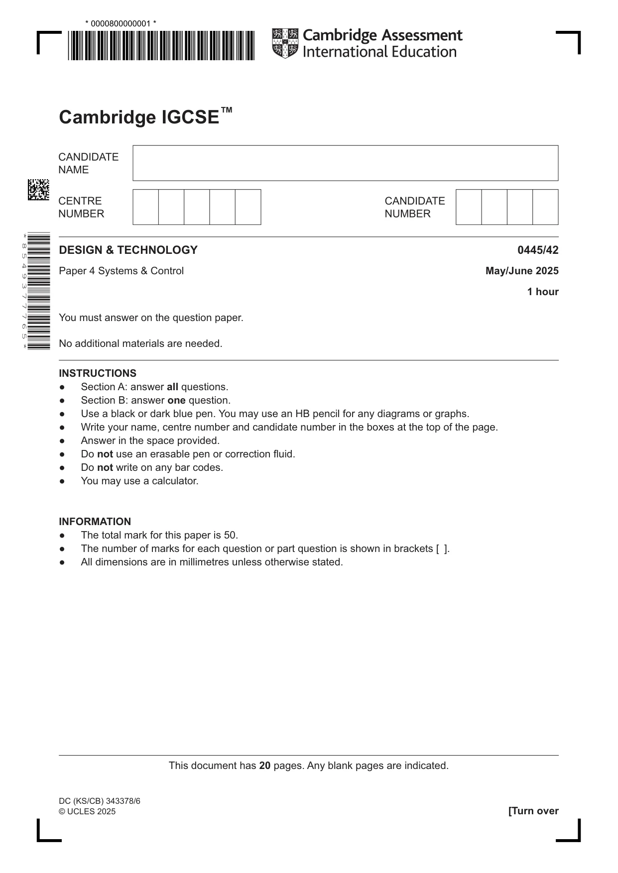
Q1 · Add two ticks (✓) to each item, A, B and C, in Fig
1 Add two ticks (✓) to each item, A, B and C, in Fig. 1.1 to identify the type of structure and if it is man‑made or natural. A B C frame shell mass man‑made natural Fig. 1.1 [6]
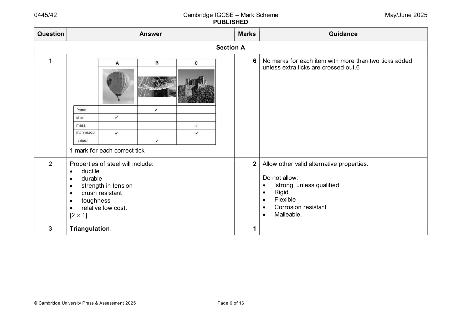
Mark scheme: Question Answer Marks Guidance Section A 1 6 No marks for each item with more than two ticks added unless extra ticks are crossed out.6 1 mark for each correct tick
Q2 · Suspension bridges are often supported by steel cables
2 Suspension bridges are often supported by steel cables. Give two properties of steel that make it suitable for use in cables. 1 ....................................................................................................................................................... 2 ....................................................................................................................................................... [2]
Mark scheme: 2 Properties of steel will include: 2 Allow other valid alternative properties. • ductile • durable Do not allow: • strength in tension • ‘strong’ unless qualified • crush resistant • Rigid • toughness • Flexible • relative low cost. • Corrosion resistant [2 1] • Malleable.
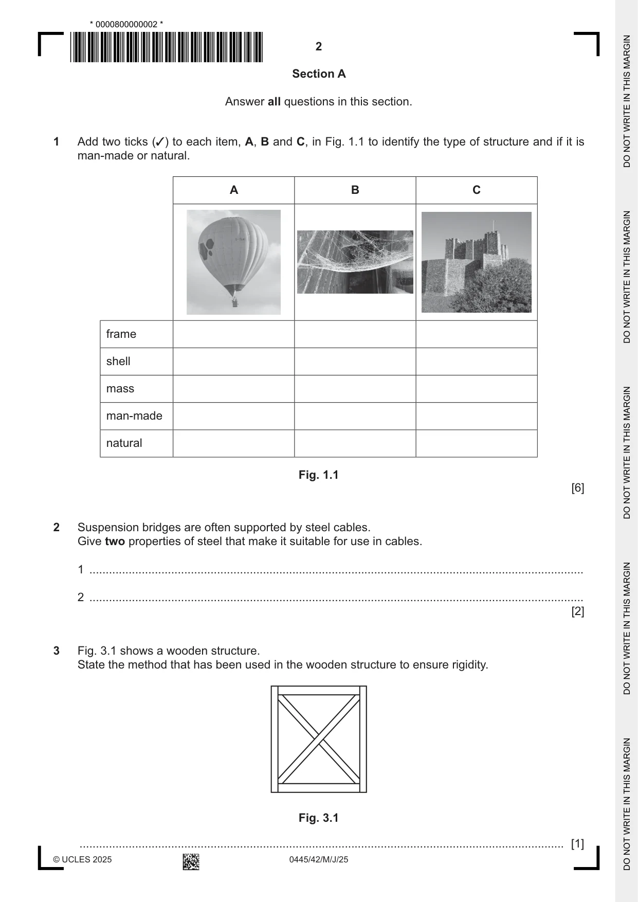
Question 3
3 Fig. 3.1 shows a wooden structure. State the method that has been used in the wooden structure to ensure rigidity. Fig. 3.1 .................................................................................................................................................... [1]
Mark scheme: 3 Triangulation. 1
Q4 · Friction can be reduced by design
4 Friction can be reduced by design. Give two examples of how friction can be reduced when designing a car. 1 ....................................................................................................................................................... .......................................................................................................................................................... 2 ....................................................................................................................................................... .......................................................................................................................................................... [2]
Mark scheme: 4 Friction can be reduced by: 2 Accept any other valid response • use of a streamlined / aerodynamic shape • making mating surfaces smoother Description should relate to car design, do not allow • reducing contact between surfaces reference to oil or grease. • use of efficient bearings • use of materials with a low coefficient of friction • reduced weight / parts count • accuracy in manufacture [2 1]
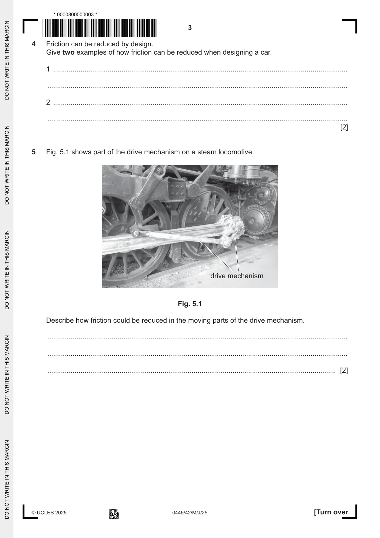
Q5 · Part of the drive mechanism on a steam locomotive
5 Fig. 5.1 shows part of the drive mechanism on a steam locomotive. drive mechanism Fig. 5.1 Describe how friction could be reduced in the moving parts of the drive mechanism. .......................................................................................................................................................... .......................................................................................................................................................... .................................................................................................................................................... [2]
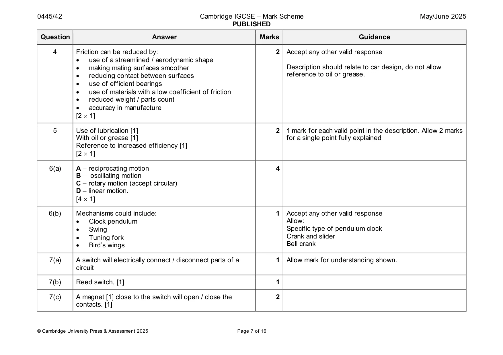
Mark scheme: 5 Use of lubrication [1] 2 1 mark for each valid point in the description. Allow 2 marks With oil or grease [1] for a single point fully explained Reference to increased efficiency [1] [2 1]
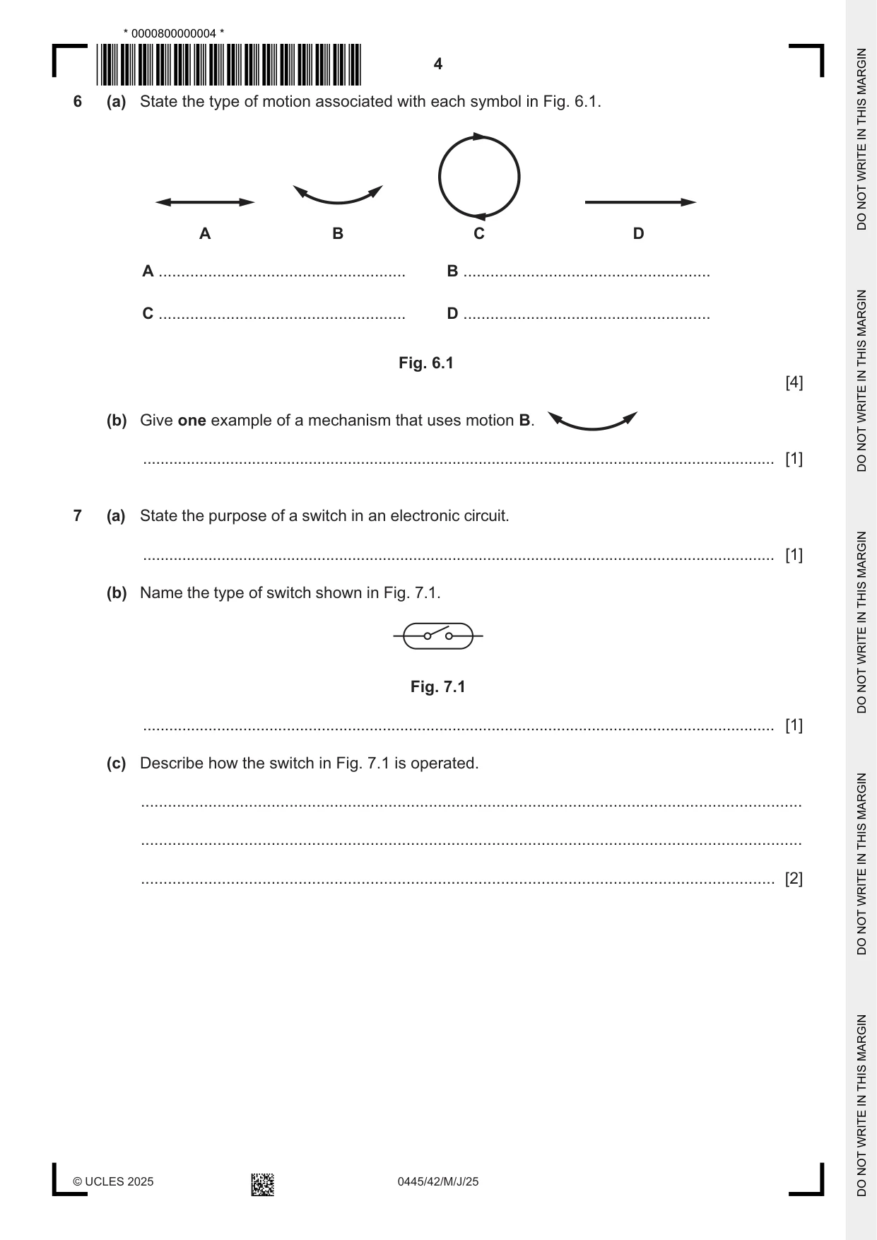
Q6 · State the type of motion associated with each symbol in Fig
6 (a) State the type of motion associated with each symbol in Fig. 6.1. A B C D A ....................................................... B ....................................................... C ....................................................... D ....................................................... Fig. 6.1 [4] (b) Give one example of a mechanism that uses motion B. ................................................................................................................................................. [1]
Mark scheme: 6(a) A – reciprocating motion 4 B – oscillating motion C – rotary motion (accept circular) D – linear motion. [4 1] 6(b) Mechanisms could include: 1 Accept any other valid response • Clock pendulum Allow: • Swing Specific type of pendulum clock • Tuning fork Crank and slider • Bird’s wings Bell crank
Q7 · State the purpose of a switch in an electronic circuit
7 (a) State the purpose of a switch in an electronic circuit. ................................................................................................................................................. [1] (b) Name the type of switch shown in Fig. 7.1. Fig. 7.1 ................................................................................................................................................. [1] (c) Describe how the switch in Fig. 7.1 is operated. ................................................................................................................................................... ................................................................................................................................................... ............................................................................................................................................. [2]
Mark scheme: 7(a) A switch will electrically connect / disconnect parts of a 1 Allow mark for understanding shown. circuit 7(b) Reed switch, [1] 1 7(c) A magnet [1] close to the switch will open / close the 2 contacts. [1]
Q8 · Multiple and submultiple voltage values
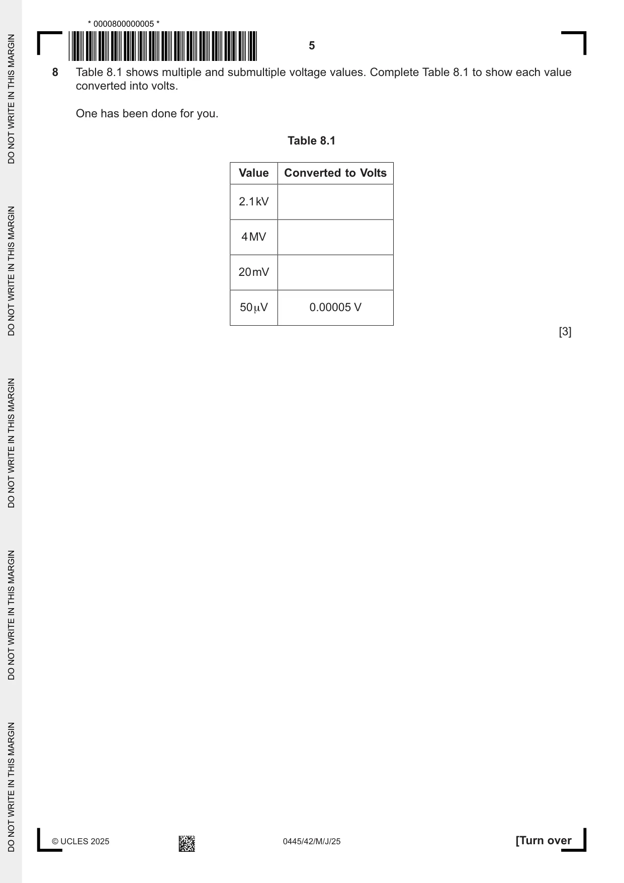
8 Table 8.1 shows multiple and submultiple voltage values. Complete Table 8.1 to show each value converted into volts. One has been done for you. Table 8.1 Value Converted to Volts 2.1 kV 4 MV 20 mV 50 μV 0.00005 V [3]
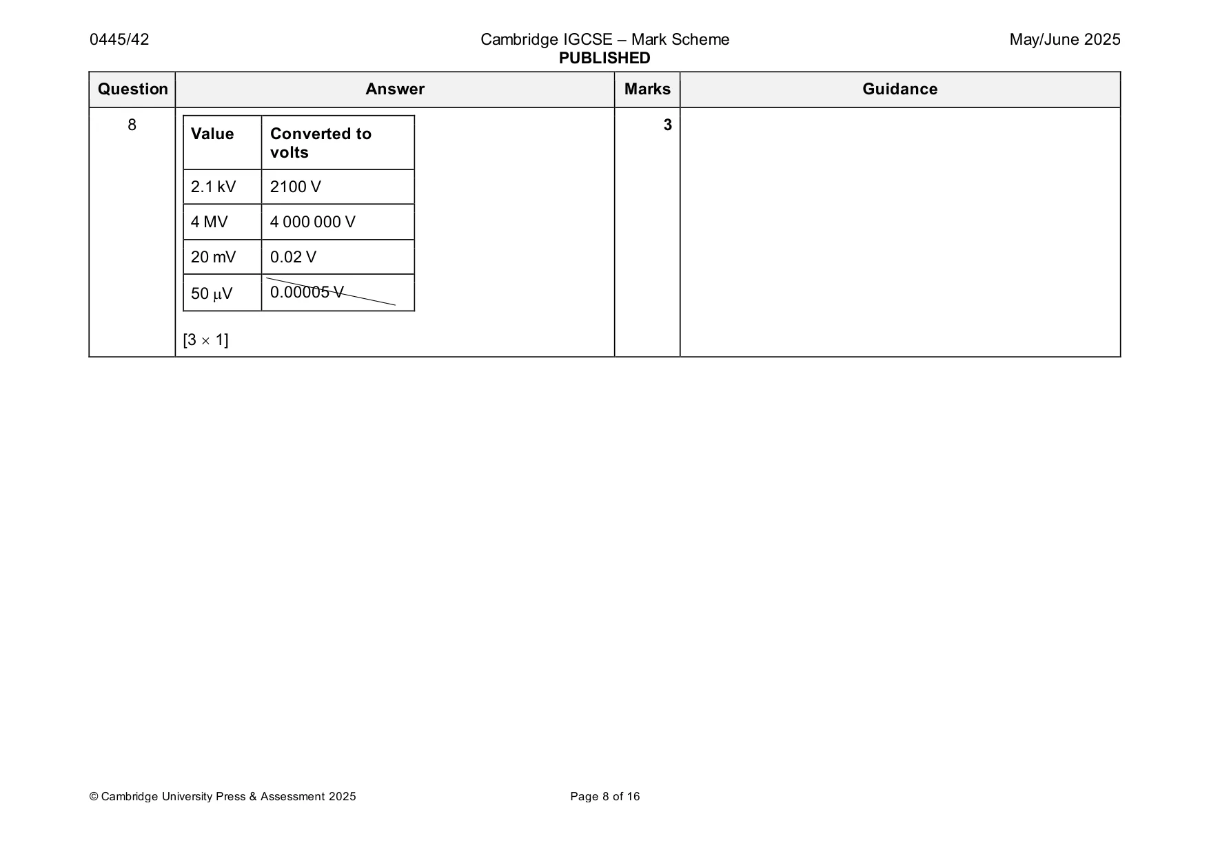
Mark scheme: 8 3 Value Converted to volts 2.1 kV 2100 V 4 MV 4 000 000 V 20 mV 0.02 V 50 V 0.00005 V [3 1]
Q9 · State what is meant by a ‘moment’ in a structure
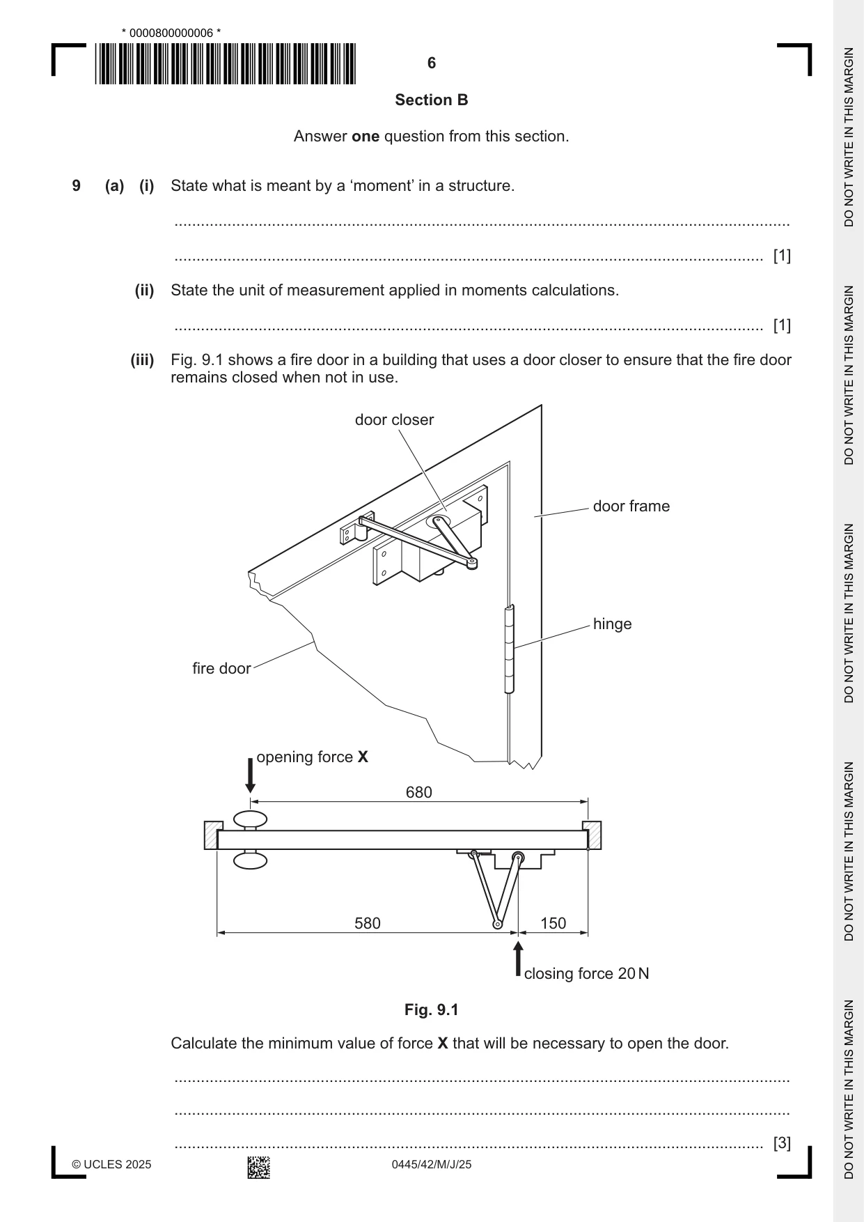
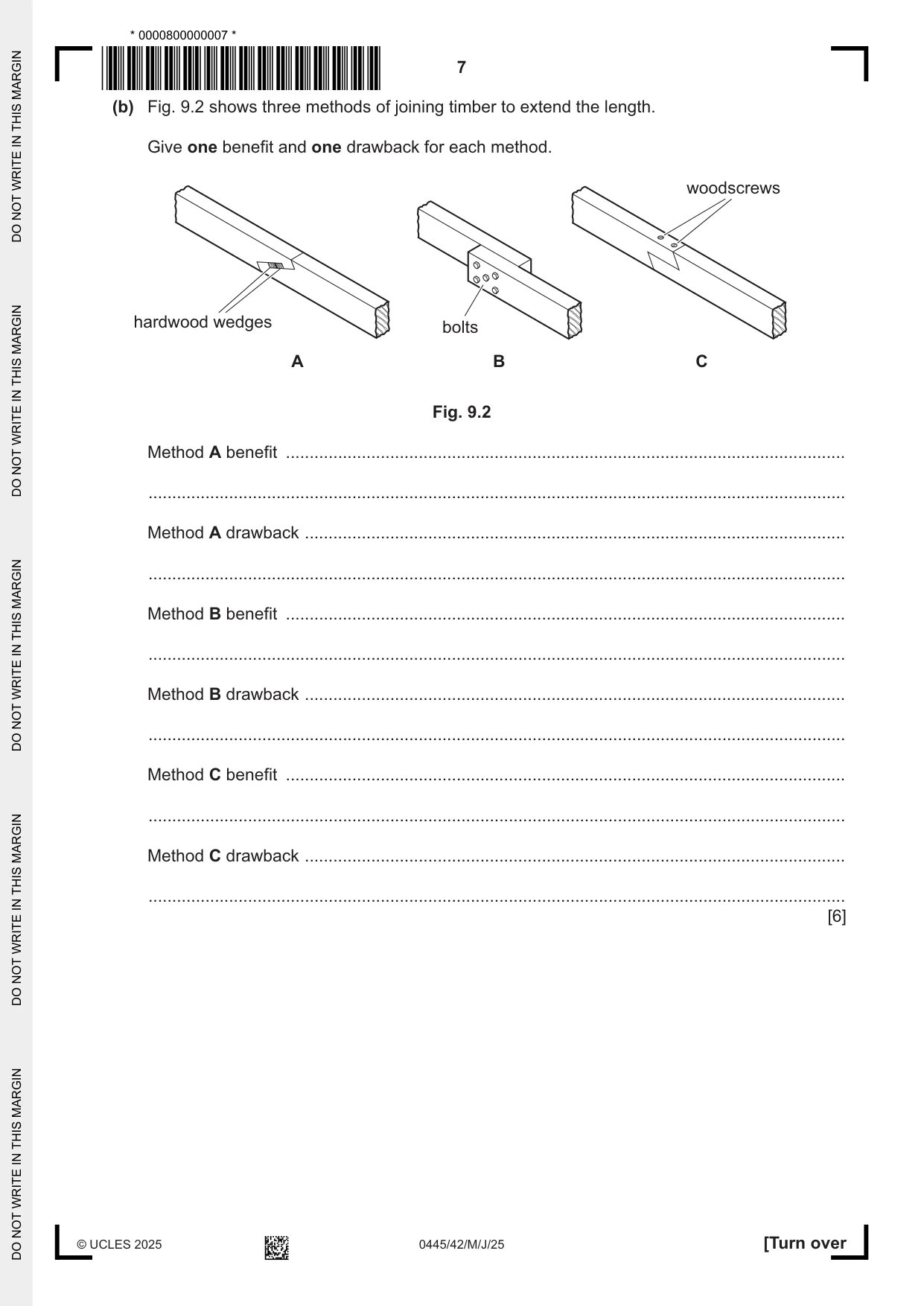
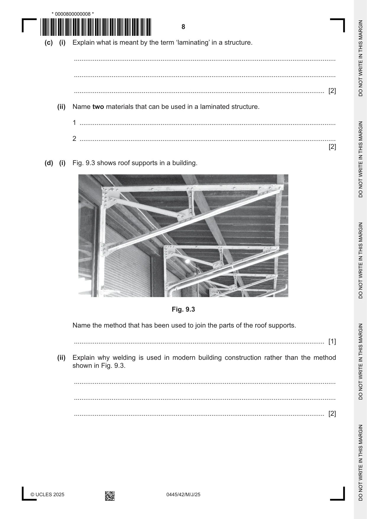
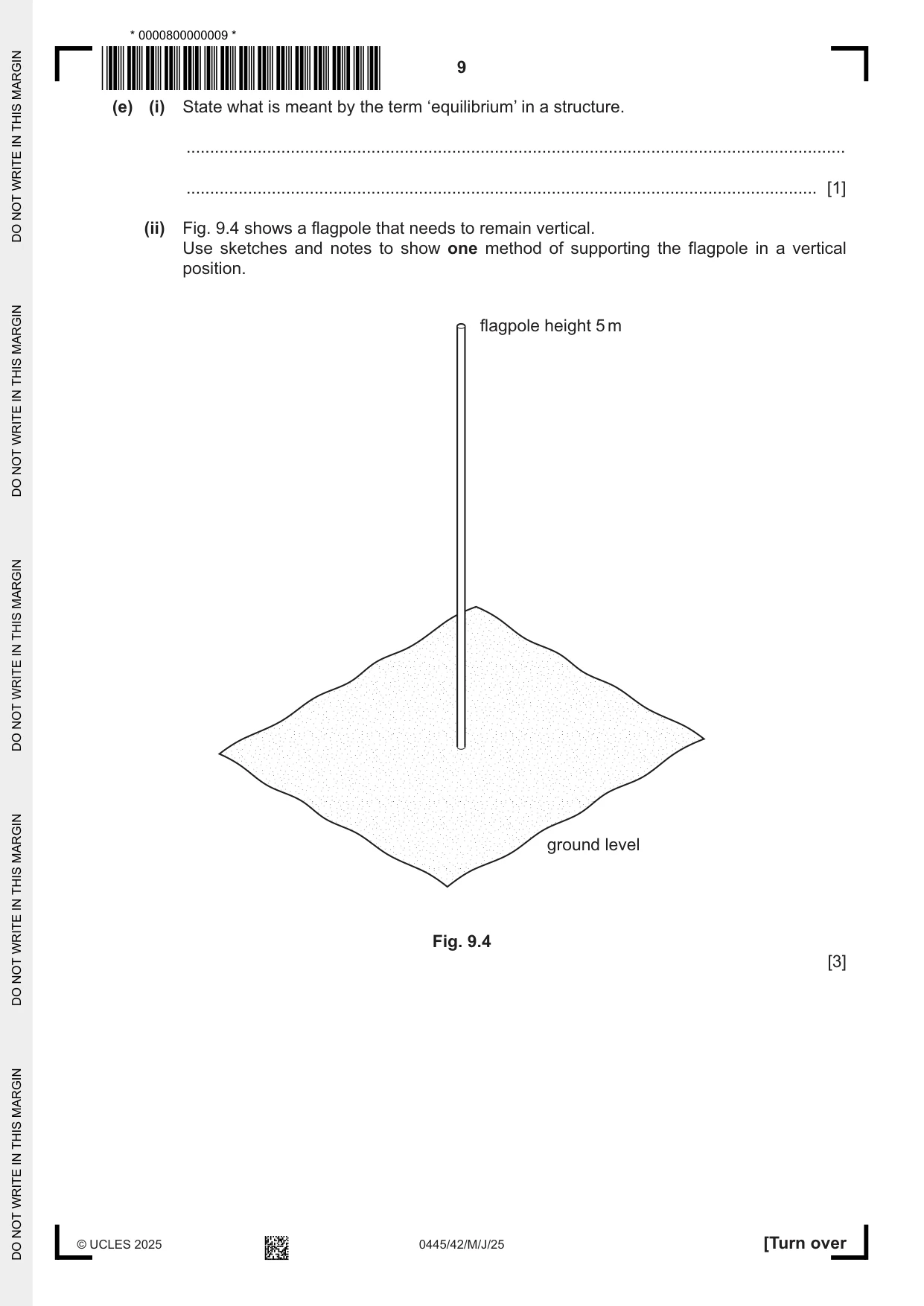
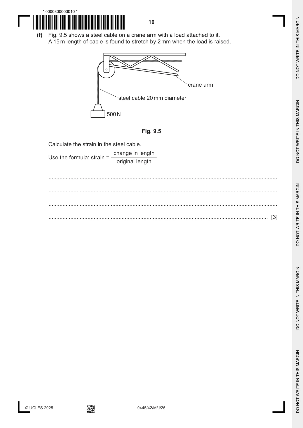
9 (a) (i) State what is meant by a ‘moment’ in a structure. ........................................................................................................................................... ..................................................................................................................................... [1] (ii) State the unit of measurement applied in moments calculations. ..................................................................................................................................... [1] (iii) Fig. 9.1 shows a fire door in a building that uses a door closer to ensure that the fire door remains closed when not in use. door closer door frame hinge fire door opening force X 680 580 150 closing force 20 N Fig. 9.1 Calculate the minimum value of force X that will be necessary to open the door. ........................................................................................................................................... ........................................................................................................................................... ..................................................................................................................................... [3] (b) Fig. 9.2 shows three methods of joining timber to extend the length. Give one benefit and one drawback for each method. woodscrews hardwood wedges bolts A B C Fig. 9.2 Method A benefit ...................................................................................................................... ................................................................................................................................................... Method A drawback .................................................................................................................. ................................................................................................................................................... Method B benefit ...................................................................................................................... ................................................................................................................................................... Method B drawback .................................................................................................................. ................................................................................................................................................... Method C benefit ...................................................................................................................... ................................................................................................................................................... Method C drawback .................................................................................................................. ................................................................................................................................................... [6] (c) (i) Explain what is meant by the term ‘laminating’ in a structure. ........................................................................................................................................... ........................................................................................................................................... ..................................................................................................................................... [2] (ii) Name two materials that can be used in a laminated structure. 1 ........................................................................................................................................ 2 ........................................................................................................................................ [2] (d) (i) Fig. 9.3 shows roof supports in a building. Fig. 9.3 Name the method that has been used to join the parts of the roof supports. ..................................................................................................................................... [1] (ii) Explain why welding is used in modern building construction rather than the method shown in Fig. 9.3. ........................................................................................................................................... ........................................................................................................................................... ..................................................................................................................................... [2] (e) (i) State what is meant by the term ‘equilibrium’ in a structure. ........................................................................................................................................... ..................................................................................................................................... [1] (ii) Fig. 9.4 shows a flagpole that needs to remain vertical. Use sketches and notes to show one method of supporting the flagpole in a vertical position. flagpole height 5 m ground level Fig. 9.4 [3] (f) Fig. 9.5 shows a steel cable on a crane arm with a load attached to it. A 15 m length of cable is found to stretch by 2 mm when the load is raised. crane arm steel cable 20 mm diameter 500 N Fig. 9.5 Calculate the strain in the steel cable. change in length Use the formula: strain = original length ................................................................................................................................................... ................................................................................................................................................... ................................................................................................................................................... ............................................................................................................................................. [3]
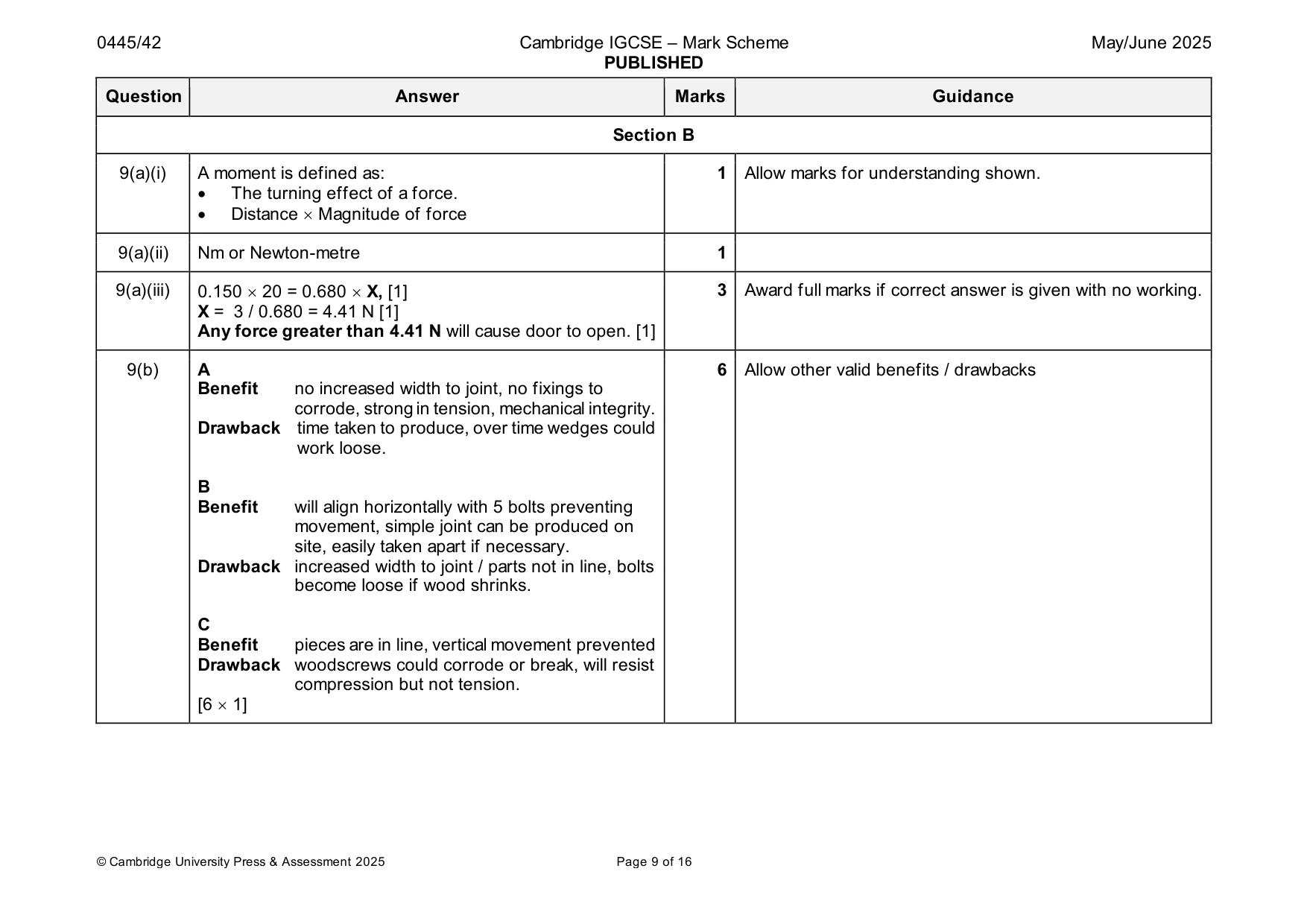
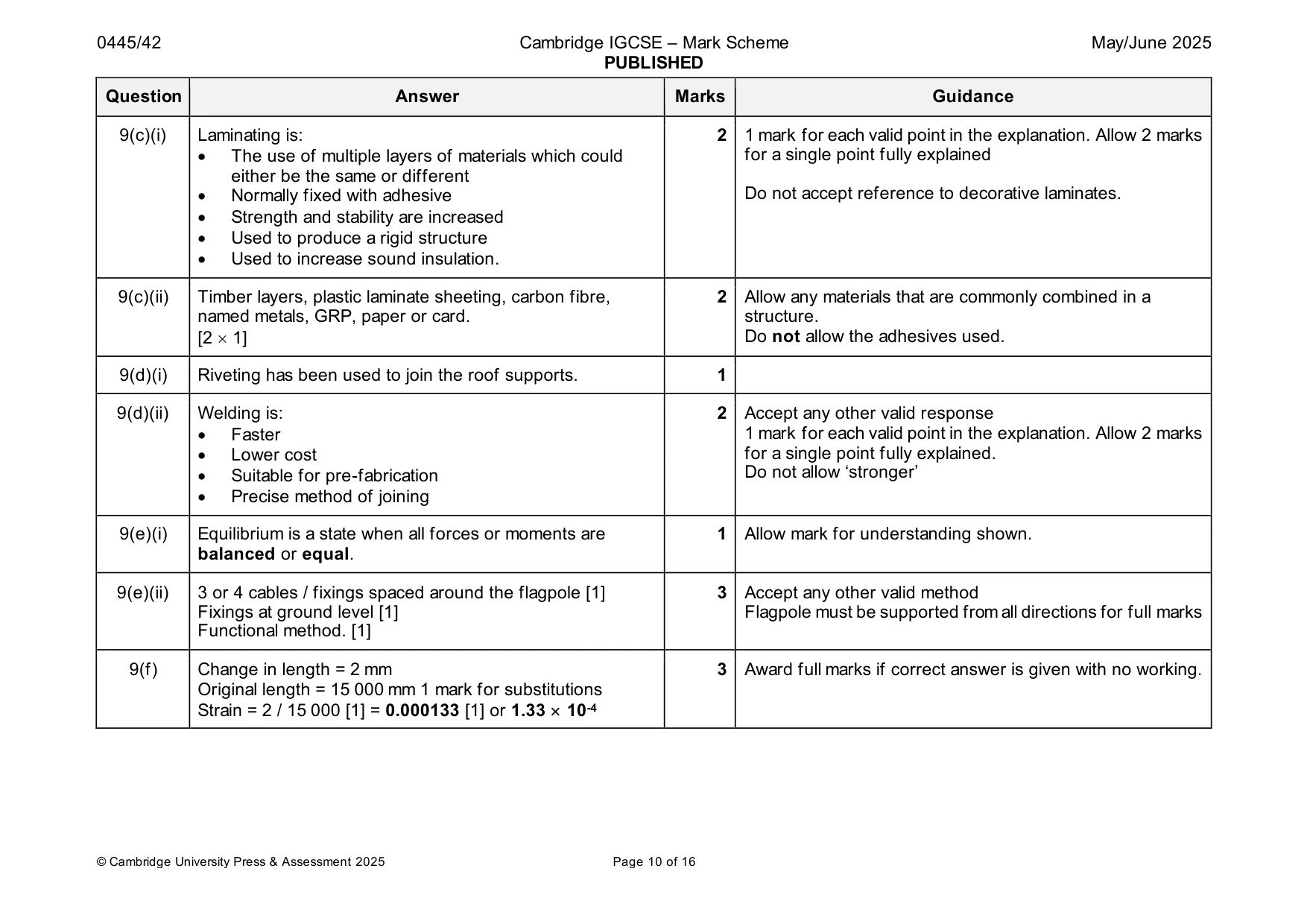
Mark scheme: 9(a)(i) A moment is defined as: 1 Allow marks for understanding shown. • The turning effect of a force. • Distance Magnitude of force 9(a)(ii) Nm or Newton-metre 1 9(a)(iii) 0.150 20 = 0.680 X, [1] 3 Award full marks if correct answer is given with no working. X = 3 / 0.680 = 4.41 N [1] Any force greater than 4.41 N will cause door to open. [1] 9(b) A 6 Allow other valid benefits / drawbacks Benefit no increased width to joint, no fixings to corrode, strong in tension, mechanical integrity. Drawback time taken to produce, over time wedges could work loose. B Benefit will align horizontally with 5 bolts preventing movement, simple joint can be produced on site, easily taken apart if necessary. Drawback increased width to joint / parts not in line, bolts become loose if wood shrinks. C Benefit pieces are in line, vertical movement prevented Drawback woodscrews could corrode or break, will resist compression but not tension. [6 1] 9(c)(i) Laminating is: 2 1 mark for each valid point in the explanation. Allow 2 marks • The use of multiple layers of materials which could for a single point fully explained either be the same or different • Normally fixed with adhesive Do not accept reference to decorative laminates. • Strength and stability are increased • Used to produce a rigid structure • Used to increase sound insulation. 9(c)(ii) Timber layers, plastic laminate sheeting, carbon fibre, 2 Allow any materials that are commonly combined in a named metals, GRP, paper or card. structure. [2 1] Do not allow the adhesives used. 9(d)(i) Riveting has been used to join the roof supports. 1 9(d)(ii) Welding is: 2 Accept any other valid response • Faster 1 mark for each valid point in the explanation. Allow 2 marks • Lower cost for a single point fully explained. • Suitable for pre-fabrication Do not allow ‘stronger’ • Precise method of joining 9(e)(i) Equilibrium is a state when all forces or moments are 1 Allow mark for understanding shown. balanced or equal. 9(e)(ii) 3 or 4 cables / fixings spaced around the flagpole [1] 3 Accept any other valid method Fixings at ground level [1] Flagpole must be supported from all directions for full marks Functional method. [1] 9(f) Change in length = 2 mm 3 Award full marks if correct answer is given with no working. Original length = 15 000 mm 1 mark for substitutions Strain = 2 / 15 000 [1] = 0.000133 [1] or 1.33 10-4
Q10 · A pair of garden loppers used to cut branches from trees
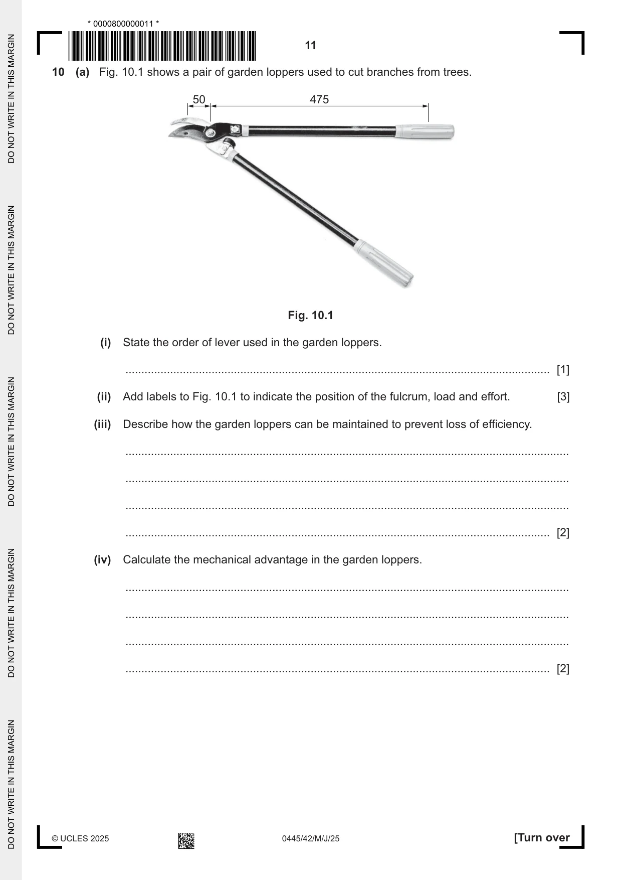
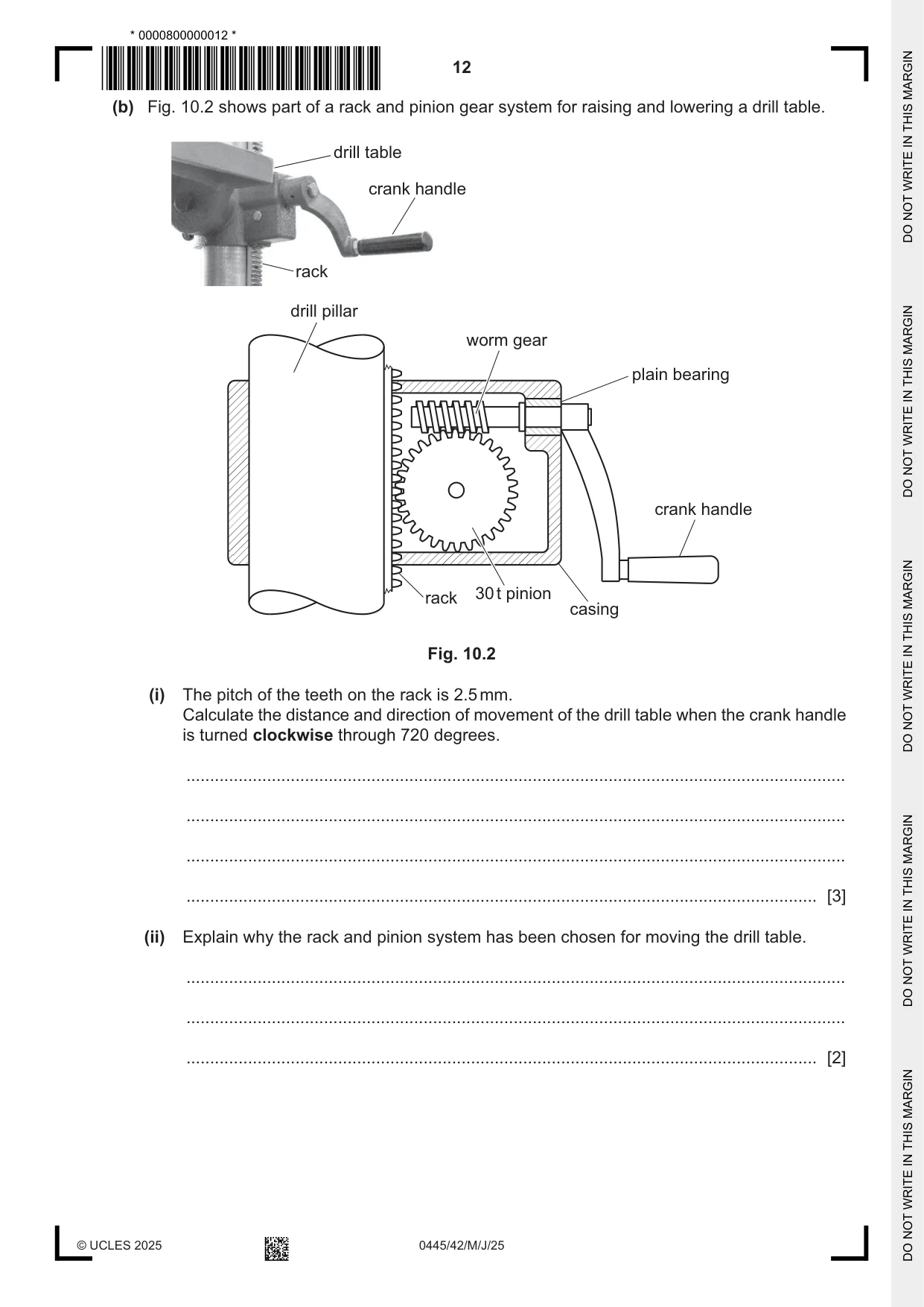
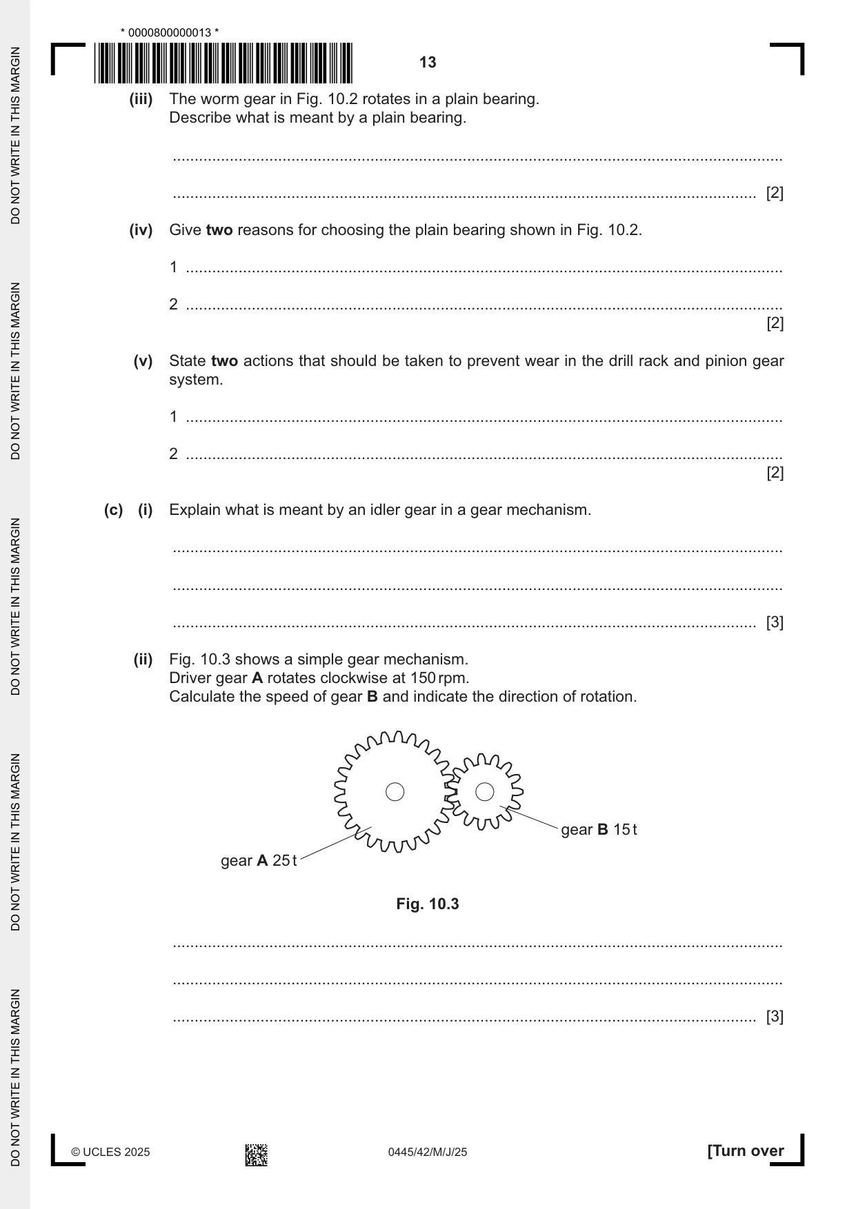
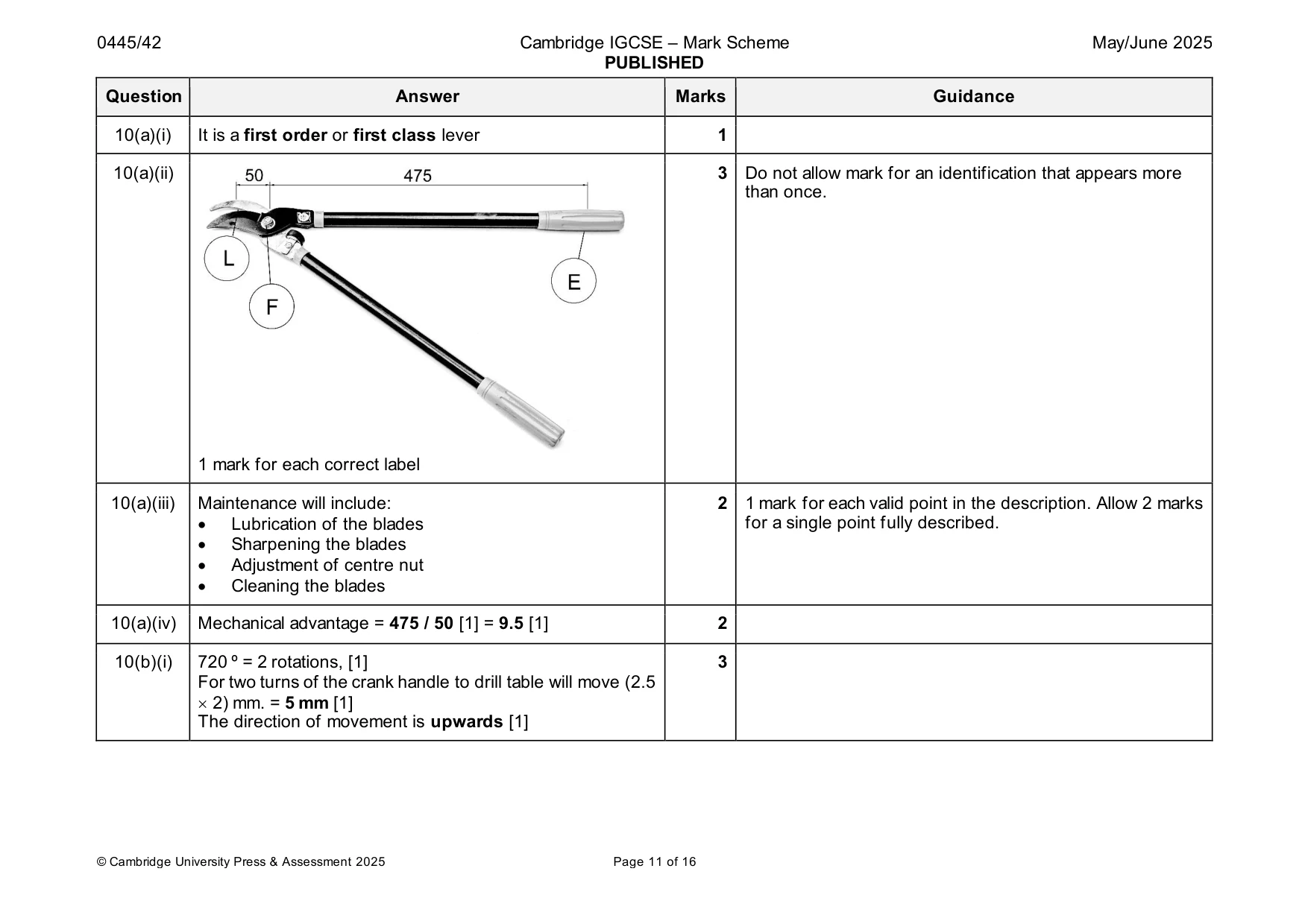
10 (a) Fig. 10.1 shows a pair of garden loppers used to cut branches from trees. 50 475 Fig. 10.1 (i) State the order of lever used in the garden loppers. ..................................................................................................................................... [1] (ii) Add labels to Fig. 10.1 to indicate the position of the fulcrum, load and effort. [3] (iii) Describe how the garden loppers can be maintained to prevent loss of efficiency. ........................................................................................................................................... ........................................................................................................................................... ........................................................................................................................................... ..................................................................................................................................... [2] (iv) Calculate the mechanical advantage in the garden loppers. ........................................................................................................................................... ........................................................................................................................................... ........................................................................................................................................... ..................................................................................................................................... [2] (b) Fig. 10.2 shows part of a rack and pinion gear system for raising and lowering a drill table. drill table crank handle rack drill pillar worm gear plain bearing crank handle rack 30 t pinion casing Fig. 10.2 (i) The pitch of the teeth on the rack is 2.5 mm. Calculate the distance and direction of movement of the drill table when the crank handle is turned clockwise through 720 degrees. ........................................................................................................................................... ........................................................................................................................................... ........................................................................................................................................... ..................................................................................................................................... [3] (ii) Explain why the rack and pinion system has been chosen for moving the drill table. ........................................................................................................................................... ........................................................................................................................................... ..................................................................................................................................... [2] (iii) The worm gear in Fig. 10.2 rotates in a plain bearing. Describe what is meant by a plain bearing. ........................................................................................................................................... ..................................................................................................................................... [2] (iv) Give two reasons for choosing the plain bearing shown in Fig. 10.2. 1 ........................................................................................................................................ 2 ........................................................................................................................................ [2] (v) State two actions that should be taken to prevent wear in the drill rack and pinion gear system. 1 ........................................................................................................................................ 2 ........................................................................................................................................ [2] (c) (i) Explain what is meant by an idler gear in a gear mechanism. ........................................................................................................................................... ........................................................................................................................................... ..................................................................................................................................... [3] (ii) Fig. 10.3 shows a simple gear mechanism. Driver gear A rotates clockwise at 150 rpm. Calculate the speed of gear B and indicate the direction of rotation. gear B 15 t gear A 25 t Fig. 10.3 ........................................................................................................................................... ........................................................................................................................................... ..................................................................................................................................... [3]
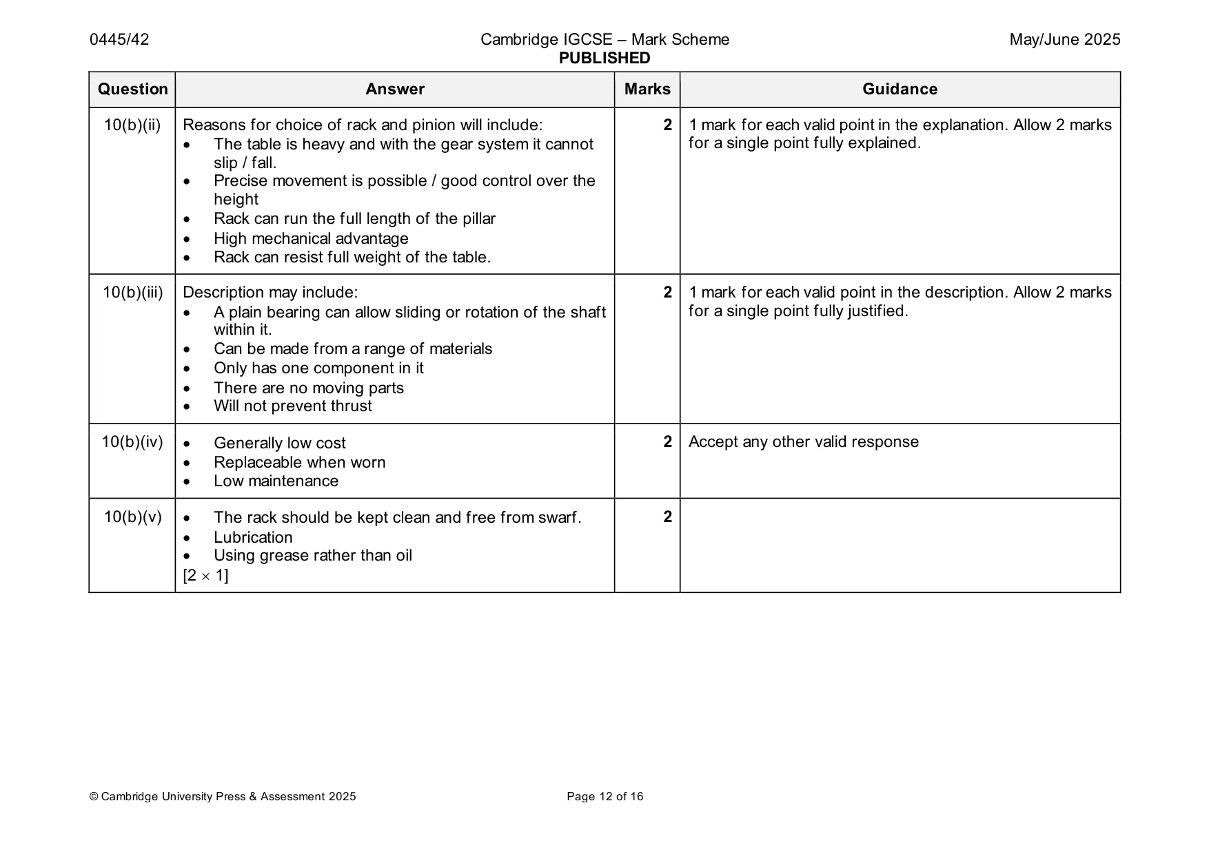
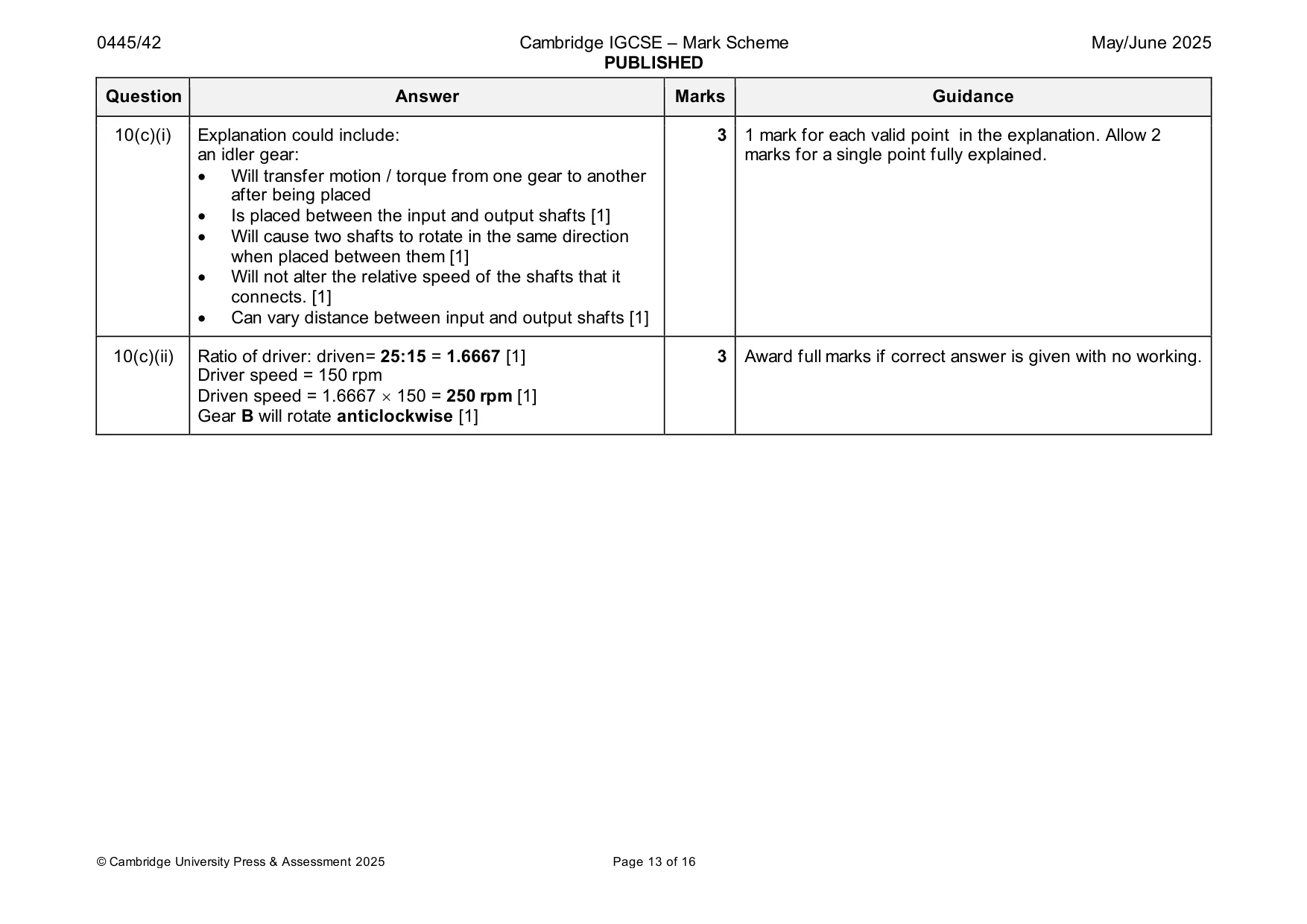
Mark scheme: 10(a)(i) It is a first order or first class lever 1 10(a)(ii) 3 Do not allow mark for an identification that appears more than once. 1 mark for each correct label 10(a)(iii) Maintenance will include: 2 1 mark for each valid point in the description. Allow 2 marks • Lubrication of the blades for a single point fully described. • Sharpening the blades • Adjustment of centre nut • Cleaning the blades 10(a)(iv) Mechanical advantage = 475 / 50 [1] = 9.5 [1] 2 10(b)(i) 720 º = 2 rotations, [1] 3 For two turns of the crank handle to drill table will move (2.5 2) mm. = 5 mm [1] The direction of movement is upwards [1] 10(b)(ii) Reasons for choice of rack and pinion will include: 2 1 mark for each valid point in the explanation. Allow 2 marks • The table is heavy and with the gear system it cannot for a single point fully explained. slip / fall. • Precise movement is possible / good control over the height • Rack can run the full length of the pillar • High mechanical advantage • Rack can resist full weight of the table. 10(b)(iii) Description may include: 2 1 mark for each valid point in the description. Allow 2 marks • A plain bearing can allow sliding or rotation of the shaft for a single point fully justified. within it. • Can be made from a range of materials • Only has one component in it • There are no moving parts • Will not prevent thrust 10(b)(iv) • Generally low cost 2 Accept any other valid response • Replaceable when worn • Low maintenance 10(b)(v) • The rack should be kept clean and free from swarf. 2 • Lubrication • Using grease rather than oil [2 1] 10(c)(i) Explanation could include: 3 1 mark for each valid point in the explanation. Allow 2 an idler gear: marks for a single point fully explained. • Will transfer motion / torque from one gear to another after being placed • Is placed between the input and output shafts [1] • Will cause two shafts to rotate in the same direction when placed between them [1] • Will not alter the relative speed of the shafts that it connects. [1] • Can vary distance between input and output shafts [1] 10(c)(ii) Ratio of driver: driven= 25:15 = 1.6667 [1] 3 Award full marks if correct answer is given with no working. Driver speed = 150 rpm Driven speed = 1.6667 150 = 250 rpm [1] Gear B will rotate anticlockwise [1]
Q11 · Two incomplete light‑emitting diode (LED) circuits
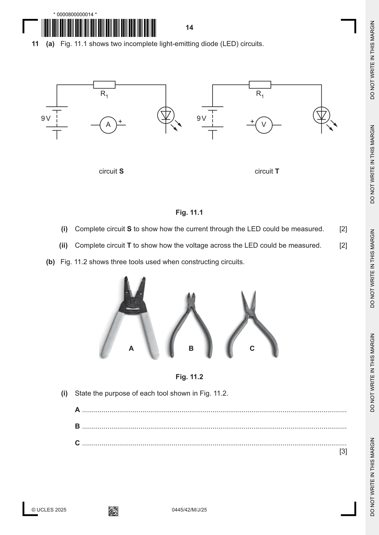
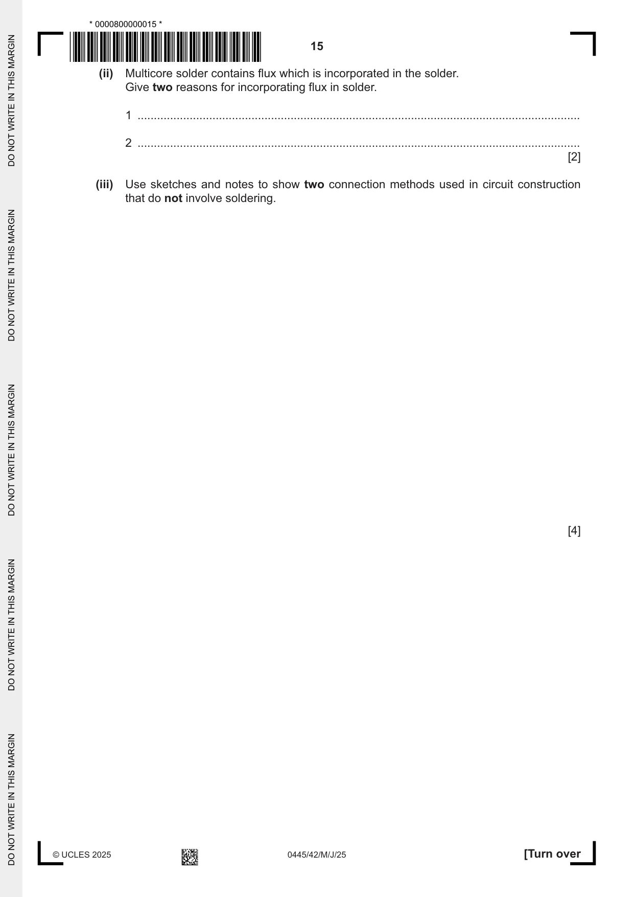
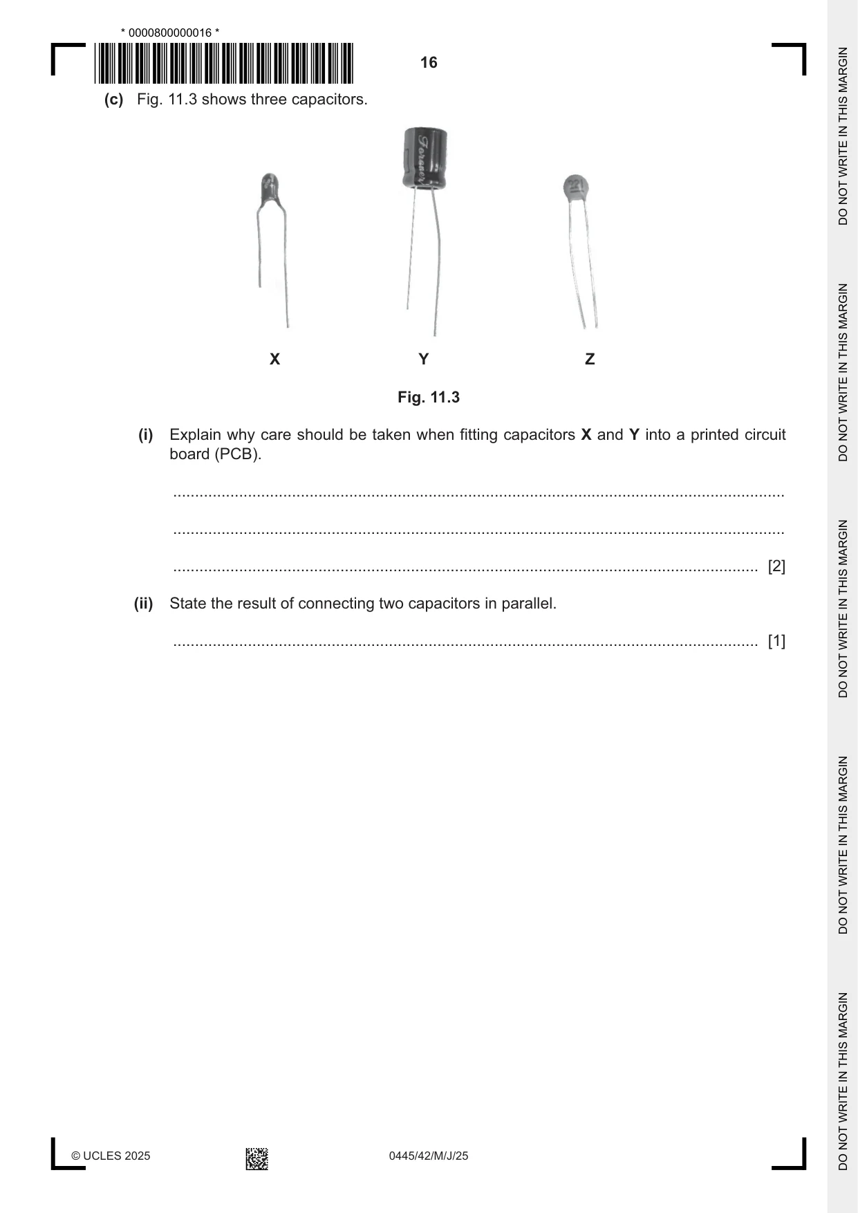
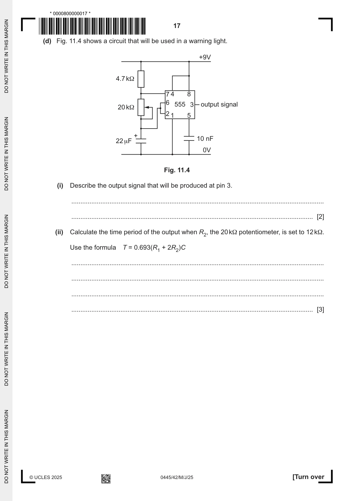
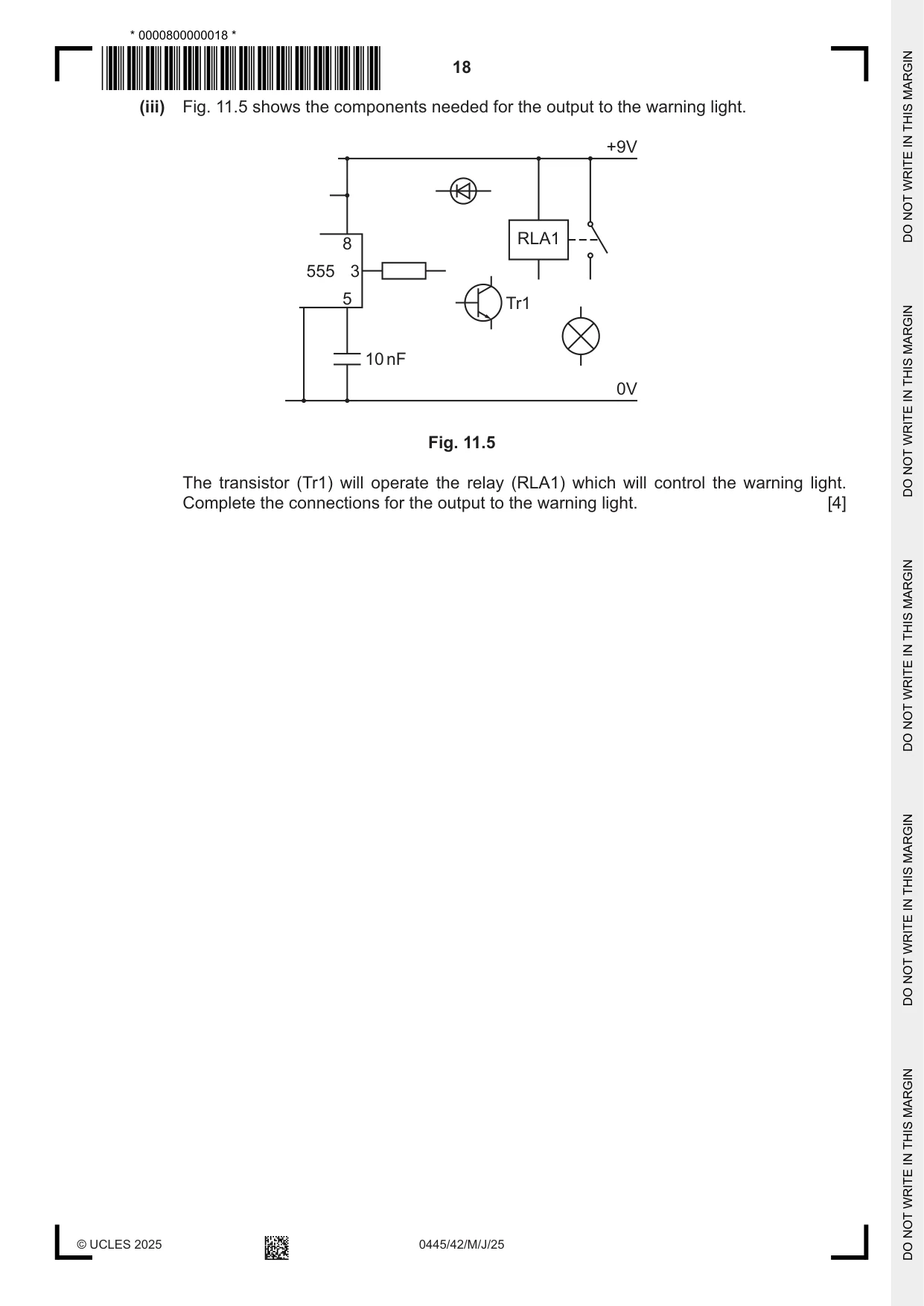
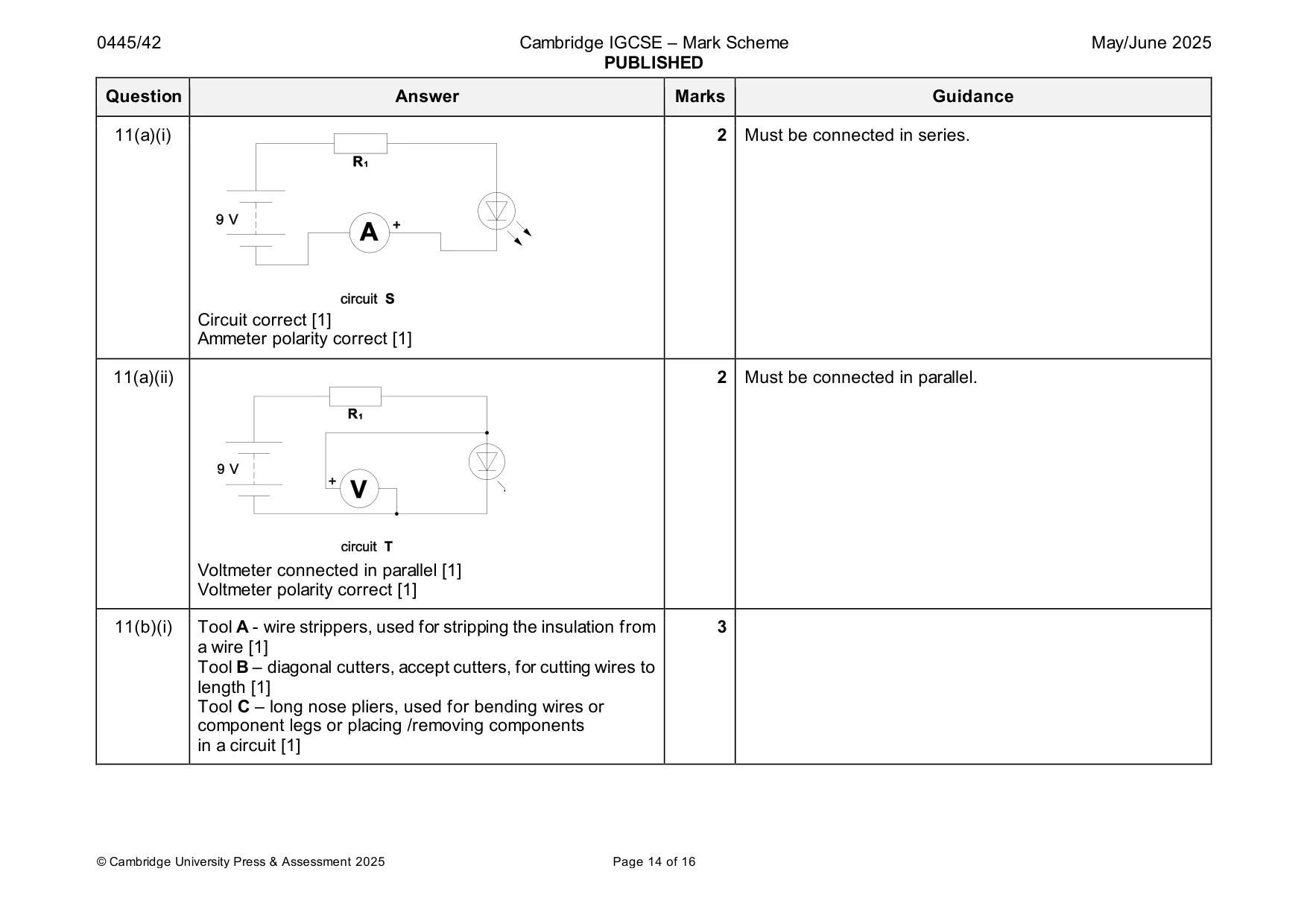
11 (a) Fig. 11.1 shows two incomplete light‑emitting diode (LED) circuits. R1 R1 9 V 9 V + + A V circuit S circuit T Fig. 11.1 (i) Complete circuit S to show how the current through the LED could be measured. [2] (ii) Complete circuit T to show how the voltage across the LED could be measured. [2] (b) Fig. 11.2 shows three tools used when constructing circuits. A B C Fig. 11.2 (i) State the purpose of each tool shown in Fig. 11.2. A ........................................................................................................................................ B ........................................................................................................................................ C ........................................................................................................................................ [3] (ii) Multicore solder contains flux which is incorporated in the solder. Give two reasons for incorporating flux in solder. 1 ........................................................................................................................................ 2 ........................................................................................................................................ [2] (iii) Use sketches and notes to show two connection methods used in circuit construction that do not involve soldering. [4] (c) Fig. 11.3 shows three capacitors. X Y Z Fig. 11.3 (i) Explain why care should be taken when fitting capacitors X and Y into a printed circuit board (PCB). ........................................................................................................................................... ........................................................................................................................................... ..................................................................................................................................... [2] (ii) State the result of connecting two capacitors in parallel. ..................................................................................................................................... [1]
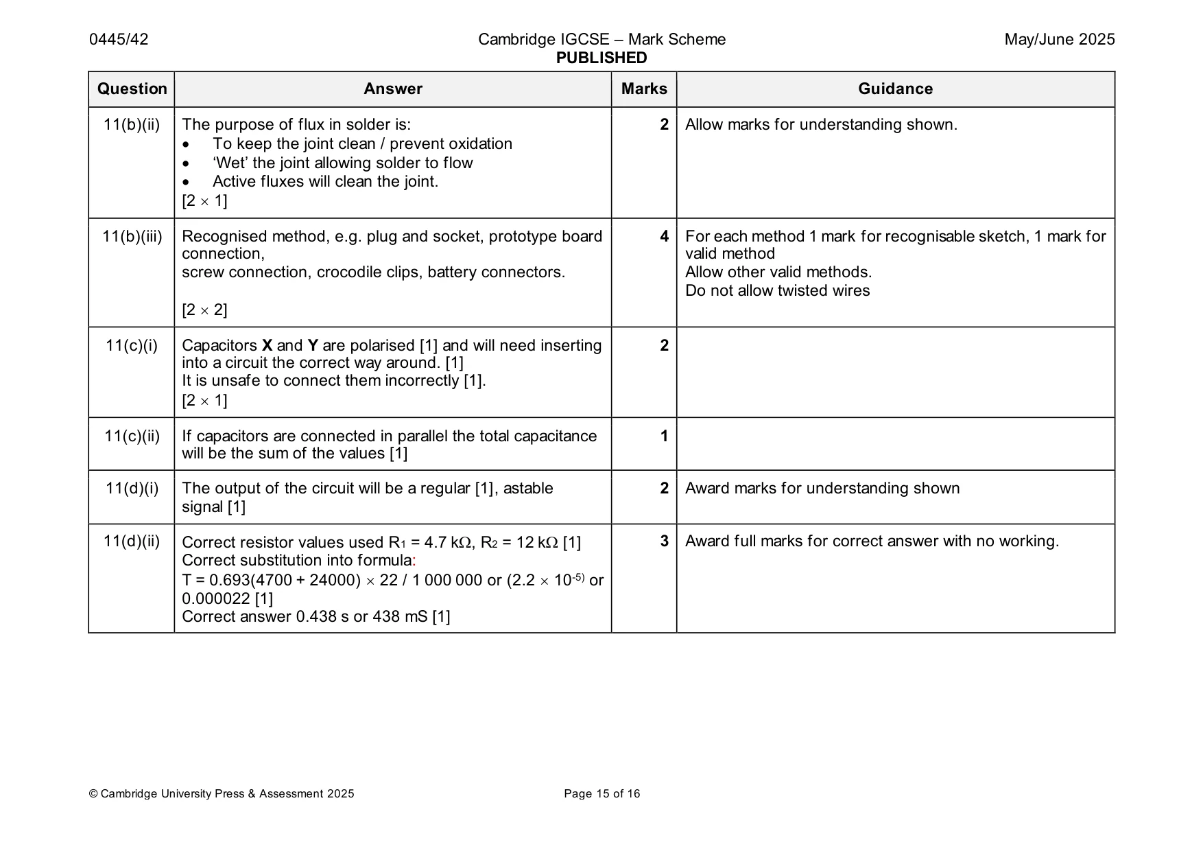
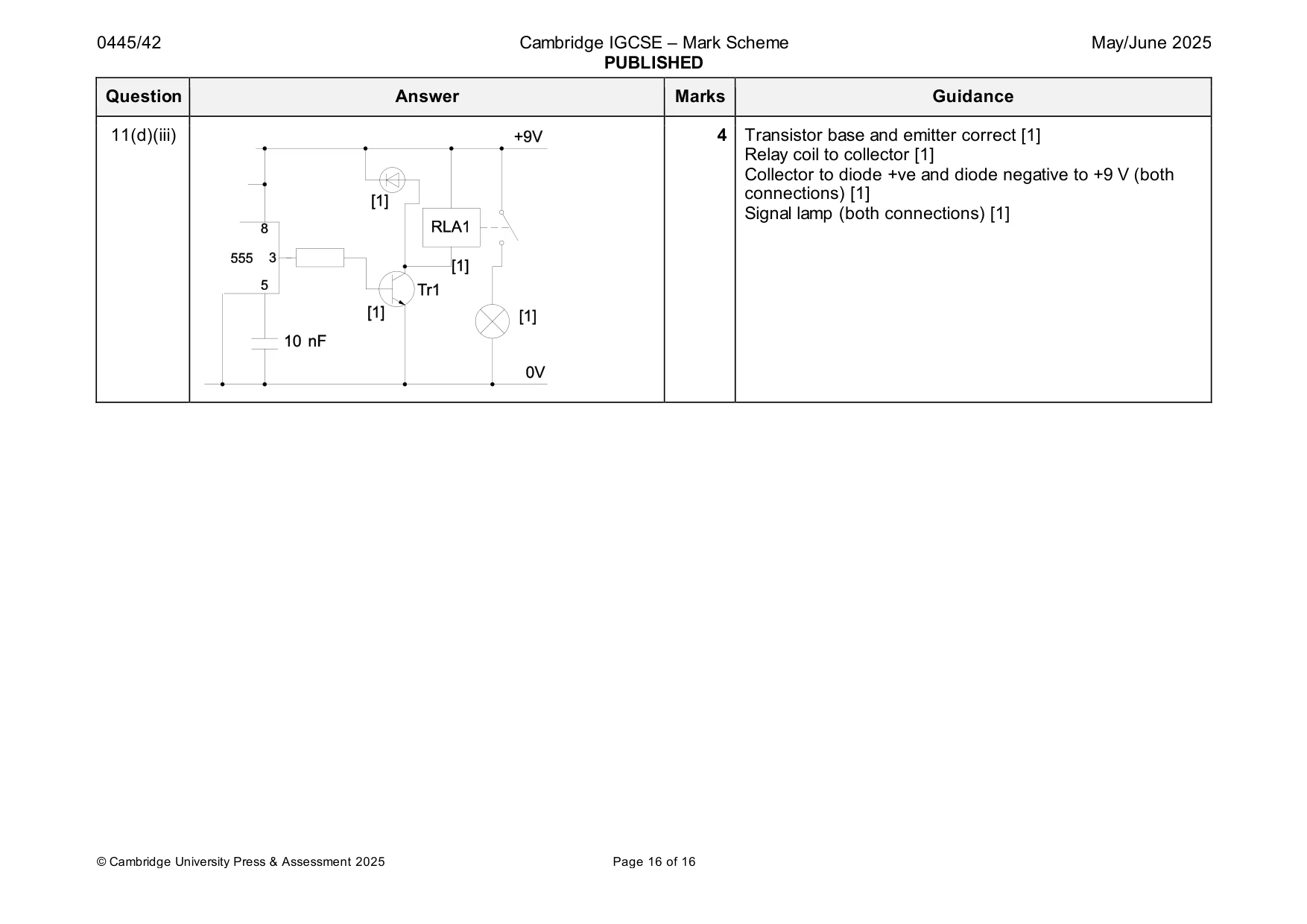
Mark scheme: 11(a)(i) 2 Must be connected in series. Circuit correct [1] Ammeter polarity correct [1] 11(a)(ii) 2 Must be connected in parallel. Voltmeter connected in parallel [1] Voltmeter polarity correct [1] 11(b)(i) Tool A - wire strippers, used for stripping the insulation from 3 a wire [1] Tool B – diagonal cutters, accept cutters, for cutting wires to length [1] Tool C – long nose pliers, used for bending wires or component legs or placing /removing components in a circuit [1] 11(b)(ii) The purpose of flux in solder is: 2 Allow marks for understanding shown. • To keep the joint clean / prevent oxidation • ‘Wet’ the joint allowing solder to flow • Active fluxes will clean the joint. [2 1] 11(b)(iii) Recognised method, e.g. plug and socket, prototype board 4 For each method 1 mark for recognisable sketch, 1 mark for connection, valid method screw connection, crocodile clips, battery connectors. Allow other valid methods. Do not allow twisted wires [2 2] 11(c)(i) Capacitors X and Y are polarised [1] and will need inserting 2 into a circuit the correct way around. [1] It is unsafe to connect them incorrectly [1]. [2 1] 11(c)(ii) If capacitors are connected in parallel the total capacitance 1 will be the sum of the values [1] 11(d)(i) The output of the circuit will be a regular [1], astable 2 Award marks for understanding shown signal [1] 11(d)(ii) Correct resistor values used R1 = 4.7 k, R2 = 12 k [1] 3 Award full marks for correct answer with no working. Correct substitution into formula: T = 0.693(4700 + 24000) 22 / 1 000 000 or (2.2 10-5) or 0.000022 [1] Correct answer 0.438 s or 438 mS [1] 11(d)(iii) 4 Transistor base and emitter correct [1] Relay coil to collector [1] Collector to diode +ve and diode negative to +9 V (both connections) [1] Signal lamp (both connections) [1]
What was in this paper
The subtopics covered by these 11 questions, and how many questions each got. Open one in a new tab to see every Cambridge question on it.
What you needed in this session
Cambridge’s own grade thresholds for 2025 May/June, Paper 4 · Variant 2. A higher threshold means an easier paper — the bar moves with how the cohort did.