Cambridge IGCSE Design and Technology 0445 — 2023 May/June Paper 4 · Variant 3
0445/43/M/J/23 · 12 questions · 50 marks · ≈56 min
The question paper and its mark scheme, free to read here and free to download. This is Cambridge’s own paper, exactly as it was sat.
Question paper20 pages


Mark scheme13 pages
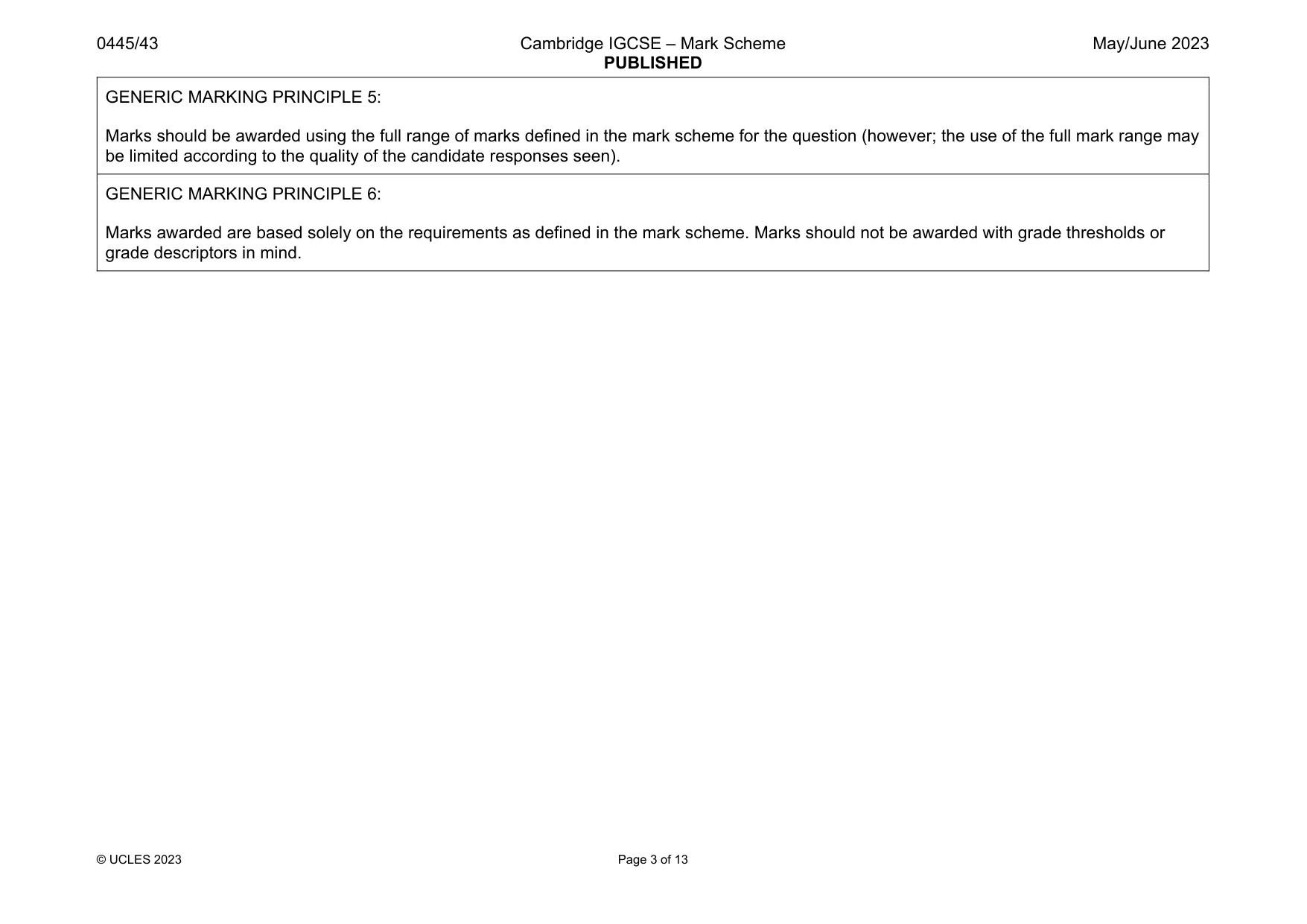
Answers below. Sit the paper first if you are practising.
Questions as text
Q1 · Name one example of each of the following natural structures
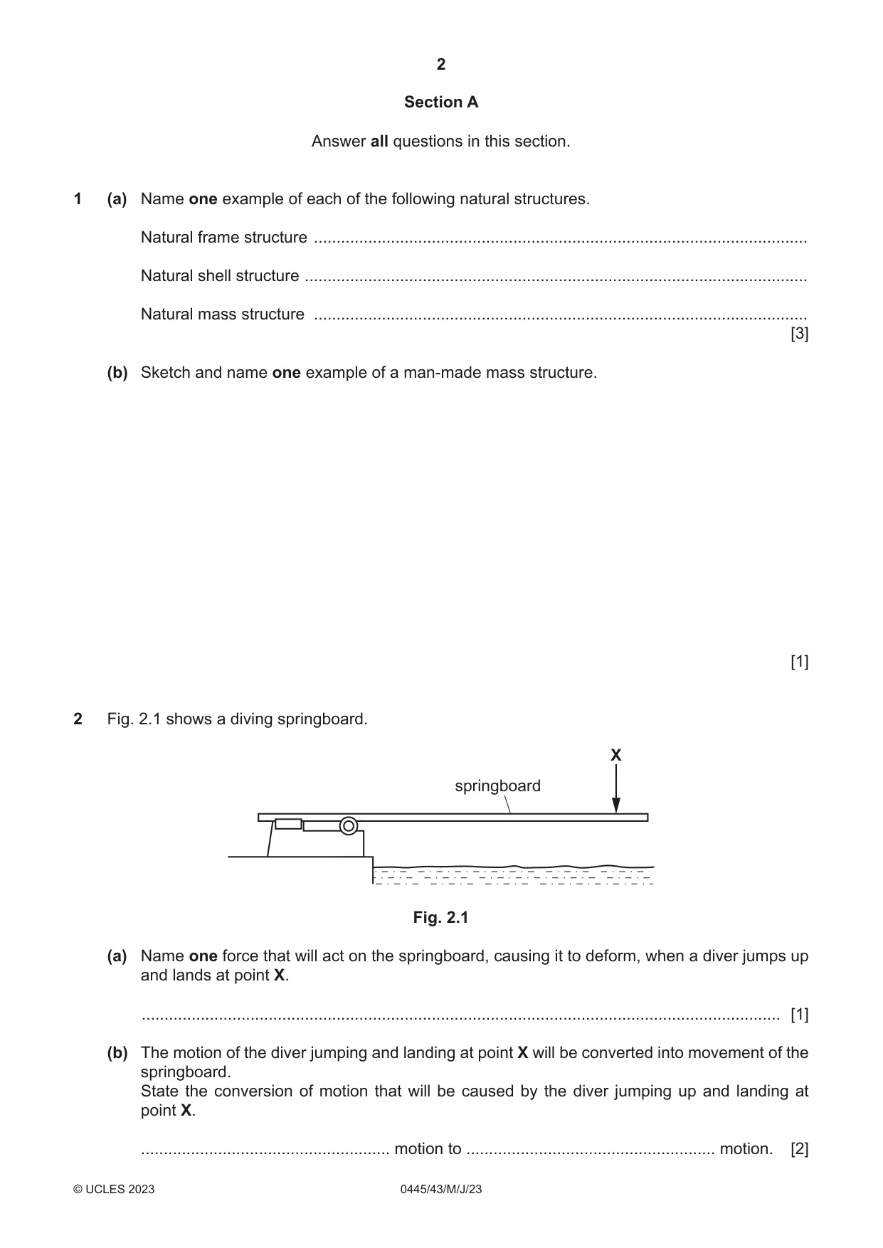
1 (a) Name one example of each of the following natural structures. Natural frame structure ............................................................................................................. Natural shell structure ............................................................................................................... Natural mass structure ............................................................................................................. [3] (b) Sketch and name one example of a man-made mass structure. [1]
Mark scheme: 1(a) Any recognisable natural frame structure [1] Any recognisable natural shell structure [1] Any recognisable natural mass structure [1] 3 Named structures must be natural. Accept ‘Bird’s nest’ as a frame structure Accept ‘Cave’ and ‘Tree trunk’ as mass 1(b) Any recognisable man-made mass structure [1] 1 If sketch is clearly recognisable without the name award mark
Question 2
2 Fig. 2.1 shows a diving springboard. X springboard Fig. 2.1 (a) Name one force that will act on the springboard, causing it to deform, when a diver jumps up and lands at point X. ............................................................................................................................................. [1] (b) The motion of the diver jumping and landing at point X will be converted into movement of the springboard. State the conversion of motion that will be caused by the diver jumping up and landing at point X. ....................................................... motion to ....................................................... motion. [2]
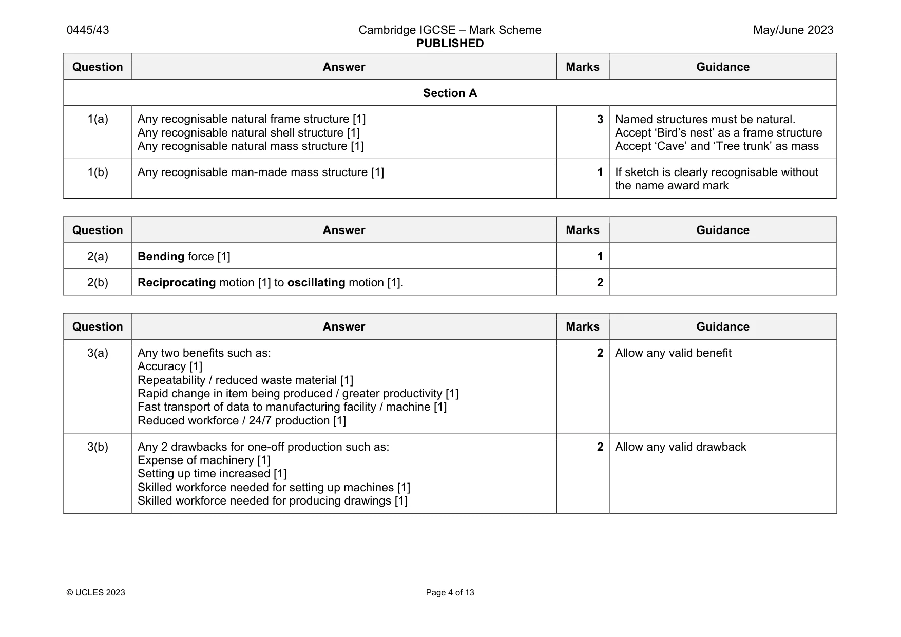
Mark scheme: 2(a) Bending force [1] 1 2(b) Reciprocating motion [1] to oscillating motion [1]. 2
Q3 · Give two benefits of using CAD/CAM in batch production
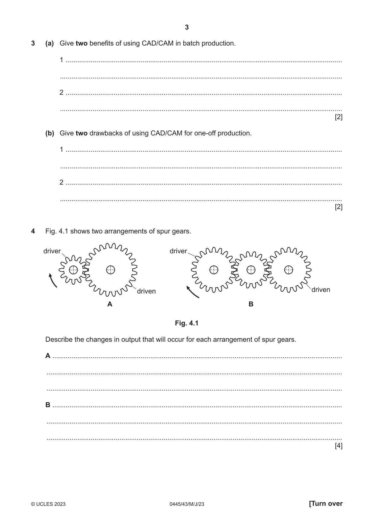
3 (a) Give two benefits of using CAD/CAM in batch production. 1 ................................................................................................................................................ ................................................................................................................................................... 2 ................................................................................................................................................ ................................................................................................................................................... [2] (b) Give two drawbacks of using CAD/CAM for one-off production. 1 ................................................................................................................................................ ................................................................................................................................................... 2 ................................................................................................................................................ ................................................................................................................................................... [2]
Mark scheme: 3(a) Any two benefits such as: Accuracy [1] Repeatability / reduced waste material [1] Rapid change in item being produced / greater productivity [1] Fast transport of data to manufacturing facility / machine [1] Reduced workforce / 24/7 production [1] 3(b) Any 2 drawbacks for one-off production such as: Expense of machinery [1] Setting up time increased [1] Skilled workforce needed for setting up machines [1] Skilled workforce needed for producing drawings [1] 2 Allow any valid drawback
Q4 · Two arrangements of spur gears
4 Fig. 4.1 shows two arrangements of spur gears. driver driver driven driven A B Fig. 4.1 Describe the changes in output that will occur for each arrangement of spur gears. A ....................................................................................................................................................... .......................................................................................................................................................... .......................................................................................................................................................... B ....................................................................................................................................................... .......................................................................................................................................................... .......................................................................................................................................................... [4]
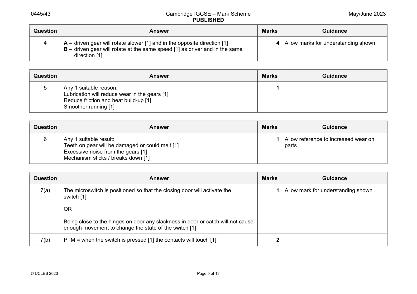
Mark scheme: 4 A – driven gear will rotate slower [1] and in the opposite direction [1] B – driven gear will rotate at the same speed [1] as driver and in the same direction [1] 4 Allow marks for understanding shown
Q5 · Give one reason for lubricating steel spur gears in a mechanism
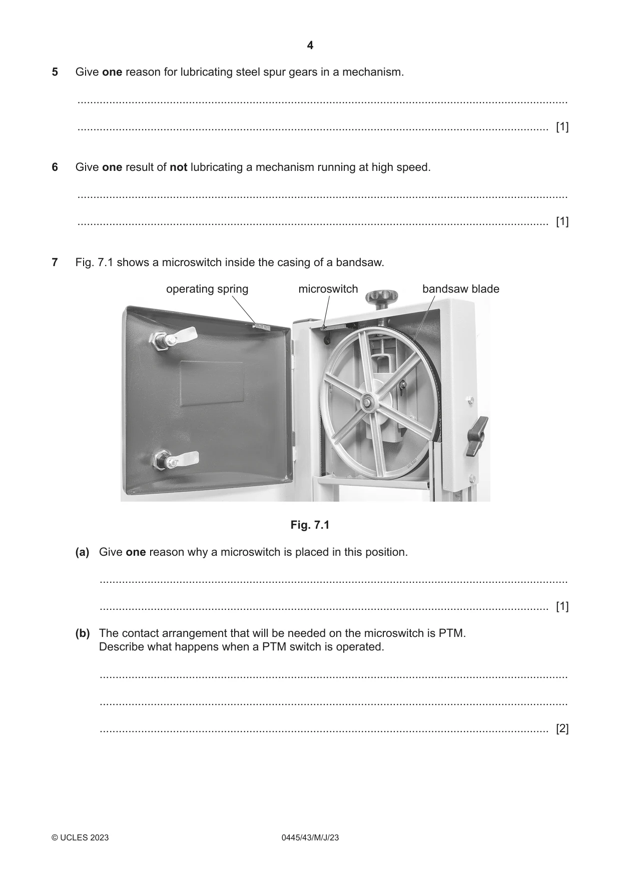
5 Give one reason for lubricating steel spur gears in a mechanism. .......................................................................................................................................................... .................................................................................................................................................... [1]
Mark scheme: 5 Any 1 suitable reason: Lubrication will reduce wear in the gears [1] Reduce friction and heat build-up [1] Smoother running [1] 1
Q6 · Give one result of not lubricating a mechanism running at high speed
6 Give one result of not lubricating a mechanism running at high speed. .......................................................................................................................................................... .................................................................................................................................................... [1]
Mark scheme: 6 Any 1 suitable result: Teeth on gear will be damaged or could melt [1] Excessive noise from the gears [1] Mechanism sticks / breaks down [1] 1 Allow reference to increased wear on parts
Q7 · A microswitch inside the casing of a bandsaw
7 Fig. 7.1 shows a microswitch inside the casing of a bandsaw. operating spring microswitch bandsaw blade Fig. 7.1 (a) Give one reason why a microswitch is placed in this position. ................................................................................................................................................... ............................................................................................................................................. [1] (b) The contact arrangement that will be needed on the microswitch is PTM. Describe what happens when a PTM switch is operated. ................................................................................................................................................... ................................................................................................................................................... ............................................................................................................................................. [2]
Mark scheme: 7(a) The microswitch is positioned so that the closing door will activate the switch [1] OR Being close to the hinges on door any slackness in door or catch will not cause enough movement to change the state of the switch [1] 7(b) PTM = when the switch is pressed [1] the contacts will touch [1] 2
Q8 · Two methods of connecting lamps in a circuit
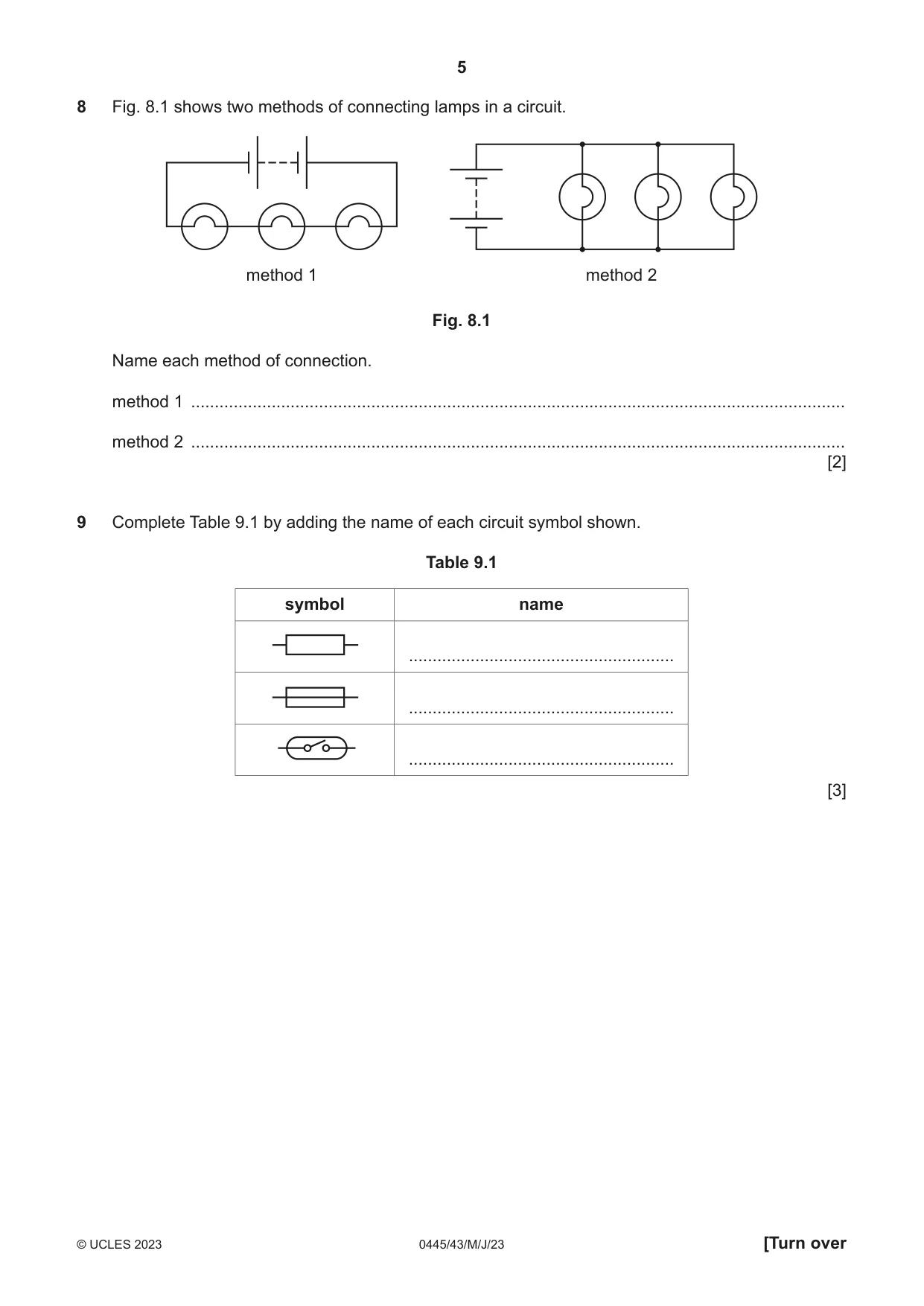
8 Fig. 8.1 shows two methods of connecting lamps in a circuit. method 1 method 2 Fig. 8.1 Name each method of connection. method 1 .......................................................................................................................................... method 2 .......................................................................................................................................... [2]
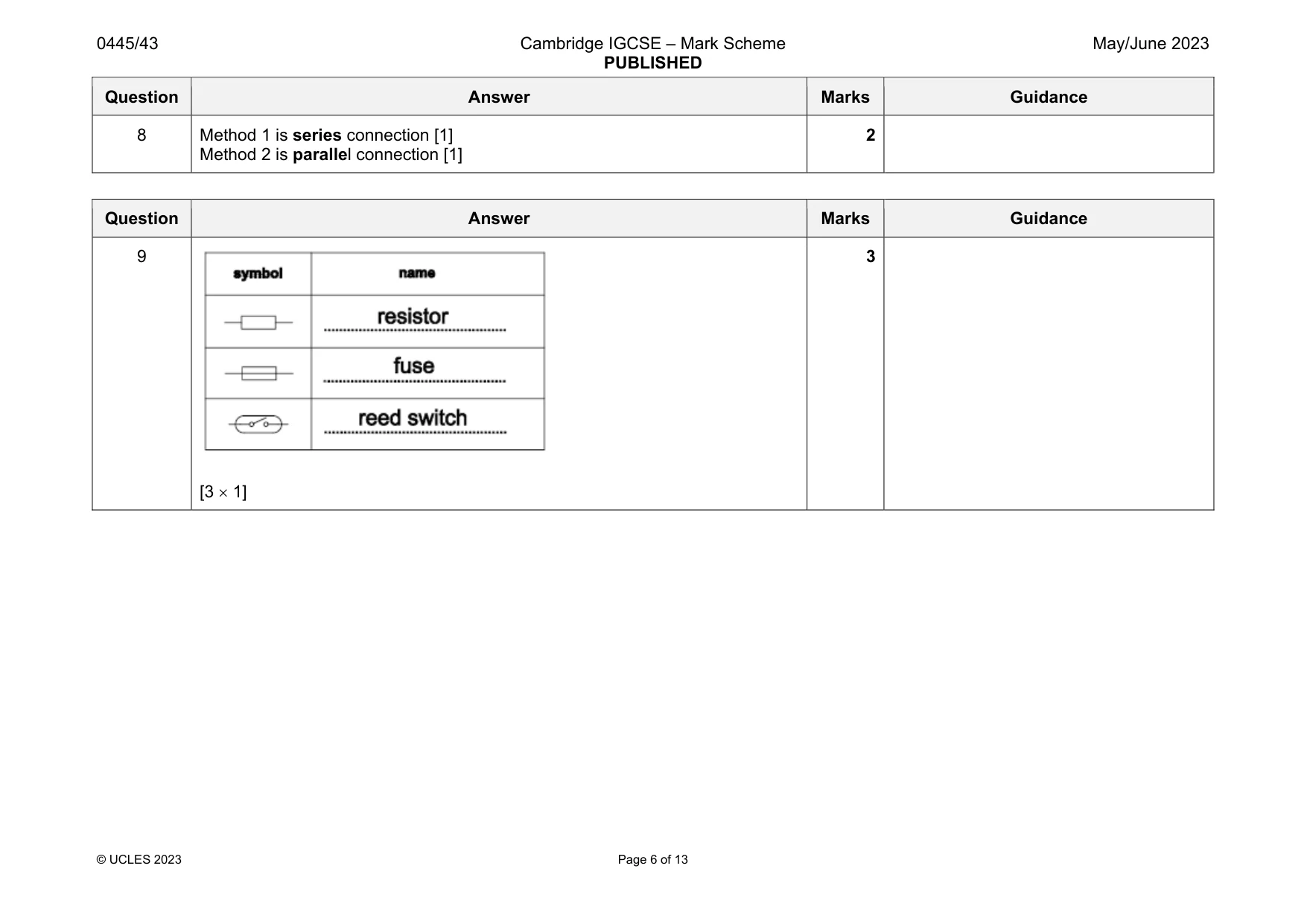
Mark scheme: 8 Method 1 is series connection [1] Method 2 is parallel connection [1] 2
Q9 · Complete Table 9.1 by adding the name of each circuit symbol shown
9 Complete Table 9.1 by adding the name of each circuit symbol shown. Table 9.1 symbol name ........................................................ ........................................................ ........................................................ [3]
Mark scheme: 9 [3 1]
Q10 · A concrete beam with two reinforcing rods running through it
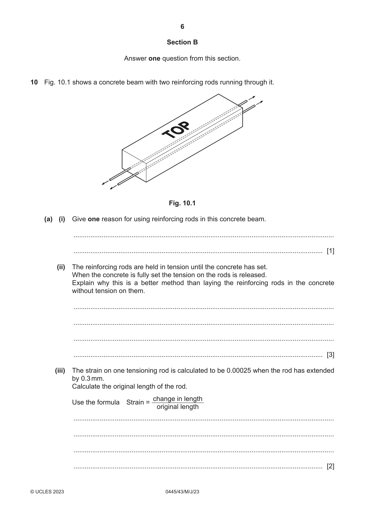
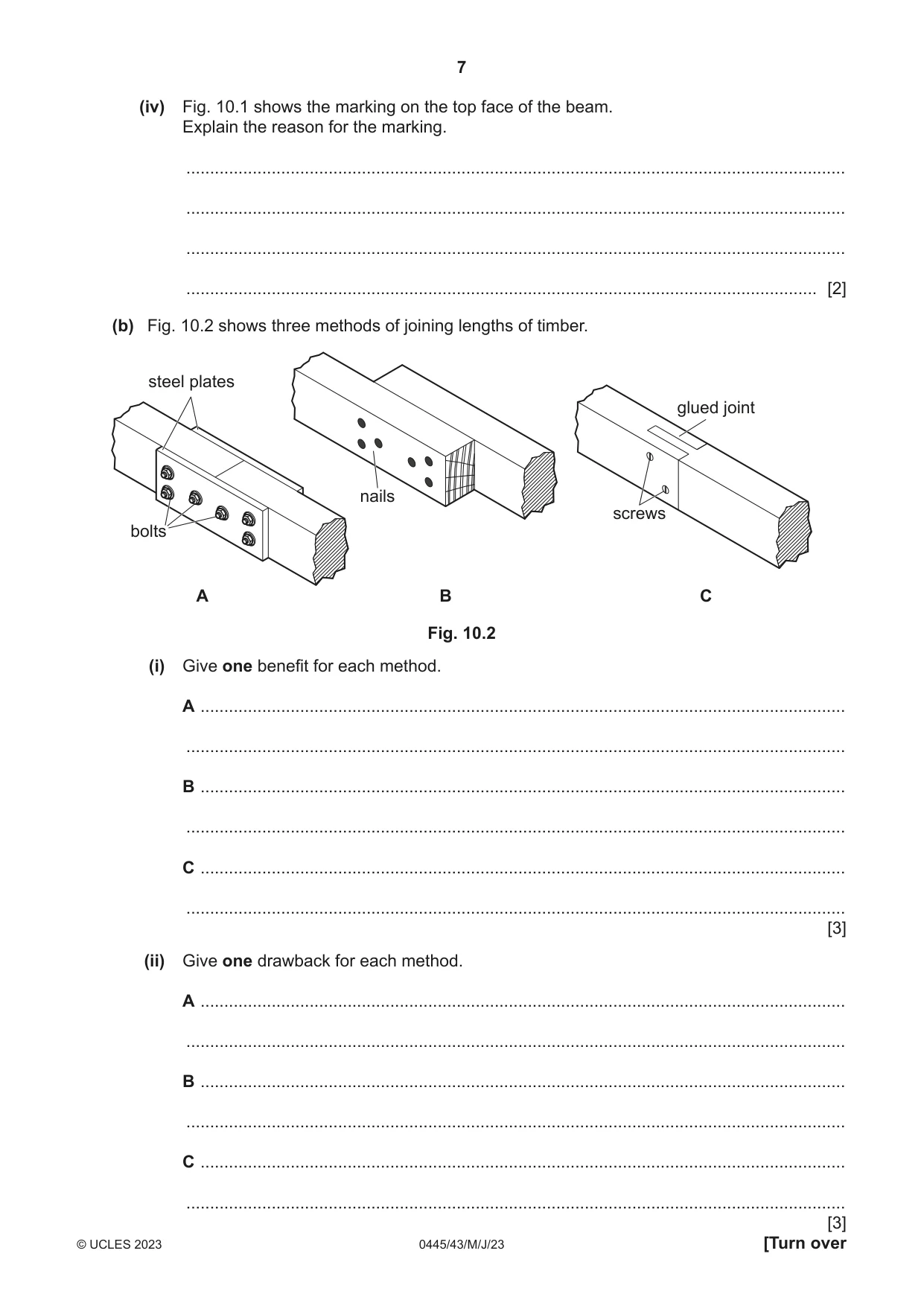
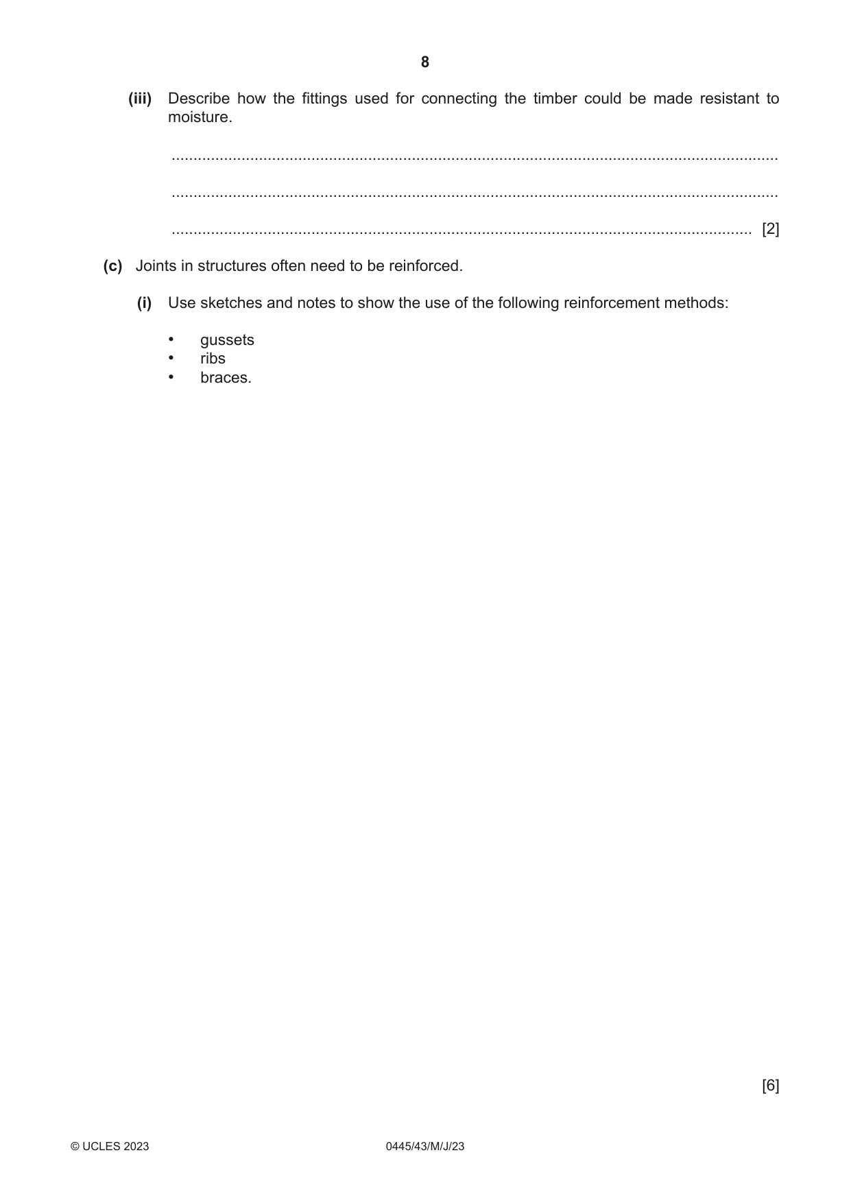
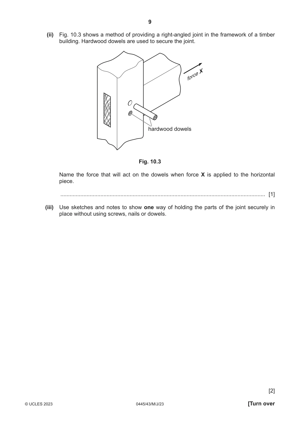
10 Fig. 10.1 shows a concrete beam with two reinforcing rods running through it. Fig. 10.1 (a) (i) Give one reason for using reinforcing rods in this concrete beam. ........................................................................................................................................... ..................................................................................................................................... [1] (ii) The reinforcing rods are held in tension until the concrete has set. When the concrete is fully set the tension on the rods is released. Explain why this is a better method than laying the reinforcing rods in the concrete without tension on them. ........................................................................................................................................... ........................................................................................................................................... ........................................................................................................................................... ..................................................................................................................................... [3] (iii) The strain on one tensioning rod is calculated to be 0.00025 when the rod has extended by 0.3 mm. Calculate the original length of the rod. change in length Use the formula Strain = original length ........................................................................................................................................... ........................................................................................................................................... ........................................................................................................................................... ..................................................................................................................................... [2] (iv) Fig. 10.1 shows the marking on the top face of the beam. Explain the reason for the marking. ........................................................................................................................................... ........................................................................................................................................... ........................................................................................................................................... ..................................................................................................................................... [2] (b) Fig. 10.2 shows three methods of joining lengths of timber. steel plates glued joint nails screws bolts A B C Fig. 10.2 (i) Give one benefit for each method. A ........................................................................................................................................ ........................................................................................................................................... B ........................................................................................................................................ ........................................................................................................................................... C ........................................................................................................................................ ........................................................................................................................................... [3] (ii) Give one drawback for each method. A ........................................................................................................................................ ........................................................................................................................................... B ........................................................................................................................................ ........................................................................................................................................... C ........................................................................................................................................ ........................................................................................................................................... (iii) Describe how the fittings used for connecting the timber could be made resistant to moisture. ........................................................................................................................................... ........................................................................................................................................... ..................................................................................................................................... [2] (c) Joints in structures often need to be reinforced. (i) Use sketches and notes to show the use of the following reinforcement methods: • gussets • ribs • braces. [6] (ii) Fig. 10.3 shows a method of providing a right-angled joint in the framework of a timber building. Hardwood dowels are used to secure the joint. X force hardwood dowels Fig. 10.3 Name the force that will act on the dowels when force X is applied to the horizontal piece. ..................................................................................................................................... [1] (iii) Use sketches and notes to show one way of holding the parts of the joint securely in place without using screws, nails or dowels. [2]
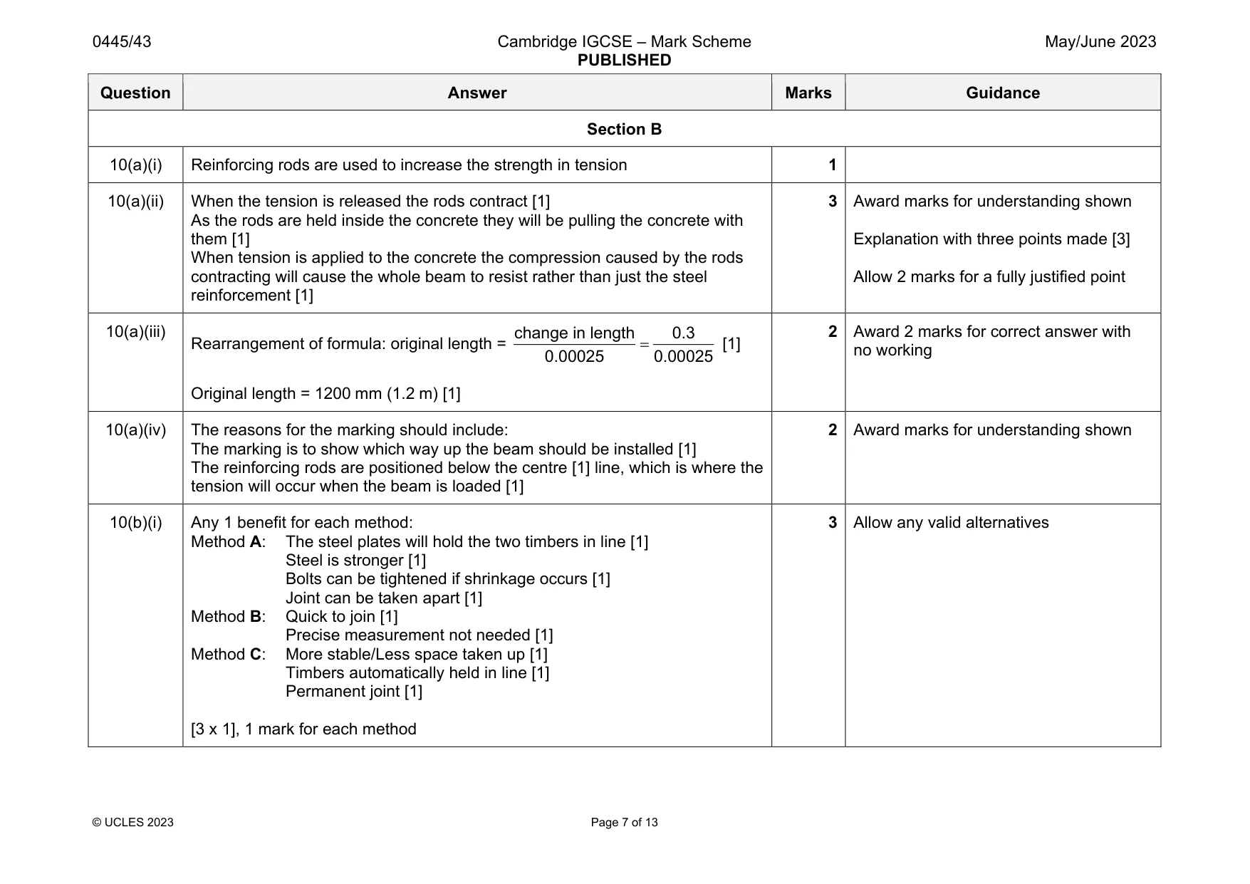
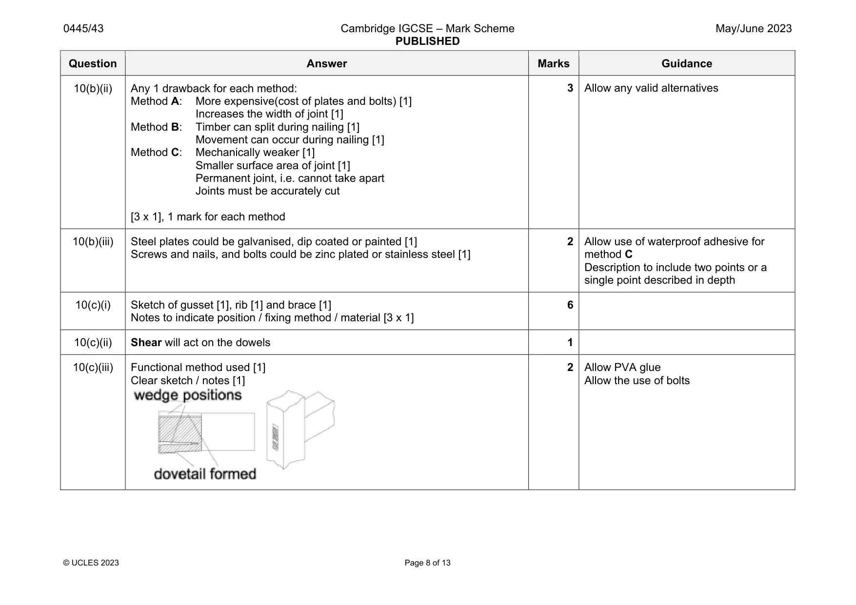
Mark scheme: 10(a)(i) Reinforcing rods are used to increase the strength in tension 1 10(a)(ii) When the tension is released the rods contract [1] As the rods are held inside the concrete they will be pulling the concrete with them [1] When tension is applied to the concrete the compression caused by the rods contracting will cause the whole beam to resist rather than just the steel reinforcement [1] 3 Award marks for understanding shown Explanation with three points made [3] Allow 2 marks for a fully justified point 10(a)(iii) Rearrangement of formula: original length = change in length 0.3 0.00025 0.00025 [1] Original length = 1200 mm (1.2 m) [1] 2 Award 2 marks for correct answer with no working 10(a)(iv) The reasons for the marking should include: The marking is to show which way up the beam should be installed [1] The reinforcing rods are positioned below the centre [1] line, which is where the tension will occur when the beam is loaded [1] 2 Award marks for understanding shown 10(b)(i) Any 1 benefit for each method: Method A: The steel plates will hold the two timbers in line [1] Steel is stronger [1] Bolts can be tightened if shrinkage occurs [1] Joint can be taken apart [1] Method B: Quick to join [1] Precise measurement not needed [1] Method C: More stable/Less space taken up [1] Timbers automatically held in line [1] Permanent joint [1] [3 x 1], 1 mark for each method 3 Allow any valid alternatives Question Answer Marks Guidance 10(b)(ii) Any 1 drawback for each method: Method A: More expensive(cost of plates and bolts) [1] Increases the width of joint [1] Method B: Timber can split during nailing [1] Movement can occur during nailing [1] Method C: Mechanically weaker [1] Smaller surface area of joint [1] Permanent joint, i.e. cannot take apart Joints must be accurately cut [3 x 1], 1 mark for each method 3 Allow any valid alternatives 10(b)(iii) Steel plates could be galvanised, dip coated or painted [1] Screws and nails, and bolts could be zinc plated or stainless steel [1] 2 Allow use of waterproof adhesive for method C Description to include two points or a single point described in depth 10(c)(i) Sketch of gusset [1], rib [1] and brace [1] Notes to indicate position / fixing method / material [3 x 1] 6 10(c)(ii) Shear will act on the dowels 1 10(c)(iii) Functional method used [1] Clear sketch / notes [1] 2 Allow PVA glue Allow the use of bolts
Q11 · A water spray bottle operated by finger pressure on the operating lever
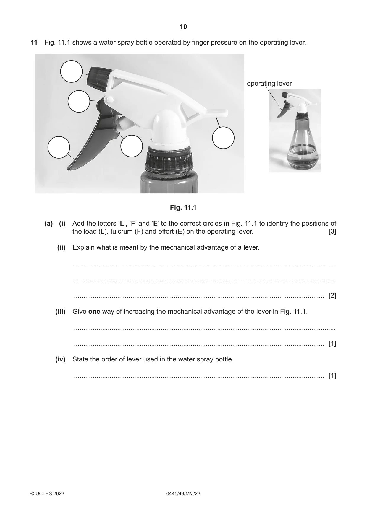
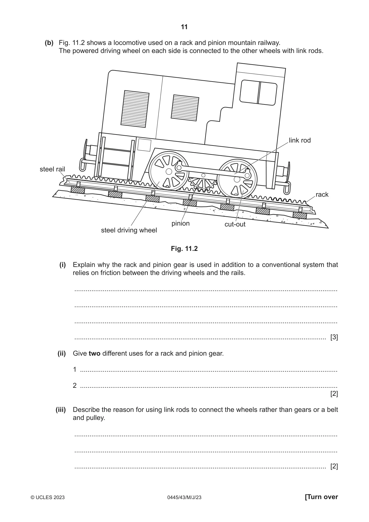
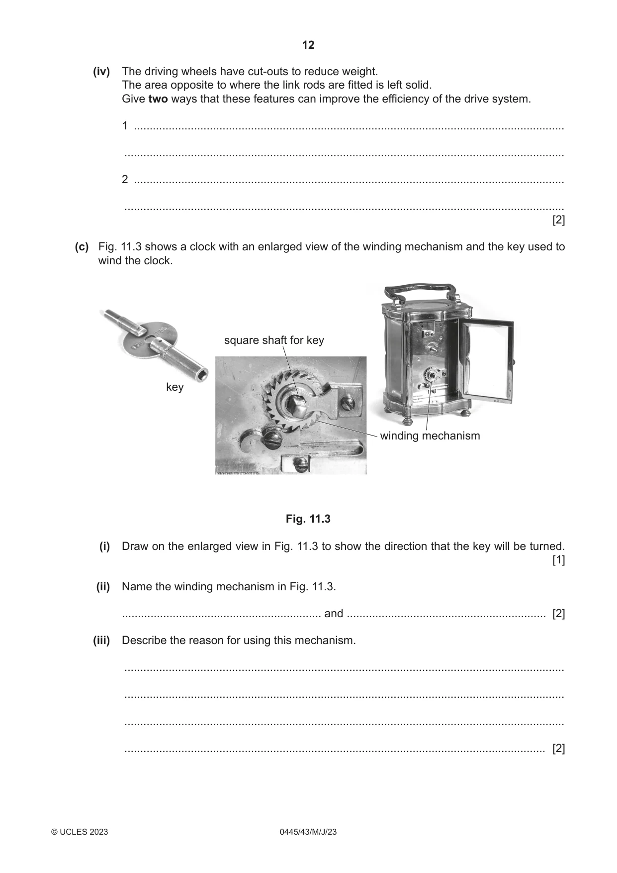
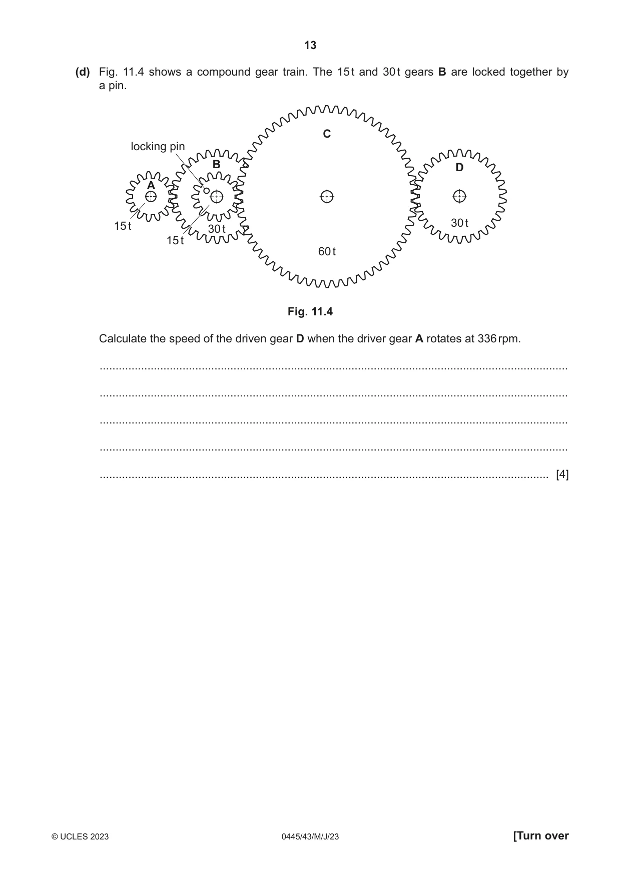
11 Fig. 11.1 shows a water spray bottle operated by finger pressure on the operating lever. operating lever Fig. 11.1 (a) (i) Add the letters ‘L’, ‘F’ and ‘E’ to the correct circles in Fig. 11.1 to identify the positions of the load (L), fulcrum (F) and effort (E) on the operating lever. [3] (ii) Explain what is meant by the mechanical advantage of a lever. ........................................................................................................................................... ........................................................................................................................................... ..................................................................................................................................... [2] (iii) Give one way of increasing the mechanical advantage of the lever in Fig. 11.1. ........................................................................................................................................... ..................................................................................................................................... [1] (iv) State the order of lever used in the water spray bottle. ..................................................................................................................................... [1] (b) Fig. 11.2 shows a locomotive used on a rack and pinion mountain railway. The powered driving wheel on each side is connected to the other wheels with link rods. link rod steel rail rack pinion cut-out steel driving wheel Fig. 11.2 (i) Explain why the rack and pinion gear is used in addition to a conventional system that relies on friction between the driving wheels and the rails. ........................................................................................................................................... ........................................................................................................................................... ........................................................................................................................................... ..................................................................................................................................... [3] (ii) Give two different uses for a rack and pinion gear. 1 ........................................................................................................................................ 2 ........................................................................................................................................ [2] (iii) Describe the reason for using link rods to connect the wheels rather than gears or a belt and pulley. ........................................................................................................................................... ........................................................................................................................................... ..................................................................................................................................... [2] (iv) The driving wheels have cut-outs to reduce weight. The area opposite to where the link rods are fitted is left solid. Give two ways that these features can improve the efficiency of the drive system. 1 ........................................................................................................................................ ........................................................................................................................................... 2 ........................................................................................................................................ ........................................................................................................................................... [2] (c) Fig. 11.3 shows a clock with an enlarged view of the winding mechanism and the key used to wind the clock. square shaft for key key winding mechanism Fig. 11.3 (i) Draw on the enlarged view in Fig. 11.3 to show the direction that the key will be turned. [1] (ii) Name the winding mechanism in Fig. 11.3. ............................................................... and ............................................................... [2] (iii) Describe the reason for using this mechanism. ........................................................................................................................................... ........................................................................................................................................... ........................................................................................................................................... ..................................................................................................................................... [2] (d) Fig. 11.4 shows a compound gear train. The 15 t and 30 t gears B are locked together by a pin. C locking pin B D A 15 t 30 t 30 t 15 t 60 t Fig. 11.4 Calculate the speed of the driven gear D when the driver gear A rotates at 336 rpm. ................................................................................................................................................... ................................................................................................................................................... ................................................................................................................................................... ................................................................................................................................................... ............................................................................................................................................. [4]
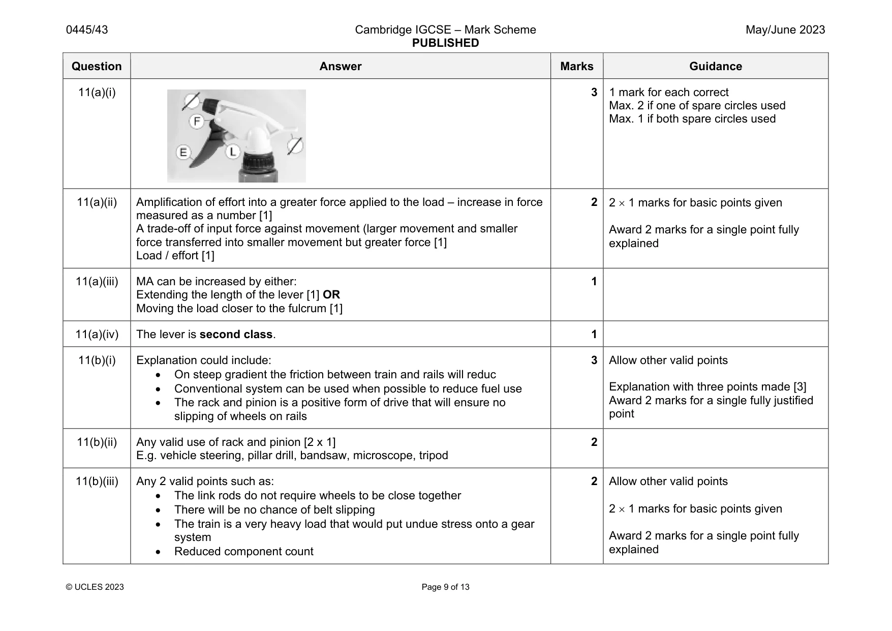
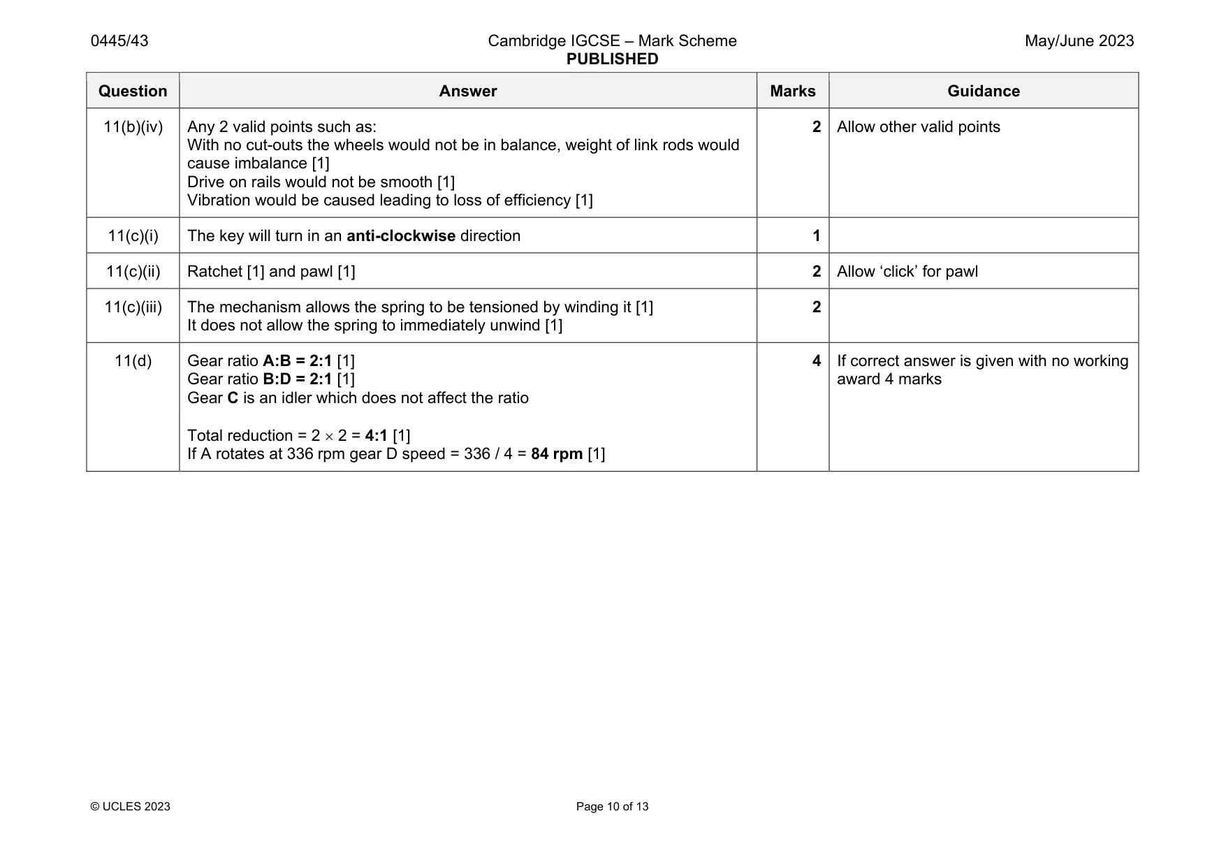
Mark scheme: 11(a)(i) 3 1 mark for each correct Max. 2 if one of spare circles used Max. 1 if both spare circles used 11(a)(ii) Amplification of effort into a greater force applied to the load – increase in force measured as a number [1] A trade-off of input force against movement (larger movement and smaller force transferred into smaller movement but greater force [1] Load / effort [1] 2 2 1 marks for basic points given Award 2 marks for a single point fully explained 11(a)(iii) MA can be increased by either: Extending the length of the lever [1] OR Moving the load closer to the fulcrum [1] 1 11(a)(iv) The lever is second class. 1 11(b)(i) Explanation could include: On steep gradient the friction between train and rails will reduc Conventional system can be used when possible to reduce fuel use The rack and pinion is a positive form of drive that will ensure no slipping of wheels on rails 3 Allow other valid points Explanation with three points made [3] Award 2 marks for a single fully justified point 11(b)(ii) Any valid use of rack and pinion [2 x 1] E.g. vehicle steering, pillar drill, bandsaw, microscope, tripod 2 11(b)(iii) Any 2 valid points such as: The link rods do not require wheels to be close together There will be no chance of belt slipping The train is a very heavy load that would put undue stress onto a gear system Reduced component count 2 Allow other valid points 2 1 marks for basic points given Award 2 marks for a single point fully explained Question Answer Marks Guidance 11(b)(iv) Any 2 valid points such as: With no cut-outs the wheels would not be in balance, weight of link rods would cause imbalance [1] Drive on rails would not be smooth [1] Vibration would be caused leading to loss of efficiency [1] 2 Allow other valid points 11(c)(i) The key will turn in an anti-clockwise direction 1 11(c)(ii) Ratchet [1] and pawl [1] 2 Allow ‘click’ for pawl 11(c)(iii) The mechanism allows the spring to be tensioned by winding it [1] It does not allow the spring to immediately unwind [1] 2 11(d) Gear ratio A:B = 2:1 [1] Gear ratio B:D = 2:1 [1] Gear C is an idler which does not affect the ratio Total reduction = 2 2 = 4:1 [1] If A rotates at 336 rpm gear D speed = 336 / 4 = 84 rpm [1] 4 If correct answer is given with no working award 4 marks
Q12 · Three methods of making connections to an electronic circuit
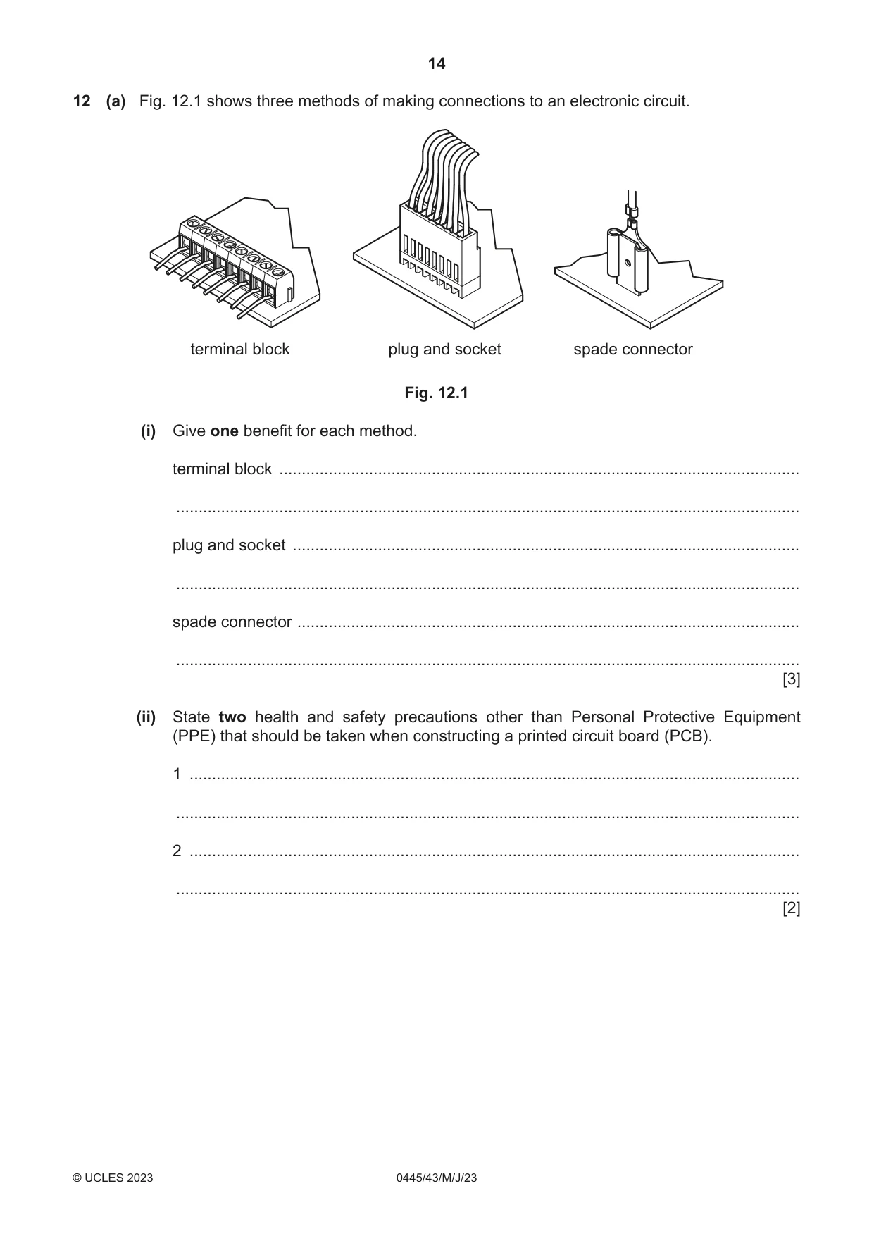
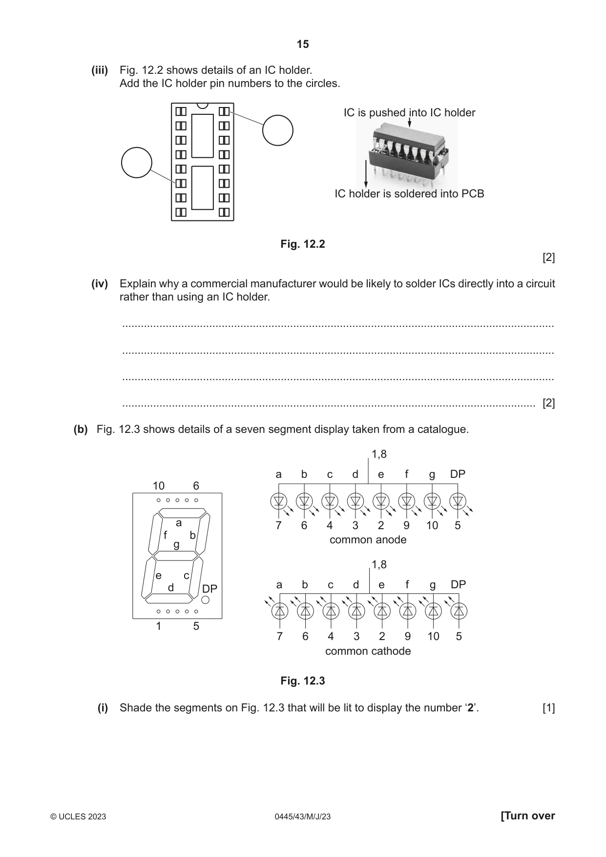
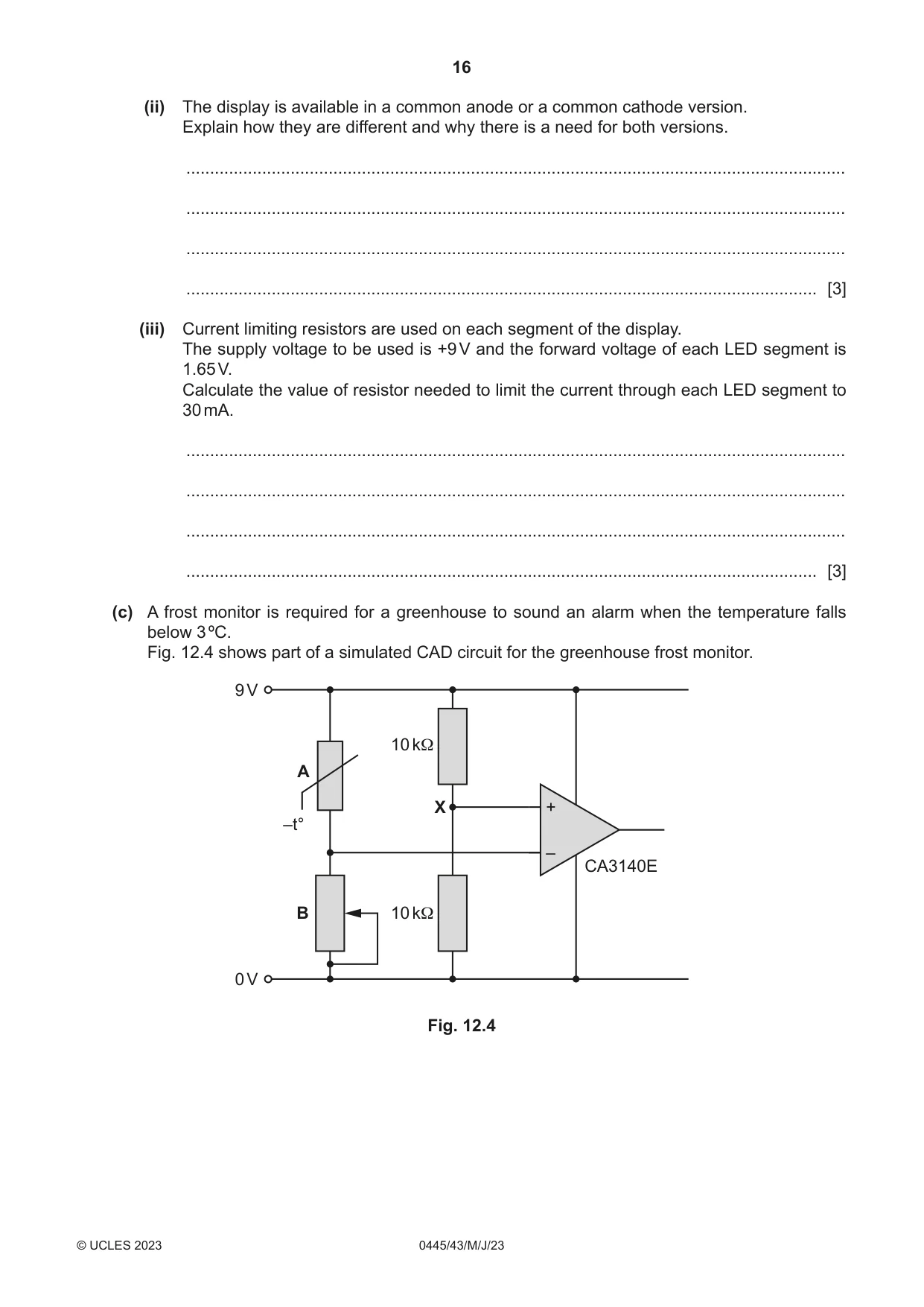
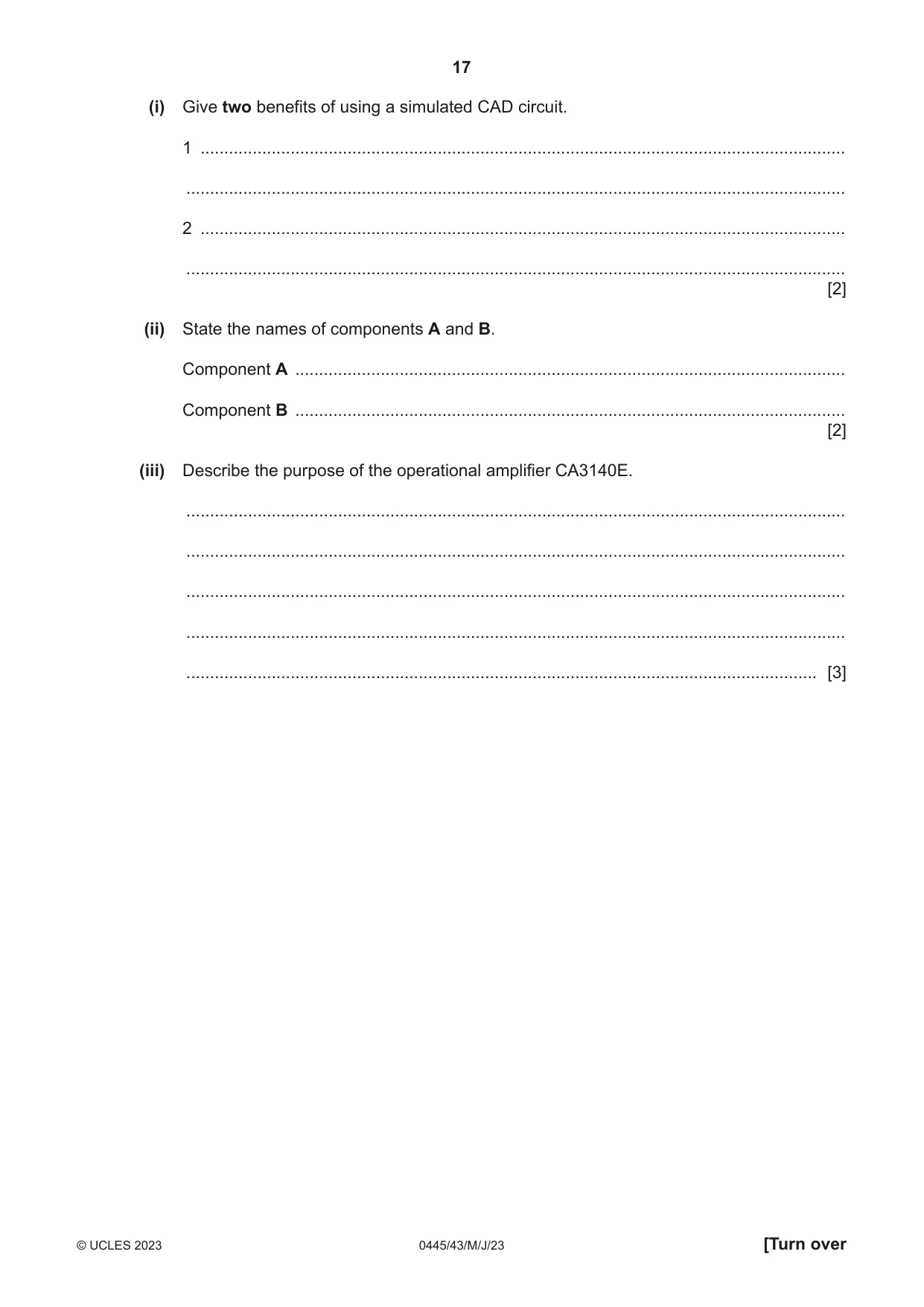
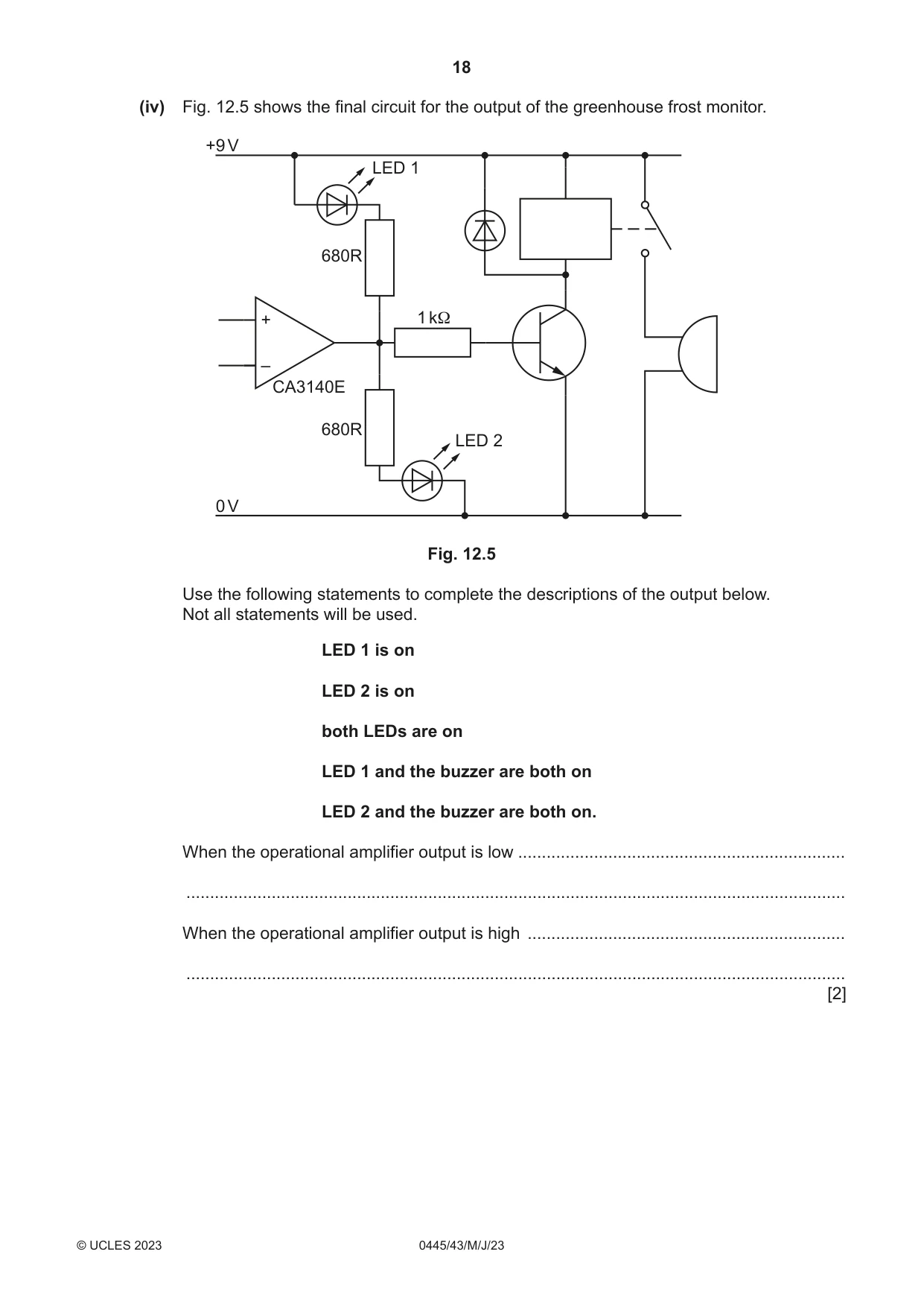
12 (a) Fig. 12.1 shows three methods of making connections to an electronic circuit. terminal block plug and socket spade connector Fig. 12.1 (i) Give one benefit for each method. terminal block .................................................................................................................... ........................................................................................................................................... plug and socket ................................................................................................................. ........................................................................................................................................... spade connector ................................................................................................................ ........................................................................................................................................... [3] (ii) State two health and safety precautions other than Personal Protective Equipment (PPE) that should be taken when constructing a printed circuit board (PCB). 1 ........................................................................................................................................ ........................................................................................................................................... 2 ........................................................................................................................................ ........................................................................................................................................... [2] (iii) Fig. 12.2 shows details of an IC holder. Add the IC holder pin numbers to the circles. IC is pushed into IC holder IC holder is soldered into PCB Fig. 12.2 [2] (iv) Explain why a commercial manufacturer would be likely to solder ICs directly into a circuit rather than using an IC holder. ........................................................................................................................................... ........................................................................................................................................... ........................................................................................................................................... ..................................................................................................................................... [2] (b) Fig. 12.3 shows details of a seven segment display taken from a catalogue. 1,8 a b c d e f g DP 10 6 a 7 6 4 3 2 9 10 5 f b common anode g 1,8 e c a b c d e f g DP d DP 1 5 7 6 4 3 2 9 10 5 common cathode Fig. 12.3 (i) Shade the segments on Fig. 12.3 that will be lit to display the number ‘2’. [1] (ii) The display is available in a common anode or a common cathode version. Explain how they are different and why there is a need for both versions. ........................................................................................................................................... ........................................................................................................................................... ........................................................................................................................................... ..................................................................................................................................... [3] (iii) Current limiting resistors are used on each segment of the display. The supply voltage to be used is +9 V and the forward voltage of each LED segment is 1.65 V. Calculate the value of resistor needed to limit the current through each LED segment to 30 mA. ........................................................................................................................................... ........................................................................................................................................... ........................................................................................................................................... ..................................................................................................................................... [3] (c) A frost monitor is required for a greenhouse to sound an alarm when the temperature falls below 3 ºC. Fig. 12.4 shows part of a simulated CAD circuit for the greenhouse frost monitor. 9 V 10 kΩ A X + –t° – CA3140E B 10 kΩ 0 V Fig. 12.4
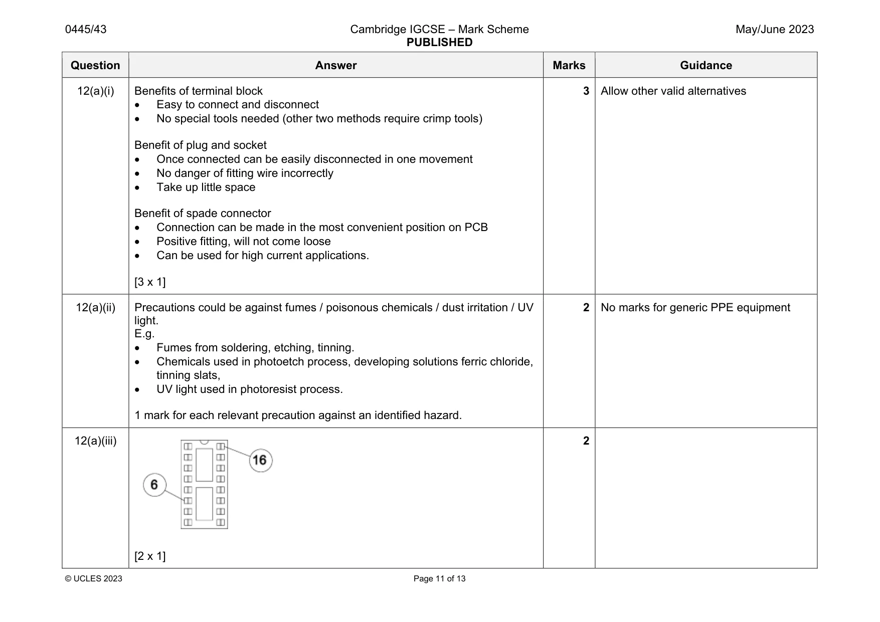
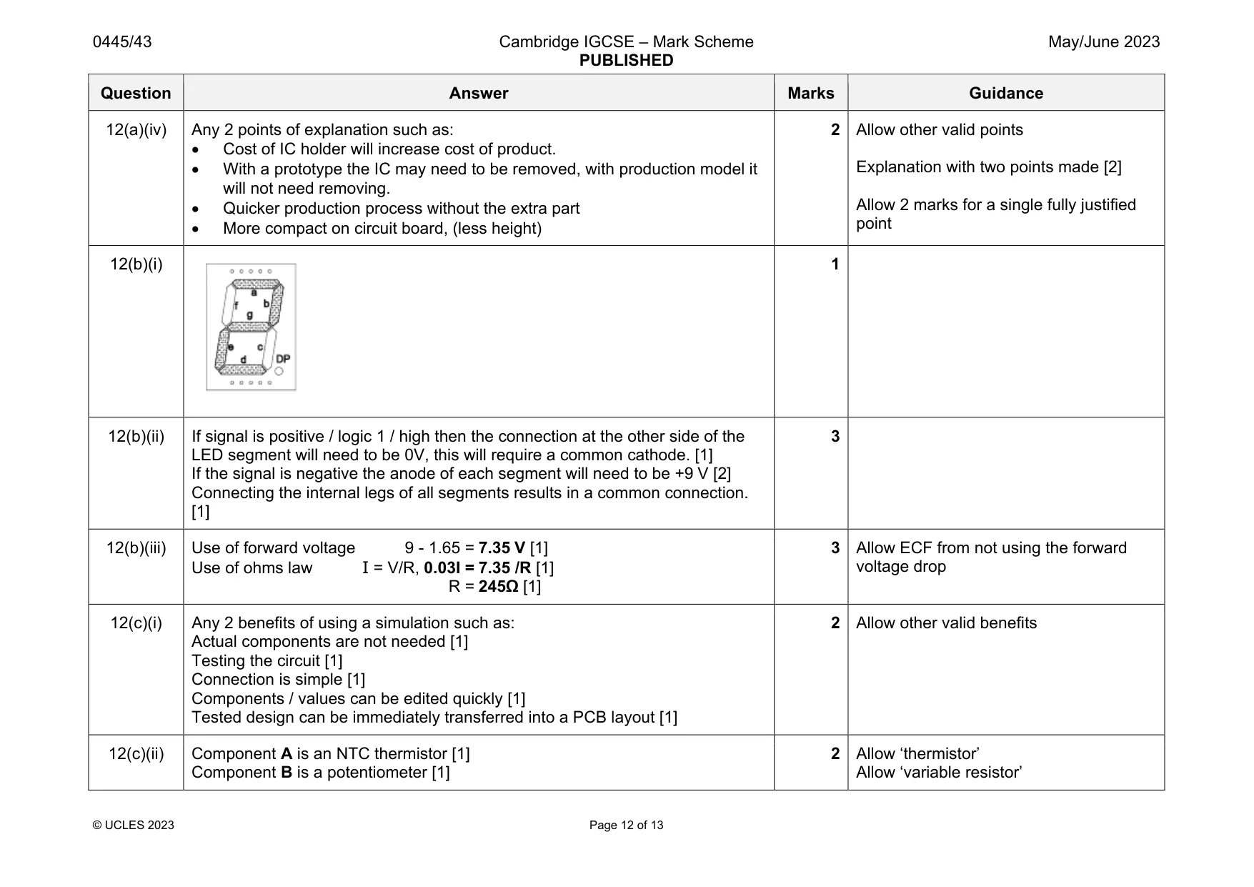
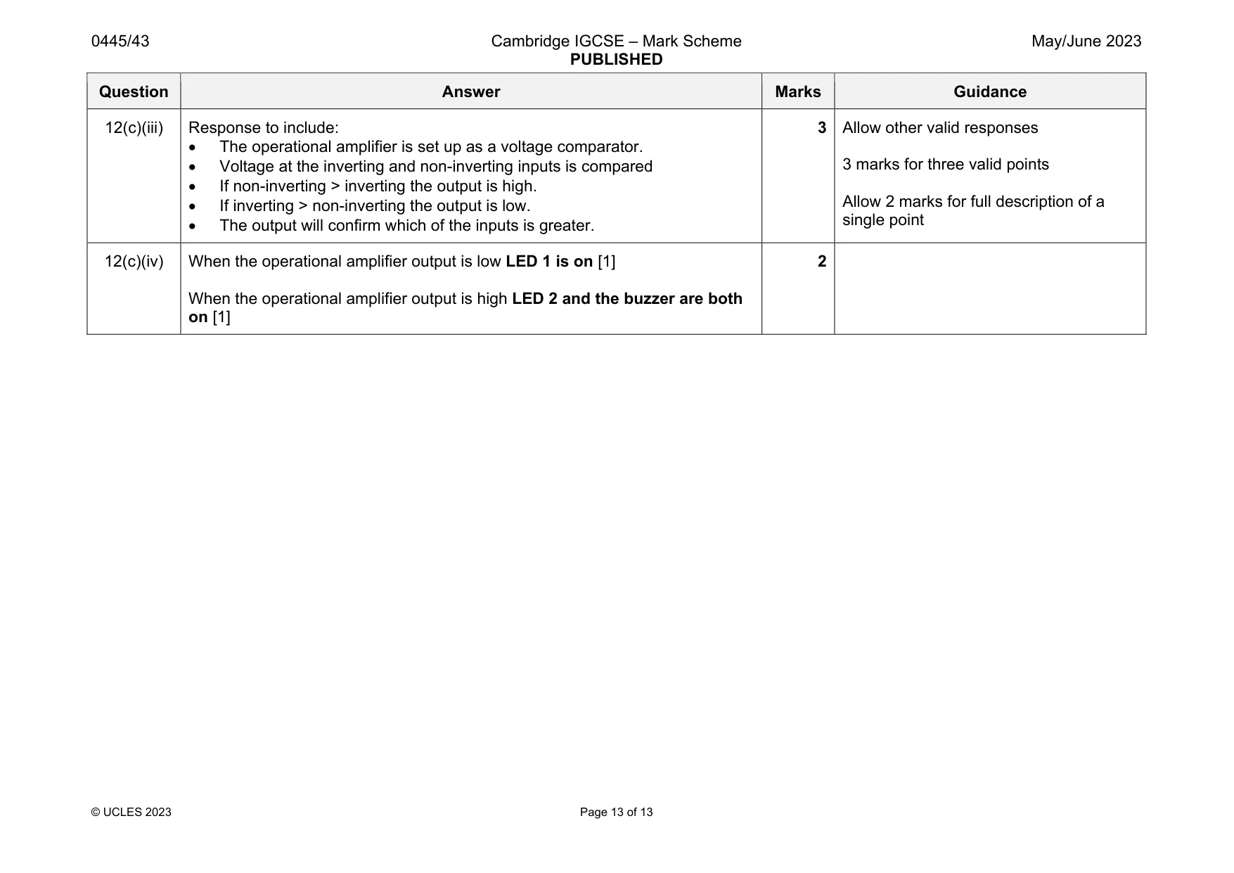
Mark scheme: 12(a)(i) Benefits of terminal block Easy to connect and disconnect No special tools needed (other two methods require crimp tools) Benefit of plug and socket Once connected can be easily disconnected in one movement No danger of fitting wire incorrectly Take up little space Benefit of spade connector Connection can be made in the most convenient position on PCB Positive fitting, will not come loose Can be used for high current applications. [3 x 1] 3 Allow other valid alternatives 12(a)(ii) Precautions could be against fumes / poisonous chemicals / dust irritation / UV light. E.g. Fumes from soldering, etching, tinning. Chemicals used in photoetch process, developing solutions ferric chloride, tinning slats, UV light used in photoresist process. 1 mark for each relevant precaution against an identified hazard. 2 No marks for generic PPE equipment 12(a)(iii) [2 x 1] 2 Question Answer Marks Guidance 12(a)(iv) Any 2 points of explanation such as: Cost of IC holder will increase cost of product. With a prototype the IC may need to be removed, with production model it will not need removing. Quicker production process without the extra part More compact on circuit board, (less height) 2 Allow other valid points Explanation with two points made [2] Allow 2 marks for a single fully justified point 12(b)(i) 1 12(b)(ii) If signal is positive / logic 1 / high then the connection at the other side of the LED segment will need to be 0V, this will require a common cathode. [1] If the signal is negative the anode of each segment will need to be +9 V [2] Connecting the internal legs of all segments results in a common connection. [1] 3 12(b)(iii) Use of forward voltage 9 - 1.65 = 7.35 V [1] Use of ohms law I = V/R, 0.03I = 7.35 /R [1] R = 245Ω [1] 3 Allow ECF from not using the forward voltage drop 12(c)(i) Any 2 benefits of using a simulation such as: Actual components are not needed [1] Testing the circuit [1] Connection is simple [1] Components / values can be edited quickly [1] Tested design can be immediately transferred into a PCB layout [1] 2 Allow other valid benefits 12(c)(ii) Component A is an NTC thermistor [1] Component B is a potentiometer [1] 2 Allow ‘thermistor’ Allow ‘variable resistor’ Question Answer Marks Guidance 12(c)(iii) Response to include: The operational amplifier is set up as a voltage comparator. Voltage at the inverting and non-inverting inputs is compared If non-inverting > inverting the output is high. If inverting > non-inverting the output is low. The output will confirm which of the inputs is greater. 3 Allow other valid responses 3 marks for three valid points Allow 2 marks for full description of a single point 12(c)(iv) When the operational amplifier output is low LED 1 is on [1] When the operational amplifier output is high LED 2 and the buzzer are both on [1] 2
What was in this paper
The subtopics covered by these 12 questions, and how many questions each got. Open one in a new tab to see every Cambridge question on it.
What you needed in this session
Cambridge’s own grade thresholds for 2023 May/June, Paper 4 · Variant 3. A higher threshold means an easier paper — the bar moves with how the cohort did.