Cambridge IGCSE Design and Technology 0445 — 2023 May/June Paper 4 · Variant 2
0445/42/M/J/23 · 12 questions · 50 marks · ≈56 min
The question paper and its mark scheme, free to read here and free to download. This is Cambridge’s own paper, exactly as it was sat.
Question paper20 pages



Mark scheme13 pages
Answers below. Sit the paper first if you are practising.

Questions as text
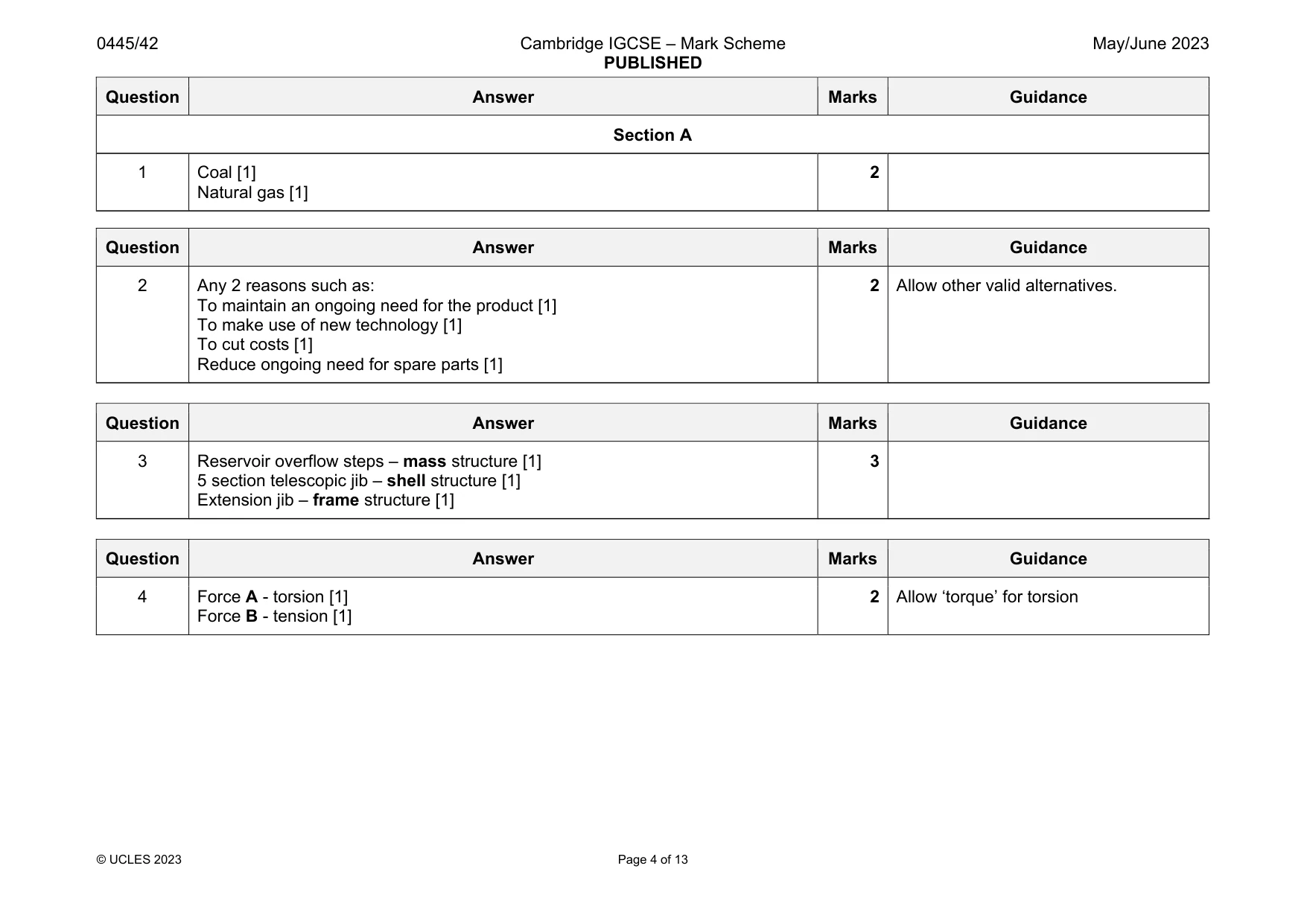
Q1 · Identify two fossil fuels from the list below
1 Identify two fossil fuels from the list below. coal geothermal hydroelectric natural gas solar 1 ....................................................................................................................................................... 2 ....................................................................................................................................................... [2]
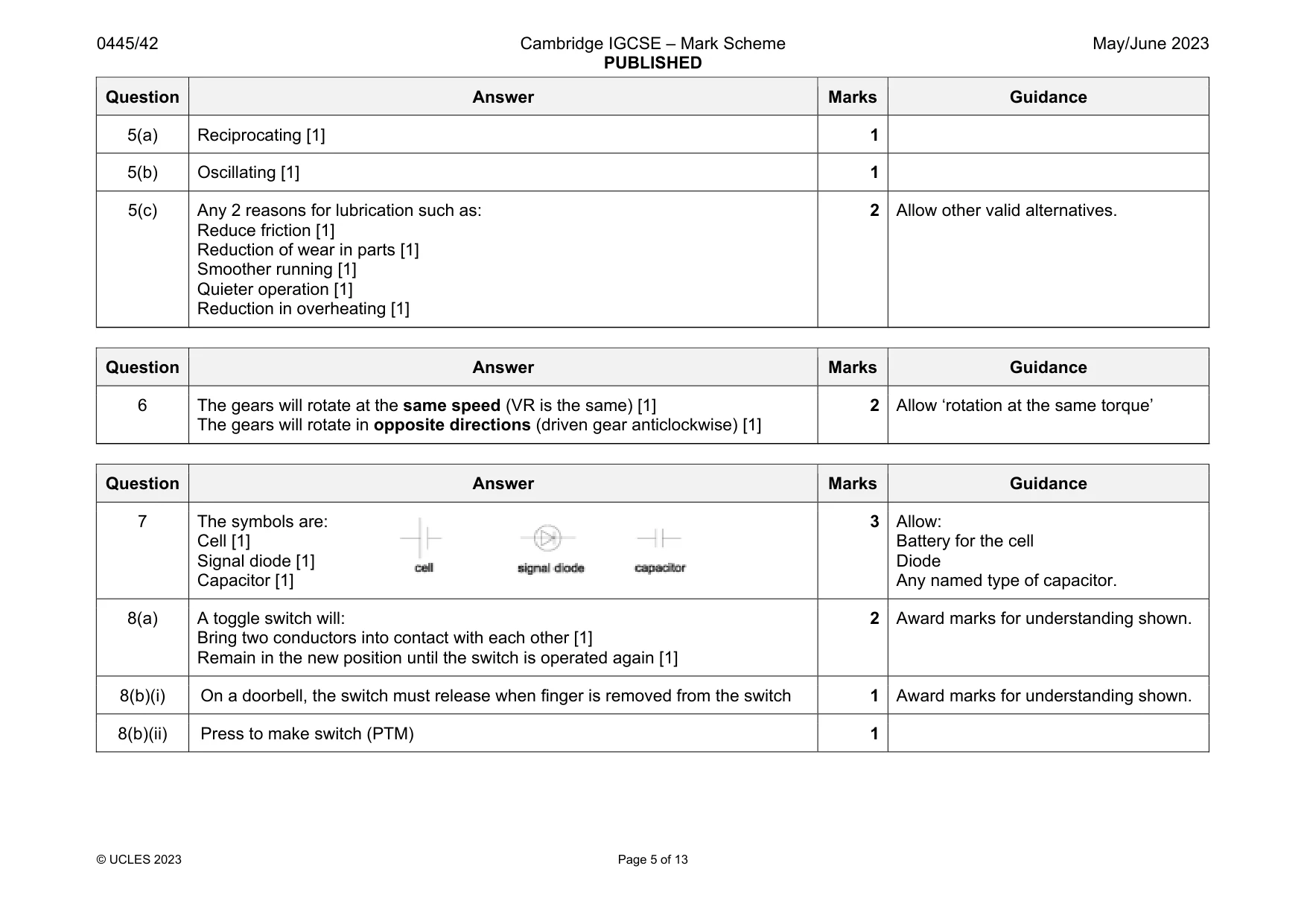
Mark scheme: 1 Coal [1] Natural gas [1] 2
Q2 · Give two reasons why many products are designed with a limited lifetime
2 Give two reasons why many products are designed with a limited lifetime. 1 ....................................................................................................................................................... .......................................................................................................................................................... 2 ....................................................................................................................................................... .......................................................................................................................................................... [2]
Mark scheme: 2 Any 2 reasons such as: To maintain an ongoing need for the product [1] To make use of new technology [1] To cut costs [1] Reduce ongoing need for spare parts [1]
Q3 · Name the types of structure shown in Fig
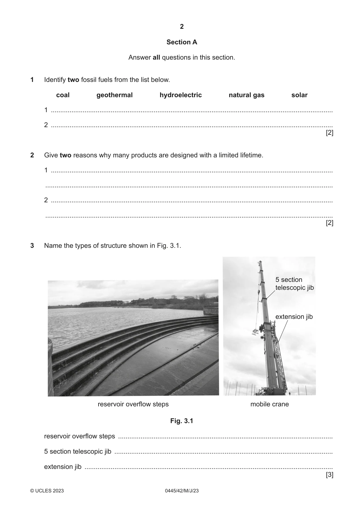
3 Name the types of structure shown in Fig. 3.1. 5 section telescopic jib extension jib reservoir overflow steps mobile crane Fig. 3.1 reservoir overflow steps ................................................................................................................... 5 section telescopic jib ..................................................................................................................... extension jib ..................................................................................................................................... [3]
Mark scheme: 3 Reservoir overflow steps – mass structure [1] 5 section telescopic jib – shell structure [1] Extension jib – frame structure [1] 3
Q4 · A beam that will be used in a structure
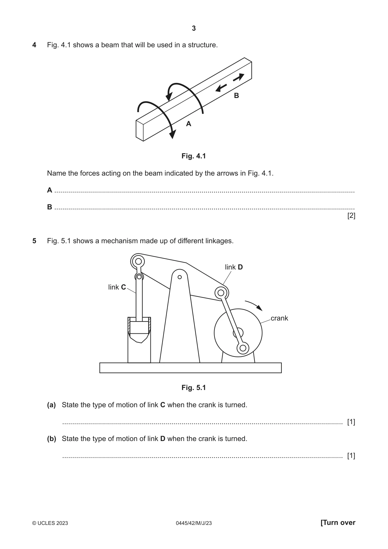
4 Fig. 4.1 shows a beam that will be used in a structure. B A Fig. 4.1 Name the forces acting on the beam indicated by the arrows in Fig. 4.1. A ....................................................................................................................................................... B ....................................................................................................................................................... [2]
Mark scheme: 4 Force A - torsion [1] Force B - tension [1] 2 Allow ‘torque’ for torsion
Q5 · A mechanism made up of different linkages
5 Fig. 5.1 shows a mechanism made up of different linkages. link D link C crank Fig. 5.1 (a) State the type of motion of link C when the crank is turned. ............................................................................................................................................. [1] (b) State the type of motion of link D when the crank is turned. ............................................................................................................................................. [1] (c) Give two reasons for providing lubrication to the linkages. 1 ................................................................................................................................................ ................................................................................................................................................... 2 ................................................................................................................................................ ................................................................................................................................................... [2]
Mark scheme: 5(a) Reciprocating [1] 1 5(b) Oscillating [1] 1 5(c) Any 2 reasons for lubrication such as: Reduce friction [1] Reduction of wear in parts [1] Smoother running [1] Quieter operation [1] Reduction in overheating [1] 2 Allow other valid alternatives.
Question 6
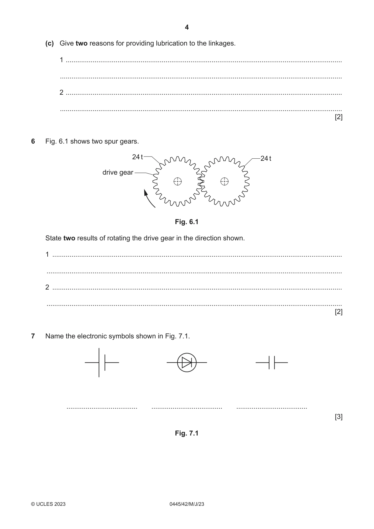
6 Fig. 6.1 shows two spur gears. 24 t 24 t drive gear Fig. 6.1 State two results of rotating the drive gear in the direction shown. 1 ....................................................................................................................................................... .......................................................................................................................................................... 2 ....................................................................................................................................................... .......................................................................................................................................................... [2]
Mark scheme: 6 The gears will rotate at the same speed (VR is the same) [1] The gears will rotate in opposite directions (driven gear anticlockwise) [1] 2 Allow ‘rotation at the same torque’
Q7 · Name the electronic symbols shown in Fig
7 Name the electronic symbols shown in Fig. 7.1. ..................................... ..................................... ..................................... [3] Fig. 7.1
Mark scheme: 7 The symbols are: Cell [1] Signal diode [1] Capacitor [1] Battery for the cell Diode Any named type of capacitor.
Question 8
8 Fig. 8.1 shows a toggle switch. Fig. 8.1 (a) Describe the function of a toggle switch used to control a light. ................................................................................................................................................... ................................................................................................................................................... ............................................................................................................................................. [2] (b) (i) Give one reason why a toggle switch would be unsuitable for use on a doorbell. ..................................................................................................................................... [1] (ii) Name a type of switch that would be suitable for use on a doorbell. ..................................................................................................................................... [1]
Mark scheme: 8(a) A toggle switch will: Bring two conductors into contact with each other [1] Remain in the new position until the switch is operated again [1] 2 Award marks for understanding shown. 8(b)(i) On a doorbell, the switch must release when finger is removed from the switch 1 Award marks for understanding shown. 8(b)(ii) Press to make switch (PTM) 1
Q9 · The list below shows abbreviations for multiple and sub-multiple units of capacitance
9 The list below shows abbreviations for multiple and sub-multiple units of capacitance. F pF µF nF Arrange the units in Table 9.1 in order of size. Table 9.1 smallest largest [3]
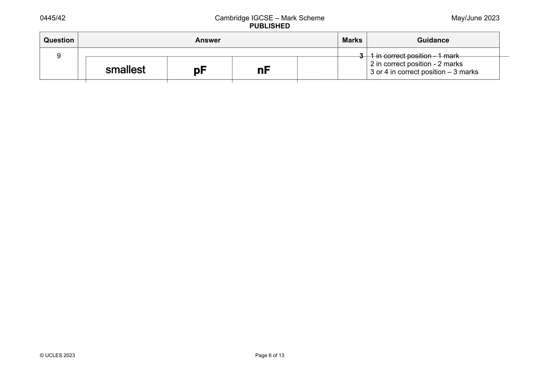
Mark scheme: 9 3 1 in correct position - 1 mark 2 in correct position - 2 marks 3 or 4 in correct position – 3 marks
Q10 · An adjustable steel trestle used by builders to reach heights safely
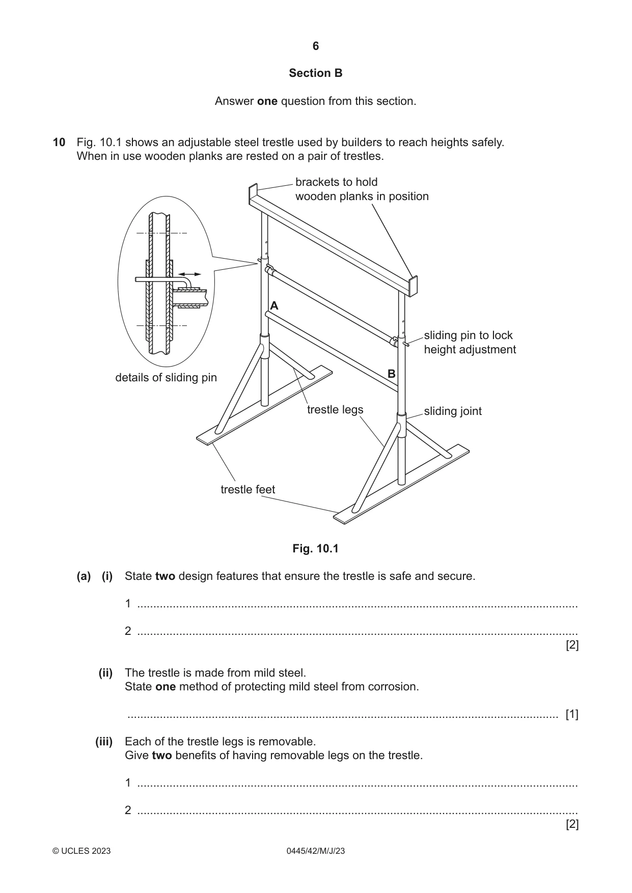
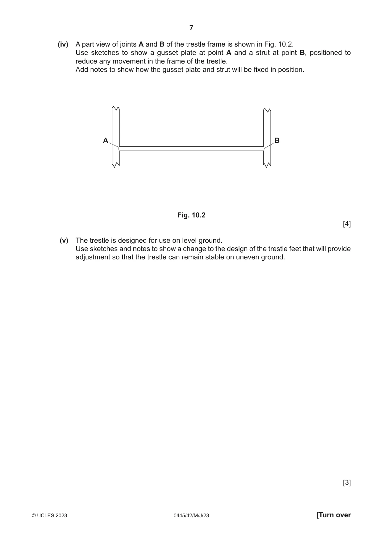
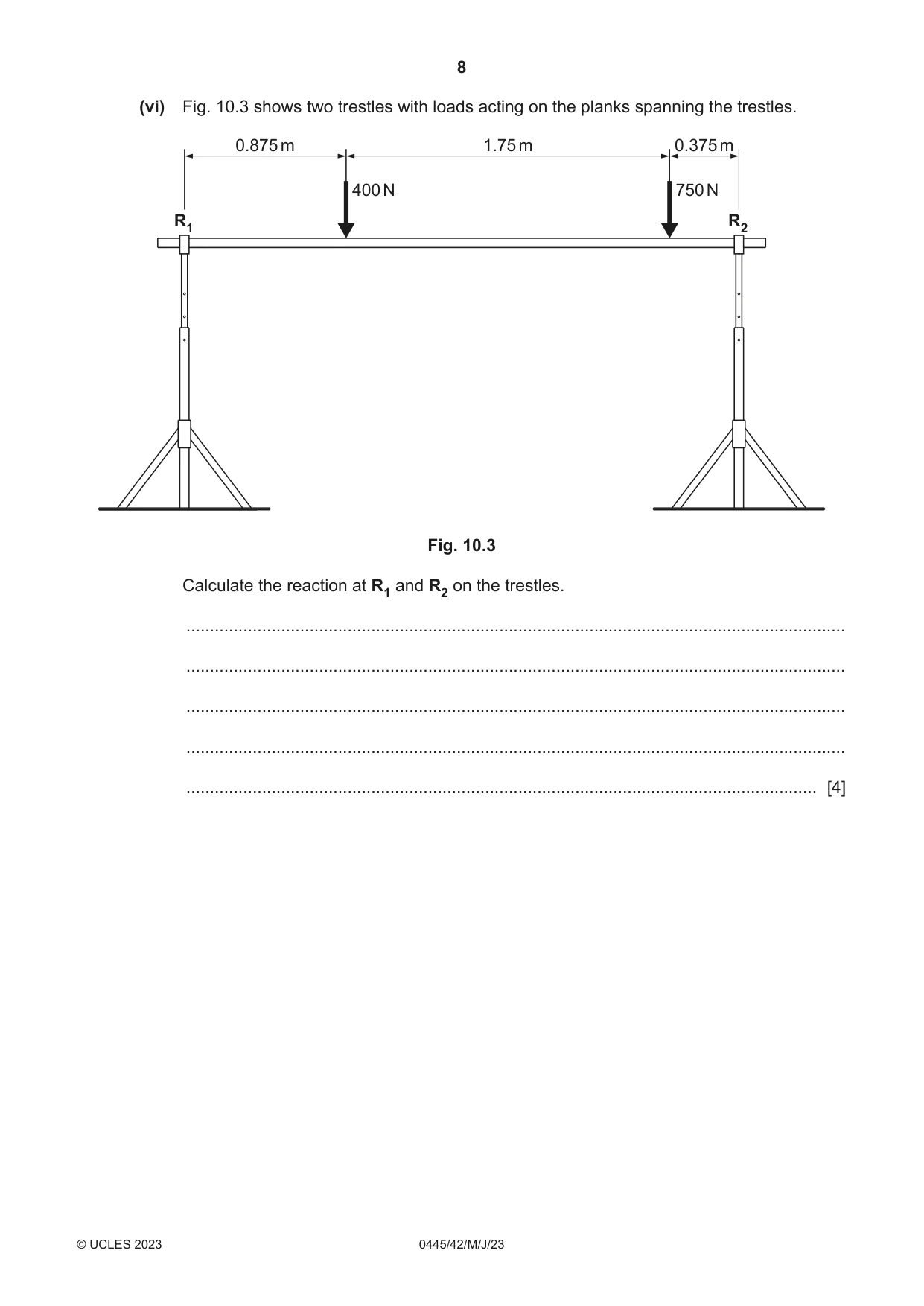
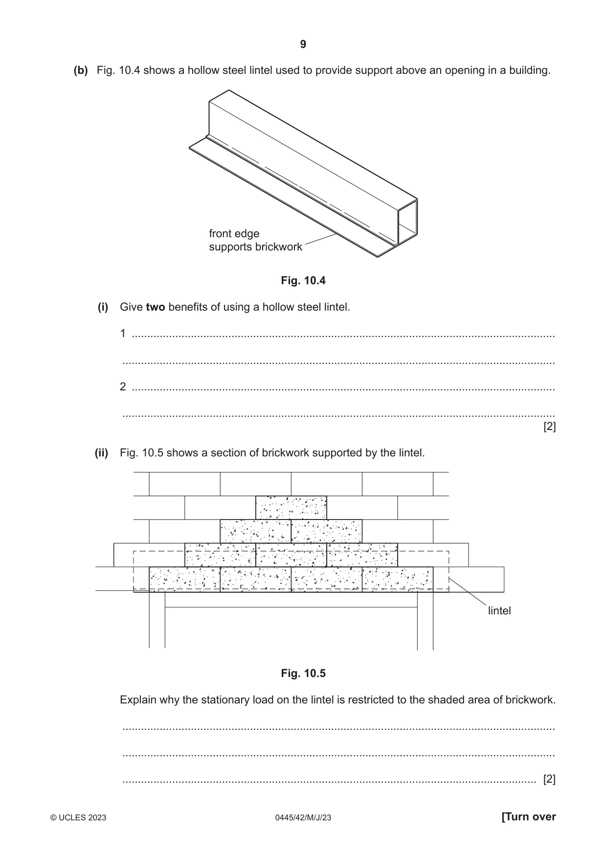
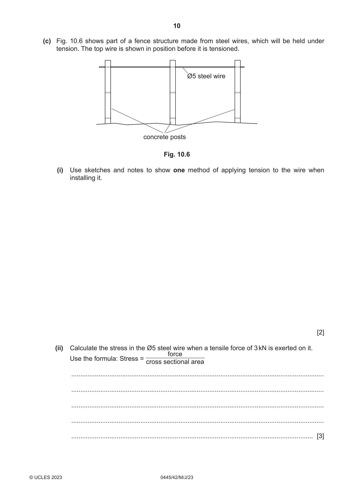
10 Fig. 10.1 shows an adjustable steel trestle used by builders to reach heights safely. When in use wooden planks are rested on a pair of trestles. brackets to hold wooden planks in position A sliding pin to lock height adjustment details of sliding pin B trestle legs sliding joint trestle feet Fig. 10.1 (a) (i) State two design features that ensure the trestle is safe and secure. 1 ........................................................................................................................................ 2 ........................................................................................................................................ [2] (ii) The trestle is made from mild steel. State one method of protecting mild steel from corrosion. ..................................................................................................................................... [1] (iii) Each of the trestle legs is removable. Give two benefits of having removable legs on the trestle. 1 ........................................................................................................................................ 2 ........................................................................................................................................ [2] (iv) A part view of joints A and B of the trestle frame is shown in Fig. 10.2. Use sketches to show a gusset plate at point A and a strut at point B, positioned to reduce any movement in the frame of the trestle. Add notes to show how the gusset plate and strut will be fixed in position. A B Fig. 10.2 [4] (v) The trestle is designed for use on level ground. Use sketches and notes to show a change to the design of the trestle feet that will provide adjustment so that the trestle can remain stable on uneven ground. [3] (vi) Fig. 10.3 shows two trestles with loads acting on the planks spanning the trestles. 0.875 m 1.75 m 0.375 m 400 N 750 N R1 R2 Fig. 10.3 Calculate the reaction at R1 and R2 on the trestles. ........................................................................................................................................... ........................................................................................................................................... ........................................................................................................................................... ........................................................................................................................................... ..................................................................................................................................... [4] (b) Fig. 10.4 shows a hollow steel lintel used to provide support above an opening in a building. front edge supports brickwork Fig. 10.4 (i) Give two benefits of using a hollow steel lintel. 1 ........................................................................................................................................ ........................................................................................................................................... 2 ........................................................................................................................................ ........................................................................................................................................... [2] (ii) Fig. 10.5 shows a section of brickwork supported by the lintel. lintel Fig. 10.5 Explain why the stationary load on the lintel is restricted to the shaded area of brickwork. ........................................................................................................................................... ........................................................................................................................................... ..................................................................................................................................... [2] (c) Fig. 10.6 shows part of a fence structure made from steel wires, which will be held under tension. The top wire is shown in position before it is tensioned. Ø5 steel wire concrete posts Fig. 10.6 (i) Use sketches and notes to show one method of applying tension to the wire when installing it. [2] (ii) Calculate the stress in the Ø5 steel wire when a tensile force of 3 kN is exerted on it. force Use the formula: Stress = cross sectional area ........................................................................................................................................... ........................................................................................................................................... ........................................................................................................................................... ........................................................................................................................................... ..................................................................................................................................... [3]
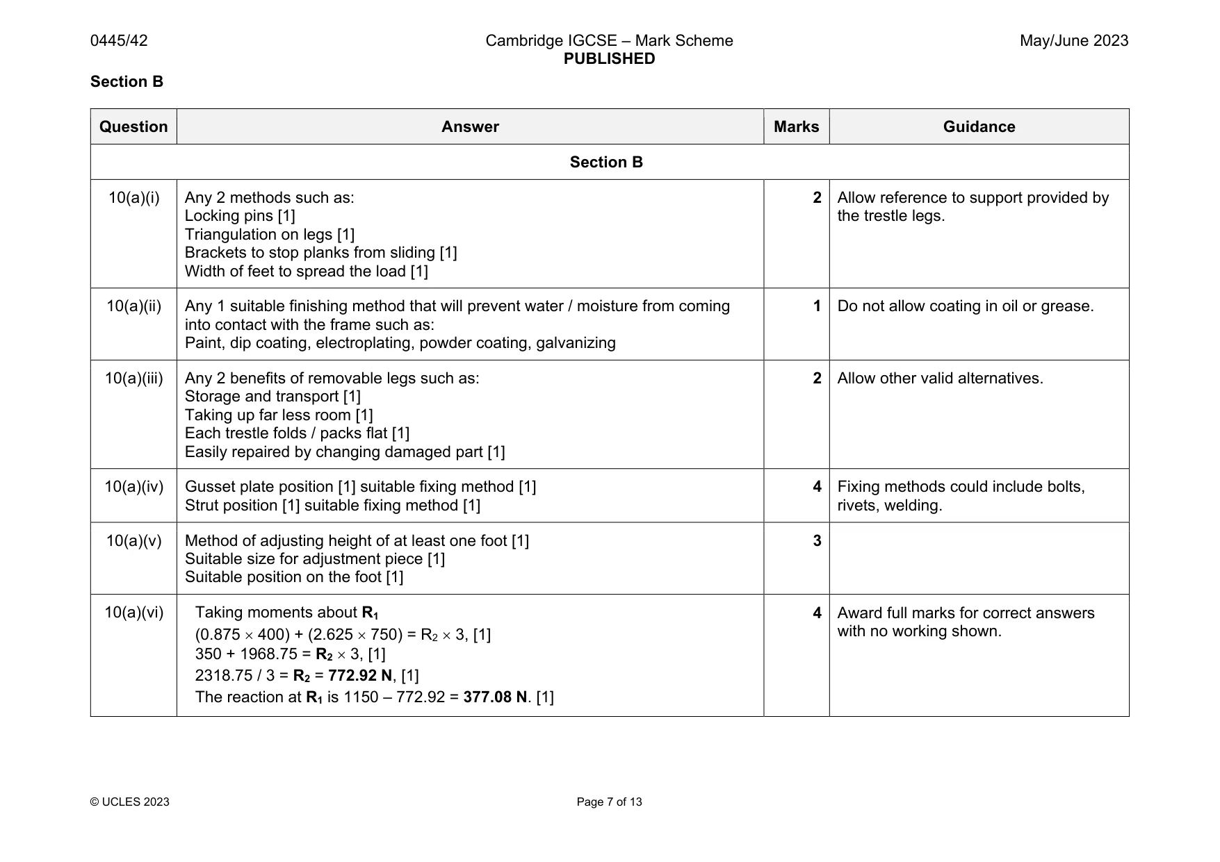
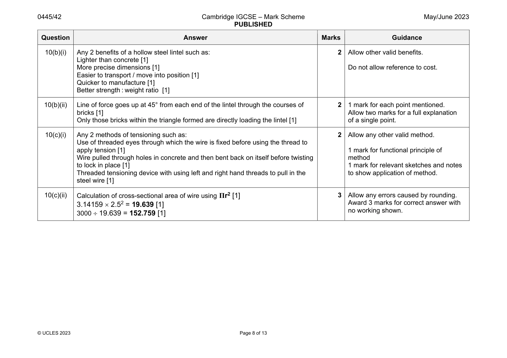
Mark scheme: 10(a)(i) Any 2 methods such as: Locking pins [1] Triangulation on legs [1] Brackets to stop planks from sliding [1] Width of feet to spread the load [1] the trestle legs. 10(a)(ii) Any 1 suitable finishing method that will prevent water / moisture from coming into contact with the frame such as: Paint, dip coating, electroplating, powder coating, galvanizing 1 Do not allow coating in oil or grease. 10(a)(iii) Any 2 benefits of removable legs such as: Storage and transport [1] Taking up far less room [1] Each trestle folds / packs flat [1] Easily repaired by changing damaged part [1] 2 Allow other valid alternatives. 10(a)(iv) Gusset plate position [1] suitable fixing method [1] Strut position [1] suitable fixing method [1] 4 Fixing methods could include bolts, rivets, welding. 10(a)(v) Method of adjusting height of at least one foot [1] Suitable size for adjustment piece [1] Suitable position on the foot [1] 3 10(a)(vi) Taking moments about R1 (0.875 400) + (2.625 750) = R2 3, [1] 350 + 1968.75 = R2 3, [1] 2318.75 / 3 = R2 = 772.92 N, [1] The reaction at R1 is 1150 – 772.92 = 377.08 N. [1] 4 Award full marks for correct answers with no working shown. Question Answer Marks Guidance 10(b)(i) Any 2 benefits of a hollow steel lintel such as: Lighter than concrete [1] More precise dimensions [1] Easier to transport / move into position [1] Quicker to manufacture [1] Better strength : weight ratio [1] 2 Allow other valid benefits. Do not allow reference to cost. 10(b)(ii) Line of force goes up at 45° from each end of the lintel through the courses of bricks [1] Only those bricks within the triangle formed are directly loading the lintel [1] 2 1 mark for each point mentioned. Allow two marks for a full explanation of a single point. 10(c)(i) Any 2 methods of tensioning such as: Use of threaded eyes through which the wire is fixed before using the thread to apply tension [1] Wire pulled through holes in concrete and then bent back on itself before twisting to lock in place [1] Threaded tensioning device with using left and right hand threads to pull in the steel wire [1] 2 Allow any other valid method. 1 mark for functional principle of method 1 mark for relevant sketches and notes to show application of method. 10(c)(ii) Calculation of cross-sectional area of wire using Πr2 [1] 3.14159 2.52 = 19.639 [1] 3000 19.639 = 152.759 [1] 3 Allow any errors caused by rounding. Award 3 marks for correct answer with no working shown.
Q11 · A part of a bicycle chain with four positions identified
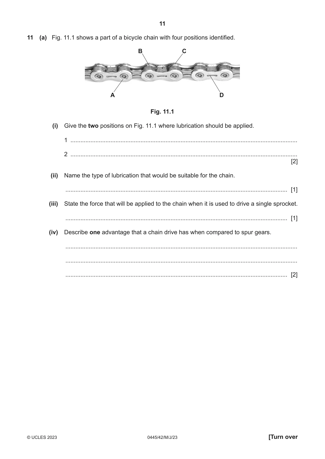
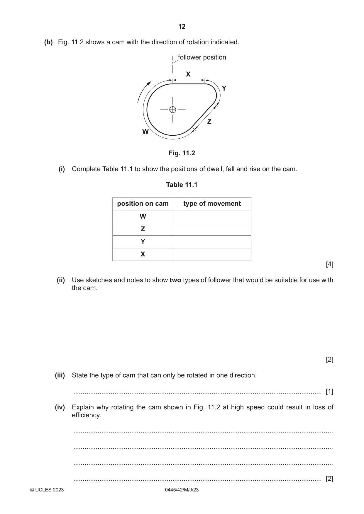
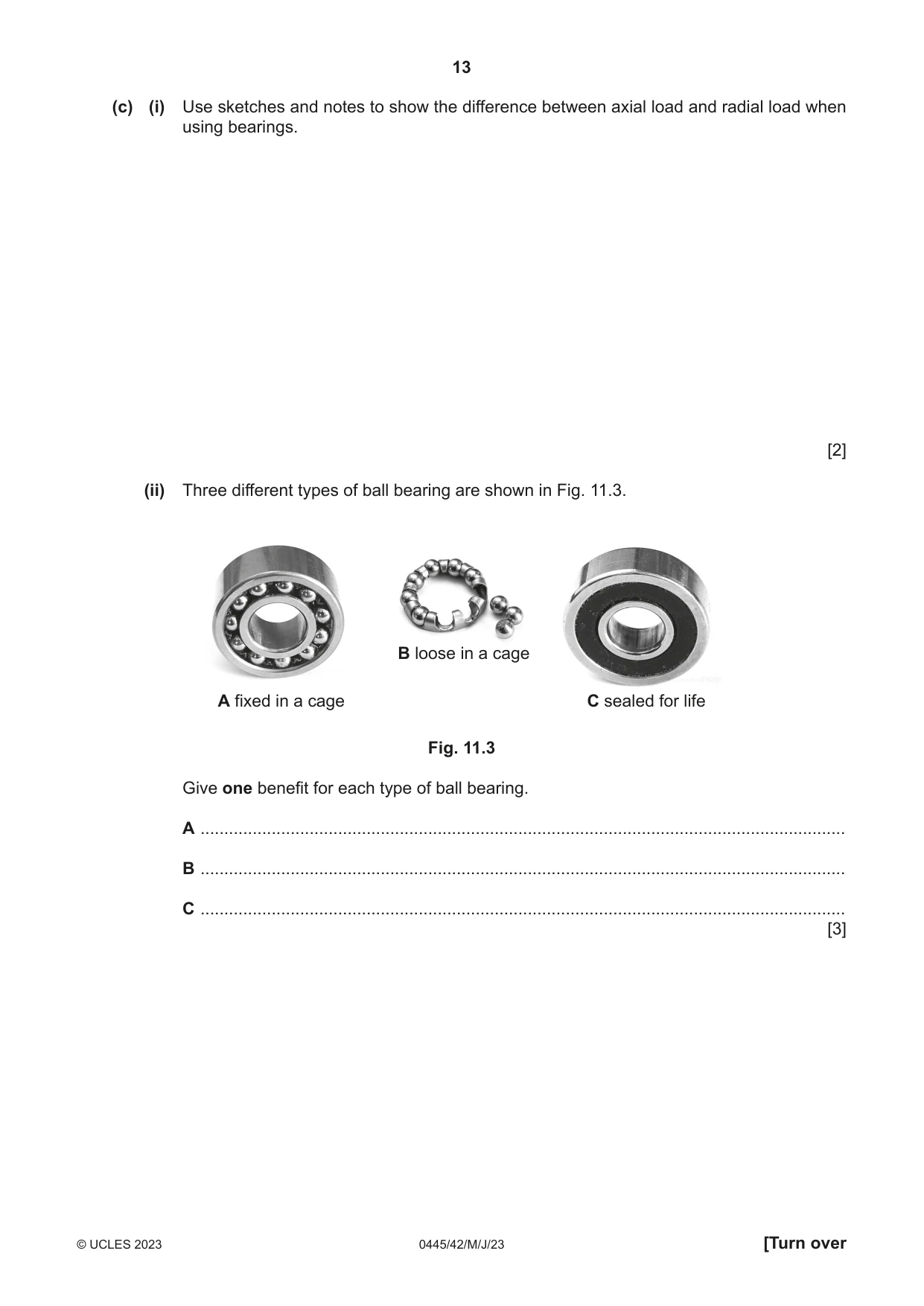
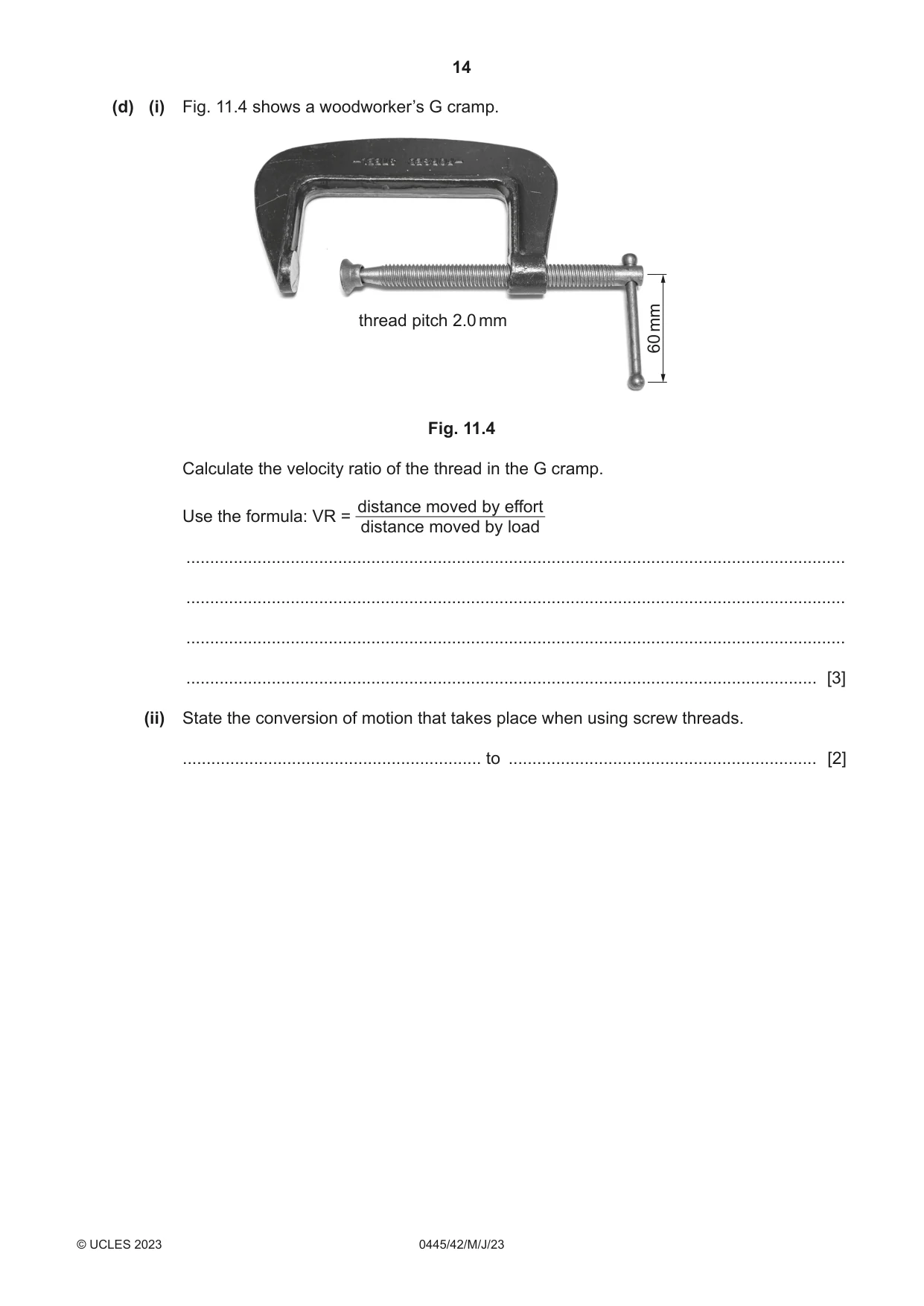
11 (a) Fig. 11.1 shows a part of a bicycle chain with four positions identified. B C A D Fig. 11.1 (i) Give the two positions on Fig. 11.1 where lubrication should be applied. 1 ........................................................................................................................................ 2 ........................................................................................................................................ [2] (ii) Name the type of lubrication that would be suitable for the chain. ..................................................................................................................................... [1] (iii) State the force that will be applied to the chain when it is used to drive a single sprocket. ..................................................................................................................................... [1] (iv) Describe one advantage that a chain drive has when compared to spur gears. ........................................................................................................................................... ........................................................................................................................................... ..................................................................................................................................... [2] (b) Fig. 11.2 shows a cam with the direction of rotation indicated. follower position X Y Z W Fig. 11.2 (i) Complete Table 11.1 to show the positions of dwell, fall and rise on the cam. Table 11.1 position on cam type of movement W Z Y X [4] (ii) Use sketches and notes to show two types of follower that would be suitable for use with the cam. [2] (iii) State the type of cam that can only be rotated in one direction. ..................................................................................................................................... [1] (iv) Explain why rotating the cam shown in Fig. 11.2 at high speed could result in loss of efficiency. ........................................................................................................................................... ........................................................................................................................................... ........................................................................................................................................... ..................................................................................................................................... [2] (c) (i) Use sketches and notes to show the difference between axial load and radial load when using bearings. [2] (ii) Three different types of ball bearing are shown in Fig. 11.3. B loose in a cage A fixed in a cage C sealed for life Fig. 11.3 Give one benefit for each type of ball bearing. A ........................................................................................................................................ B ........................................................................................................................................ C ........................................................................................................................................ [3] (d) (i) Fig. 11.4 shows a woodworker’s G cramp. thread pitch 2.0 mm mm 60 Fig. 11.4 Calculate the velocity ratio of the thread in the G cramp. distance moved by effort Use the formula: VR = distance moved by load ........................................................................................................................................... ........................................................................................................................................... ........................................................................................................................................... ..................................................................................................................................... [3] (ii) State the conversion of motion that takes place when using screw threads. ............................................................... to ................................................................. [2]
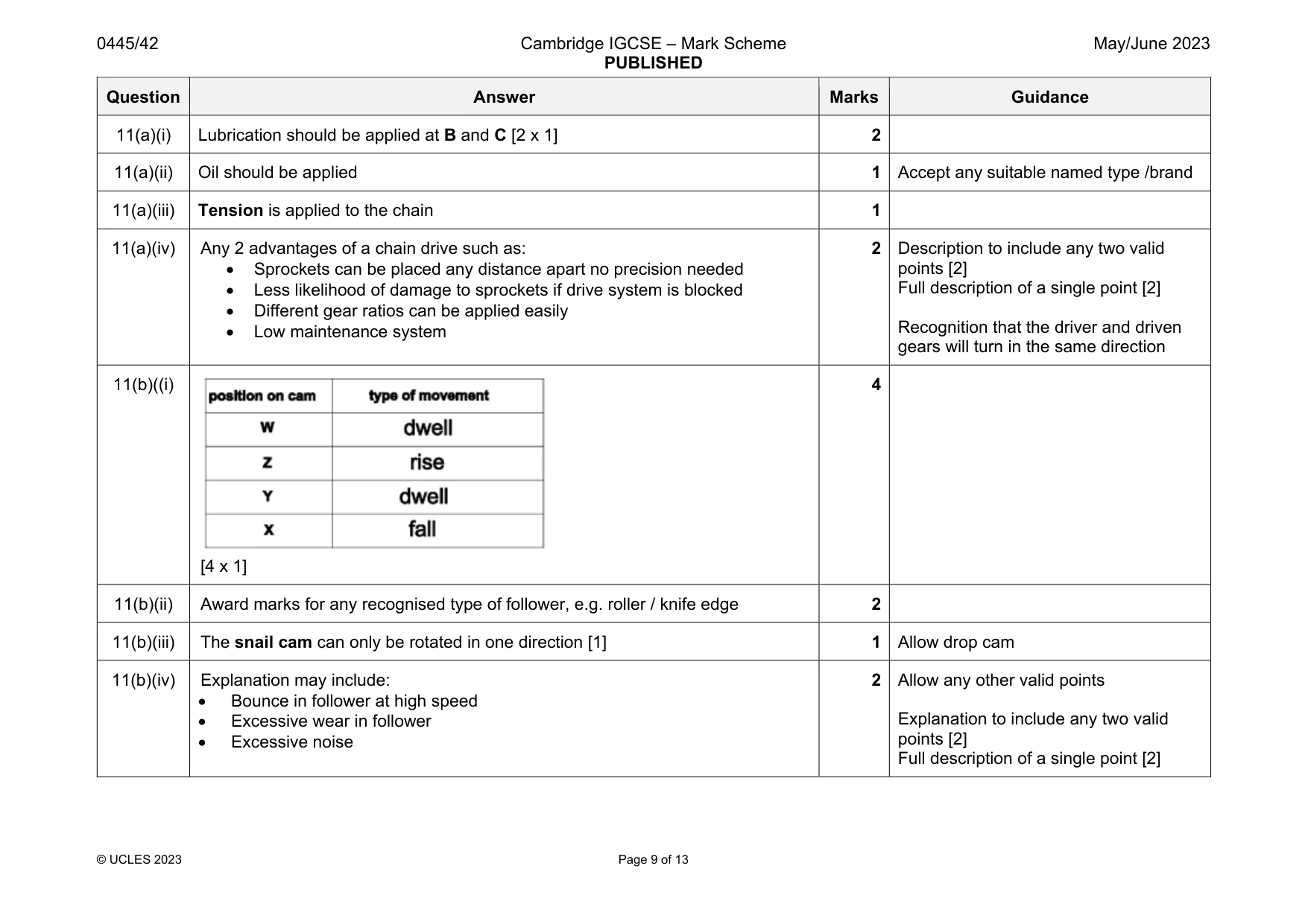
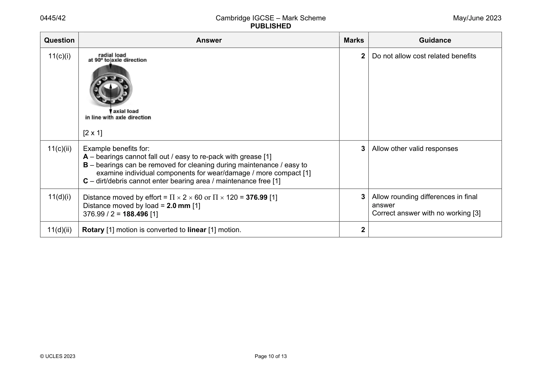
Mark scheme: 11(a)(i) Lubrication should be applied at B and C [2 x 1] 2 11(a)(ii) Oil should be applied 1 Accept any suitable named type /brand 11(a)(iii) Tension is applied to the chain 1 11(a)(iv) Any 2 advantages of a chain drive such as: Sprockets can be placed any distance apart no precision needed Less likelihood of damage to sprockets if drive system is blocked Different gear ratios can be applied easily Low maintenance system 2 Description to include any two valid points [2] Full description of a single point [2] Recognition that the driver and driven gears will turn in the same direction 11(b)((i) [4 x 1] 4 11(b)(ii) Award marks for any recognised type of follower, e.g. roller / knife edge 2 11(b)(iii) The snail cam can only be rotated in one direction [1] 1 Allow drop cam 11(b)(iv) Explanation may include: Bounce in follower at high speed Excessive wear in follower Excessive noise 2 Allow any other valid points Explanation to include any two valid points [2] Full description of a single point [2] Question Answer Marks Guidance 11(c)(i) [2 x 1] 2 Do not allow cost related benefits 11(c)(ii) Example benefits for: A – bearings cannot fall out / easy to re-pack with grease [1] B – bearings can be removed for cleaning during maintenance / easy to examine individual components for wear/damage / more compact [1] C – dirt/debris cannot enter bearing area / maintenance free [1] 3 Allow other valid responses 11(d)(i) Distance moved by effort = Π 2 60 or Π 120 = 376.99 [1] Distance moved by load = 2.0 mm [1] 376.99 / 2 = 188.496 [1] 3 Allow rounding differences in final answer Correct answer with no working [3] 11(d)(ii) Rotary [1] motion is converted to linear [1] motion. 2
Q12 · A rechargeable cycle light which uses high intensity LEDs
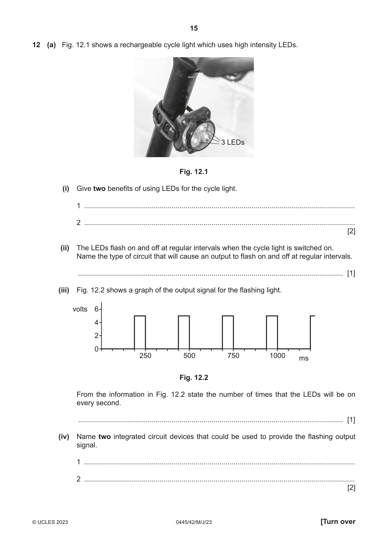
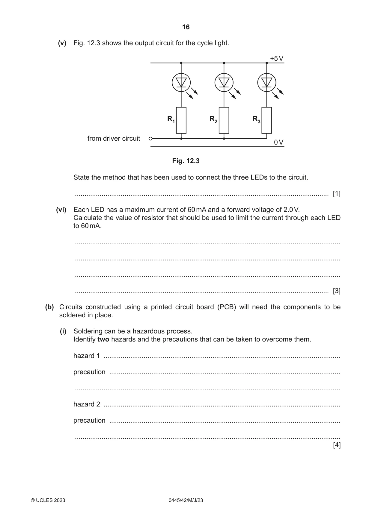
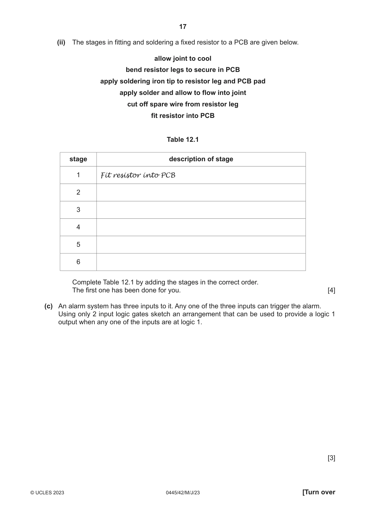
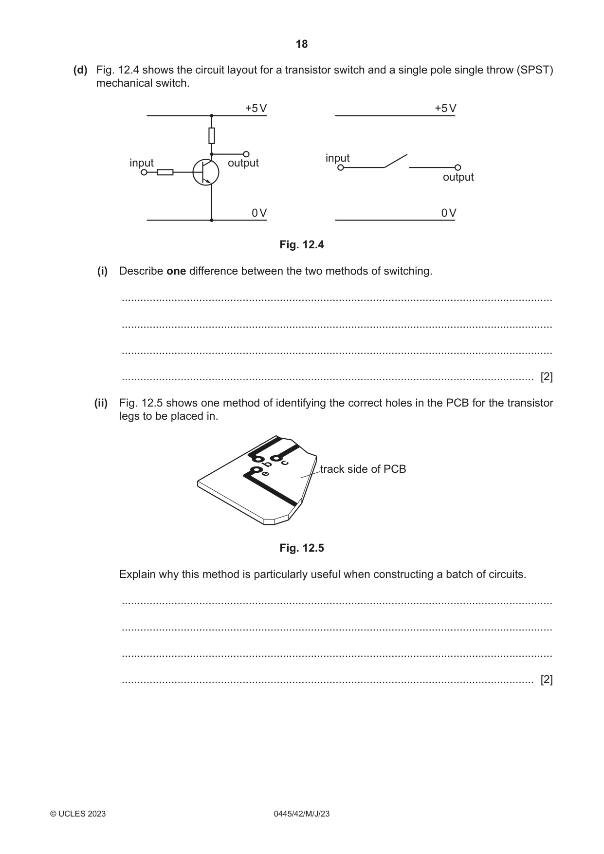
12 (a) Fig. 12.1 shows a rechargeable cycle light which uses high intensity LEDs. 3 LEDs Fig. 12.1 (i) Give two benefits of using LEDs for the cycle light. 1 ........................................................................................................................................ 2 ........................................................................................................................................ [2] (ii) The LEDs flash on and off at regular intervals when the cycle light is switched on. Name the type of circuit that will cause an output to flash on and off at regular intervals. ..................................................................................................................................... [1] (iii) Fig. 12.2 shows a graph of the output signal for the flashing light. volts 6 4 2 0 250 500 750 1000 ms Fig. 12.2 From the information in Fig. 12.2 state the number of times that the LEDs will be on every second. ..................................................................................................................................... [1] (iv) Name two integrated circuit devices that could be used to provide the flashing output signal. 1 ........................................................................................................................................ 2 ........................................................................................................................................ [2] (v) Fig. 12.3 shows the output circuit for the cycle light. +5 V R1 R2 R3 from driver circuit 0 V Fig. 12.3 State the method that has been used to connect the three LEDs to the circuit. ..................................................................................................................................... [1] (vi) Each LED has a maximum current of 60 mA and a forward voltage of 2.0 V. Calculate the value of resistor that should be used to limit the current through each LED to 60 mA. ........................................................................................................................................... ........................................................................................................................................... ........................................................................................................................................... ..................................................................................................................................... [3] (b) Circuits constructed using a printed circuit board (PCB) will need the components to be soldered in place. (i) Soldering can be a hazardous process. Identify two hazards and the precautions that can be taken to overcome them. hazard 1 ............................................................................................................................ precaution ......................................................................................................................... ........................................................................................................................................... hazard 2 ............................................................................................................................ precaution ......................................................................................................................... ........................................................................................................................................... [4] (ii) The stages in fitting and soldering a fixed resistor to a PCB are given below. allow joint to cool bend resistor legs to secure in PCB apply soldering iron tip to resistor leg and PCB pad apply solder and allow to flow into joint cut off spare wire from resistor leg fit resistor into PCB Table 12.1 stage description of stage 1 Fit resistor into PCB 2 3 4 5 6 Complete Table 12.1 by adding the stages in the correct order. The first one has been done for you. [4] (c) An alarm system has three inputs to it. Any one of the three inputs can trigger the alarm. Using only 2 input logic gates sketch an arrangement that can be used to provide a logic 1 output when any one of the inputs are at logic 1. [3]
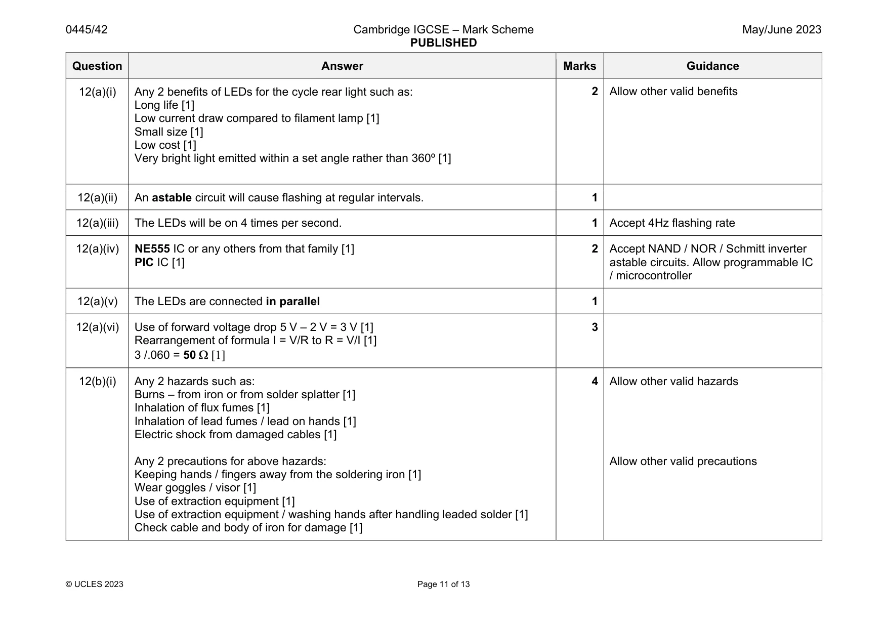
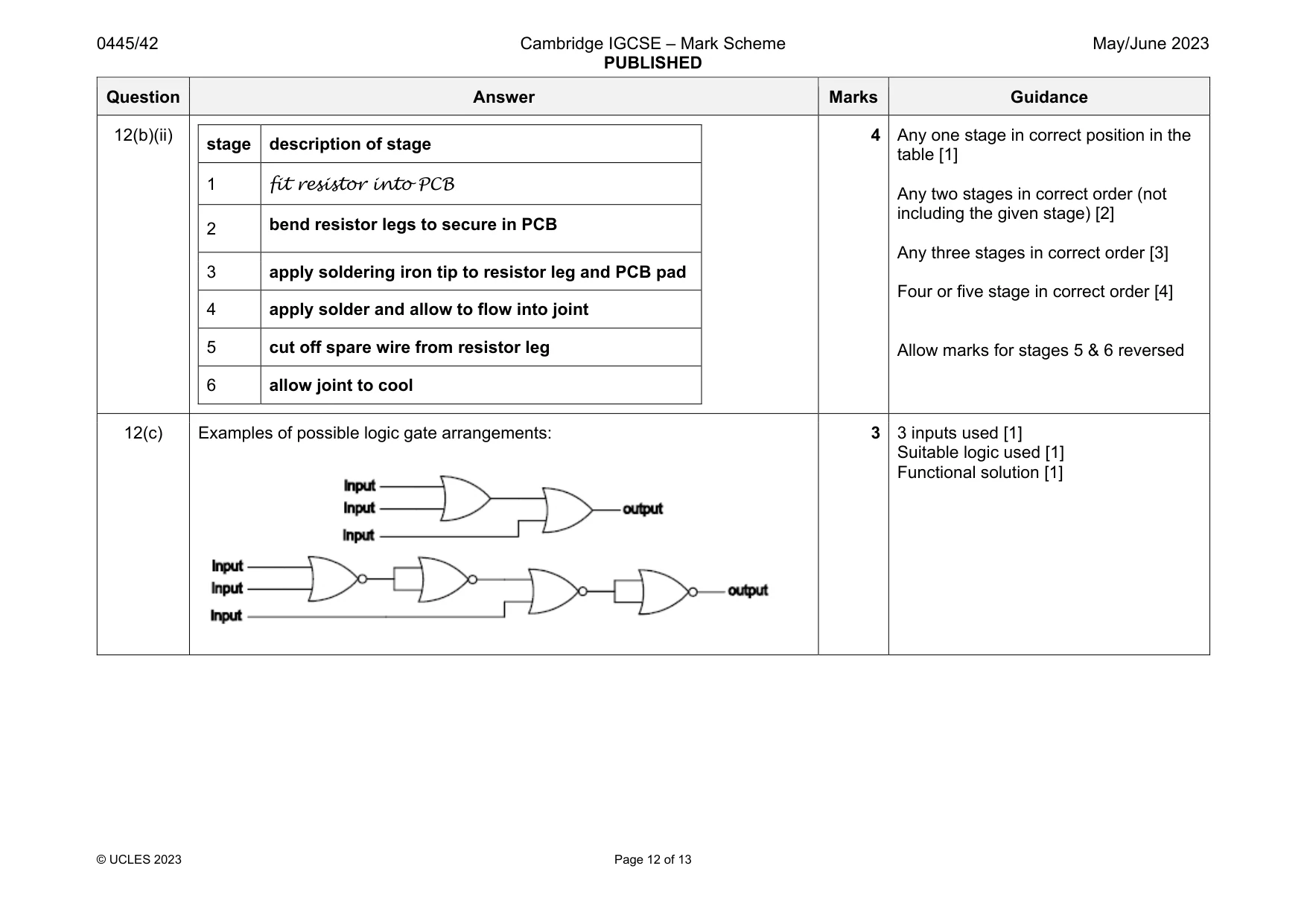
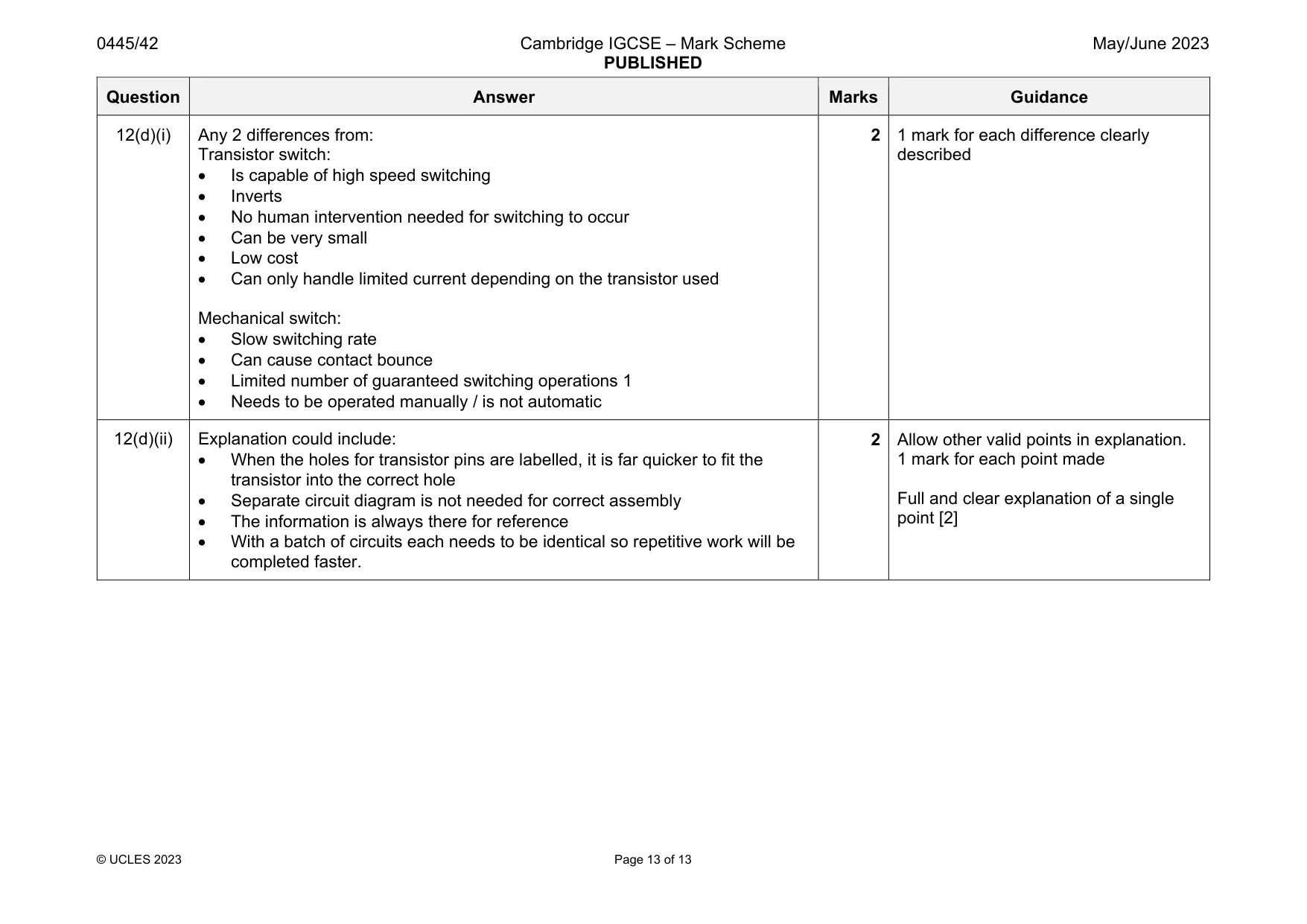
Mark scheme: 12(a)(i) Any 2 benefits of LEDs for the cycle rear light such as: Long life [1] Low current draw compared to filament lamp [1] Small size [1] Low cost [1] Very bright light emitted within a set angle rather than 360º [1] 12(a)(ii) An astable circuit will cause flashing at regular intervals. 1 12(a)(iii) The LEDs will be on 4 times per second. 1 Accept 4Hz flashing rate 12(a)(iv) NE555 IC or any others from that family [1] PIC IC [1] 2 Accept NAND / NOR / Schmitt inverter astable circuits. Allow programmable IC / microcontroller 12(a)(v) The LEDs are connected in parallel 1 12(a)(vi) Use of forward voltage drop 5 V – 2 V = 3 V [1] Rearrangement of formula I = V/R to R = V/I [1] 3 /.060 = 50 3 12(b)(i) Any 2 hazards such as: Burns – from iron or from solder splatter [1] Inhalation of flux fumes [1] Inhalation of lead fumes / lead on hands [1] Electric shock from damaged cables [1] Any 2 precautions for above hazards: Keeping hands / fingers away from the soldering iron [1] Wear goggles / visor [1] Use of extraction equipment [1] Use of extraction equipment / washing hands after handling leaded solder [1] Check cable and body of iron for damage [1] 4 Allow other valid hazards Allow other valid precautions Question Answer Marks Guidance 12(b)(ii) stage description of stage 1 fit resistor into PCB 2 bend resistor legs to secure in PCB 3 apply soldering iron tip to resistor leg and PCB pad 4 apply solder and allow to flow into joint 5 cut off spare wire from resistor leg 6 allow joint to cool 4 Any one stage in correct position in the table [1] Any two stages in correct order (not including the given stage) [2] Any three stages in correct order [3] Four or five stage in correct order [4] Allow marks for stages 5 & 6 reversed 12(c) Examples of possible logic gate arrangements: 3 3 inputs used [1] Suitable logic used [1] Functional solution [1] Question Answer Marks Guidance 12(d)(i) Any 2 differences from: Transistor switch: Is capable of high speed switching Inverts No human intervention needed for switching to occur Can be very small Low cost Can only handle limited current depending on the transistor used Mechanical switch: Slow switching rate Can cause contact bounce Limited number of guaranteed switching operations 1 Needs to be operated manually / is not automatic 2 1 mark for each difference clearly described 12(d)(ii) Explanation could include: When the holes for transistor pins are labelled, it is far quicker to fit the transistor into the correct hole Separate circuit diagram is not needed for correct assembly The information is always there for reference With a batch of circuits each needs to be identical so repetitive work will be completed faster. 2 Allow other valid points in explanation. 1 mark for each point made Full and clear explanation of a single point [2]
What was in this paper
The subtopics covered by these 12 questions, and how many questions each got. Open one in a new tab to see every Cambridge question on it.
What you needed in this session
Cambridge’s own grade thresholds for 2023 May/June, Paper 4 · Variant 2. A higher threshold means an easier paper — the bar moves with how the cohort did.