Cambridge IGCSE Design and Technology 0445 — 2022 May/June Paper 4 · Variant 2
0445/42/M/J/22 · 11 questions · 50 marks · ≈56 min
The question paper and its mark scheme, free to read here and free to download. This is Cambridge’s own paper, exactly as it was sat.
Question paper20 pages

Mark scheme14 pages
Answers below. Sit the paper first if you are practising.
Questions as text
Q1 · An adjustable height axle stand used to support the weight of a vehicle
1 Fig. 1.1 shows an adjustable height axle stand used to support the weight of a vehicle. central pin column base Fig. 1.1 (a) State three properties of mild steel that make it suitable for use in the base of the axle stand. 1 ................................................................................................................................................ 2 ................................................................................................................................................ 3 ................................................................................................................................................ [3] (b) Describe the type of structure used in the base of the axle stand. ................................................................................................................................................... ................................................................................................................................................... ............................................................................................................................................. [2] (c) The pin used to support the central column must resist shear force. Use sketches and notes to describe what is meant by ‘shear force’. [2]
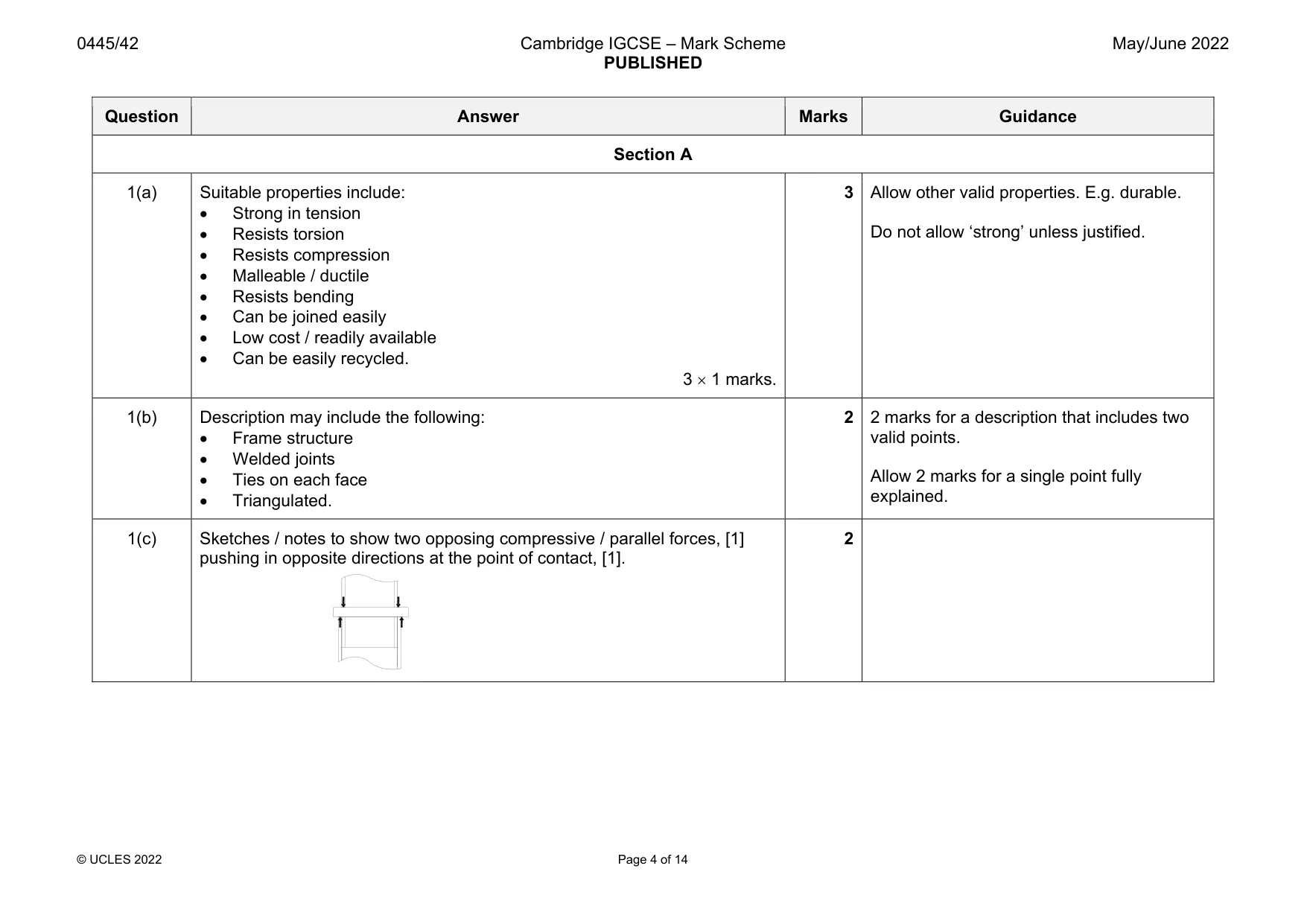
Mark scheme: 1(a) Suitable properties include: Strong in tension Resists torsion Resists compression Malleable / ductile Resists bending Can be joined easily Low cost / readily available Can be easily recycled. 3 1 marks. 3 Allow other valid properties. E.g. durable. Do not allow ‘strong’ unless justified. 1(b) Description may include the following: Frame structure Welded joints Ties on each face Triangulated. 2 2 marks for a description that includes two valid points. Allow 2 marks for a single point fully explained. 1(c) Sketches / notes to show two opposing compressive / parallel forces, [1] pushing in opposite directions at the point of contact, [1]. 2
Q2 · Give two reasons why a designer would need to reduce friction in a mechanism
2 (a) Give two reasons why a designer would need to reduce friction in a mechanism. 1 ................................................................................................................................................ ................................................................................................................................................... 2 ................................................................................................................................................ ................................................................................................................................................... [2] (b) State two methods that can be used to reduce friction in a mechanism. 1 ................................................................................................................................................ 2 ................................................................................................................................................ [2]
Mark scheme: 2(a) Reasons for reducing friction will include: Reducing wear on parts Lower running costs Reduce noise Improve efficiency in the mechanism Reduce heat 2 1 marks. 2 Allow other valid reasons 2(b) Methods will include: Use of lubrication Use of bearings/bearing material Reduction of area of mating parts Use of materials with low coefficient of friction e.g. nylon 2 1 marks for valid methods. 2
Q3 · Products can be designed and manufactured so that they can be disassembled
3 Products can be designed and manufactured so that they can be disassembled. Describe two benefits of being able to disassemble a product after manufacture. 1 ....................................................................................................................................................... .......................................................................................................................................................... 2 ....................................................................................................................................................... .......................................................................................................................................................... [2]
Mark scheme: 3 Benefits of ability to disassemble products will include: Ability to repair and replace parts Ease of transport Ease of storage Ease of packaging Product can be modified Different materials / parts can be separated for recycling and reuse. 2 1 marks.
Q4 · A clock that uses a mechanism to convert motion
4 Fig. 4.1 shows a clock that uses a mechanism to convert motion. pendulum Fig. 4.1 (a) State the type of motion produced by the pendulum. ............................................................................................................................................. [1] (b) State the type of motion produced by the clock hands. ............................................................................................................................................. [1]
Mark scheme: 4(a) Oscillating motion is produced by the pendulum. 1 4(b) Rotary motion is produced by the clock hands. 1
Q5 · Describe, using one example, how computers can be used by a manufacturer to increase…
5 Describe, using one example, how computers can be used by a manufacturer to increase efficiency in stock control. .......................................................................................................................................................... .......................................................................................................................................................... .......................................................................................................................................................... .................................................................................................................................................... [3]
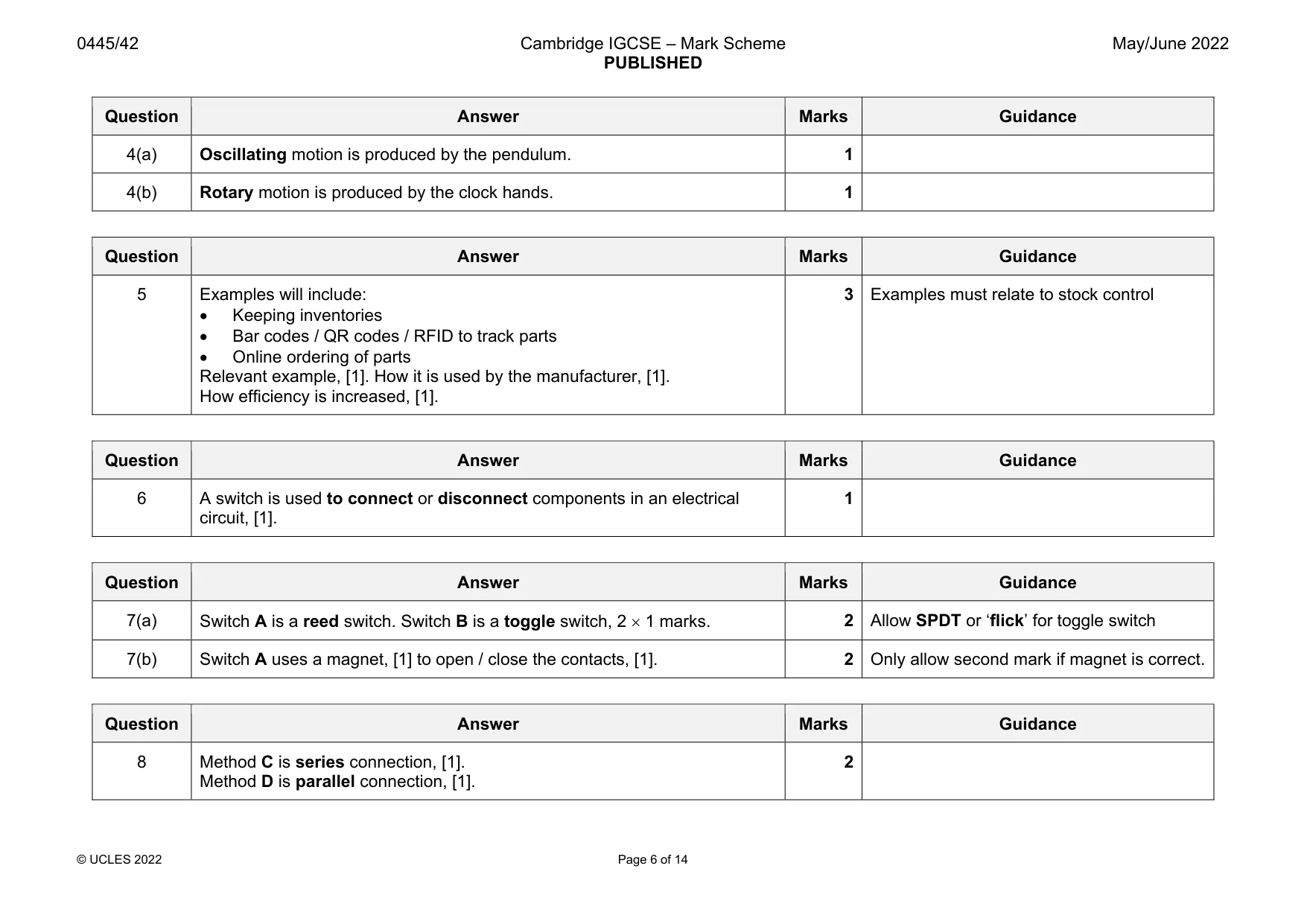
Mark scheme: 5 Examples will include: Keeping inventories Bar codes / QR codes / RFID to track parts Online ordering of parts Relevant example, [1]. How it is used by the manufacturer, [1]. How efficiency is increased, [1]. 3 Examples must relate to stock control
Q6 · State the function of an electrical switch
6 State the function of an electrical switch. .......................................................................................................................................................... .................................................................................................................................................... [1]
Mark scheme: 6 A switch is used to connect or disconnect components in an electrical circuit, [1]. 1
Q7 · Name the two types of switch shown in Fig
7 (a) Name the two types of switch shown in Fig. 7.1. A B Fig. 7.1 Switch A .................................................................................................................................... Switch B ................................................................................................................................... [2] (b) Describe how switch A is operated. ................................................................................................................................................... ................................................................................................................................................... ............................................................................................................................................. [2]
Mark scheme: 7(a) 2 Allow SPDT or ‘flick’ for toggle switch 7(b) Switch A uses a magnet, [1] to open / close the contacts, [1]. 2 Only allow second mark if magnet is correct.
Q8 · Two methods of connecting switches in a circuit
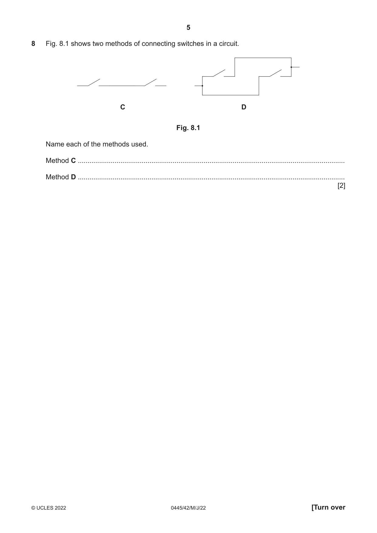
8 Fig. 8.1 shows two methods of connecting switches in a circuit. C D Fig. 8.1 Name each of the methods used. Method C .......................................................................................................................................... Method D .......................................................................................................................................... [2]
Mark scheme: 8 Method C is series connection, [1]. Method D is parallel connection, [1]. 2
Question 9
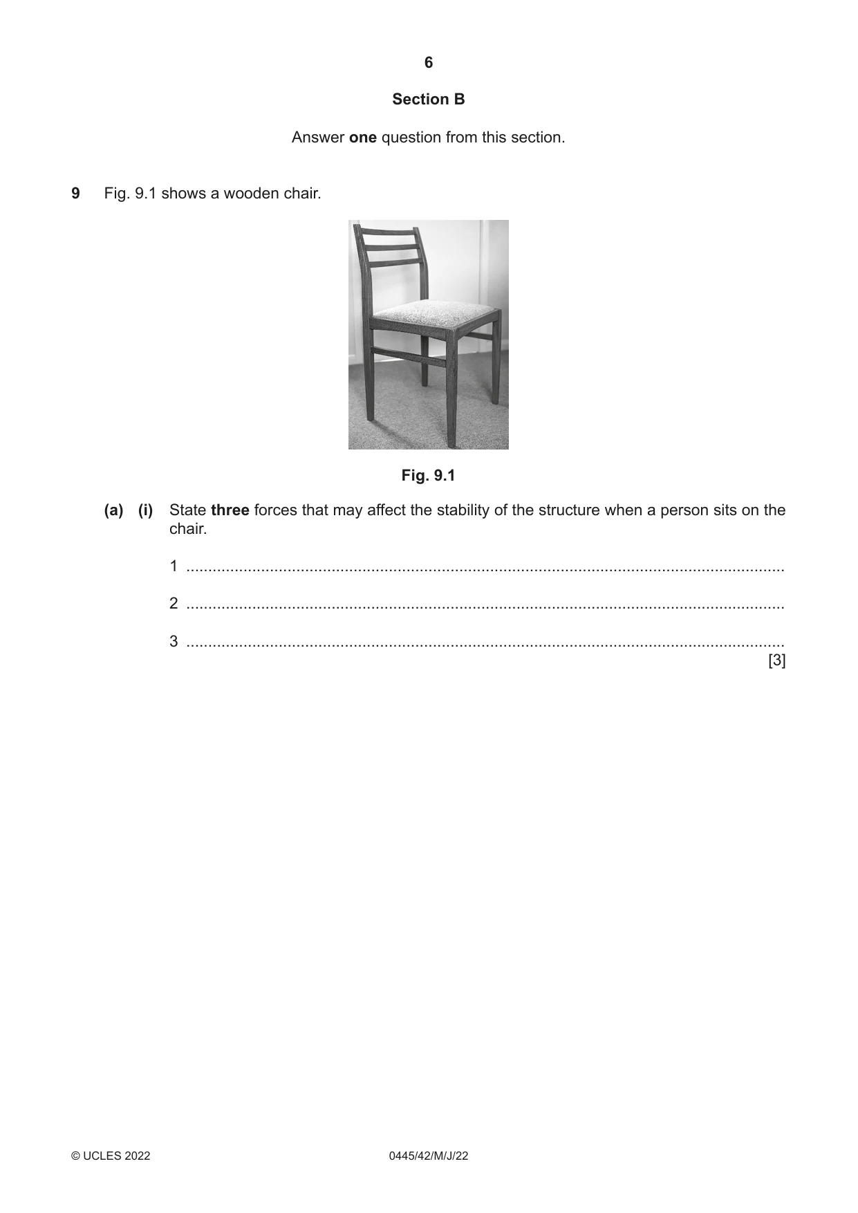
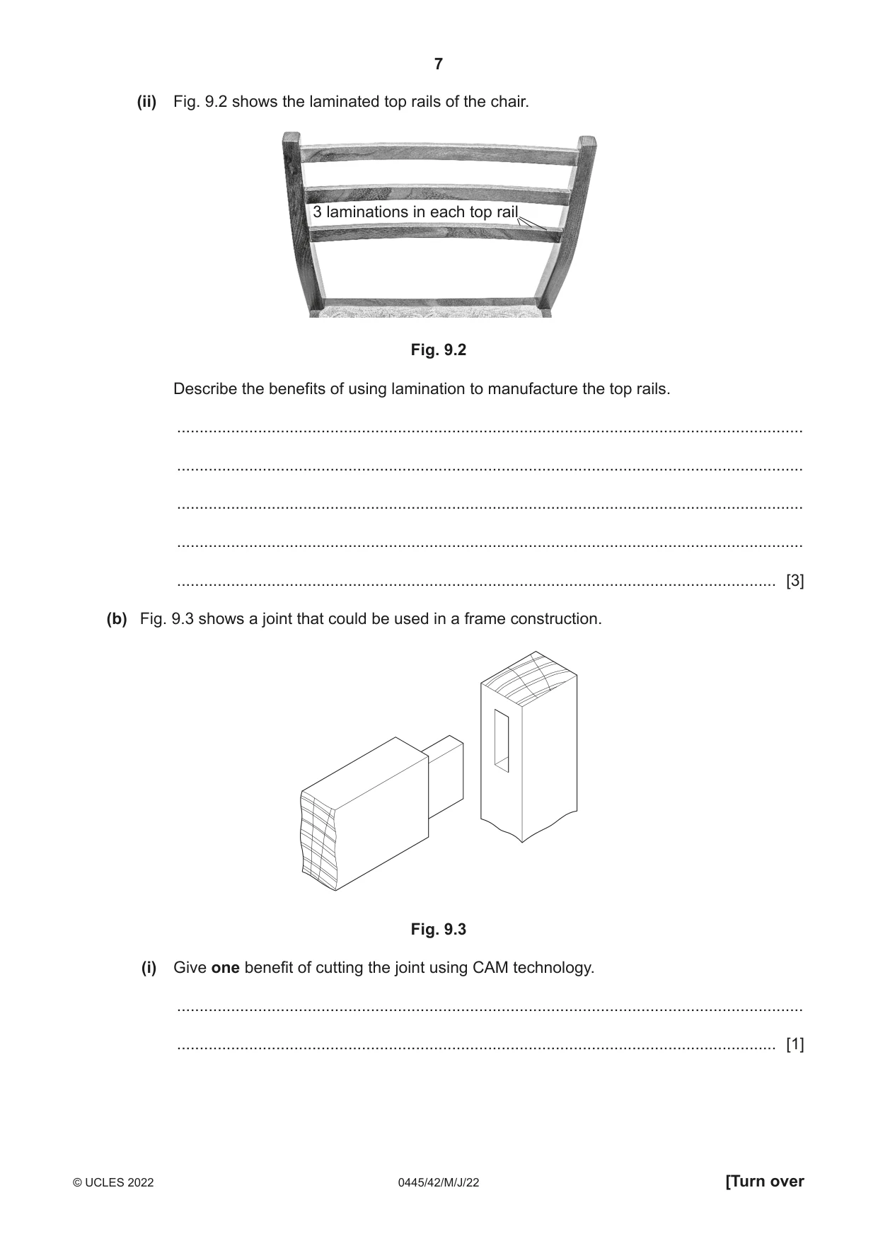
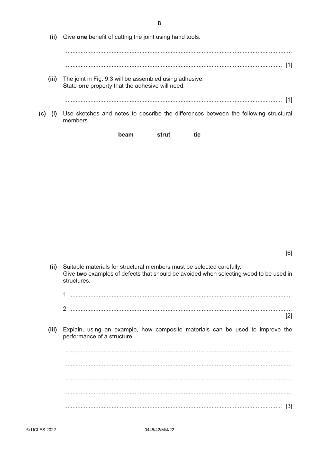
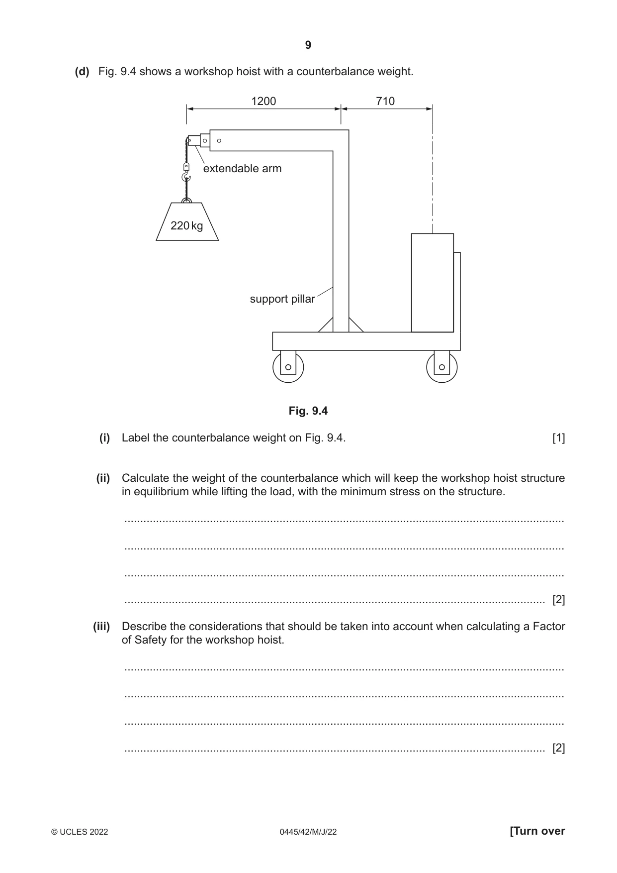
9 Fig. 9.1 shows a wooden chair. Fig. 9.1 (a) (i) State three forces that may affect the stability of the structure when a person sits on the chair. 1 ........................................................................................................................................ 2 ........................................................................................................................................ 3 ........................................................................................................................................ [3] (ii) Fig. 9.2 shows the laminated top rails of the chair. 3 laminations in each top rail Fig. 9.2 Describe the benefits of using lamination to manufacture the top rails. ........................................................................................................................................... ........................................................................................................................................... ........................................................................................................................................... ........................................................................................................................................... ..................................................................................................................................... [3] (b) Fig. 9.3 shows a joint that could be used in a frame construction. Fig. 9.3 (i) Give one benefit of cutting the joint using CAM technology. ........................................................................................................................................... ..................................................................................................................................... [1] (ii) Give one benefit of cutting the joint using hand tools. ........................................................................................................................................... ..................................................................................................................................... [1] (iii) The joint in Fig. 9.3 will be assembled using adhesive. State one property that the adhesive will need. ..................................................................................................................................... [1] (c) (i) Use sketches and notes to describe the differences between the following structural members. beam strut tie [6] (ii) Suitable materials for structural members must be selected carefully. Give two examples of defects that should be avoided when selecting wood to be used in structures. 1 ........................................................................................................................................ 2 ........................................................................................................................................ [2] (iii) Explain, using an example, how composite materials can be used to improve the performance of a structure. ........................................................................................................................................... ........................................................................................................................................... ........................................................................................................................................... ........................................................................................................................................... ..................................................................................................................................... [3] (d) Fig. 9.4 shows a workshop hoist with a counterbalance weight. 1200 710 extendable arm 220 kg support pillar Fig. 9.4 (i) Label the counterbalance weight on Fig. 9.4. [1] (ii) Calculate the weight of the counterbalance which will keep the workshop hoist structure in equilibrium while lifting the load, with the minimum stress on the structure. ........................................................................................................................................... ........................................................................................................................................... ........................................................................................................................................... ..................................................................................................................................... [2] (iii) Describe the considerations that should be taken into account when calculating a Factor of Safety for the workshop hoist. ........................................................................................................................................... ........................................................................................................................................... ........................................................................................................................................... ..................................................................................................................................... [2]
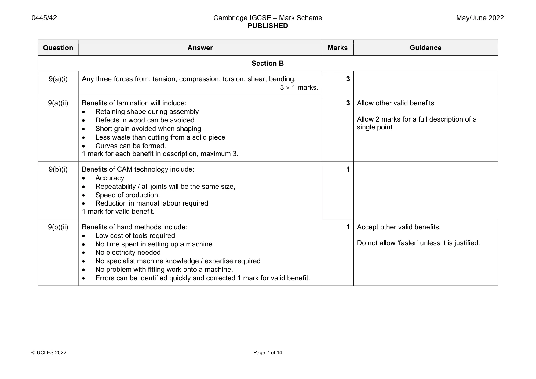
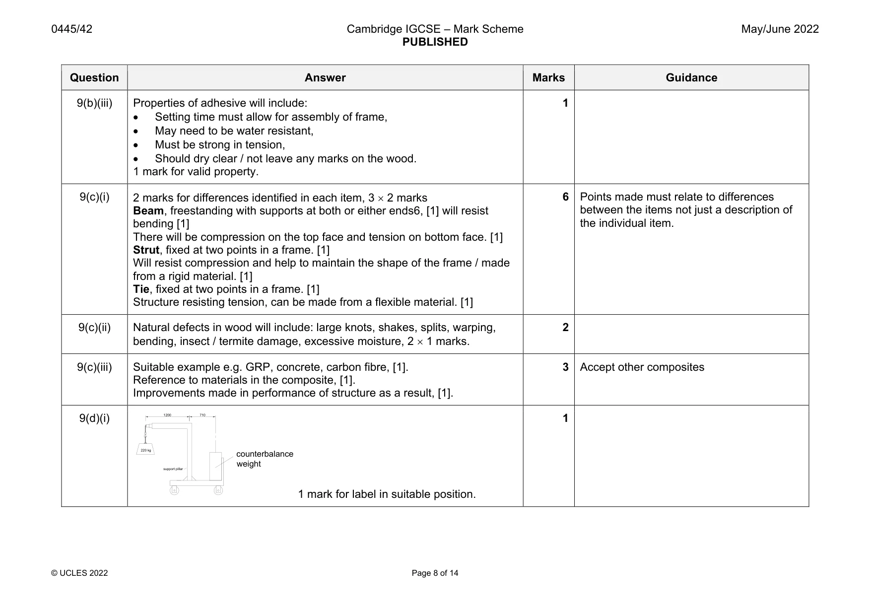
Mark scheme: 9(a)(i) Any three forces from: tension, compression, torsion, shear, bending, 3 1 marks. 3 9(a)(ii) Benefits of lamination will include: Retaining shape during assembly Defects in wood can be avoided Short grain avoided when shaping Less waste than cutting from a solid piece Curves can be formed. 1 mark for each benefit in description, maximum 3. 3 Allow other valid benefits Allow 2 marks for a full description of a single point. 9(b)(i) Benefits of CAM technology include: Accuracy Repeatability / all joints will be the same size, Speed of production. Reduction in manual labour required 1 mark for valid benefit. 1 9(b)(ii) Benefits of hand methods include: Low cost of tools required No time spent in setting up a machine No electricity needed No specialist machine knowledge / expertise required No problem with fitting work onto a machine. Errors can be identified quickly and corrected 1 mark for valid benefit. 1 Accept other valid benefits. Do not allow ‘faster’ unless it is justified. Question Answer Marks Guidance 9(b)(iii) Properties of adhesive will include: Setting time must allow for assembly of frame, May need to be water resistant, Must be strong in tension, Should dry clear / not leave any marks on the wood. 1 mark for valid property. 1 9(c)(i) 2 marks for differences identified in each item, 3 2 marks Beam, freestanding with supports at both or either ends6, [1] will resist bending [1] There will be compression on the top face and tension on bottom face. [1] Strut, fixed at two points in a frame. [1] Will resist compression and help to maintain the shape of the frame / made from a rigid material. [1] Tie, fixed at two points in a frame. [1] Structure resisting tension, can be made from a flexible material. [1] 6 Points made must relate to differences between the items not just a description of the individual item. 9(c)(ii) Natural defects in wood will include: large knots, shakes, splits, warping, bending, insect / termite damage, excessive moisture, 2 1 marks. 2 9(c)(iii) Suitable example e.g. GRP, concrete, carbon fibre, [1]. Reference to materials in the composite, [1]. Improvements made in performance of structure as a result, [1]. 3 Accept other composites 9(d)(i) 1 mark for label in suitable position. 1 1200 710 support pillar 220 kg counterbalance weight Question Answer Marks Guidance 9(d)(ii) 220 1200 = 710 counterbalance, [1]. 220 1200 / 710 = 371.8 kg, [1]. 2 Award 2 marks for correct answer with no working. Allow rounding errors, e.g. 374 kg. 9(d)(iii) Factors to be considered will include: How far can the lifting arm be extended? The breaking strain of the lift cable Strength of the materials used Labelling on hoist to inform user of safe working loads Percentage reduction from the absolute maximum that can be lifted. 2 1 mark each for 2 points mentioned. Allow 2 marks for a single point fully explained / justified.
Q10 · Three methods of transmitting motion from one shaft to another
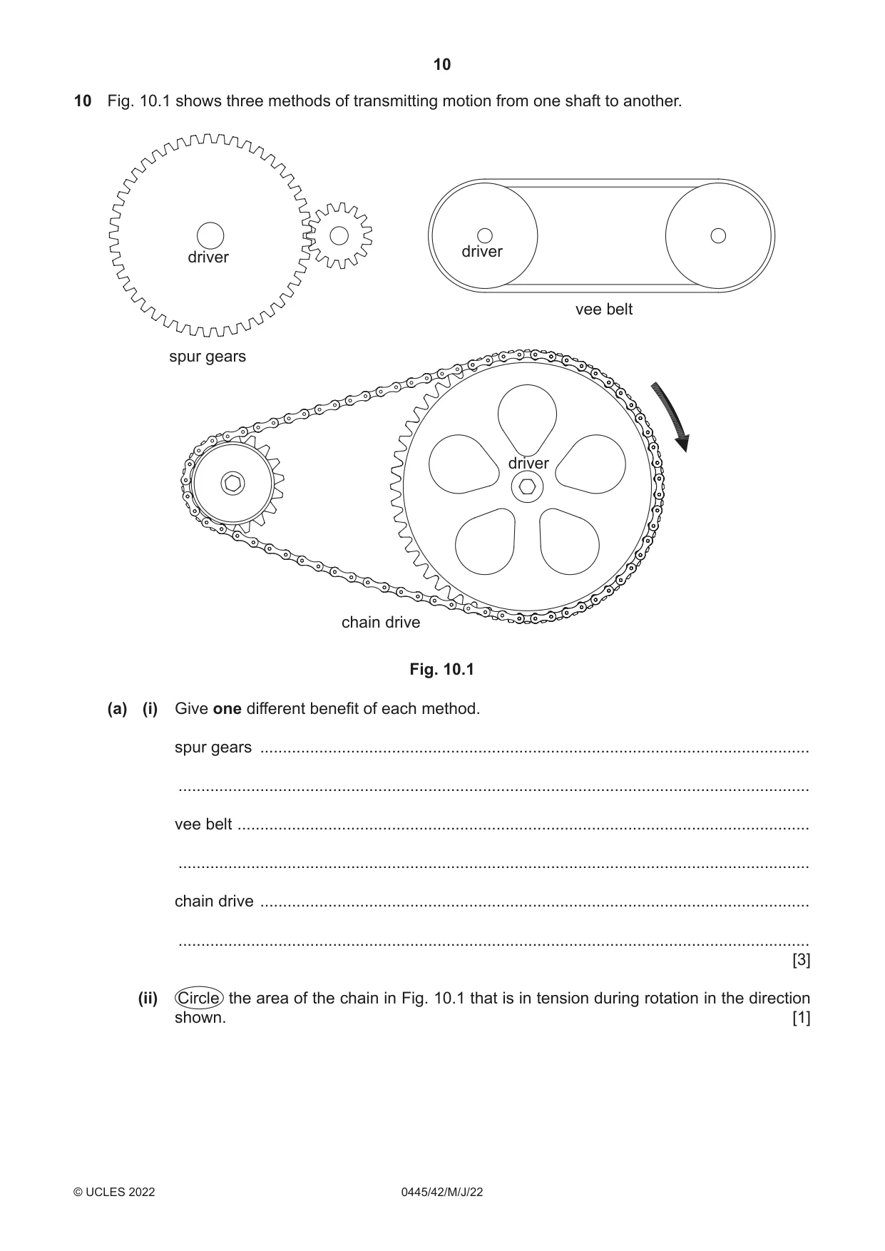
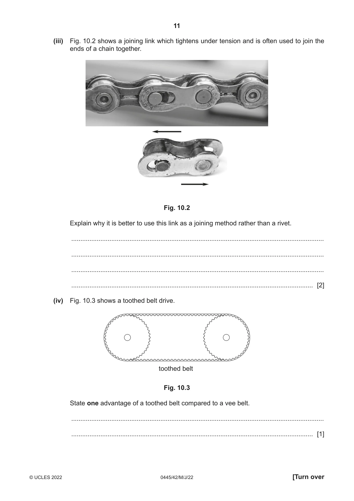
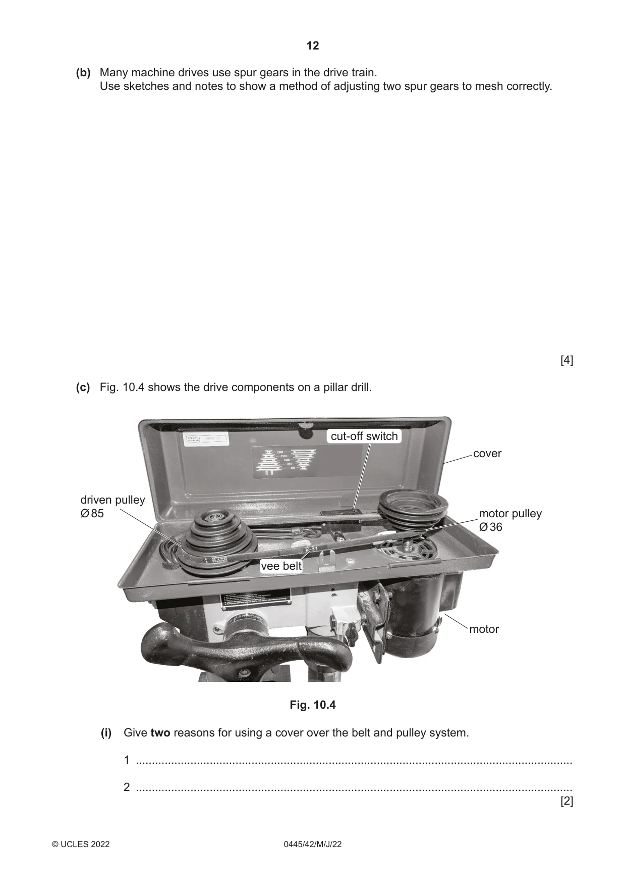
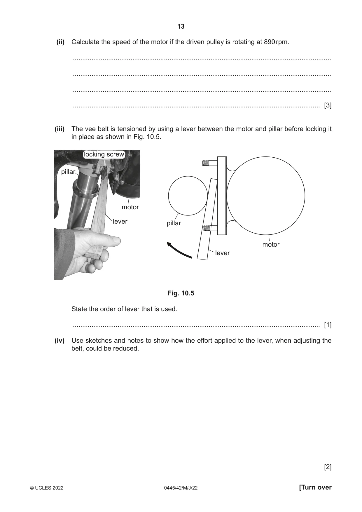
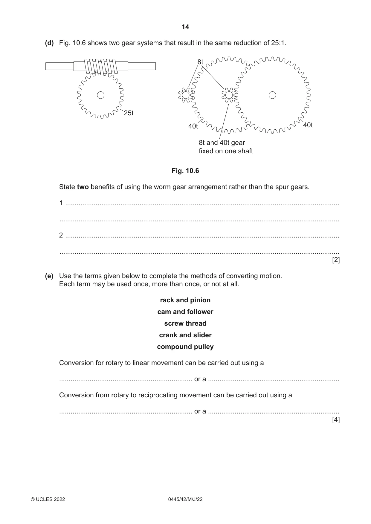
10 Fig. 10.1 shows three methods of transmitting motion from one shaft to another. driver driver vee belt spur gears driver chain drive Fig. 10.1 (a) (i) Give one different benefit of each method. spur gears ......................................................................................................................... ........................................................................................................................................... vee belt .............................................................................................................................. ........................................................................................................................................... chain drive ......................................................................................................................... ........................................................................................................................................... [3] (ii) Circle the area of the chain in Fig. 10.1 that is in tension during rotation in the direction shown. [1] (iii) Fig. 10.2 shows a joining link which tightens under tension and is often used to join the ends of a chain together. Fig. 10.2 Explain why it is better to use this link as a joining method rather than a rivet. ........................................................................................................................................... ........................................................................................................................................... ........................................................................................................................................... ..................................................................................................................................... [2] (iv) Fig. 10.3 shows a toothed belt drive. toothed belt Fig. 10.3 State one advantage of a toothed belt compared to a vee belt. ........................................................................................................................................... ..................................................................................................................................... [1] (b) Many machine drives use spur gears in the drive train. Use sketches and notes to show a method of adjusting two spur gears to mesh correctly. [4] (c) Fig. 10.4 shows the drive components on a pillar drill. cut-off switch cover driven pulley Ø 85 motor pulley Ø 36 vee belt motor Fig. 10.4 (i) Give two reasons for using a cover over the belt and pulley system. 1 ........................................................................................................................................ 2 ........................................................................................................................................ [2] (ii) Calculate the speed of the motor if the driven pulley is rotating at 890 rpm. ........................................................................................................................................... ........................................................................................................................................... ........................................................................................................................................... ..................................................................................................................................... [3] (iii) The vee belt is tensioned by using a lever between the motor and pillar before locking it in place as shown in Fig. 10.5. locking screw pillar motor lever pillar motor lever Fig. 10.5 State the order of lever that is used. ..................................................................................................................................... [1] (iv) Use sketches and notes to show how the effort applied to the lever, when adjusting the belt, could be reduced. [2] (d) Fig. 10.6 shows two gear systems that result in the same reduction of 25:1. 8t 25t 40t 40t 8t and 40t gear fixed on one shaft Fig. 10.6 State two benefits of using the worm gear arrangement rather than the spur gears. 1 ................................................................................................................................................ ................................................................................................................................................... 2 ................................................................................................................................................ ................................................................................................................................................... [2] (e) Use the terms given below to complete the methods of converting motion. Each term may be used once, more than once, or not at all. rack and pinion cam and follower screw thread crank and slider compound pulley Conversion for rotary to linear movement can be carried out using a ...................................................................... or a ..................................................................... Conversion from rotary to reciprocating movement can be carried out using a ...................................................................... or a ..................................................................... [4]
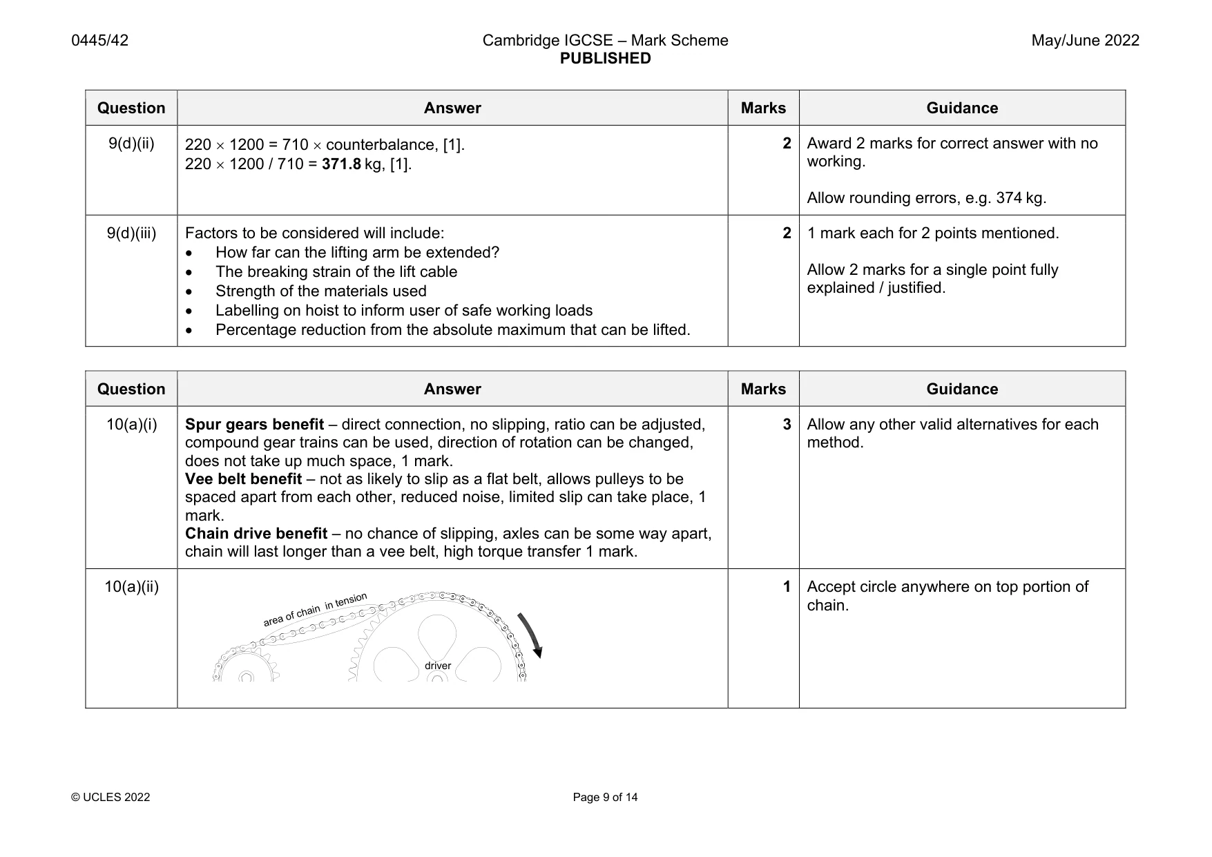
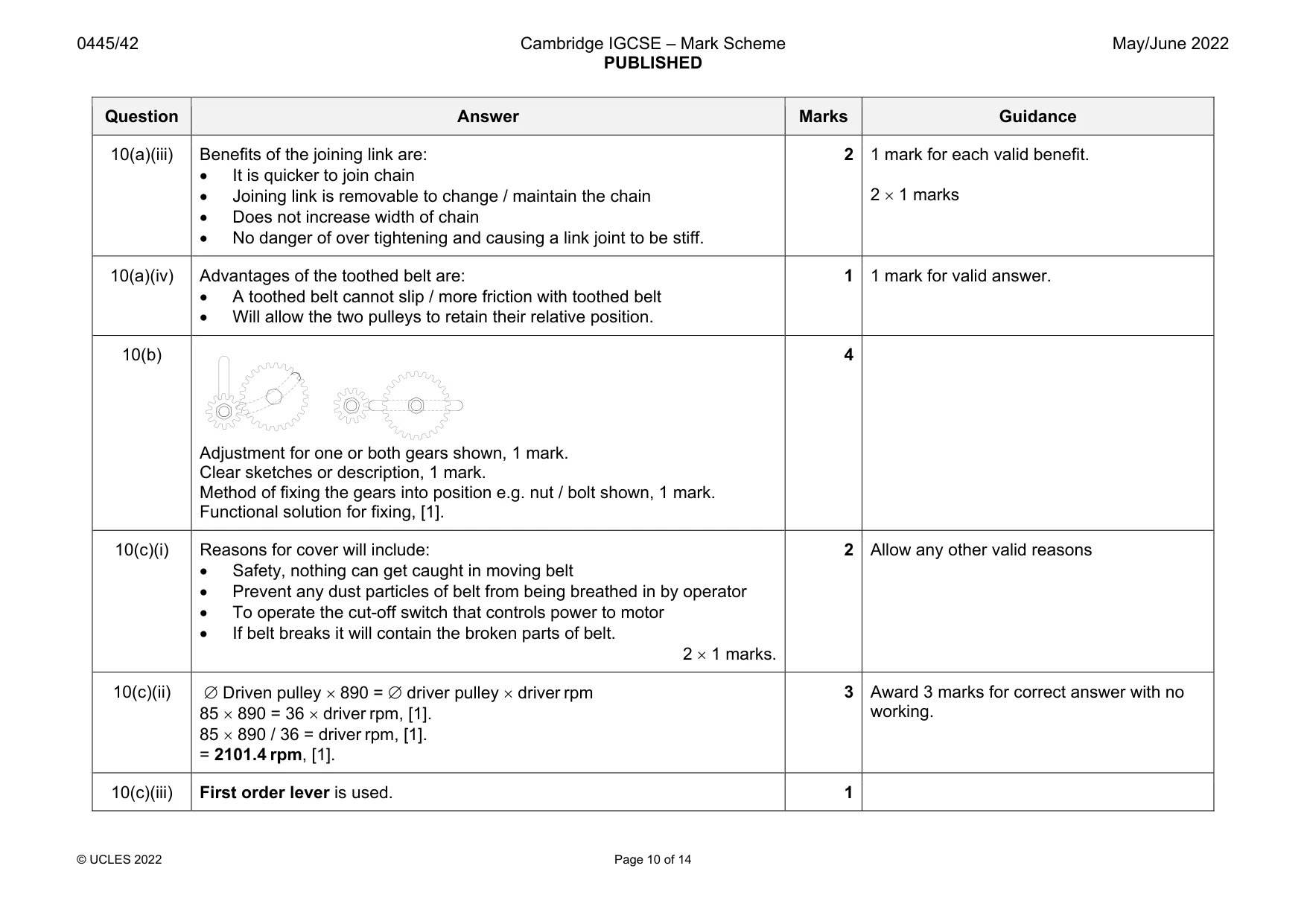
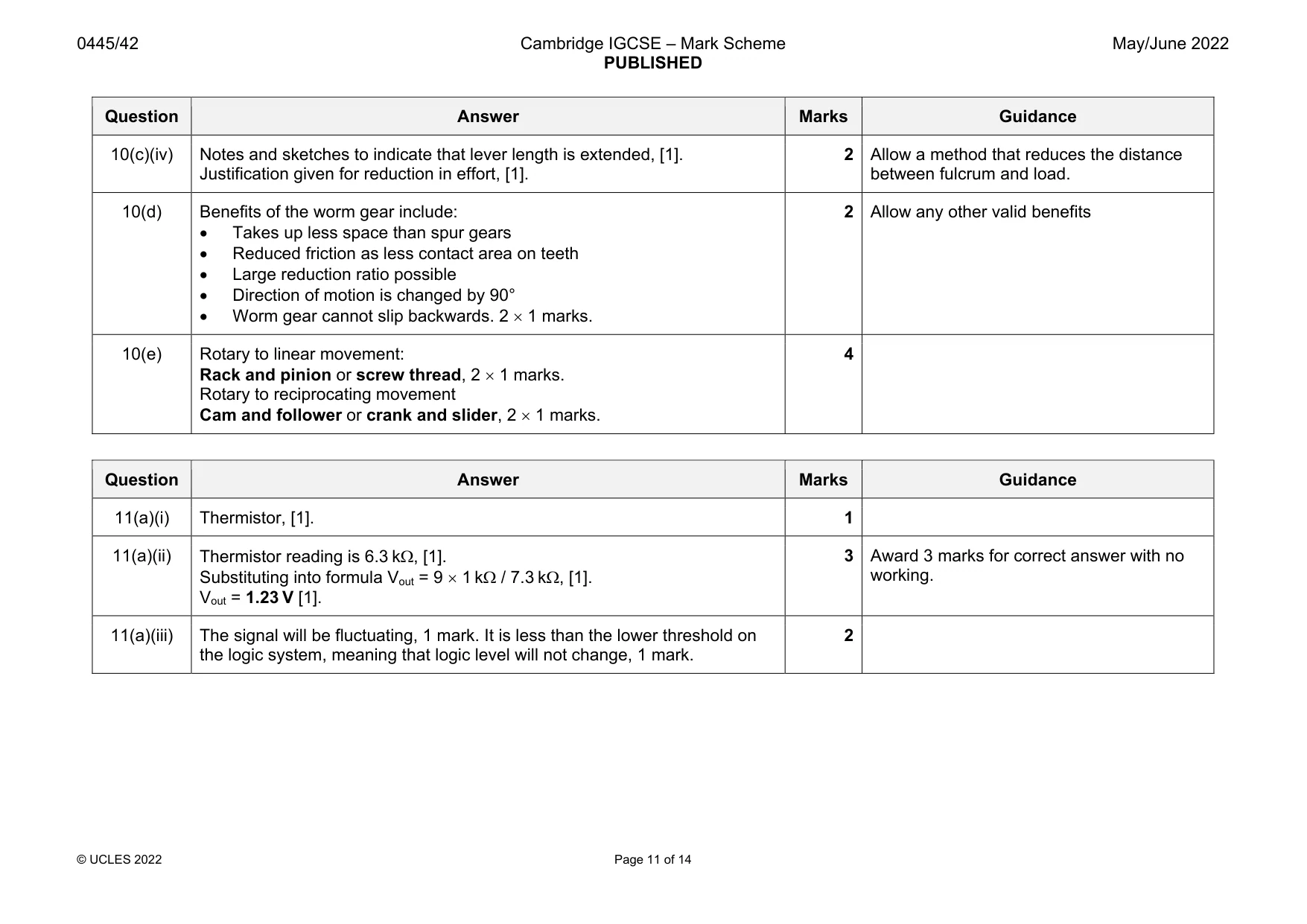
Mark scheme: 10(a)(i) Spur gears benefit – direct connection, no slipping, ratio can be adjusted, compound gear trains can be used, direction of rotation can be changed, does not take up much space, 1 mark. Vee belt benefit – not as likely to slip as a flat belt, allows pulleys to be spaced apart from each other, reduced noise, limited slip can take place, 1 mark. Chain drive benefit – no chance of slipping, axles can be some way apart, chain will last longer than a vee belt, high torque transfer 1 mark. method. 10(a)(ii) 1 Accept circle anywhere on top portion of chain. driver area of chain in tension Question Answer Marks Guidance 10(a)(iii) Benefits of the joining link are: It is quicker to join chain Joining link is removable to change / maintain the chain Does not increase width of chain No danger of over tightening and causing a link joint to be stiff. 2 1 mark for each valid benefit. 2 1 marks 10(a)(iv) Advantages of the toothed belt are: A toothed belt cannot slip / more friction with toothed belt Will allow the two pulleys to retain their relative position. 1 1 mark for valid answer. 10(b) Adjustment for one or both gears shown, 1 mark. Clear sketches or description, 1 mark. Method of fixing the gears into position e.g. nut / bolt shown, 1 mark. Functional solution for fixing, [1]. 4 10(c)(i) Reasons for cover will include: Safety, nothing can get caught in moving belt Prevent any dust particles of belt from being breathed in by operator To operate the cut-off switch that controls power to motor If belt breaks it will contain the broken parts of belt. 2 1 marks. 2 Allow any other valid reasons 10(c)(ii) Driven pulley 890 = driver pulley driver rpm 85 890 = 36 driver rpm, [1]. 85 890 / 36 = driver rpm, [1]. = 2101.4 rpm, [1]. 3 Award 3 marks for correct answer with no working. 10(c)(iii) First order lever is used. 1 Question Answer Marks Guidance 10(c)(iv) Notes and sketches to indicate that lever length is extended, [1]. Justification given for reduction in effort, [1]. 2 Allow a method that reduces the distance between fulcrum and load. 10(d) Benefits of the worm gear include: Takes up less space than spur gears Reduced friction as less contact area on teeth Large reduction ratio possible Direction of motion is changed by 90° Worm gear cannot slip backwards. 2 1 marks. 2 Allow any other valid benefits 10(e) Rotary to linear movement: Rack and pinion or screw thread, 2 1 marks. Rotary to reciprocating movement Cam and follower or crank and slider, 2 1 marks. 4
Q11 · A temperature sensing transducer to be used in a controller for a cooling fan
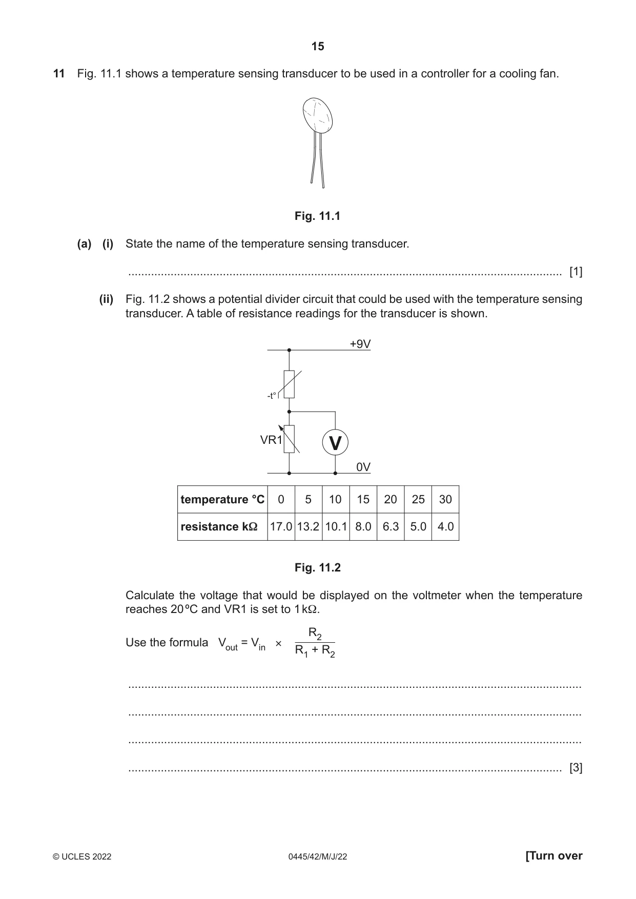
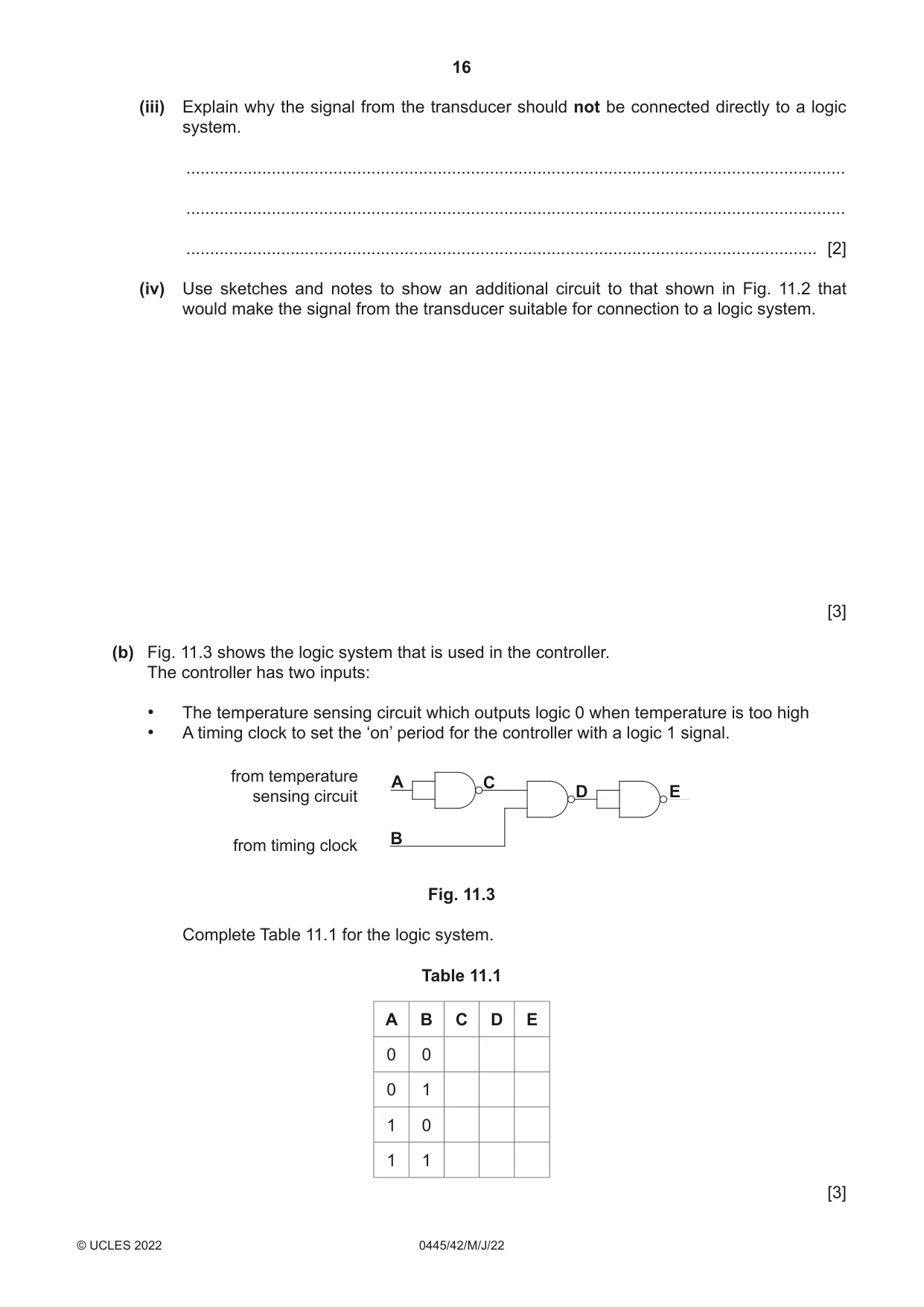
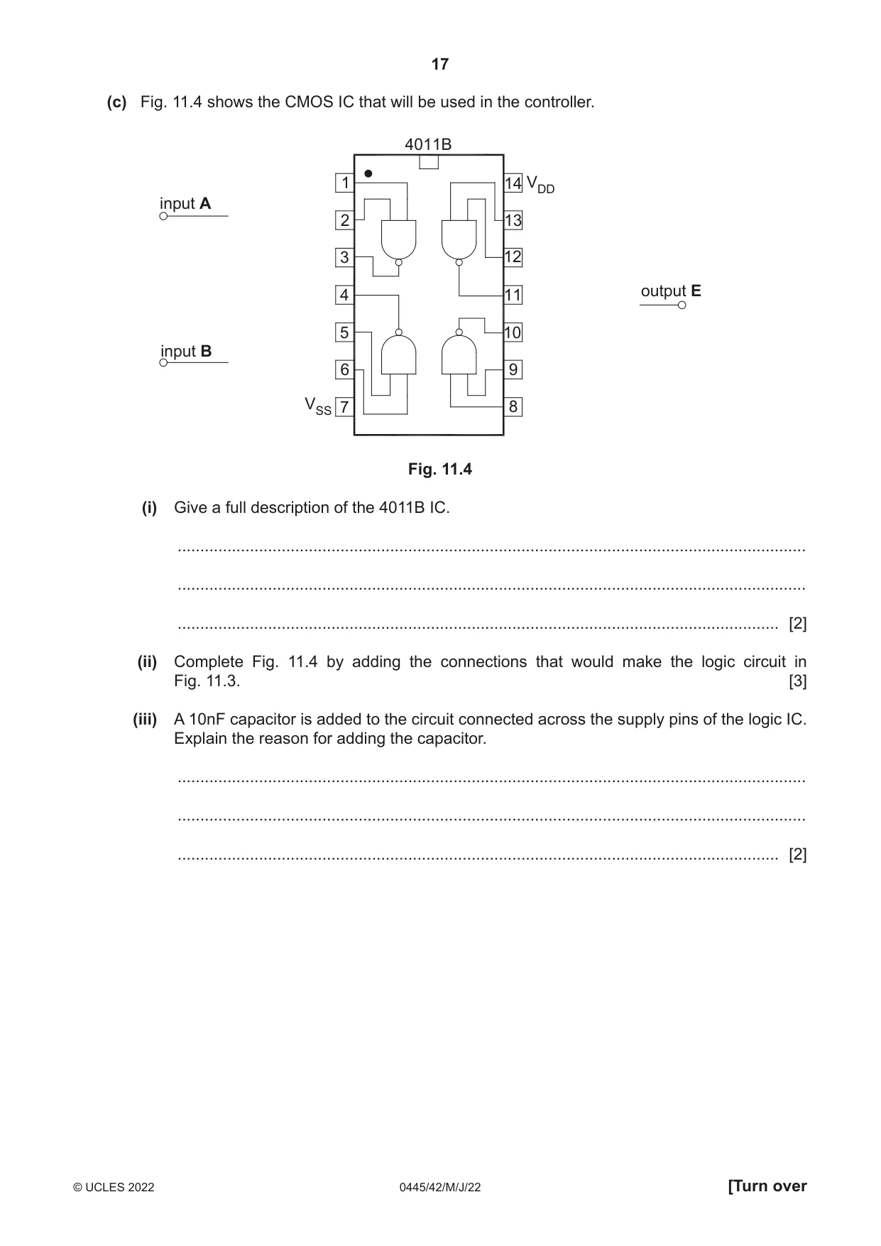
11 Fig. 11.1 shows a temperature sensing transducer to be used in a controller for a cooling fan. Fig. 11.1 (a) (i) State the name of the temperature sensing transducer. ..................................................................................................................................... [1] (ii) Fig. 11.2 shows a potential divider circuit that could be used with the temperature sensing transducer. A table of resistance readings for the transducer is shown. +9V -t° VR1 V 0V temperature °C 0 5 10 15 20 25 30 resistance kΩ 17.0 13.2 10.1 8.0 6.3 5.0 4.0 Fig. 11.2 Calculate the voltage that would be displayed on the voltmeter when the temperature reaches 20 ºC and VR1 is set to 1 kΩ. R2 Use the formula Vout = Vin × R1 + R2 ........................................................................................................................................... ........................................................................................................................................... ........................................................................................................................................... ..................................................................................................................................... [3] (iii) Explain why the signal from the transducer should not be connected directly to a logic system. ........................................................................................................................................... ........................................................................................................................................... ..................................................................................................................................... [2] (iv) Use sketches and notes to show an additional circuit to that shown in Fig. 11.2 that would make the signal from the transducer suitable for connection to a logic system. [3] (b) Fig. 11.3 shows the logic system that is used in the controller. The controller has two inputs: • The temperature sensing circuit which outputs logic 0 when temperature is too high • A timing clock to set the ‘on’ period for the controller with a logic 1 signal. from temperature A C sensing circuit D E B from timing clock Fig. 11.3 Complete Table 11.1 for the logic system. Table 11.1 A B C D E 0 0 0 1 1 0 1 1 [3] (c) Fig. 11.4 shows the CMOS IC that will be used in the controller. 4011B 1 14 VDD input A 2 13 3 12 4 11 output E 5 10 input B 6 9 VSS 7 8 Fig. 11.4 (i) Give a full description of the 4011B IC. ........................................................................................................................................... ........................................................................................................................................... ..................................................................................................................................... [2] (ii) Complete Fig. 11.4 by adding the connections that would make the logic circuit in Fig. 11.3. [3] (iii) A 10nF capacitor is added to the circuit connected across the supply pins of the logic IC. Explain the reason for adding the capacitor. ........................................................................................................................................... ........................................................................................................................................... ..................................................................................................................................... [2]
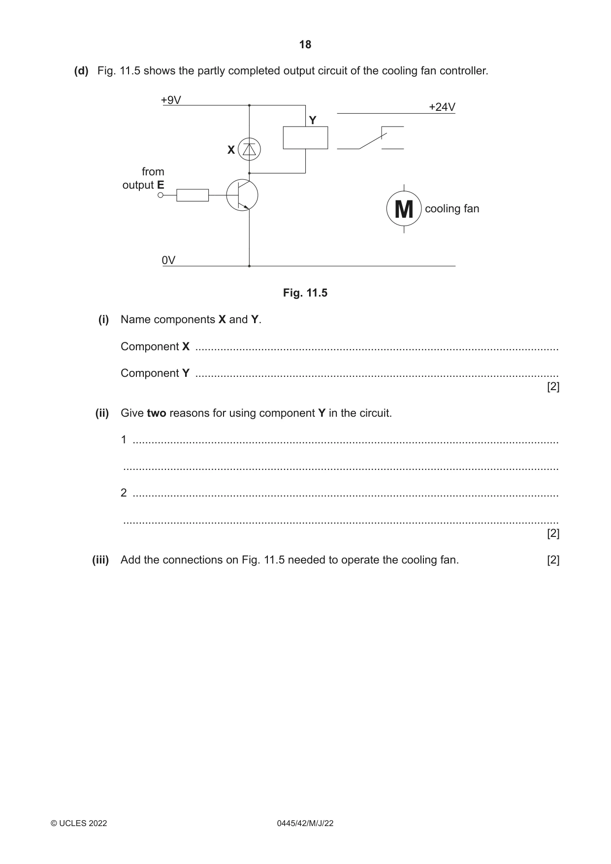
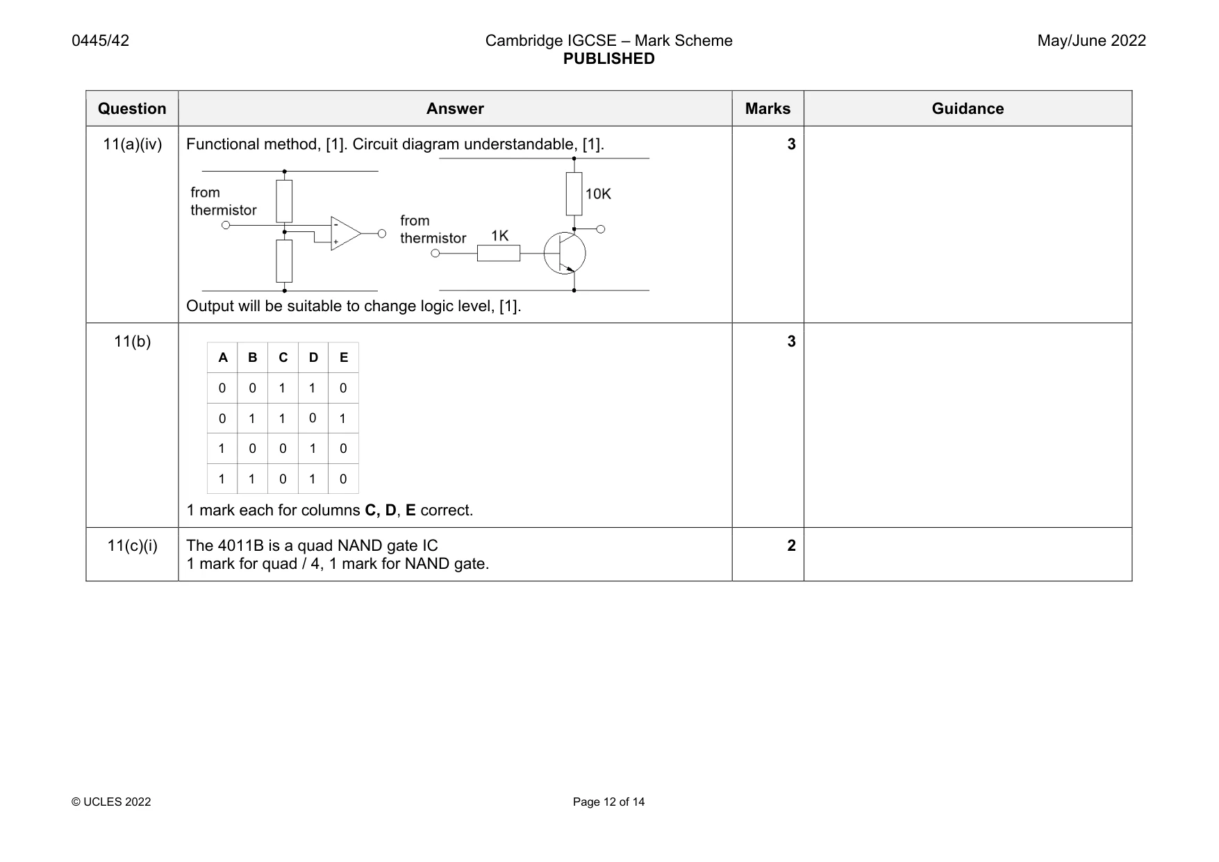
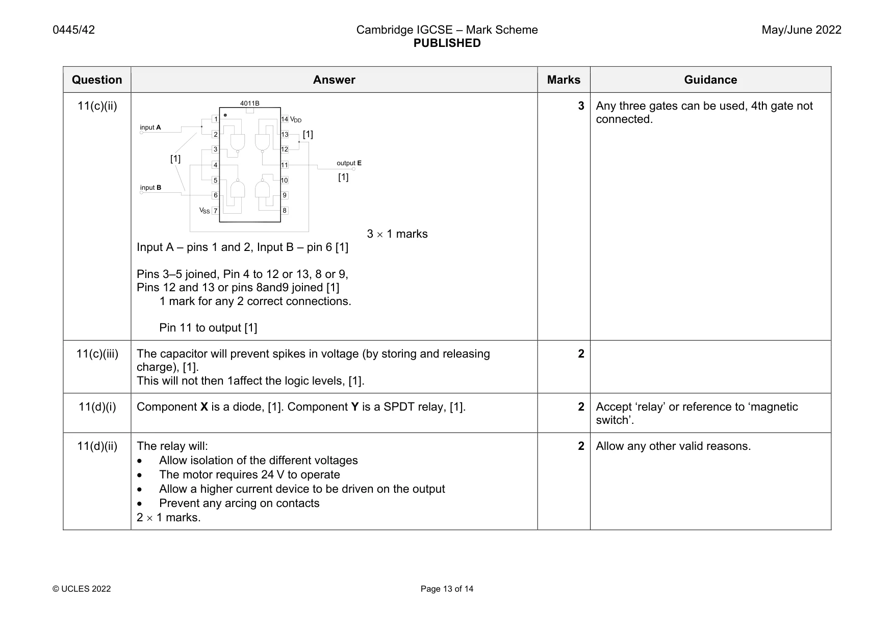
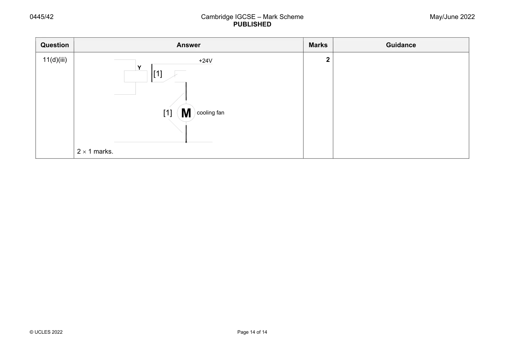
Mark scheme: 11(a)(i) Thermistor, [1]. 1 11(a)(ii) Thermistor reading is 6.3 k, [1]. Substituting into formula Vout = 9 1 k / 7.3 k, [1]. Vout = 1.23 V [1]. 3 Award 3 marks for correct answer with no working. 11(a)(iii) The signal will be fluctuating, 1 mark. It is less than the lower threshold on the logic system, meaning that logic level will not change, 1 mark. 2 Question Answer Marks Guidance 11(a)(iv) Functional method, [1]. Circuit diagram understandable, [1]. Output will be suitable to change logic level, [1]. 3 11(b) 1 mark each for columns C, D, E correct. 3 11(c)(i) The 4011B is a quad NAND gate IC 1 mark for quad / 4, 1 mark for NAND gate. 2 0 0 0 1 1 1 1 0 A B C D E 1 1 0 0 0 1 1 1 1 0 0 0 Question Answer Marks Guidance 11(c)(ii) 3 1 marks Input A – pins 1 and 2, Input B – pin 6 [1] Pins 3–5 joined, Pin 4 to 12 or 13, 8 or 9, Pins 12 and 13 or pins 8and9 joined [1] 1 mark for any 2 correct connections. Pin 11 to output [1] 3 Any three gates can be used, 4th gate not connected. 11(c)(iii) The capacitor will prevent spikes in voltage (by storing and releasing charge), [1]. This will not then 1affect the logic levels, [1]. 2 11(d)(i) Component X is a diode, [1]. Component Y is a SPDT relay, [1]. 2 Accept ‘relay’ or reference to ‘magnetic switch’. 11(d)(ii) The relay will: Allow isolation of the different voltages The motor requires 24 V to operate Allow a higher current device to be driven on the output Prevent any arcing on contacts 2 1 marks. 2 Allow any other valid reasons. 1 2 3 4 5 6 7 8 9 10 11 12 13 4011B 14 input A input B output E [1] [1] [1] Question Answer Marks Guidance 11(d)(iii) 2 1 marks. 2 M Y cooling fan +24V [1] [1]
What was in this paper
The subtopics covered by these 11 questions, and how many questions each got. Open one in a new tab to see every Cambridge question on it.
What you needed in this session
Cambridge’s own grade thresholds for 2022 May/June, Paper 4 · Variant 2. A higher threshold means an easier paper — the bar moves with how the cohort did.