Cambridge IGCSE Design and Technology 0445 — 2024 May/June Paper 4 · Variant 2
0445/42/M/J/24 · 12 questions · 50 marks · 60 min
The question paper and its mark scheme, free to read here and free to download. This is Cambridge’s own paper, exactly as it was sat.
Question paper20 pages
Mark scheme12 pages
Answers below. Sit the paper first if you are practising.
Questions as text
Q1 · Four examples of timber structures used in a building
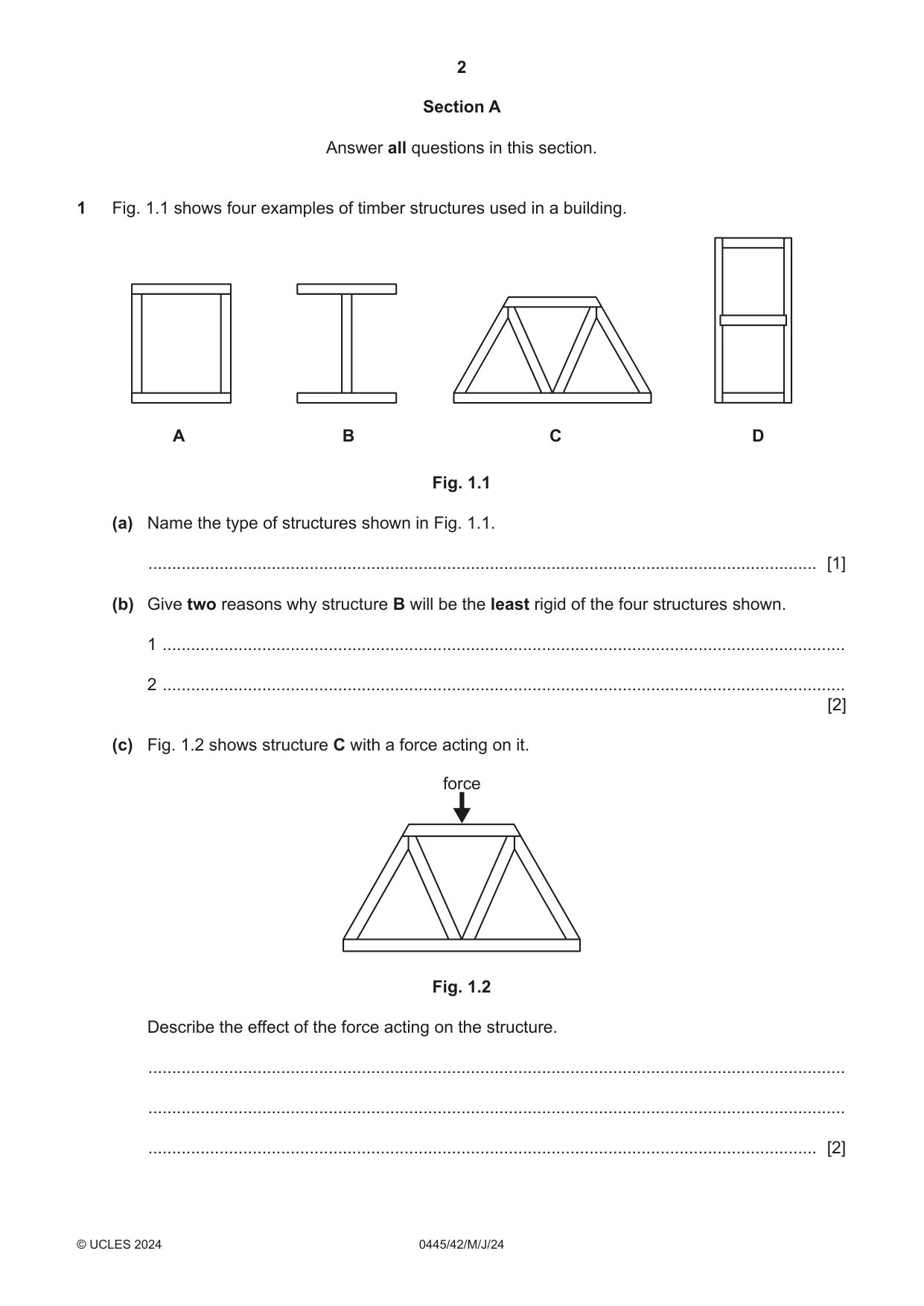
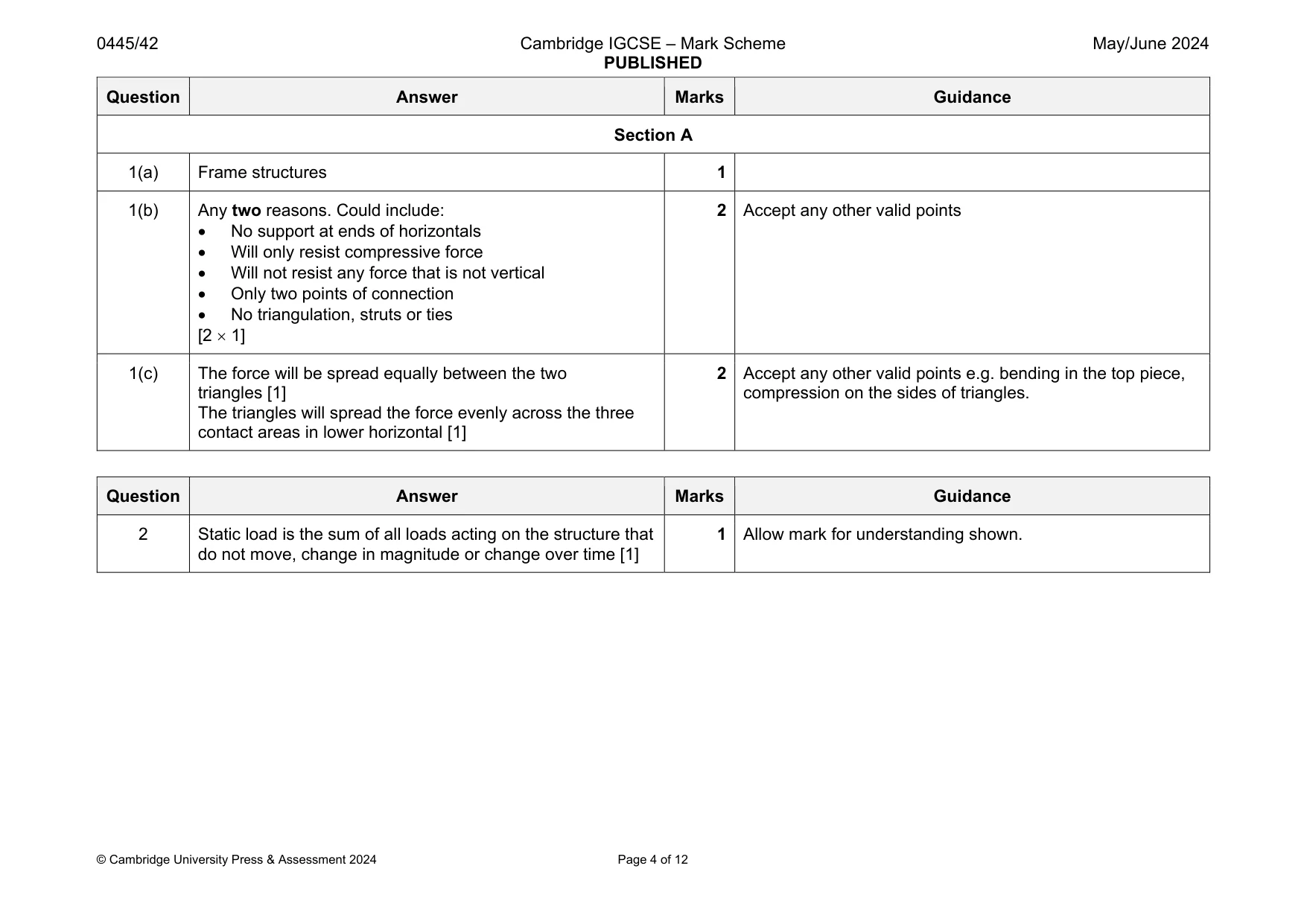
1 Fig. 1.1 shows four examples of timber structures used in a building. A B C D Fig. 1.1 (a) Name the type of structures shown in Fig. 1.1. ............................................................................................................................................. [1] (b) Give two reasons why structure B will be the least rigid of the four structures shown. 1 ................................................................................................................................................ 2 ................................................................................................................................................ [2] (c) Fig. 1.2 shows structure C with a force acting on it. force Fig. 1.2 Describe the effect of the force acting on the structure. ................................................................................................................................................... ................................................................................................................................................... ............................................................................................................................................. [2]
Mark scheme: 1(a) Frame structures 1 1(b) Any two reasons. Could include: No support at ends of horizontals Will only resist compressive force Will not resist any force that is not vertical Only two points of connection No triangulation, struts or ties [2 1] 2 Accept any other valid points 1(c) The force will be spread equally between the two triangles [1] The triangles will spread the force evenly across the three contact areas in lower horizontal [1] 2 Accept any other valid points e.g. bending in the top piece, compression on the sides of triangles.
Q2 · State the meaning of static load on a structure
2 State the meaning of static load on a structure. .................................................................................................................................................... [1]
Mark scheme: 2 Static load is the sum of all loads acting on the structure that do not move, change in magnitude or change over time [1] 1 Allow mark for understanding shown.
Q3 · A list of materials and properties is given below
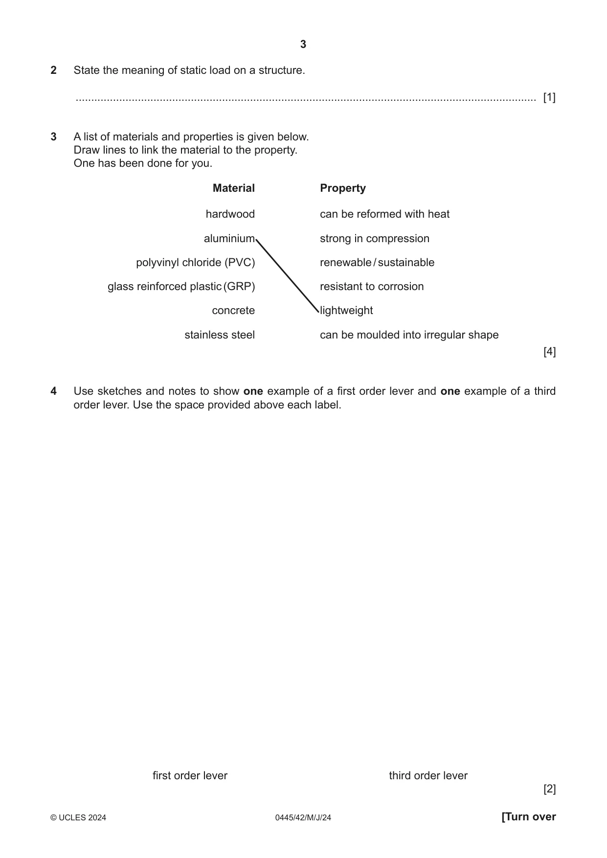
3 A list of materials and properties is given below. Draw lines to link the material to the property. One has been done for you. Material Property hardwood can be reformed with heat aluminium strong in compression polyvinyl chloride (PVC) renewable / sustainable glass reinforced plastic (GRP) resistant to corrosion concrete lightweight stainless steel can be moulded into irregular shape [4]
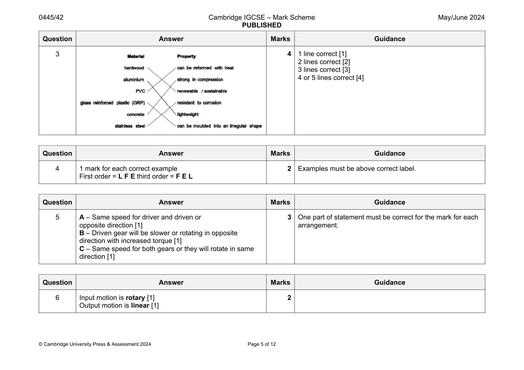
Mark scheme: 3 2 lines correct [2] 3 lines correct [3] 4 or 5 lines correct [4]
Q4 · Use sketches and notes to show one example of a first order lever and one example of a…
4 Use sketches and notes to show one example of a first order lever and one example of a third order lever. Use the space provided above each label. first order lever third order lever [2]
Mark scheme: 4 1 mark for each correct example First order = L F E third order = F E L 2 Examples must be above correct label.
Q5 · Three different arrangements of spur gears
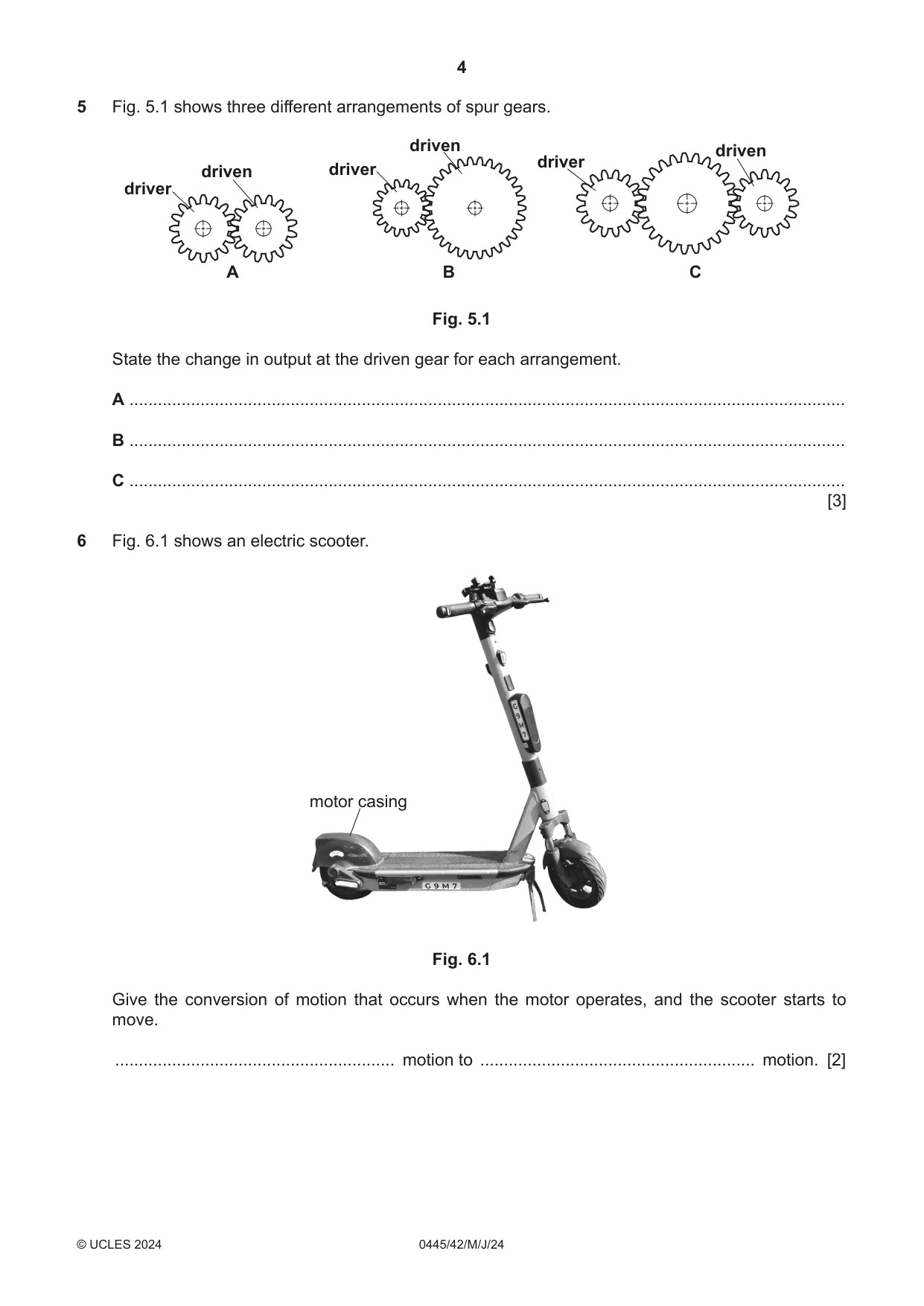
5 Fig. 5.1 shows three different arrangements of spur gears. driven driven driver driven driver driver A B C Fig. 5.1 State the change in output at the driven gear for each arrangement. A ....................................................................................................................................................... B ....................................................................................................................................................... C ....................................................................................................................................................... [3]
Mark scheme: 5 A – Same speed for driver and driven or opposite direction [1] B – Driven gear will be slower or rotating in opposite direction with increased torque [1] C – Same speed for both gears or they will rotate in same direction [1] arrangement.
Question 6
6 Fig. 6.1 shows an electric scooter. motor casing Fig. 6.1 Give the conversion of motion that occurs when the motor operates, and the scooter starts to move. ........................................................... motion to .......................................................... motion. [2]
Mark scheme: 6 Input motion is rotary [1] Output motion is linear [1] 2
Question 7
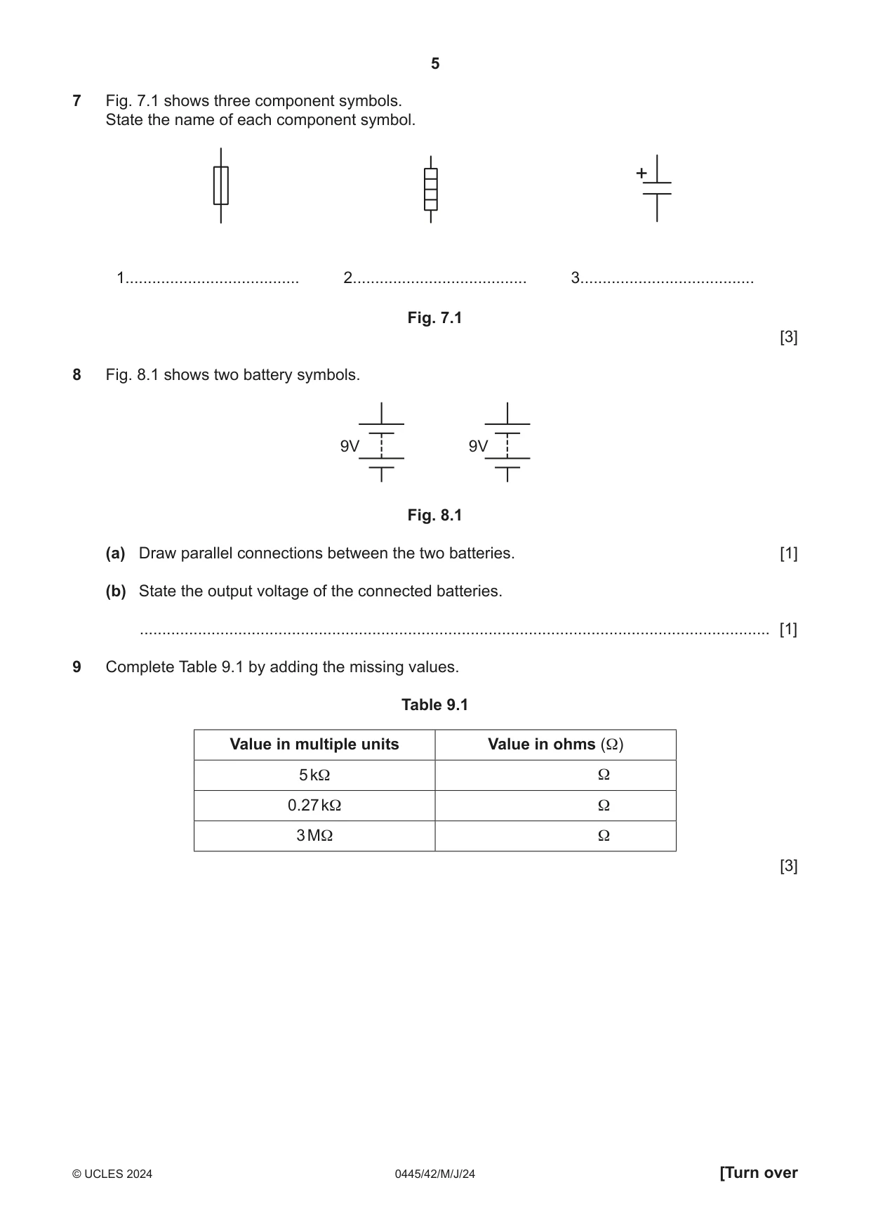
7 Fig. 7.1 shows three component symbols. State the name of each component symbol. + 1....................................... 2....................................... 3....................................... Fig. 7.1 [3]
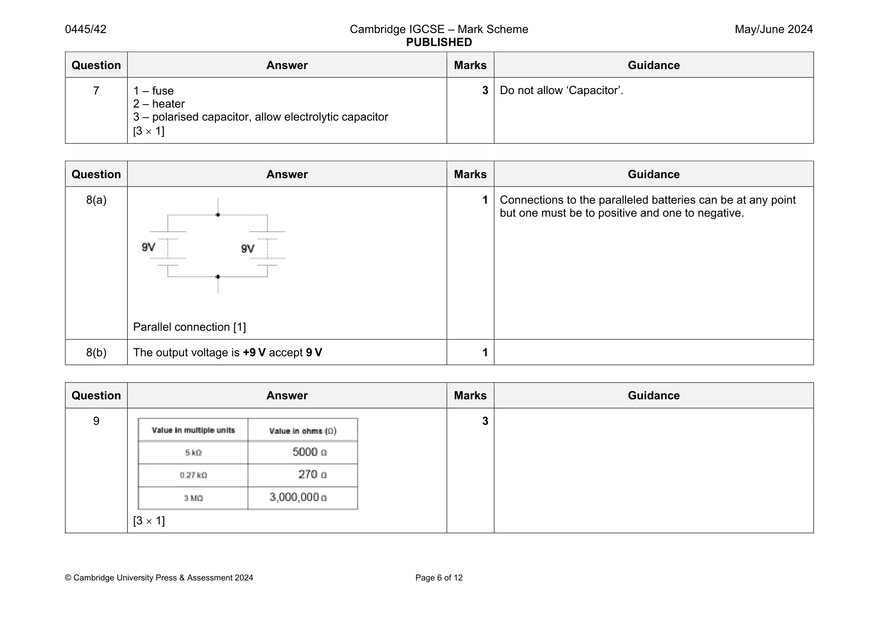
Mark scheme: 7 1 – fuse 2 – heater 3 – polarised capacitor, allow electrolytic capacitor [3 1]
Question 8
8 Fig. 8.1 shows two battery symbols. 9V 9V Fig. 8.1 (a) Draw parallel connections between the two batteries. [1] (b) State the output voltage of the connected batteries. ............................................................................................................................................. [1]
Mark scheme: 8(a) Parallel connection [1] 1 Connections to the paralleled batteries can be at any point but one must be to positive and one to negative. 8(b) The output voltage is +9 V accept 9 V 1
Q9 · Complete Table 9.1 by adding the missing values
9 Complete Table 9.1 by adding the missing values. Table 9.1 Value in multiple units Value in ohms (Ω) 5 kΩ Ω 0.27 kΩ Ω 3 MΩ Ω [3]
Mark scheme: 9 [3 1] 3
Q10 · Students have been set the task of designing a model suspension bridge to span a gap of…
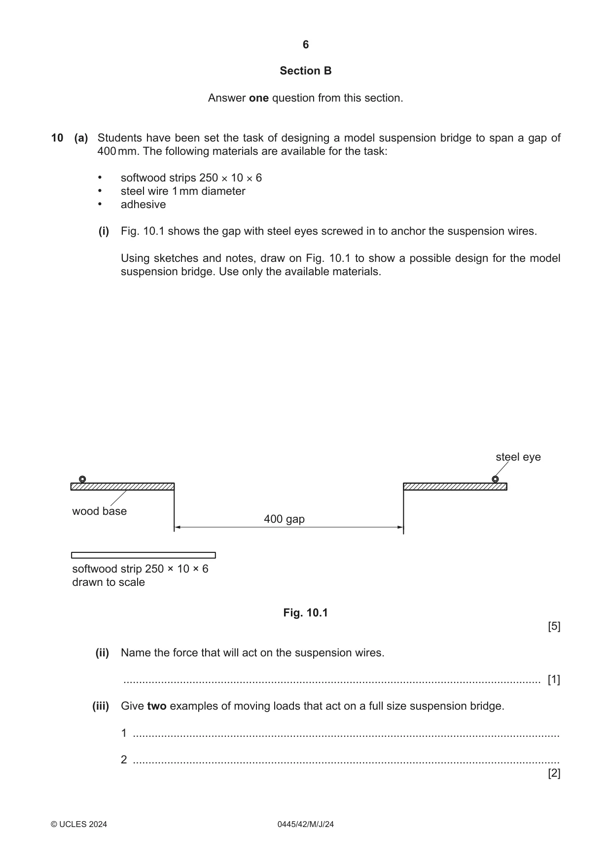
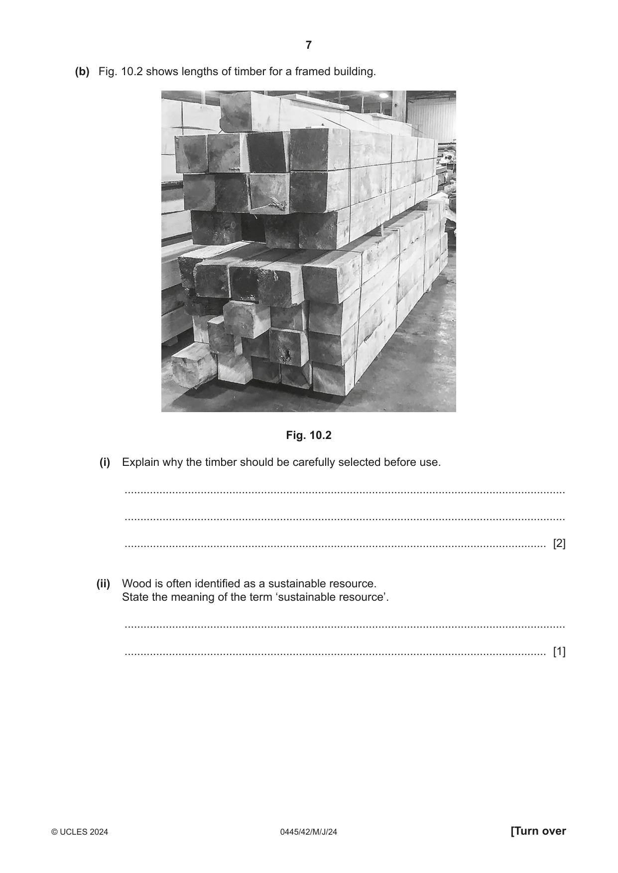
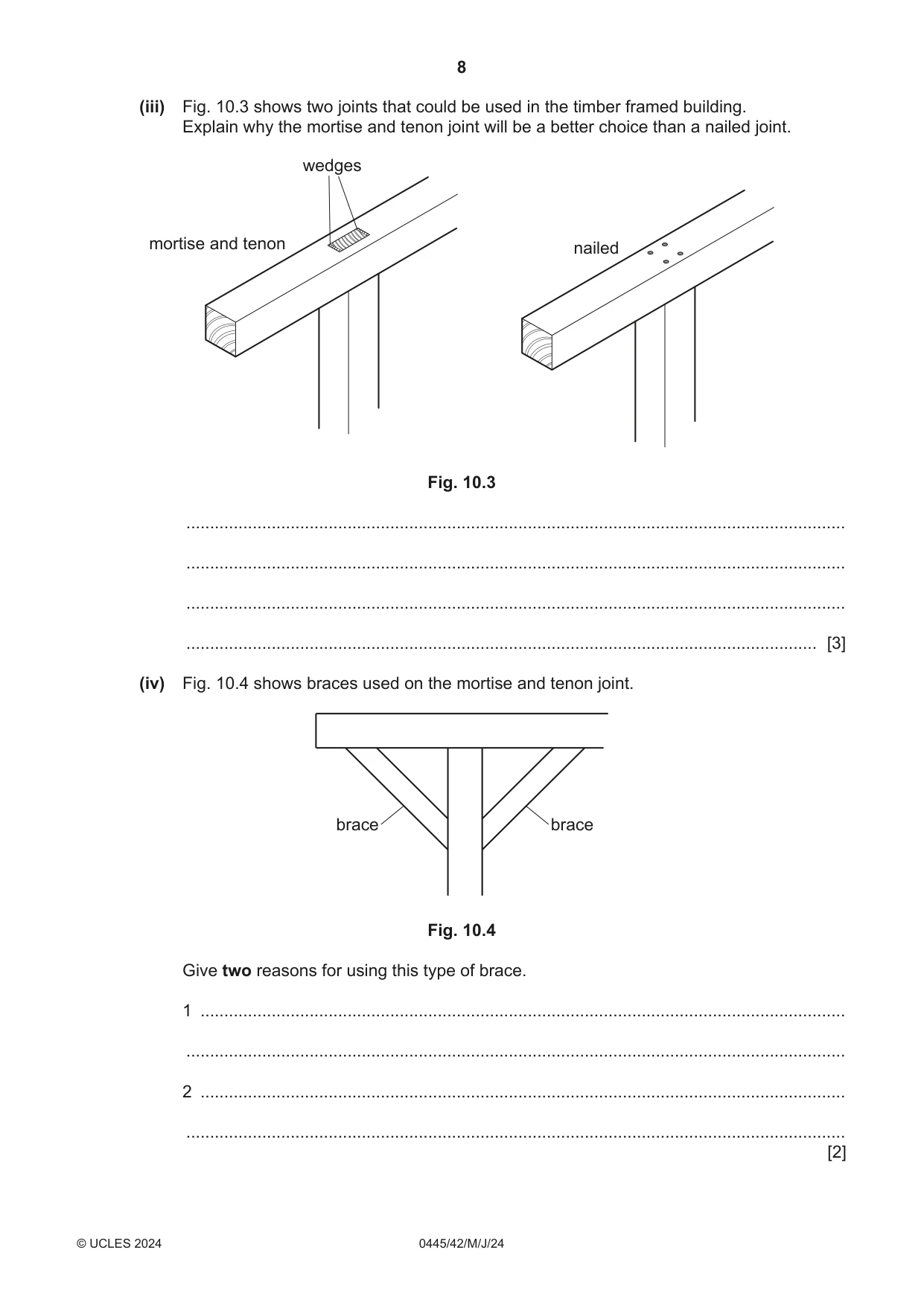
10 (a) Students have been set the task of designing a model suspension bridge to span a gap of 400 mm. The following materials are available for the task: • softwood strips 250 × 10 × 6 • steel wire 1 mm diameter • adhesive (i) Fig. 10.1 shows the gap with steel eyes screwed in to anchor the suspension wires. Using sketches and notes, draw on Fig. 10.1 to show a possible design for the model suspension bridge. Use only the available materials. steel eye wood base 400 gap softwood strip 250 × 10 × 6 drawn to scale Fig. 10.1 [5] (ii) Name the force that will act on the suspension wires. ..................................................................................................................................... [1] (iii) Give two examples of moving loads that act on a full size suspension bridge. 1 ........................................................................................................................................ 2 ........................................................................................................................................ [2] (b) Fig. 10.2 shows lengths of timber for a framed building. Fig. 10.2 (i) Explain why the timber should be carefully selected before use. ........................................................................................................................................... ........................................................................................................................................... ..................................................................................................................................... [2] (ii) Wood is often identified as a sustainable resource. State the meaning of the term ‘sustainable resource’. ........................................................................................................................................... ..................................................................................................................................... [1] (iii) Fig. 10.3 shows two joints that could be used in the timber framed building. Explain why the mortise and tenon joint will be a better choice than a nailed joint. wedges mortise and tenon nailed Fig. 10.3 ........................................................................................................................................... ........................................................................................................................................... ........................................................................................................................................... ..................................................................................................................................... [3] (iv) Fig. 10.4 shows braces used on the mortise and tenon joint. brace brace Fig. 10.4 Give two reasons for using this type of brace. 1 ........................................................................................................................................ ........................................................................................................................................... 2 ........................................................................................................................................ ........................................................................................................................................... [2] (c) Use sketches and notes to show what is meant by the following structural members. (i) Strut [2] (ii) Tie [2] (iii) Name the forces resisted by a strut and a tie. Force resisted by a strut .................................................................................................... Force resisted by a tie ....................................................................................................... [2] (d) Calculate the stress on a steel rod made of 9 mm diameter wire when a force of 1750 N is applied to it. ................................................................................................................................................... ................................................................................................................................................... ................................................................................................................................................... ............................................................................................................................................. [3]
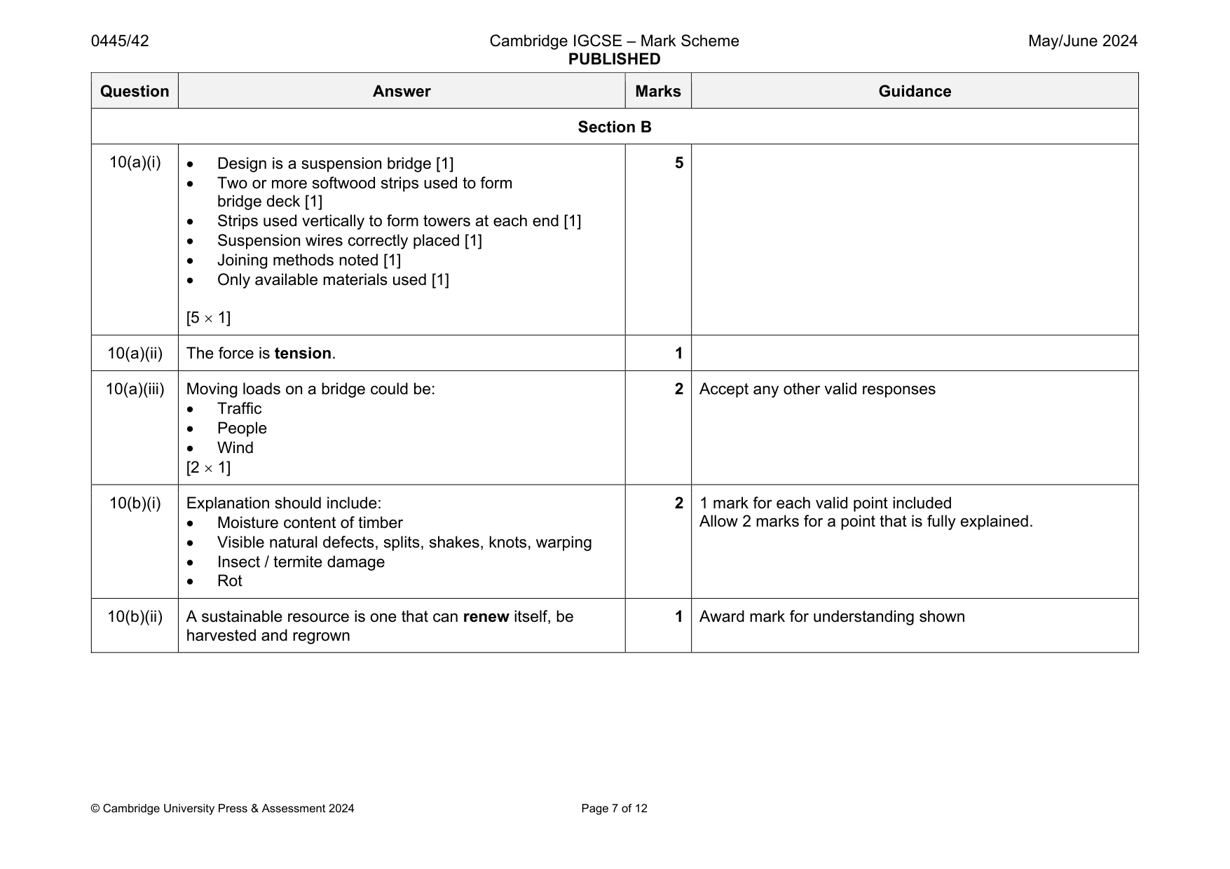
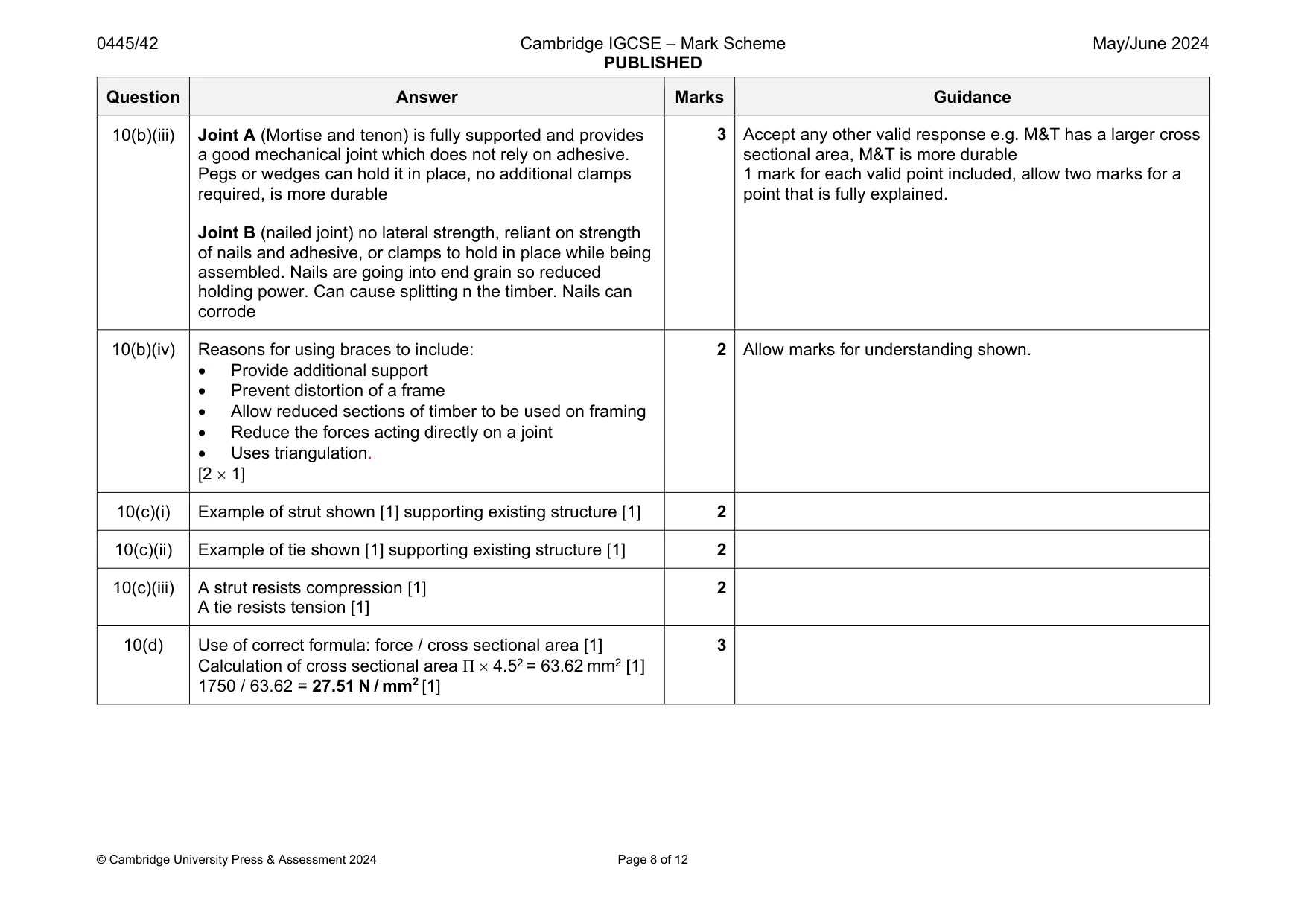
Mark scheme: 10(a)(i) Design is a suspension bridge [1] Two or more softwood strips used to form bridge deck [1] Strips used vertically to form towers at each end [1] Suspension wires correctly placed [1] Joining methods noted [1] Only available materials used [1] [5 1] 5 10(a)(ii) The force is tension. 1 10(a)(iii) Moving loads on a bridge could be: Traffic People Wind [2 1] 2 Accept any other valid responses 10(b)(i) Explanation should include: Moisture content of timber Visible natural defects, splits, shakes, knots, warping Insect / termite damage Rot 2 1 mark for each valid point included Allow 2 marks for a point that is fully explained. 10(b)(ii) A sustainable resource is one that can renew itself, be harvested and regrown 1 Award mark for understanding shown Question Answer Marks Guidance 10(b)(iii) Joint A (Mortise and tenon) is fully supported and provides a good mechanical joint which does not rely on adhesive. Pegs or wedges can hold it in place, no additional clamps required, is more durable Joint B (nailed joint) no lateral strength, reliant on strength of nails and adhesive, or clamps to hold in place while being assembled. Nails are going into end grain so reduced holding power. Can cause splitting n the timber. Nails can corrode 3 Accept any other valid response e.g. M&T has a larger cross sectional area, M&T is more durable 1 mark for each valid point included, allow two marks for a point that is fully explained. 10(b)(iv) Reasons for using braces to include: Provide additional support Prevent distortion of a frame Allow reduced sections of timber to be used on framing Reduce the forces acting directly on a joint Uses triangulation. [2 1] 2 Allow marks for understanding shown. 10(c)(i) Example of strut shown [1] supporting existing structure [1] 2 10(c)(ii) Example of tie shown [1] supporting existing structure [1] 2 10(c)(iii) A strut resists compression [1] A tie resists tension [1] 2 10(d) Use of correct formula: force / cross sectional area [1] Calculation of cross sectional area Π 4.52 = 63.62 mm2 [1] 1750 / 63.62 = 27.51 N / mm2 [1] 3
Q11 · A gardening tool used for cutting branches from trees
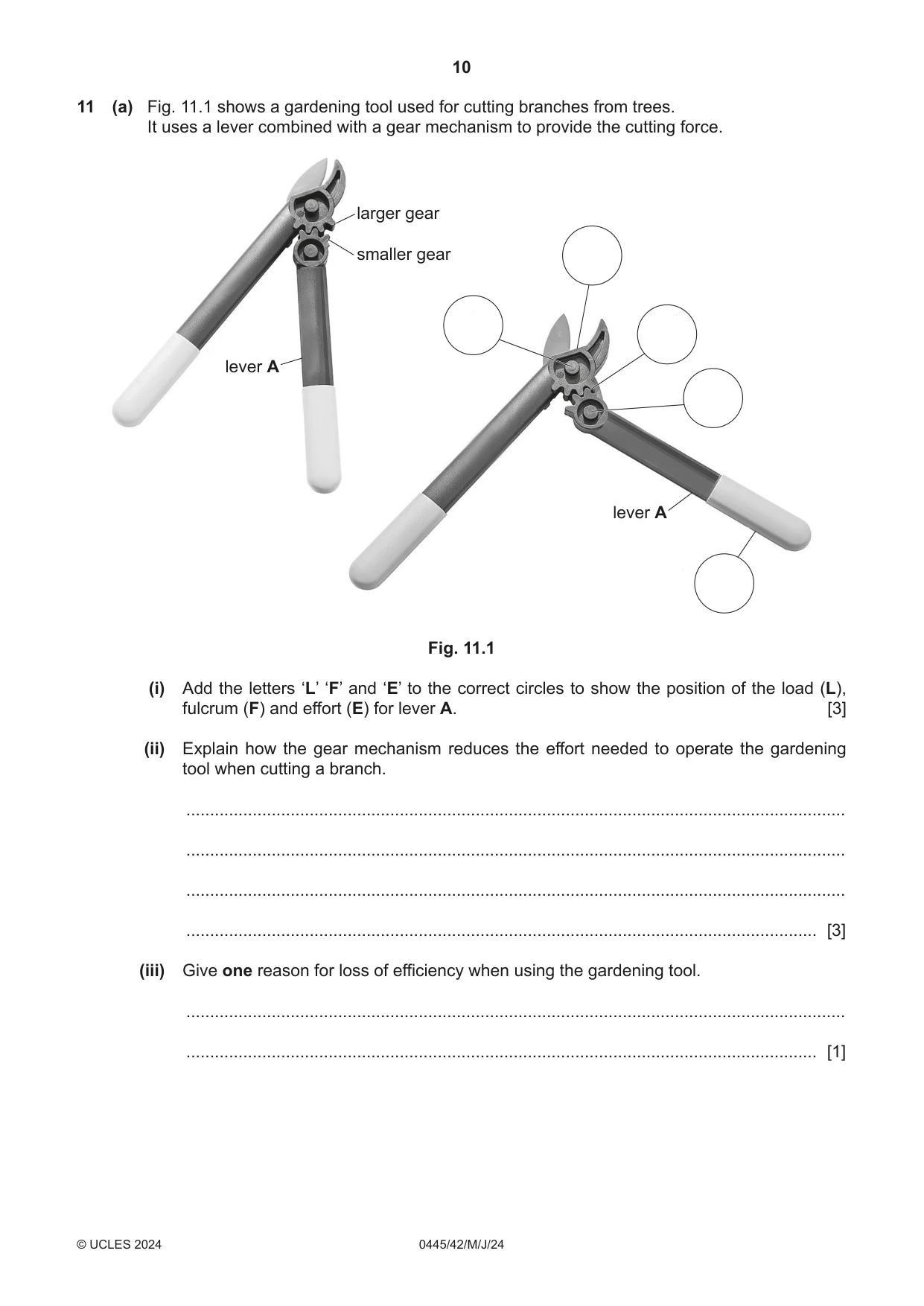
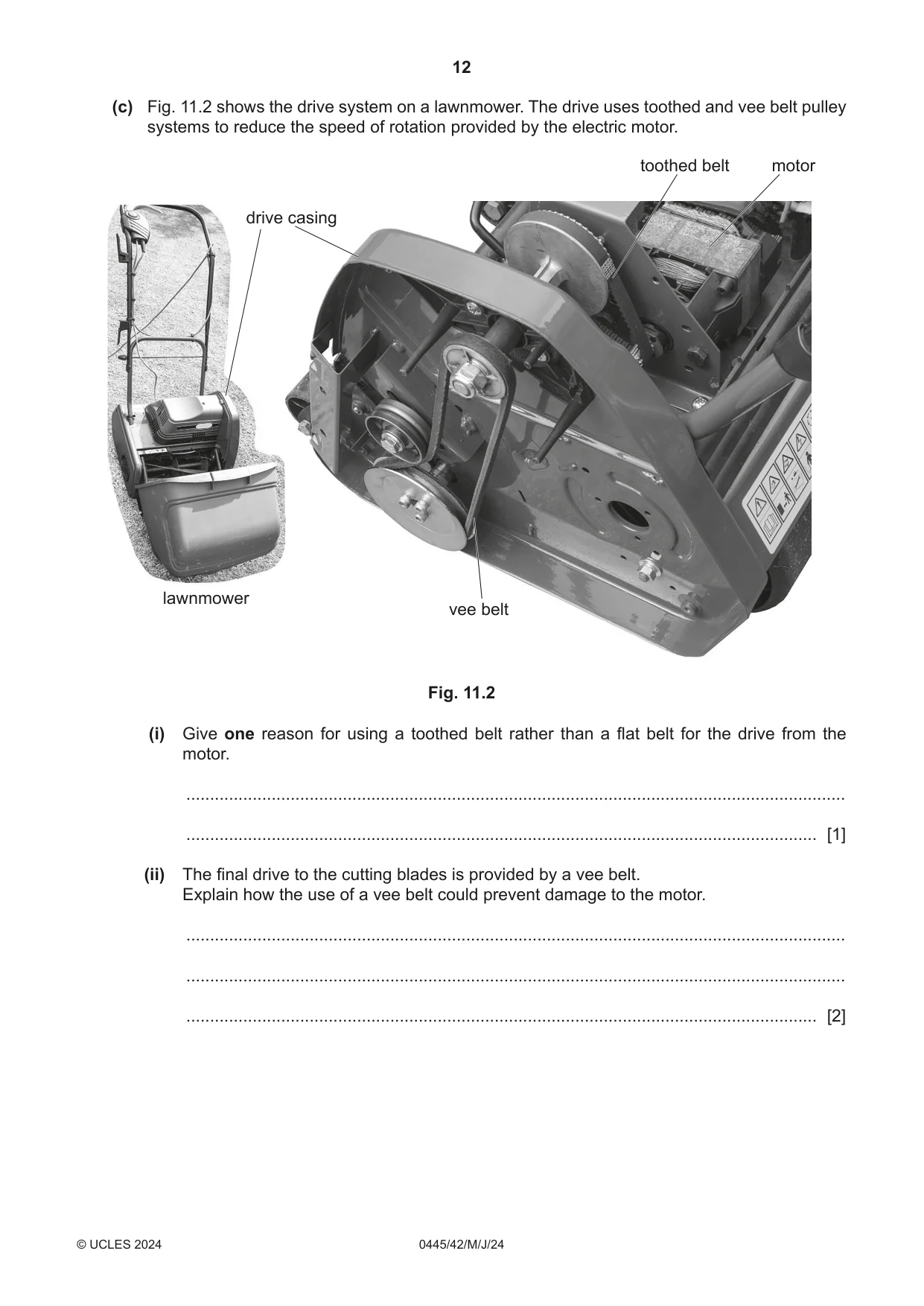
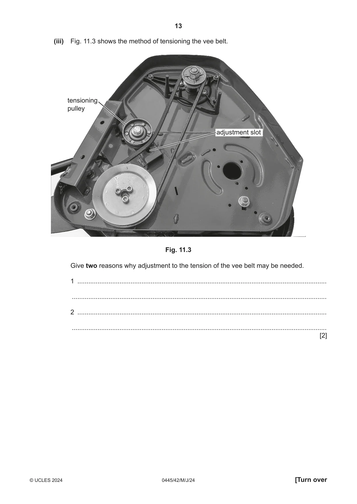
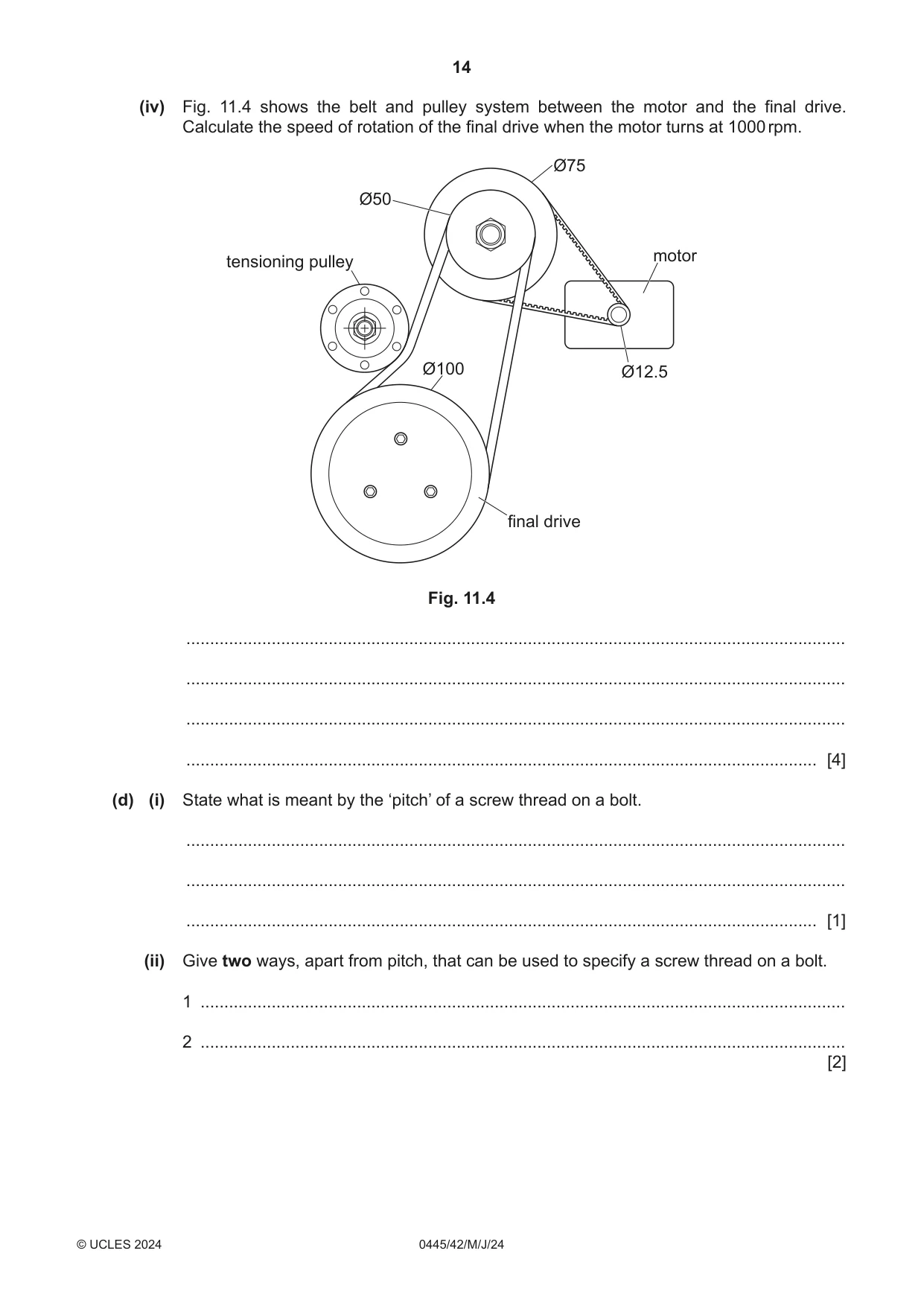
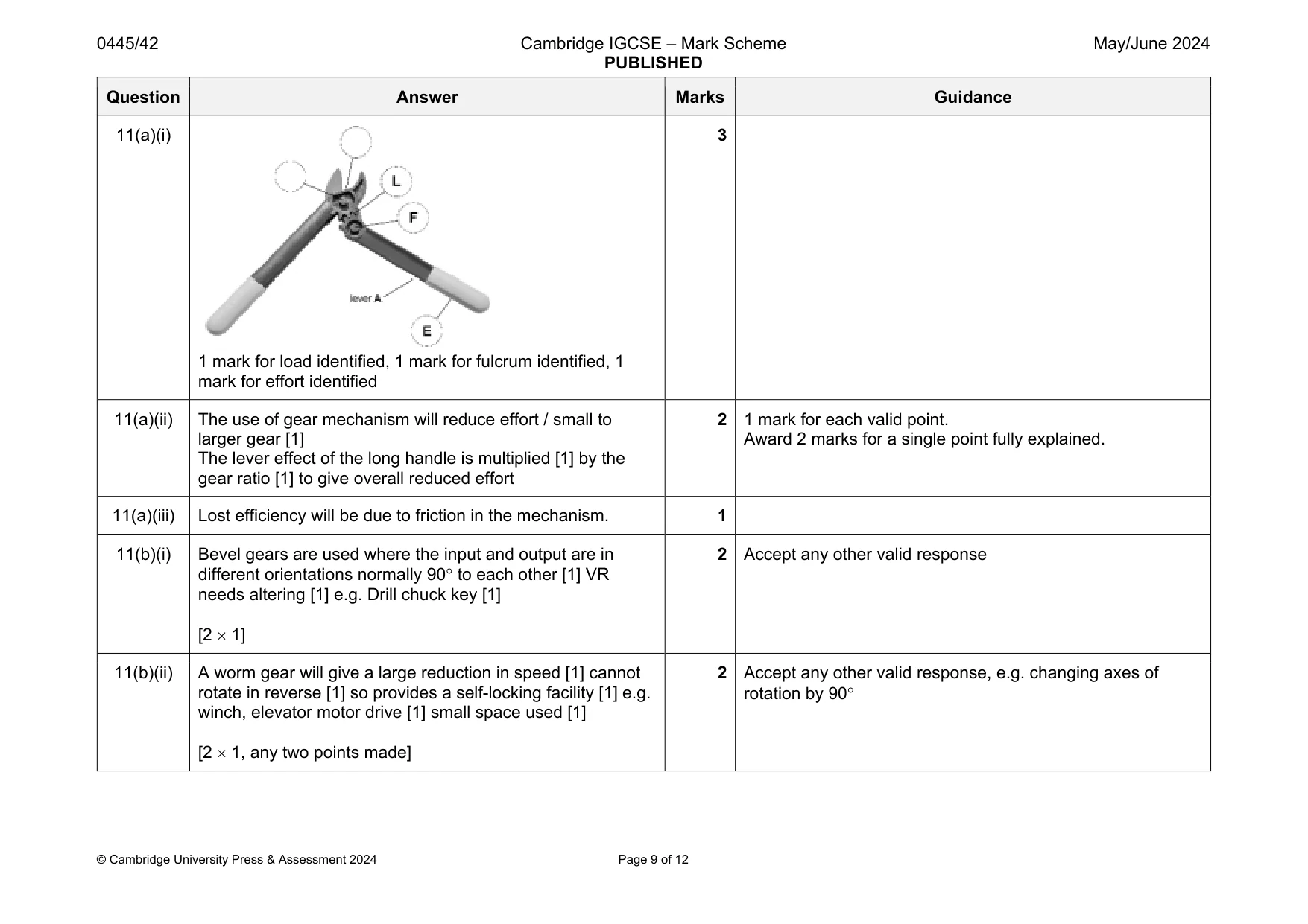
11 (a) Fig. 11.1 shows a gardening tool used for cutting branches from trees. It uses a lever combined with a gear mechanism to provide the cutting force. larger gear smaller gear lever A lever A Fig. 11.1 (i) Add the letters ‘L’ ‘F’ and ‘E’ to the correct circles to show the position of the load (L), fulcrum (F) and effort (E) for lever A. [3] (ii) Explain how the gear mechanism reduces the effort needed to operate the gardening tool when cutting a branch. ........................................................................................................................................... ........................................................................................................................................... ........................................................................................................................................... ..................................................................................................................................... [3] (iii) Give one reason for loss of efficiency when using the gardening tool. ........................................................................................................................................... ..................................................................................................................................... [1] (b) Using examples, describe why the following types of gear would be used. (i) Bevel gears ........................................................................................................................................... ........................................................................................................................................... ..................................................................................................................................... [2] (ii) Worm gear ........................................................................................................................................... ........................................................................................................................................... ..................................................................................................................................... [2] (iii) Rack and pinion gears ........................................................................................................................................... ........................................................................................................................................... ..................................................................................................................................... [2] (c) Fig. 11.2 shows the drive system on a lawnmower. The drive uses toothed and vee belt pulley systems to reduce the speed of rotation provided by the electric motor. toothed belt motor drive casing lawnmower vee belt Fig. 11.2 (i) Give one reason for using a toothed belt rather than a flat belt for the drive from the motor. ........................................................................................................................................... ..................................................................................................................................... [1] (ii) The final drive to the cutting blades is provided by a vee belt. Explain how the use of a vee belt could prevent damage to the motor. ........................................................................................................................................... ........................................................................................................................................... ..................................................................................................................................... [2] (iii) Fig. 11.3 shows the method of tensioning the vee belt. tensioning pulley adjustment slot Fig. 11.3 Give two reasons why adjustment to the tension of the vee belt may be needed. 1 ........................................................................................................................................ ........................................................................................................................................... 2 ........................................................................................................................................ ........................................................................................................................................... [2] (iv) Fig. 11.4 shows the belt and pulley system between the motor and the final drive. Calculate the speed of rotation of the final drive when the motor turns at 1000 rpm. Ø75 Ø50 motor tensioning pulley Ø100 Ø12.5 final drive Fig. 11.4 ........................................................................................................................................... ........................................................................................................................................... ........................................................................................................................................... ..................................................................................................................................... [4] (d) (i) State what is meant by the ‘pitch’ of a screw thread on a bolt. ........................................................................................................................................... ........................................................................................................................................... ..................................................................................................................................... [1] (ii) Give two ways, apart from pitch, that can be used to specify a screw thread on a bolt. 1 ........................................................................................................................................ 2 ........................................................................................................................................ [2]
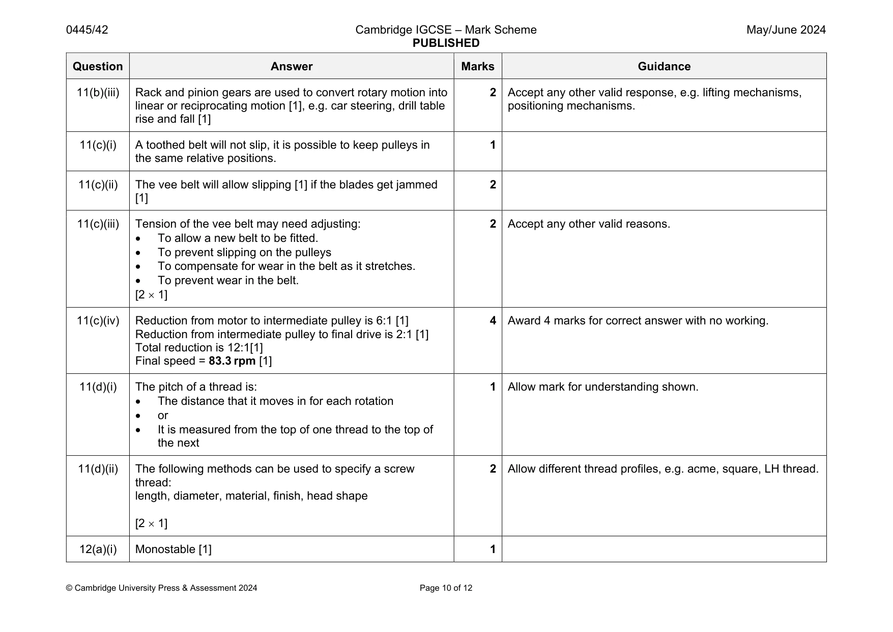
Mark scheme: 11(a)(i) 1 mark for load identified, 1 mark for fulcrum identified, 1 mark for effort identified 3 11(a)(ii) The use of gear mechanism will reduce effort / small to larger gear [1] The lever effect of the long handle is multiplied [1] by the gear ratio [1] to give overall reduced effort 2 1 mark for each valid point. Award 2 marks for a single point fully explained. 11(a)(iii) Lost efficiency will be due to friction in the mechanism. 1 11(b)(i) Bevel gears are used where the input and output are in different orientations normally 90 to each other [1] VR needs altering [1] e.g. Drill chuck key [1] [2 1] 2 Accept any other valid response 11(b)(ii) A worm gear will give a large reduction in speed [1] cannot rotate in reverse [1] so provides a self-locking facility [1] e.g. winch, elevator motor drive [1] small space used [1] [2 1, any two points made] 2 Accept any other valid response, e.g. changing axes of rotation by 90 Question Answer Marks Guidance 11(b)(iii) Rack and pinion gears are used to convert rotary motion into linear or reciprocating motion [1], e.g. car steering, drill table rise and fall [1] 2 Accept any other valid response, e.g. lifting mechanisms, positioning mechanisms. 11(c)(i) A toothed belt will not slip, it is possible to keep pulleys in the same relative positions. 1 11(c)(ii) The vee belt will allow slipping [1] if the blades get jammed [1] 2 11(c)(iii) Tension of the vee belt may need adjusting: To allow a new belt to be fitted. To prevent slipping on the pulleys To compensate for wear in the belt as it stretches. To prevent wear in the belt. [2 1] 2 Accept any other valid reasons. 11(c)(iv) Reduction from motor to intermediate pulley is 6:1 [1] Reduction from intermediate pulley to final drive is 2:1 [1] Total reduction is 12:1[1] Final speed = 83.3 rpm [1] 4 Award 4 marks for correct answer with no working. 11(d)(i) The pitch of a thread is: The distance that it moves in for each rotation or It is measured from the top of one thread to the top of the next 1 Allow mark for understanding shown. 11(d)(ii) The following methods can be used to specify a screw thread: length, diameter, material, finish, head shape [2 1] 2 Allow different thread profiles, e.g. acme, square, LH thread.
Q12 · A meter used for testing press button switches and a graph of the signal from a correctly…
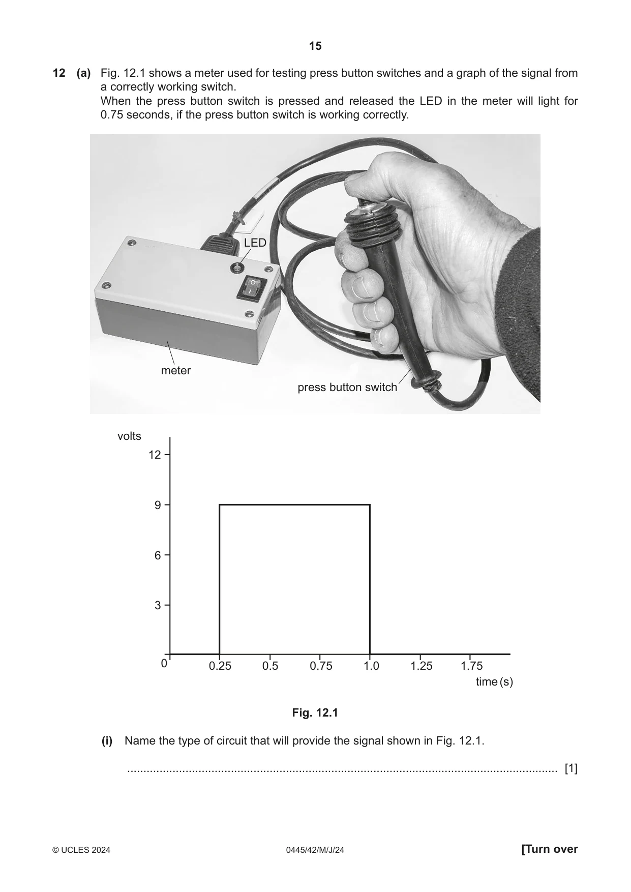
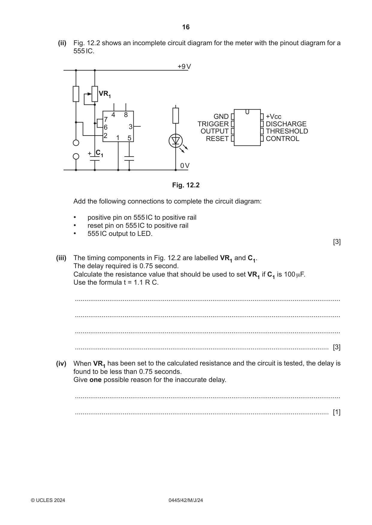
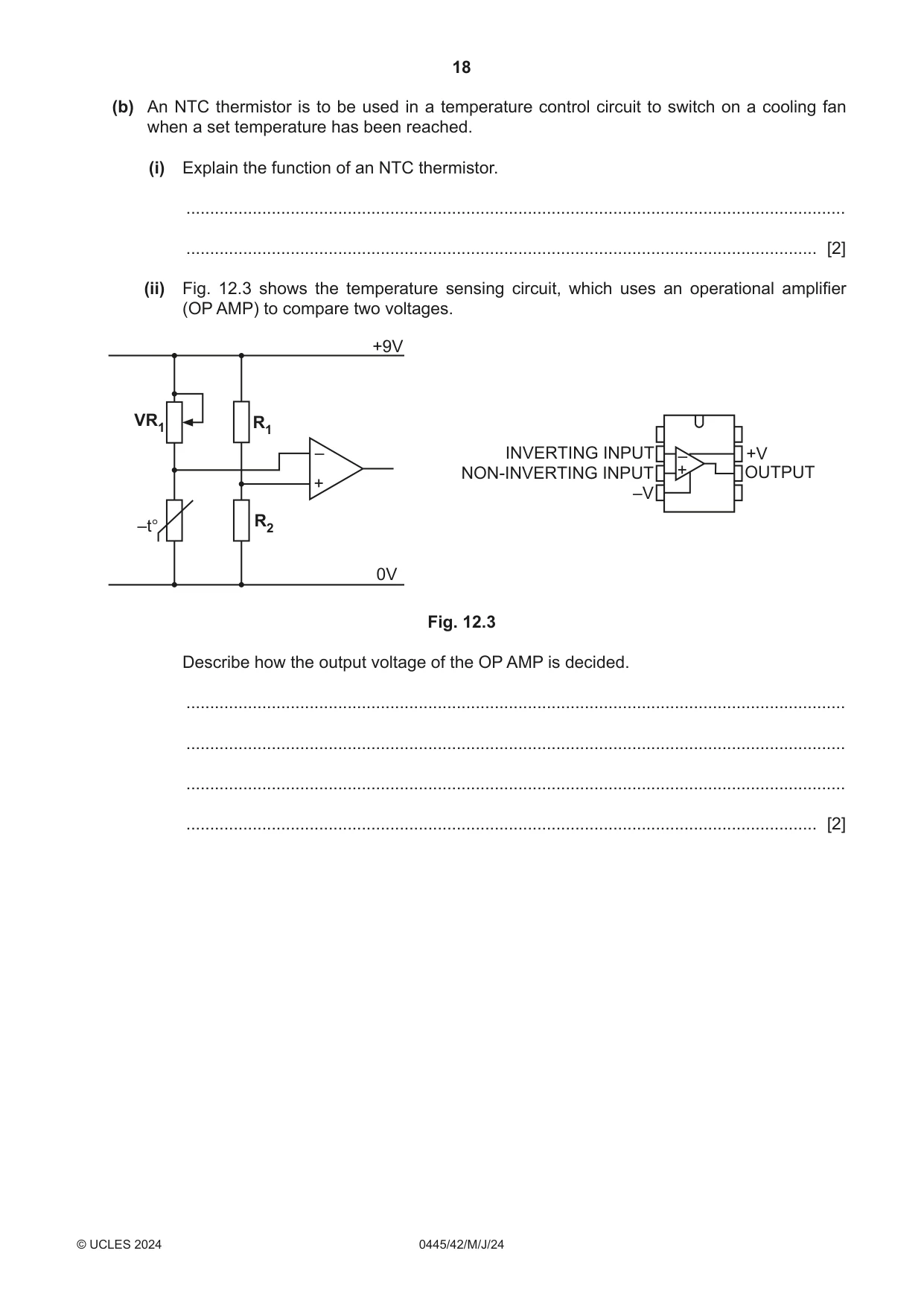
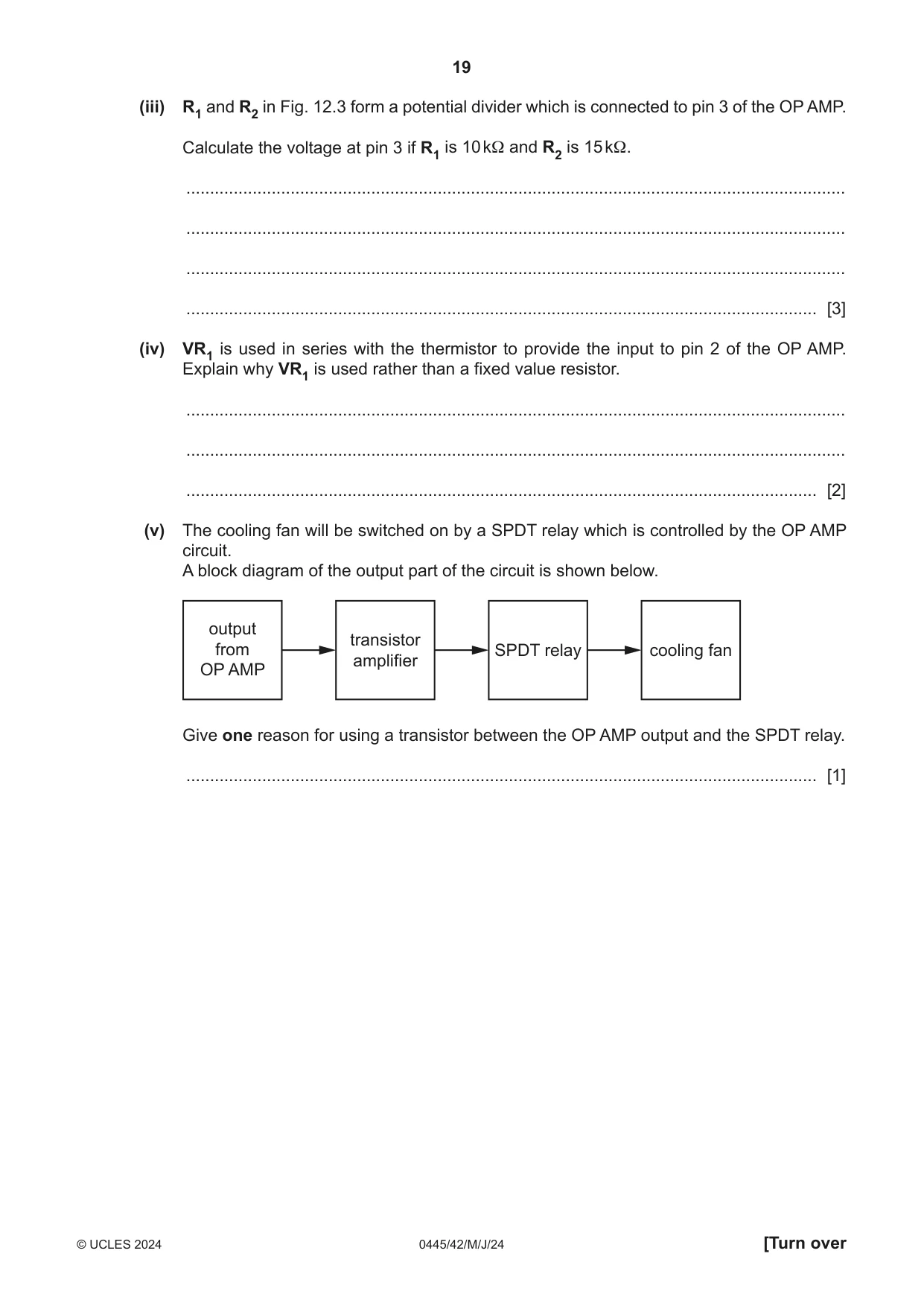
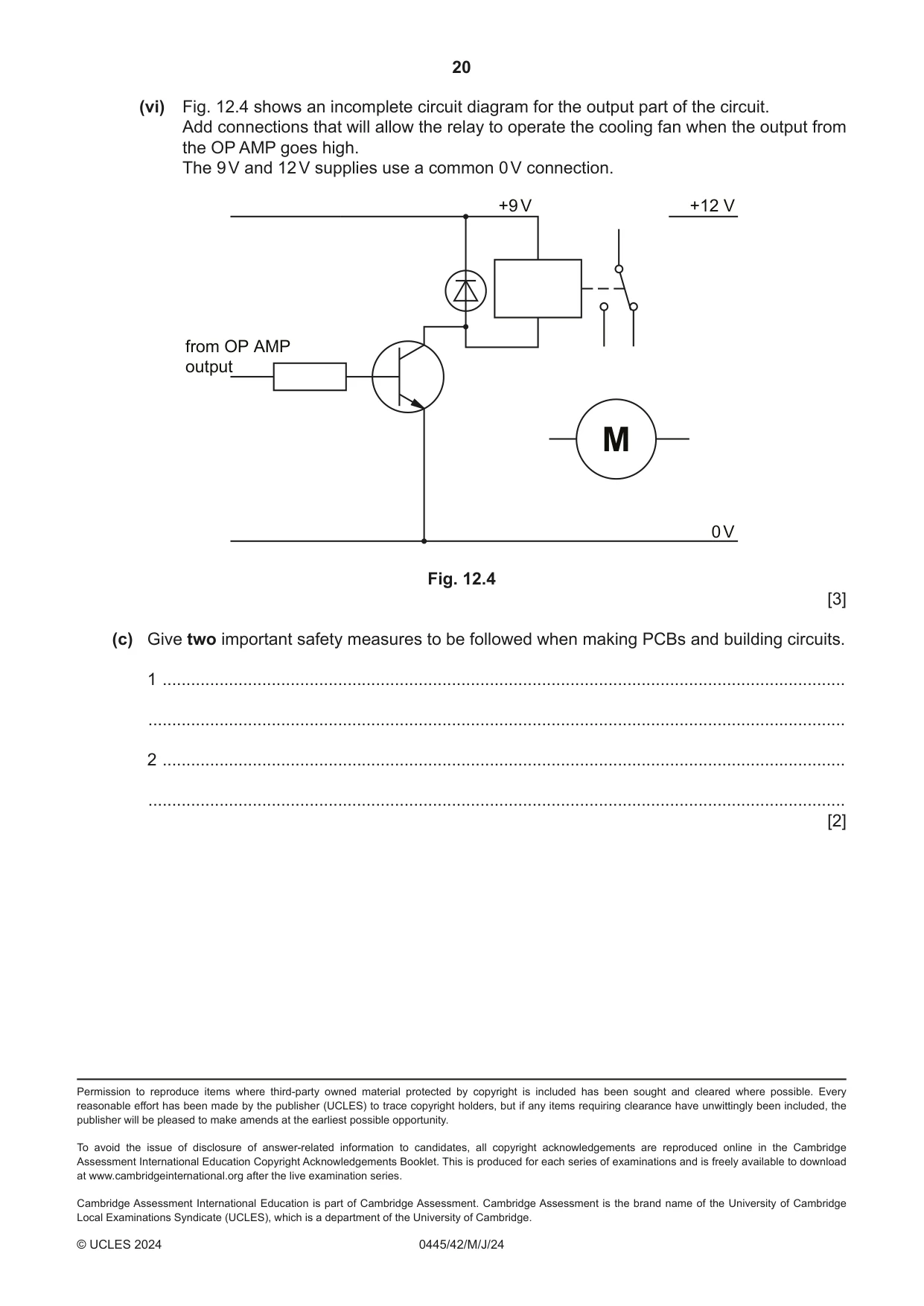
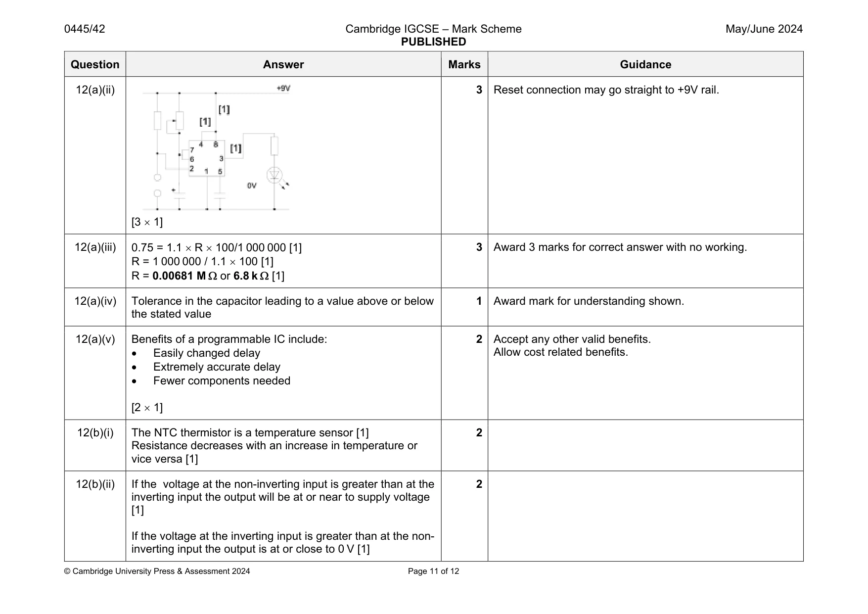
12 (a) Fig. 12.1 shows a meter used for testing press button switches and a graph of the signal from a correctly working switch. When the press button switch is pressed and released the LED in the meter will light for 0.75 seconds, if the press button switch is working correctly. LED meter press button switch volts 12 9 6 3 0 0.25 0.5 0.75 1.0 1.25 1.75 time (s) Fig. 12.1 (i) Name the type of circuit that will provide the signal shown in Fig. 12.1. ..................................................................................................................................... [1] (ii) Fig. 12.2 shows an incomplete circuit diagram for the meter with the pinout diagram for a 555 IC. +9 V VR1 4 8 GND +Vcc 7 TRIGGER DISCHARGE 6 3 OUTPUT THRESHOLD 2 1 5 RESET CONTROL + C1 0 V Fig. 12.2 Add the following connections to complete the circuit diagram: • positive pin on 555 IC to positive rail • reset pin on 555 IC to positive rail • 555 IC output to LED. [3] (iii) The timing components in Fig. 12.2 are labelled VR1 and C1. The delay required is 0.75 second. Calculate the resistance value that should be used to set VR1 if C1 is 100 µF. Use the formula t = 1.1 R C. ........................................................................................................................................... ........................................................................................................................................... ........................................................................................................................................... ..................................................................................................................................... [3] (iv) When VR1 has been set to the calculated resistance and the circuit is tested, the delay is found to be less than 0.75 seconds. Give one possible reason for the inaccurate delay. ........................................................................................................................................... ..................................................................................................................................... [1] (v) A programmable IC could have been used instead of the 555 IC. Give two benefits of using a programmable IC for the circuit. 1 ........................................................................................................................................ ........................................................................................................................................... 2 ........................................................................................................................................ ........................................................................................................................................... [2]
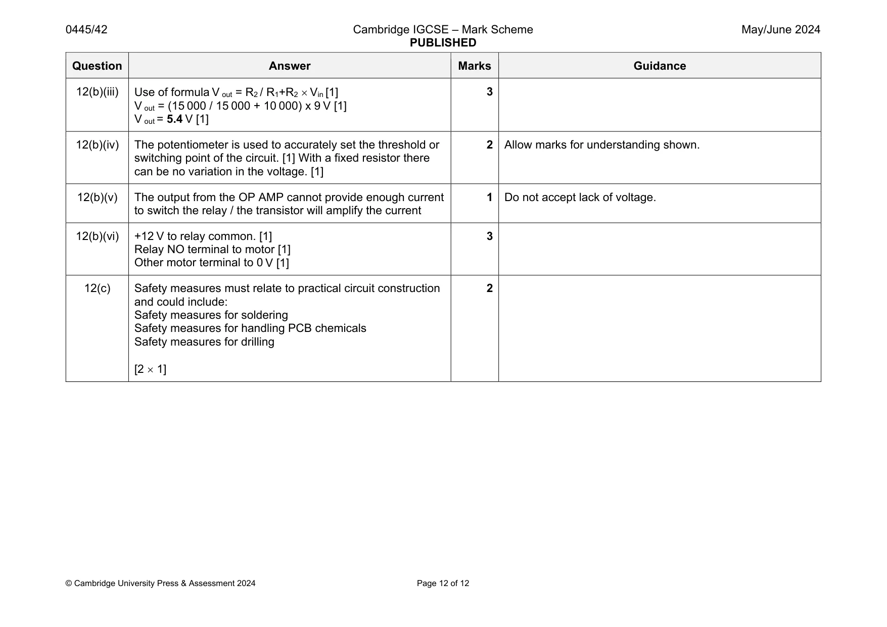
Mark scheme: 12(a)(i) Monostable [1] 1 Question Answer Marks Guidance 12(a)(ii) [3 1] 3 Reset connection may go straight to +9V rail. 12(a)(iii) 0.75 = 1.1 R 100/1 000 000 [1] R = 1 000 000 / 1.1 100 [1] R = 0.00681 M or 6.8 k [1] 3 Award 3 marks for correct answer with no working. 12(a)(iv) Tolerance in the capacitor leading to a value above or below the stated value 1 Award mark for understanding shown. 12(a)(v) Benefits of a programmable IC include: Easily changed delay Extremely accurate delay Fewer components needed [2 1] 2 Accept any other valid benefits. Allow cost related benefits. 12(b)(i) The NTC thermistor is a temperature sensor [1] Resistance decreases with an increase in temperature or vice versa [1] 2 12(b)(ii) If the voltage at the non-inverting input is greater than at the inverting input the output will be at or near to supply voltage [1] If the voltage at the inverting input is greater than at the non- inverting input the output is at or close to 0 V [1] 2 Question Answer Marks Guidance 12(b)(iii) Use of formula V out = R2 / R1+R2 Vin [1] V out = (15 000 / 15 000 + 10 000) x 9 V [1] V out = 5.4 V [1] 3 12(b)(iv) The potentiometer is used to accurately set the threshold or switching point of the circuit. [1] With a fixed resistor there can be no variation in the voltage. [1] 2 Allow marks for understanding shown. 12(b)(v) The output from the OP AMP cannot provide enough current to switch the relay / the transistor will amplify the current 1 Do not accept lack of voltage. 12(b)(vi) +12 V to relay common. [1] Relay NO terminal to motor [1] Other motor terminal to 0 V [1] 3 12(c) Safety measures must relate to practical circuit construction and could include: Safety measures for soldering Safety measures for handling PCB chemicals Safety measures for drilling [2 1] 2
What was in this paper
The subtopics covered by these 12 questions, and how many questions each got. Open one in a new tab to see every Cambridge question on it.
What you needed in this session
Cambridge’s own grade thresholds for 2024 May/June, Paper 4 · Variant 2. A higher threshold means an easier paper — the bar moves with how the cohort did.