Cambridge IGCSE Design and Technology 0445 — 2021 May/June Paper 4 · Variant 3
0445/43/M/J/21 · 12 questions · 50 marks · ≈56 min
The question paper and its mark scheme, free to read here and free to download. This is Cambridge’s own paper, exactly as it was sat.
Question paper20 pages
Mark scheme13 pages
Answers below. Sit the paper first if you are practising.
Questions as text
Q1 · A list of materials that can be used in a structure is given below
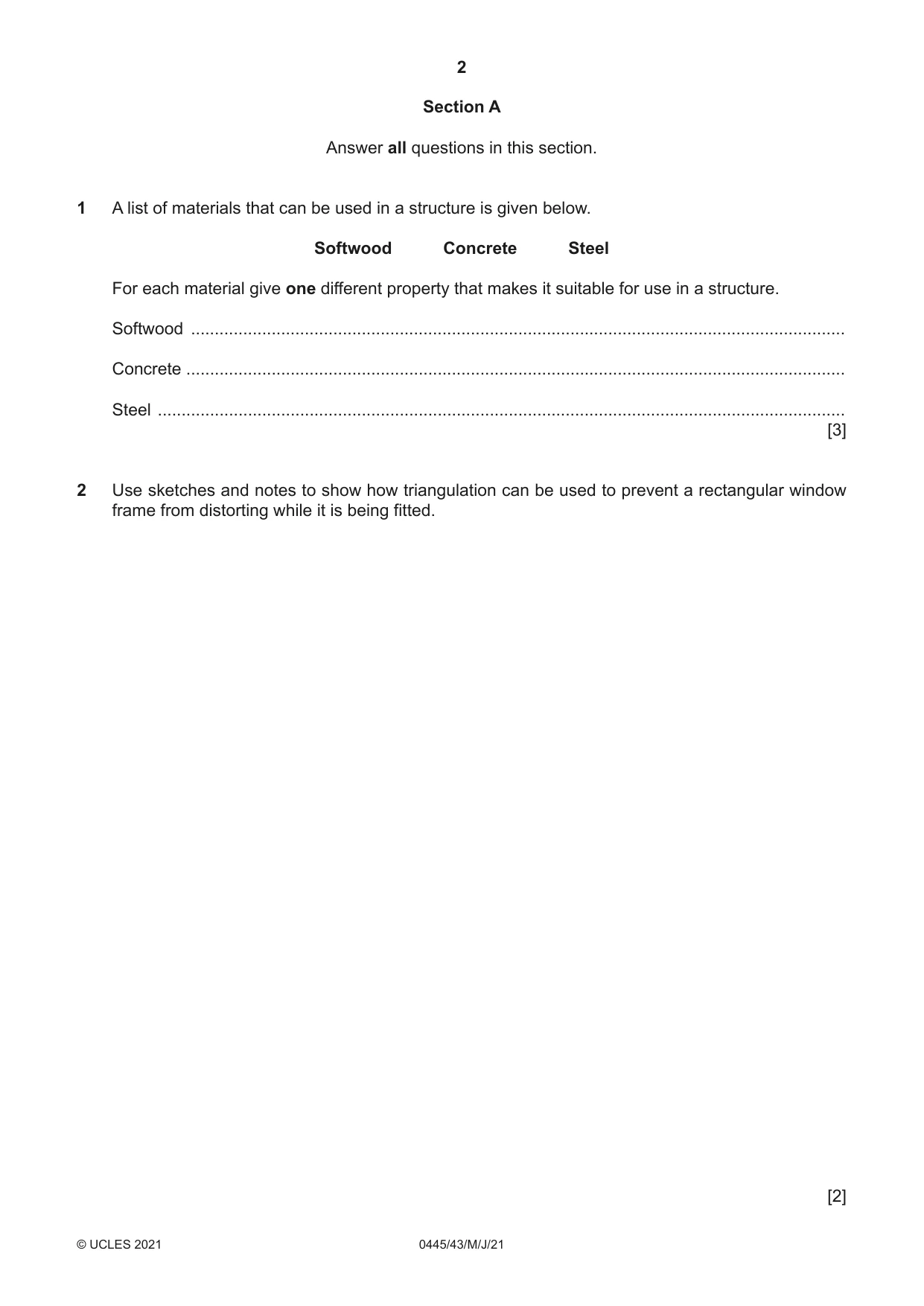
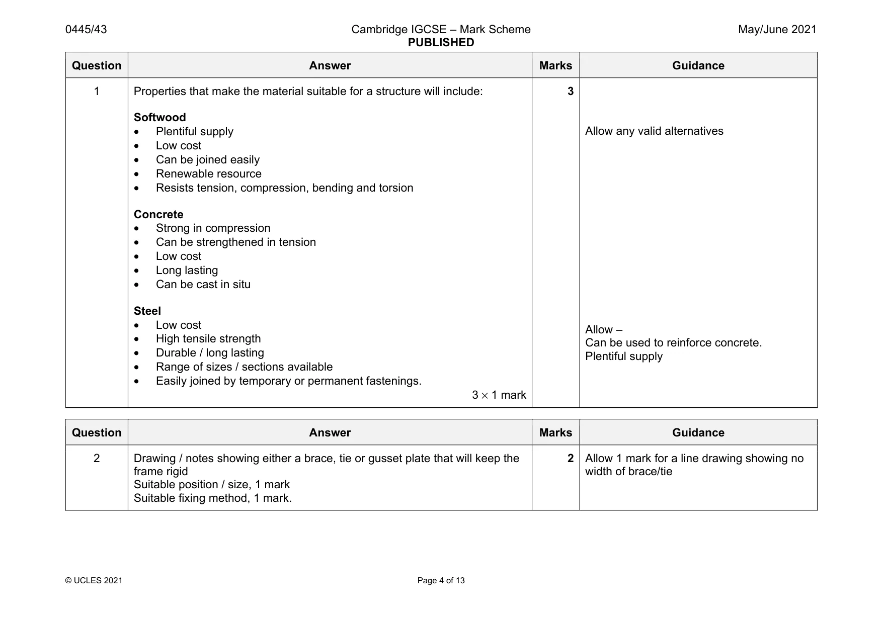
1 A list of materials that can be used in a structure is given below. Softwood Concrete Steel For each material give one different property that makes it suitable for use in a structure. Softwood .......................................................................................................................................... Concrete ........................................................................................................................................... Steel ................................................................................................................................................. [3]
Mark scheme: 1 Properties that make the material suitable for a structure will include: Softwood • Plentiful supply • Low cost • Can be joined easily • Renewable resource • Resists tension, compression, bending and torsion Concrete • Strong in compression • Can be strengthened in tension • Low cost • Long lasting • Can be cast in situ Steel • Low cost • High tensile strength • Durable / long lasting • Range of sizes / sections available • Easily joined by temporary or permanent fastenings. 3 × 1 mark 3 Allow any valid alternatives Allow – Can be used to reinforce concrete. Plentiful supply
Q2 · Use sketches and notes to show how triangulation can be used to prevent a rectangular…
2 Use sketches and notes to show how triangulation can be used to prevent a rectangular window frame from distorting while it is being fitted. [2]
Mark scheme: 2 Drawing / notes showing either a brace, tie or gusset plate that will keep the frame rigid Suitable position / size, 1 mark Suitable fixing method, 1 mark. 2 Allow 1 mark for a line drawing showing no width of brace/tie
Q3 · Salad tongs, which are an example of a third order lever
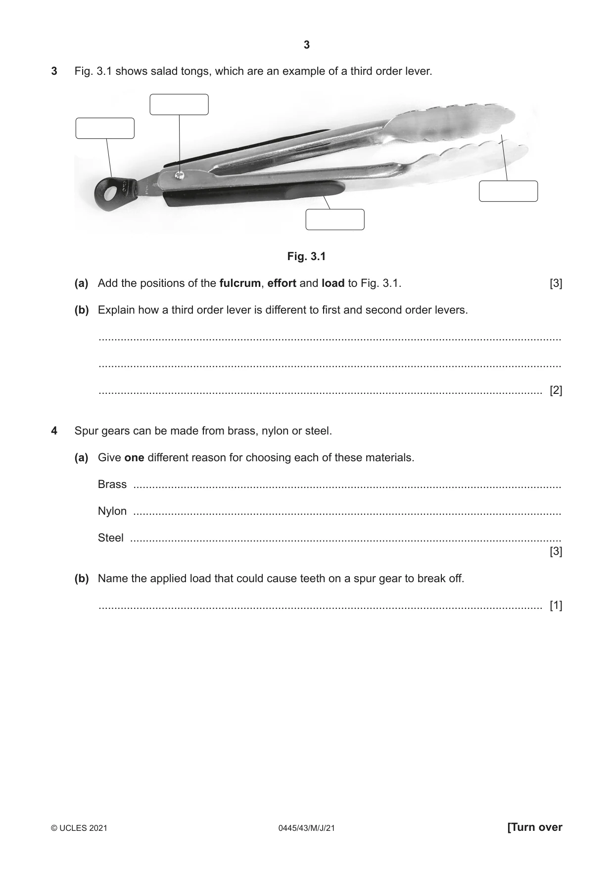
3 Fig. 3.1 shows salad tongs, which are an example of a third order lever. Fig. 3.1 (a) Add the positions of the fulcrum, effort and load to Fig. 3.1. [3] (b) Explain how a third order lever is different to first and second order levers. ................................................................................................................................................... ................................................................................................................................................... ............................................................................................................................................. [2]
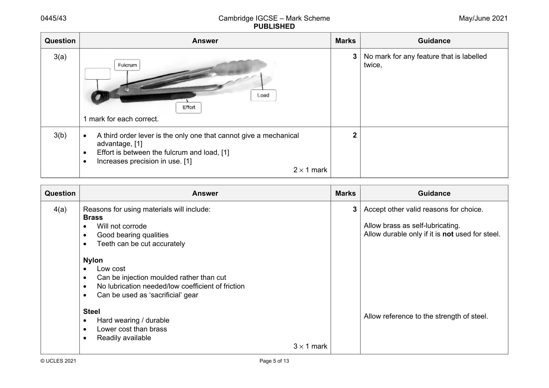
Mark scheme: 3(a) 1 mark for each correct. twice, 3(b) • A third order lever is the only one that cannot give a mechanical advantage, [1] • Effort is between the fulcrum and load, [1] • Increases precision in use. [1] 2 × 1 mark 2
Q4 · Spur gears can be made from brass, nylon or steel
4 Spur gears can be made from brass, nylon or steel. (a) Give one different reason for choosing each of these materials. Brass ........................................................................................................................................ Nylon ........................................................................................................................................ Steel ......................................................................................................................................... [3] (b) Name the applied load that could cause teeth on a spur gear to break off. ............................................................................................................................................. [1]
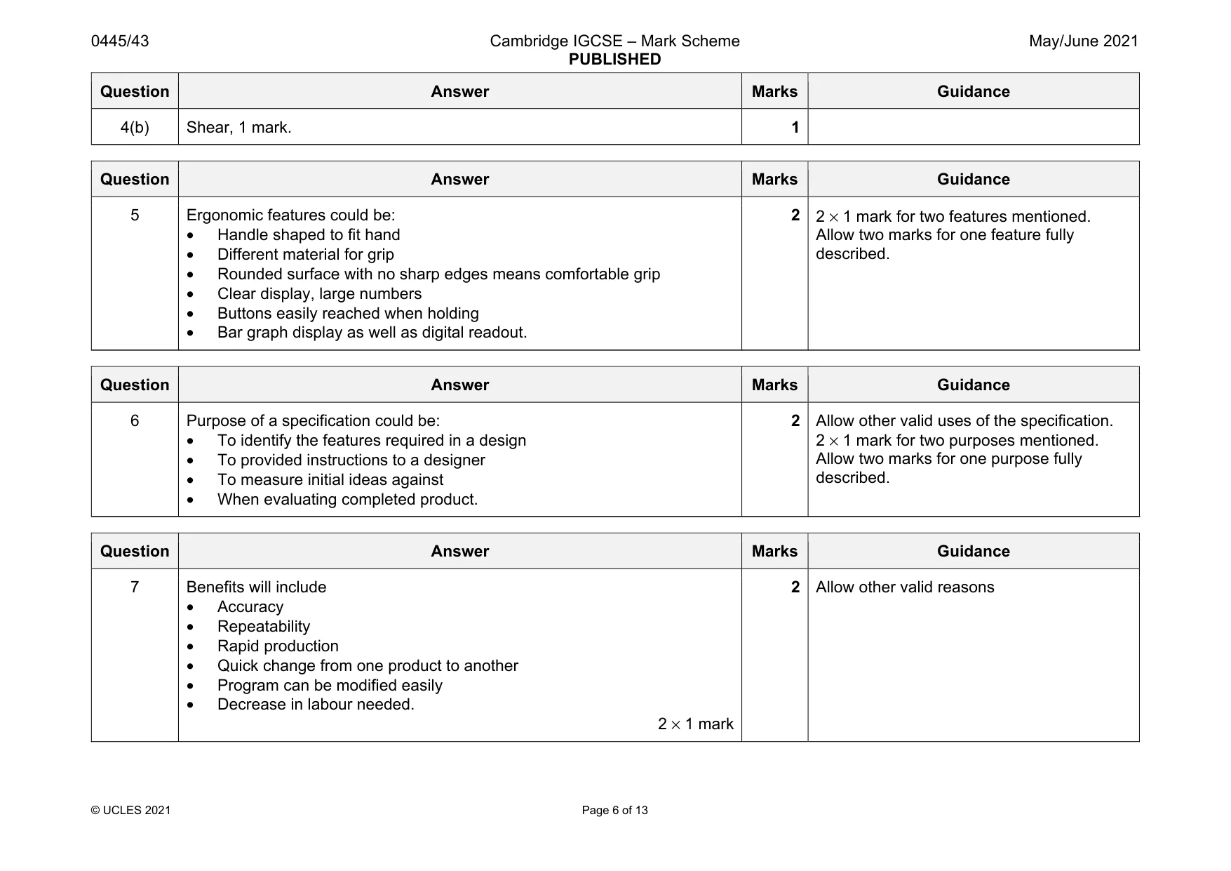
Mark scheme: 4(a) Reasons for using materials will include: Brass • Will not corrode • Good bearing qualities • Teeth can be cut accurately Nylon • Low cost • Can be injection moulded rather than cut • No lubrication needed/low coefficient of friction • Can be used as ‘sacrificial’ gear Steel • Hard wearing / durable • Lower cost than brass • Readily available 3 × 1 mark Allow brass as self-lubricating. Allow durable only if it is not used for steel. Allow reference to the strength of steel. Question Answer Marks Guidance 4(b) Shear, 1 mark. 1
Q5 · A hand held moisture meter for testing moisture content in wood
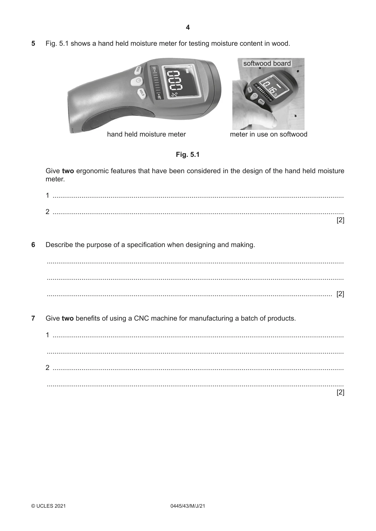
5 Fig. 5.1 shows a hand held moisture meter for testing moisture content in wood. softwood board hand held moisture meter meter in use on softwood Fig. 5.1 Give two ergonomic features that have been considered in the design of the hand held moisture meter. 1 ....................................................................................................................................................... 2 ....................................................................................................................................................... [2]
Mark scheme: 5 Ergonomic features could be: • Handle shaped to fit hand • Different material for grip • Rounded surface with no sharp edges means comfortable grip • Clear display, large numbers • Buttons easily reached when holding • Bar graph display as well as digital readout. 2 2 × 1 mark for two features mentioned. Allow two marks for one feature fully described.
Q6 · Describe the purpose of a specification when designing and making
6 Describe the purpose of a specification when designing and making. .......................................................................................................................................................... .......................................................................................................................................................... .................................................................................................................................................... [2]
Mark scheme: 6 Purpose of a specification could be: • To identify the features required in a design • To provided instructions to a designer • To measure initial ideas against • When evaluating completed product. 2 Allow other valid uses of the specification. 2 × 1 mark for two purposes mentioned. Allow two marks for one purpose fully described.
Q7 · Give two benefits of using a CNC machine for manufacturing a batch of products
7 Give two benefits of using a CNC machine for manufacturing a batch of products. 1 ....................................................................................................................................................... .......................................................................................................................................................... 2 ....................................................................................................................................................... .......................................................................................................................................................... [2]
Mark scheme: 7 Benefits will include • Accuracy • Repeatability • Rapid production • Quick change from one product to another • Program can be modified easily • Decrease in labour needed. 2 × 1 mark 2 Allow other valid reasons
Q8 · A simple electronic circuit
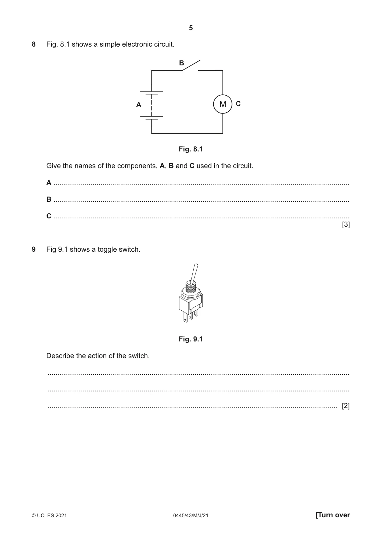
8 Fig. 8.1 shows a simple electronic circuit. B A M C Fig. 8.1 Give the names of the components, A, B and C used in the circuit. A ....................................................................................................................................................... B ....................................................................................................................................................... C ....................................................................................................................................................... [3]
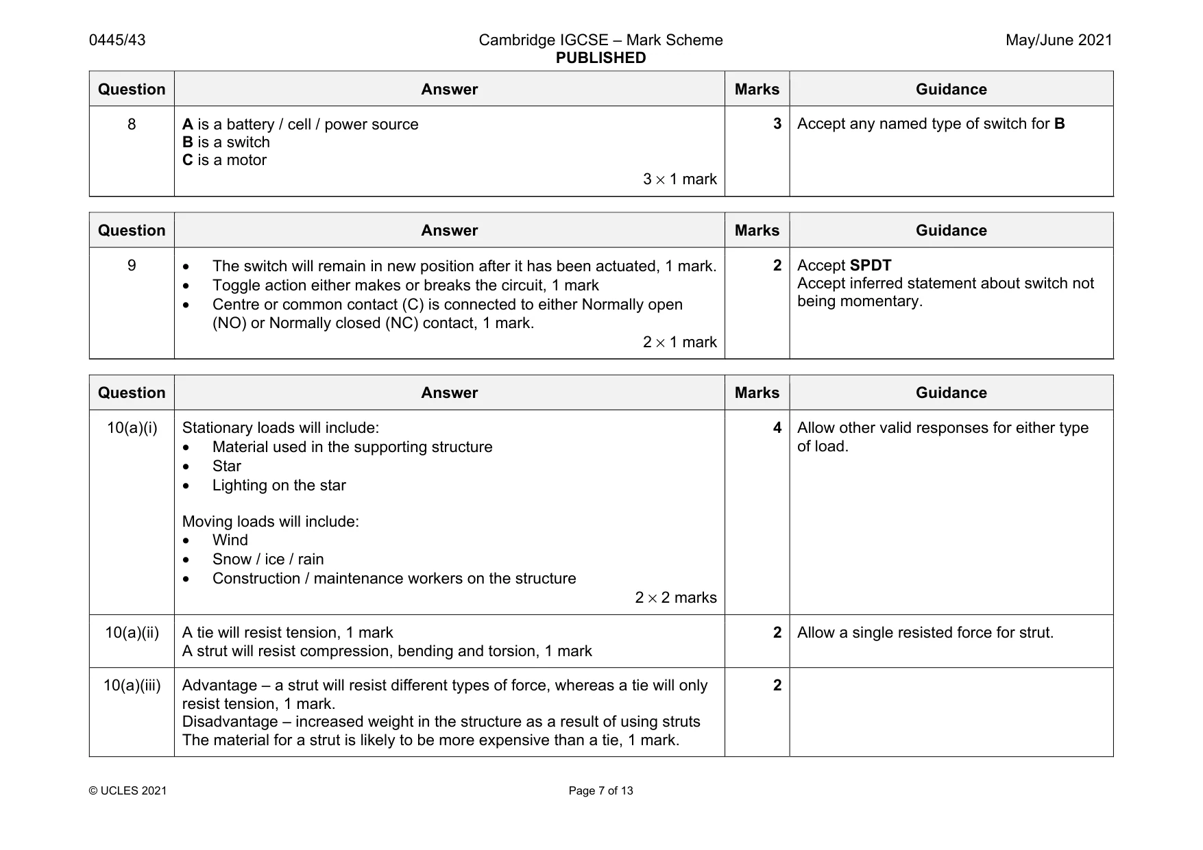
Mark scheme: 8 A is a battery / cell / power source B is a switch C is a motor 3 × 1 mark
Question 9
9 Fig 9.1 shows a toggle switch. Fig. 9.1 Describe the action of the switch. .......................................................................................................................................................... .......................................................................................................................................................... .................................................................................................................................................... [2]
Mark scheme: 9 • The switch will remain in new position after it has been actuated, 1 mark. • Toggle action either makes or breaks the circuit, 1 mark • Centre or common contact (C) is connected to either Normally open (NO) or Normally closed (NC) contact, 1 mark. 2 × 1 mark 2 Accept SPDT Accept inferred statement about switch not being momentary.
Q10 · A 27 m high structure used to support an illuminated star
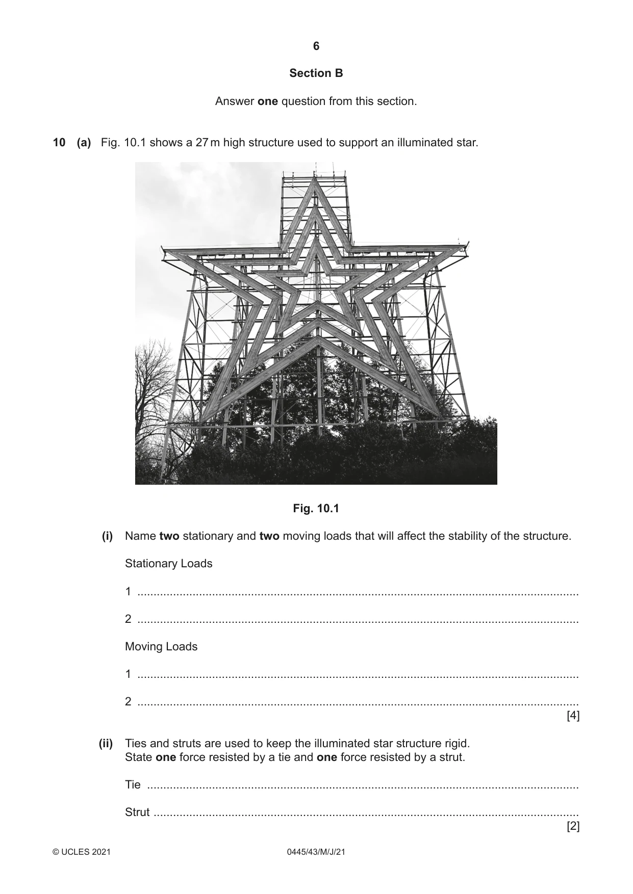
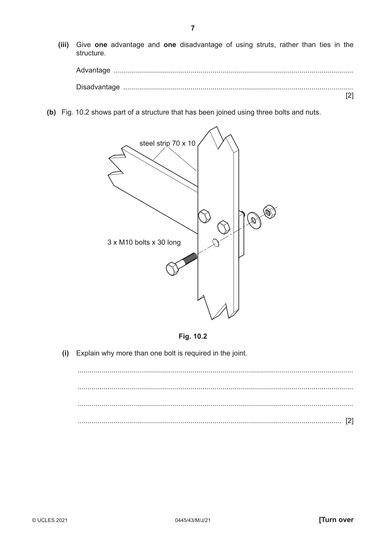
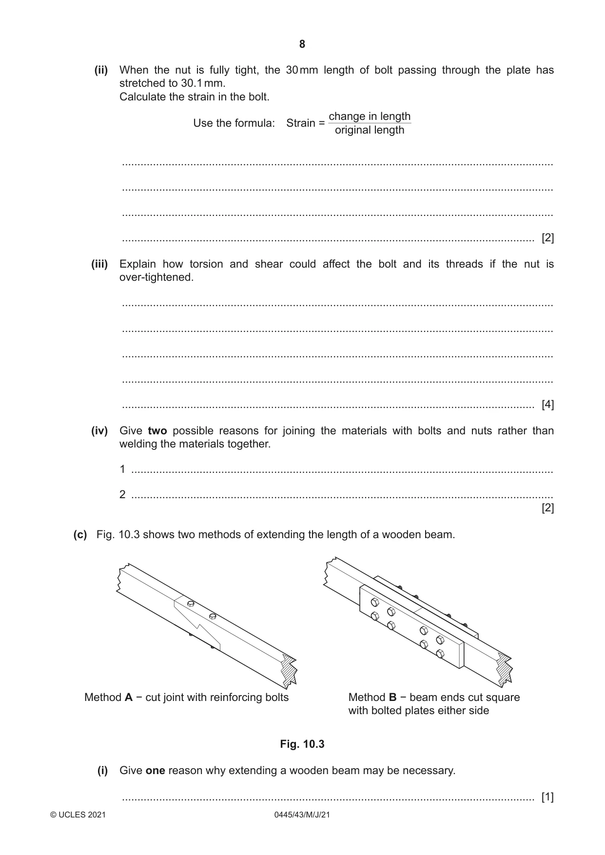
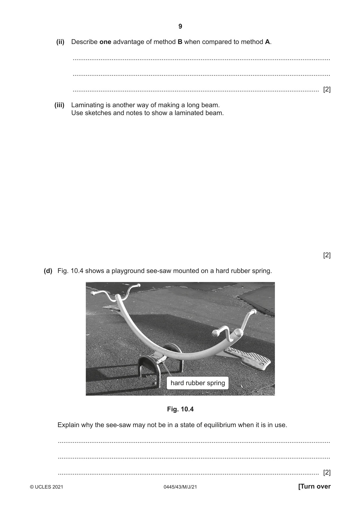
10 (a) Fig. 10.1 shows a 27 m high structure used to support an illuminated star. Fig. 10.1 (i) Name two stationary and two moving loads that will affect the stability of the structure. Stationary Loads 1 ........................................................................................................................................ 2 ........................................................................................................................................ Moving Loads 1 ........................................................................................................................................ 2 ........................................................................................................................................ [4] (ii) Ties and struts are used to keep the illuminated star structure rigid. State one force resisted by a tie and one force resisted by a strut. Tie ..................................................................................................................................... Strut ................................................................................................................................... [2] (iii) Give one advantage and one disadvantage of using struts, rather than ties in the structure. Advantage ......................................................................................................................... Disadvantage .................................................................................................................... [2] (b) Fig. 10.2 shows part of a structure that has been joined using three bolts and nuts. steel strip 70 x 10 3 x M10 bolts x 30 long Fig. 10.2 (i) Explain why more than one bolt is required in the joint. ........................................................................................................................................... ........................................................................................................................................... ........................................................................................................................................... ..................................................................................................................................... [2] (ii) When the nut is fully tight, the 30 mm length of bolt passing through the plate has stretched to 30.1 mm. Calculate the strain in the bolt. change in length Use the formula: Strain = original length ........................................................................................................................................... ........................................................................................................................................... ........................................................................................................................................... ..................................................................................................................................... [2] (iii) Explain how torsion and shear could affect the bolt and its threads if the nut is over-tightened. ........................................................................................................................................... ........................................................................................................................................... ........................................................................................................................................... ........................................................................................................................................... ..................................................................................................................................... [4] (iv) Give two possible reasons for joining the materials with bolts and nuts rather than welding the materials together. 1 ........................................................................................................................................ 2 ........................................................................................................................................ [2] (c) Fig. 10.3 shows two methods of extending the length of a wooden beam. Method A − cut joint with reinforcing bolts Method B − beam ends cut square with bolted plates either side Fig. 10.3 (i) Give one reason why extending a wooden beam may be necessary. ..................................................................................................................................... [1] (ii) Describe one advantage of method B when compared to method A. ........................................................................................................................................... ........................................................................................................................................... ..................................................................................................................................... [2] (iii) Laminating is another way of making a long beam. Use sketches and notes to show a laminated beam. [2] (d) Fig. 10.4 shows a playground see-saw mounted on a hard rubber spring. hard rubber spring Fig. 10.4 Explain why the see-saw may not be in a state of equilibrium when it is in use. ................................................................................................................................................... ................................................................................................................................................... ............................................................................................................................................. [2]
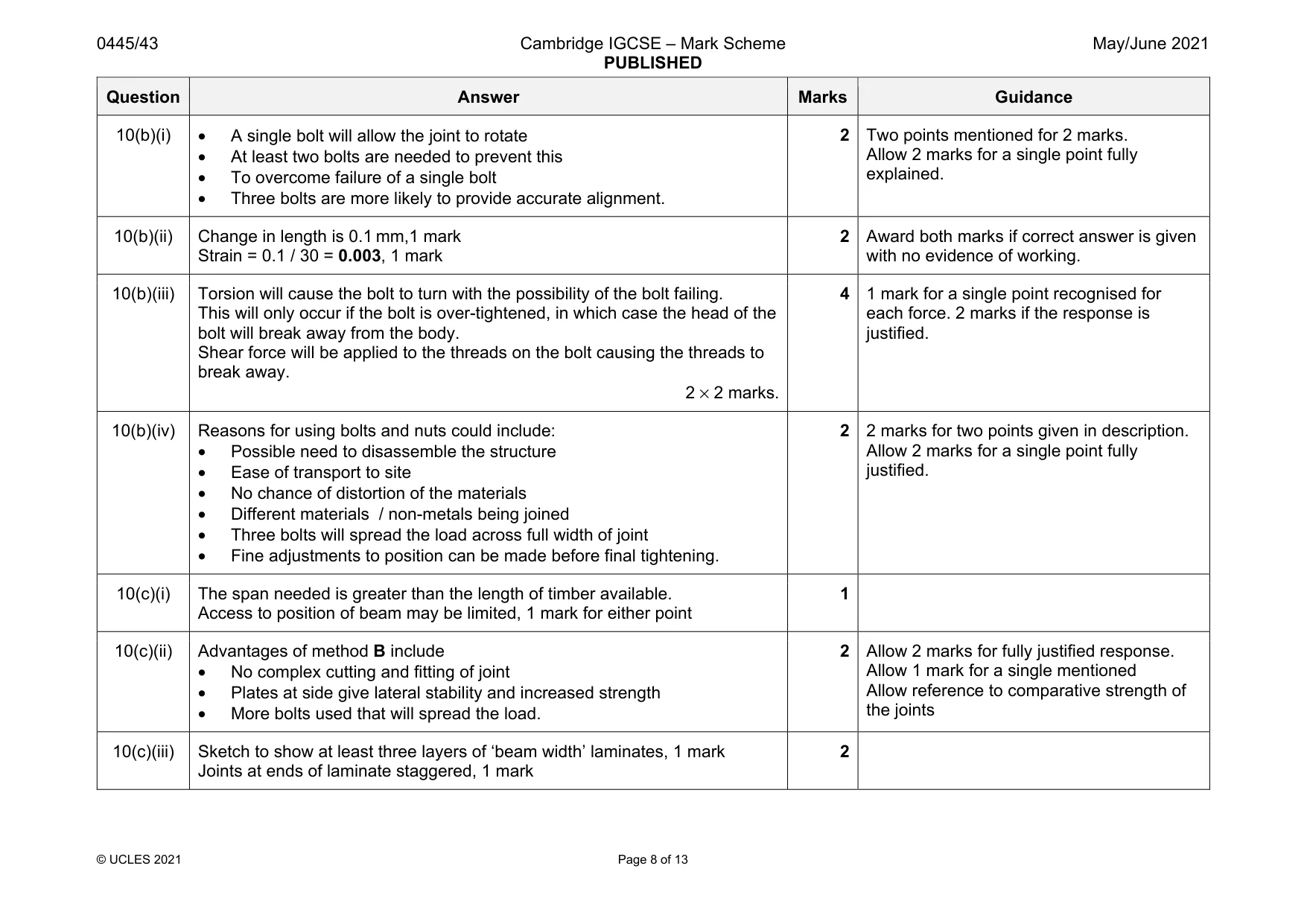
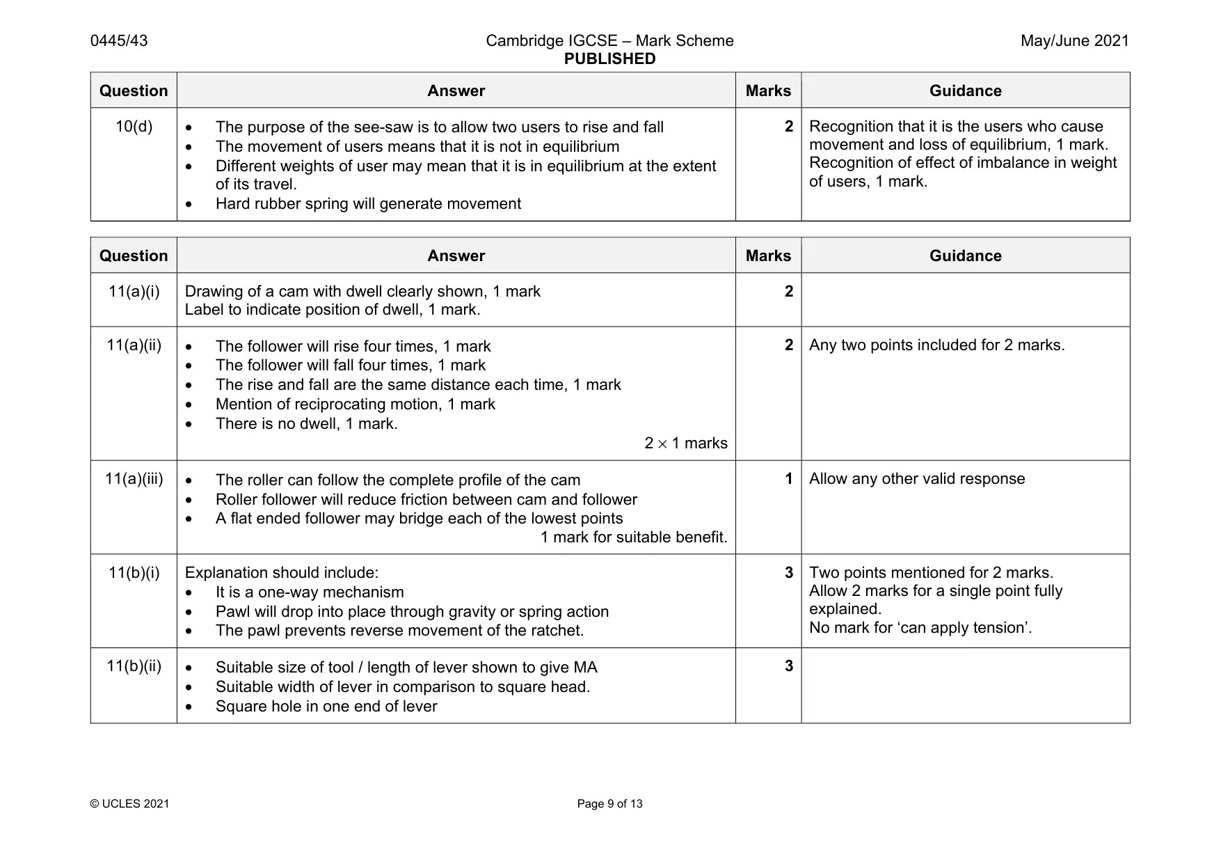
Mark scheme: 10(a)(i) Stationary loads will include: • Material used in the supporting structure • Star • Lighting on the star Moving loads will include: • Wind • Snow / ice / rain • Construction / maintenance workers on the structure 2 × 2 marks 4 Allow other valid responses for either type of load. 10(a)(ii) A tie will resist tension, 1 mark A strut will resist compression, bending and torsion, 1 mark 2 Allow a single resisted force for strut. 10(a)(iii) Advantage – a strut will resist different types of force, whereas a tie will only resist tension, 1 mark. Disadvantage – increased weight in the structure as a result of using struts The material for a strut is likely to be more expensive than a tie, 1 mark. 2 Question Answer Marks Guidance 10(b)(i) • A single bolt will allow the joint to rotate • At least two bolts are needed to prevent this • To overcome failure of a single bolt • Three bolts are more likely to provide accurate alignment. 2 Two points mentioned for 2 marks. Allow 2 marks for a single point fully explained. 10(b)(ii) Change in length is 0.1 mm,1 mark Strain = 0.1 / 30 = 0.003, 1 mark 2 Award both marks if correct answer is given with no evidence of working. 10(b)(iii) Torsion will cause the bolt to turn with the possibility of the bolt failing. This will only occur if the bolt is over-tightened, in which case the head of the bolt will break away from the body. Shear force will be applied to the threads on the bolt causing the threads to break away. 2 × 2 marks. 4 1 mark for a single point recognised for each force. 2 marks if the response is justified. 10(b)(iv) Reasons for using bolts and nuts could include: • Possible need to disassemble the structure • Ease of transport to site • No chance of distortion of the materials • Different materials / non-metals being joined • Three bolts will spread the load across full width of joint • Fine adjustments to position can be made before final tightening. 2 2 marks for two points given in description. Allow 2 marks for a single point fully justified. 10(c)(i) The span needed is greater than the length of timber available. Access to position of beam may be limited, 1 mark for either point 1 10(c)(ii) Advantages of method B include • No complex cutting and fitting of joint • Plates at side give lateral stability and increased strength • More bolts used that will spread the load. 2 Allow 2 marks for fully justified response. Allow 1 mark for a single mentioned Allow reference to comparative strength of the joints 10(c)(iii) Sketch to show at least three layers of ‘beam width’ laminates, 1 mark Joints at ends of laminate staggered, 1 mark 2 Question Answer Marks Guidance 10(d) • The purpose of the see-saw is to allow two users to rise and fall • The movement of users means that it is not in equilibrium • Different weights of user may mean that it is in equilibrium at the extent of its travel. • Hard rubber spring will generate movement 2 Recognition that it is the users who cause movement and loss of equilibrium, 1 mark. Recognition of effect of imbalance in weight of users, 1 mark.
Q11 · Use sketches and notes to show the meaning of the term ‘dwell’ in a cam
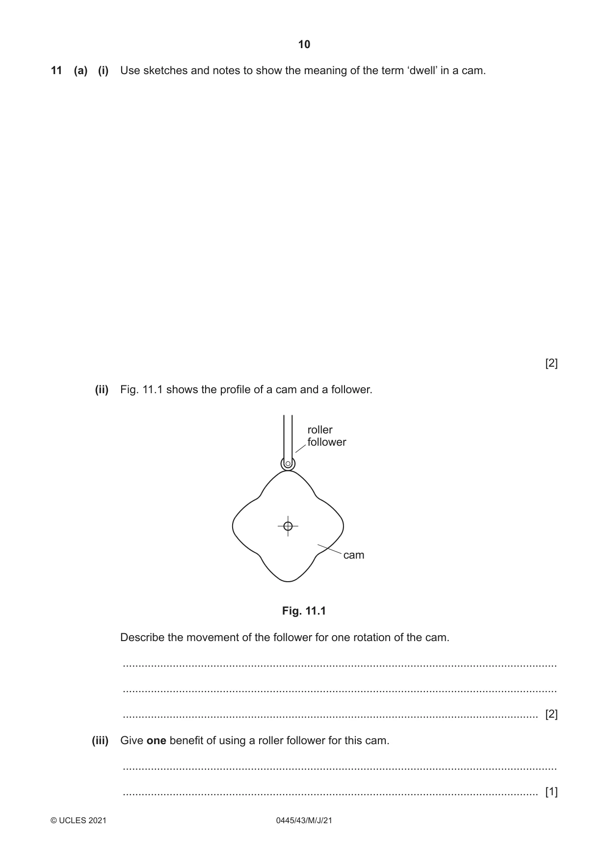
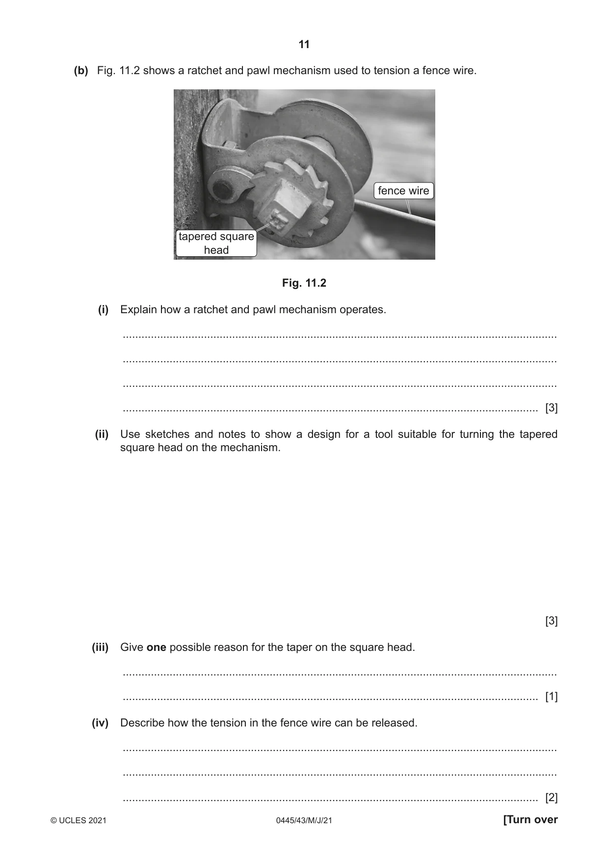
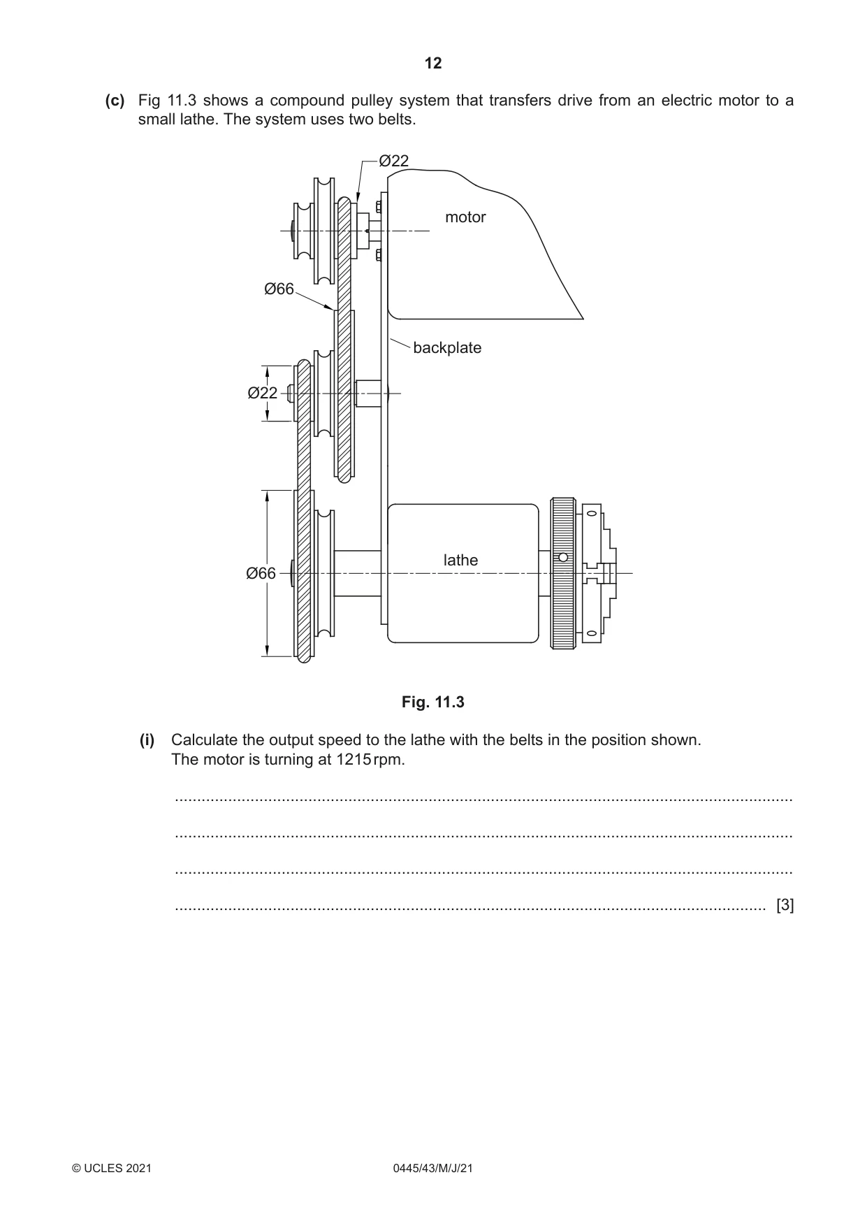
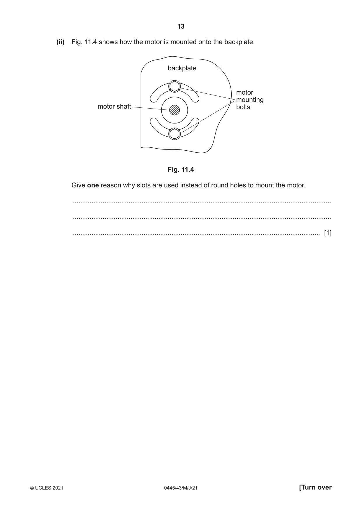
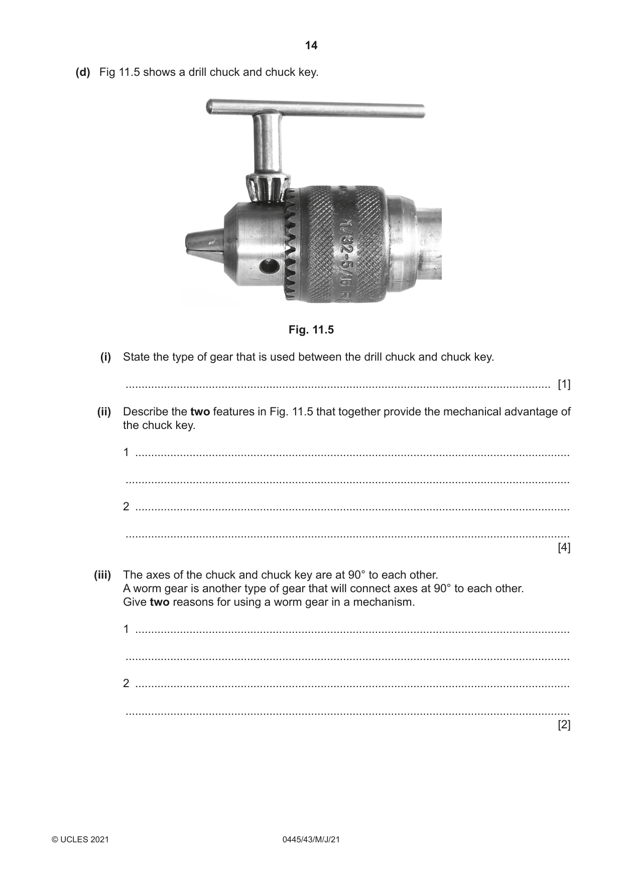
11 (a) (i) Use sketches and notes to show the meaning of the term ‘dwell’ in a cam. [2] (ii) Fig. 11.1 shows the profile of a cam and a follower. roller follower cam Fig. 11.1 Describe the movement of the follower for one rotation of the cam. ........................................................................................................................................... ........................................................................................................................................... ..................................................................................................................................... [2] (iii) Give one benefit of using a roller follower for this cam. ........................................................................................................................................... ..................................................................................................................................... [1] (b) Fig. 11.2 shows a ratchet and pawl mechanism used to tension a fence wire. fence wire tapered square head Fig. 11.2 (i) Explain how a ratchet and pawl mechanism operates. ........................................................................................................................................... ........................................................................................................................................... ........................................................................................................................................... ..................................................................................................................................... [3] (ii) Use sketches and notes to show a design for a tool suitable for turning the tapered square head on the mechanism. [3] (iii) Give one possible reason for the taper on the square head. ........................................................................................................................................... ..................................................................................................................................... [1] (iv) Describe how the tension in the fence wire can be released. ........................................................................................................................................... ........................................................................................................................................... ..................................................................................................................................... [2] (c) Fig 11.3 shows a compound pulley system that transfers drive from an electric motor to a small lathe. The system uses two belts. Ø22 motor Ø66 backplate Ø22 lathe Ø66 Fig. 11.3 (i) Calculate the output speed to the lathe with the belts in the position shown. The motor is turning at 1215 rpm. ........................................................................................................................................... ........................................................................................................................................... ........................................................................................................................................... ..................................................................................................................................... [3] (ii) Fig. 11.4 shows how the motor is mounted onto the backplate. backplate motor mounting motor shaft bolts Fig. 11.4 Give one reason why slots are used instead of round holes to mount the motor. ........................................................................................................................................... ........................................................................................................................................... ..................................................................................................................................... [1] (d) Fig 11.5 shows a drill chuck and chuck key. Fig. 11.5 (i) State the type of gear that is used between the drill chuck and chuck key. ..................................................................................................................................... [1] (ii) Describe the two features in Fig. 11.5 that together provide the mechanical advantage of the chuck key. 1 ........................................................................................................................................ ........................................................................................................................................... 2 ........................................................................................................................................ ........................................................................................................................................... [4] (iii) The axes of the chuck and chuck key are at 90° to each other. A worm gear is another type of gear that will connect axes at 90° to each other. Give two reasons for using a worm gear in a mechanism. 1 ........................................................................................................................................ ........................................................................................................................................... 2 ........................................................................................................................................ ........................................................................................................................................... [2]
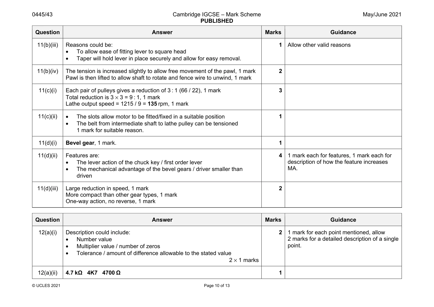
Mark scheme: 11(a)(i) Drawing of a cam with dwell clearly shown, 1 mark Label to indicate position of dwell, 1 mark. 2 11(a)(ii) • The follower will rise four times, 1 mark • The follower will fall four times, 1 mark • The rise and fall are the same distance each time, 1 mark • Mention of reciprocating motion, 1 mark • There is no dwell, 1 mark. 2 × 1 marks 2 Any two points included for 2 marks. 11(a)(iii) • The roller can follow the complete profile of the cam • Roller follower will reduce friction between cam and follower • A flat ended follower may bridge each of the lowest points 1 mark for suitable benefit. 1 Allow any other valid response 11(b)(i) Explanation should include: • It is a one-way mechanism • Pawl will drop into place through gravity or spring action • The pawl prevents reverse movement of the ratchet. 3 Two points mentioned for 2 marks. Allow 2 marks for a single point fully explained. No mark for ‘can apply tension’. 11(b)(ii) • Suitable size of tool / length of lever shown to give MA • Suitable width of lever in comparison to square head. • Square hole in one end of lever 3 Question Answer Marks Guidance 11(b)(iii) Reasons could be: • To allow ease of fitting lever to square head • Taper will hold lever in place securely and allow for easy removal. 1 Allow other valid reasons 11(b)(iv) The tension is increased slightly to allow free movement of the pawl, 1 mark Pawl is then lifted to allow shaft to rotate and fence wire to unwind, 1 mark 2 11(c)(i) Each pair of pulleys gives a reduction of 3 : 1 (66 / 22), 1 mark Total reduction is 3 × 3 = 9 : 1, 1 mark Lathe output speed = 1215 / 9 = 135 rpm, 1 mark 3 11(c)(ii) • The slots allow motor to be fitted/fixed in a suitable position • The belt from intermediate shaft to lathe pulley can be tensioned 1 mark for suitable reason. 1 11(d)(i) Bevel gear, 1 mark. 1 11(d)(ii) Features are: • The lever action of the chuck key / first order lever • The mechanical advantage of the bevel gears / driver smaller than driven 4 1 mark each for features, 1 mark each for description of how the feature increases MA. 11(d)(iii) Large reduction in speed, 1 mark More compact than other gear types, 1 mark One-way action, no reverse, 1 mark 2
Q12 · A resistor colour code chart and a fixed resistor
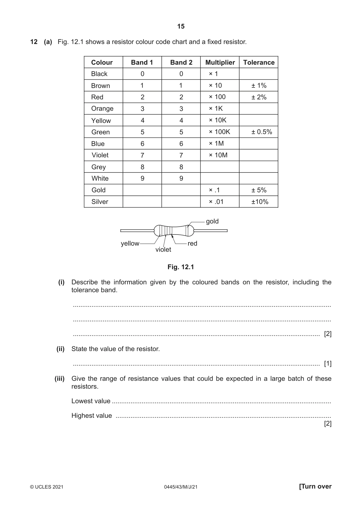
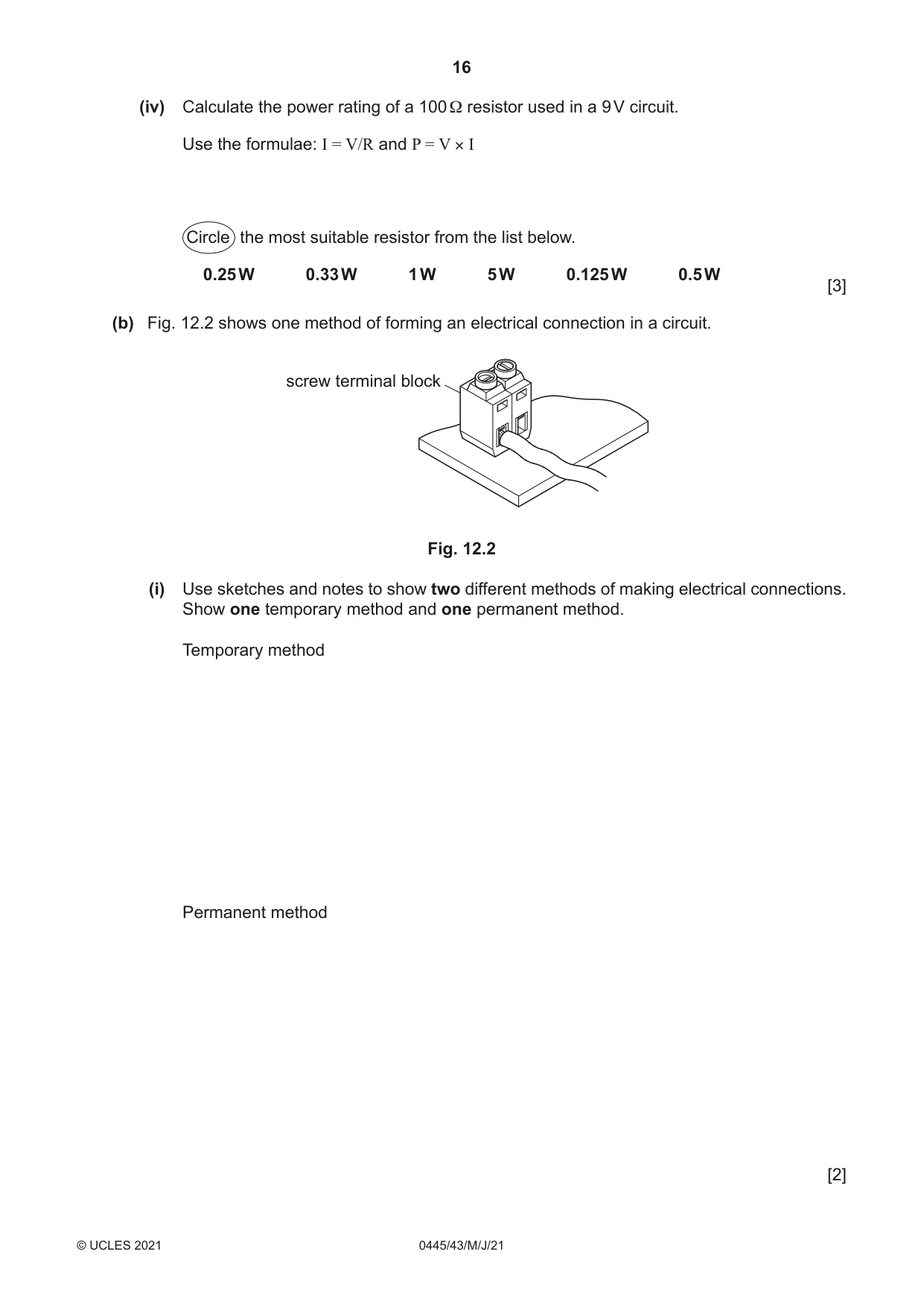
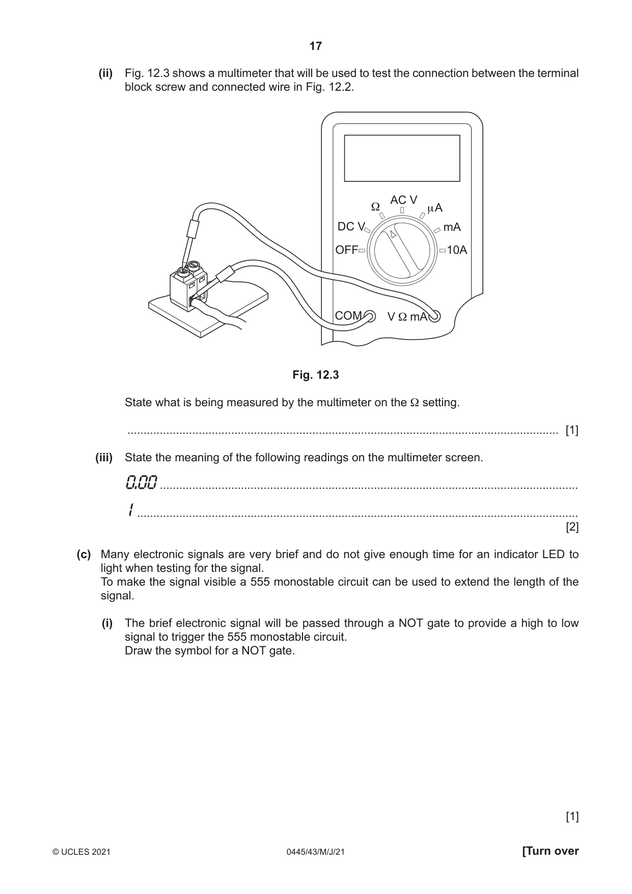
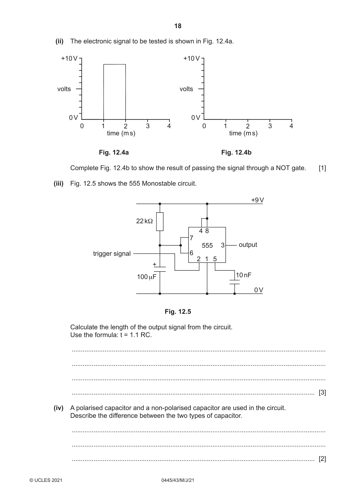
12 (a) Fig. 12.1 shows a resistor colour code chart and a fixed resistor. Colour Band 1 Band 2 Multiplier Tolerance Black 0 0 × 1 Brown 1 1 × 10 ± 1% Red 2 2 × 100 ± 2% Orange 3 3 × 1K Yellow 4 4 × 10K Green 5 5 × 100K ± 0.5% Blue 6 6 × 1M Violet 7 7 × 10M Grey 8 8 White 9 9 Gold × .1 ± 5% Silver × .01 ±10% gold yellow red violet Fig. 12.1 (i) Describe the information given by the coloured bands on the resistor, including the tolerance band. ........................................................................................................................................... ........................................................................................................................................... ..................................................................................................................................... [2] (ii) State the value of the resistor. ..................................................................................................................................... [1] (iii) Give the range of resistance values that could be expected in a large batch of these resistors. Lowest value ...................................................................................................................... Highest value .................................................................................................................... [2] (iv) Calculate the power rating of a 100 Ω resistor used in a 9 V circuit. Use the formulae: I = V/R and P = V × I Circle the most suitable resistor from the list below. 0.25 W 0.33 W 1 W 5 W 0.125 W 0.5 W [3] (b) Fig. 12.2 shows one method of forming an electrical connection in a circuit. screw terminal block Fig. 12.2 (i) Use sketches and notes to show two different methods of making electrical connections. Show one temporary method and one permanent method. Temporary method Permanent method [2] (ii) Fig. 12.3 shows a multimeter that will be used to test the connection between the terminal block screw and connected wire in Fig. 12.2. AC V Ω μ A DC V mA OFF 10A COM V Ω mA Fig. 12.3 State what is being measured by the multimeter on the Ω setting. ..................................................................................................................................... [1] (iii) State the meaning of the following readings on the multimeter screen. 0.00................................................................................................................................. 1........................................................................................................................................ [2] (c) Many electronic signals are very brief and do not give enough time for an indicator LED to light when testing for the signal. To make the signal visible a 555 monostable circuit can be used to extend the length of the signal. (i) The brief electronic signal will be passed through a NOT gate to provide a high to low signal to trigger the 555 monostable circuit. Draw the symbol for a NOT gate. [1]
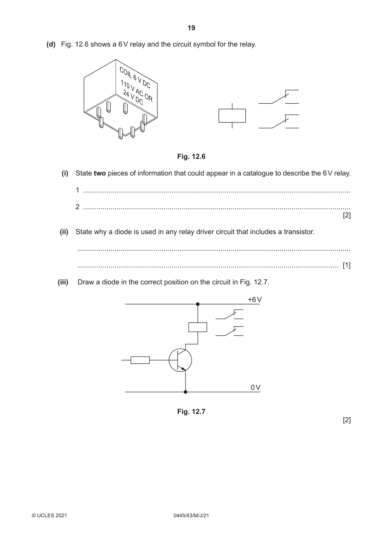
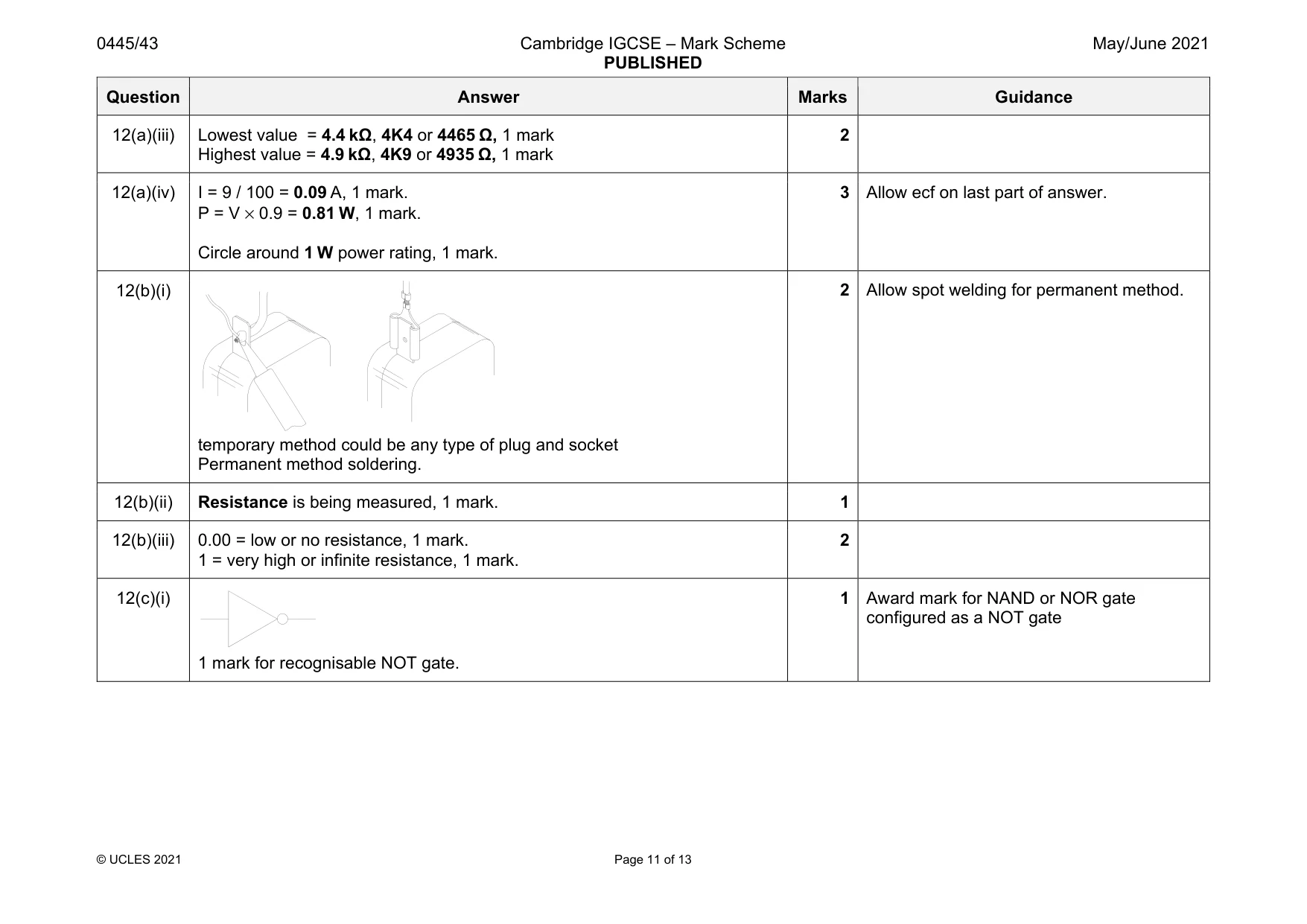
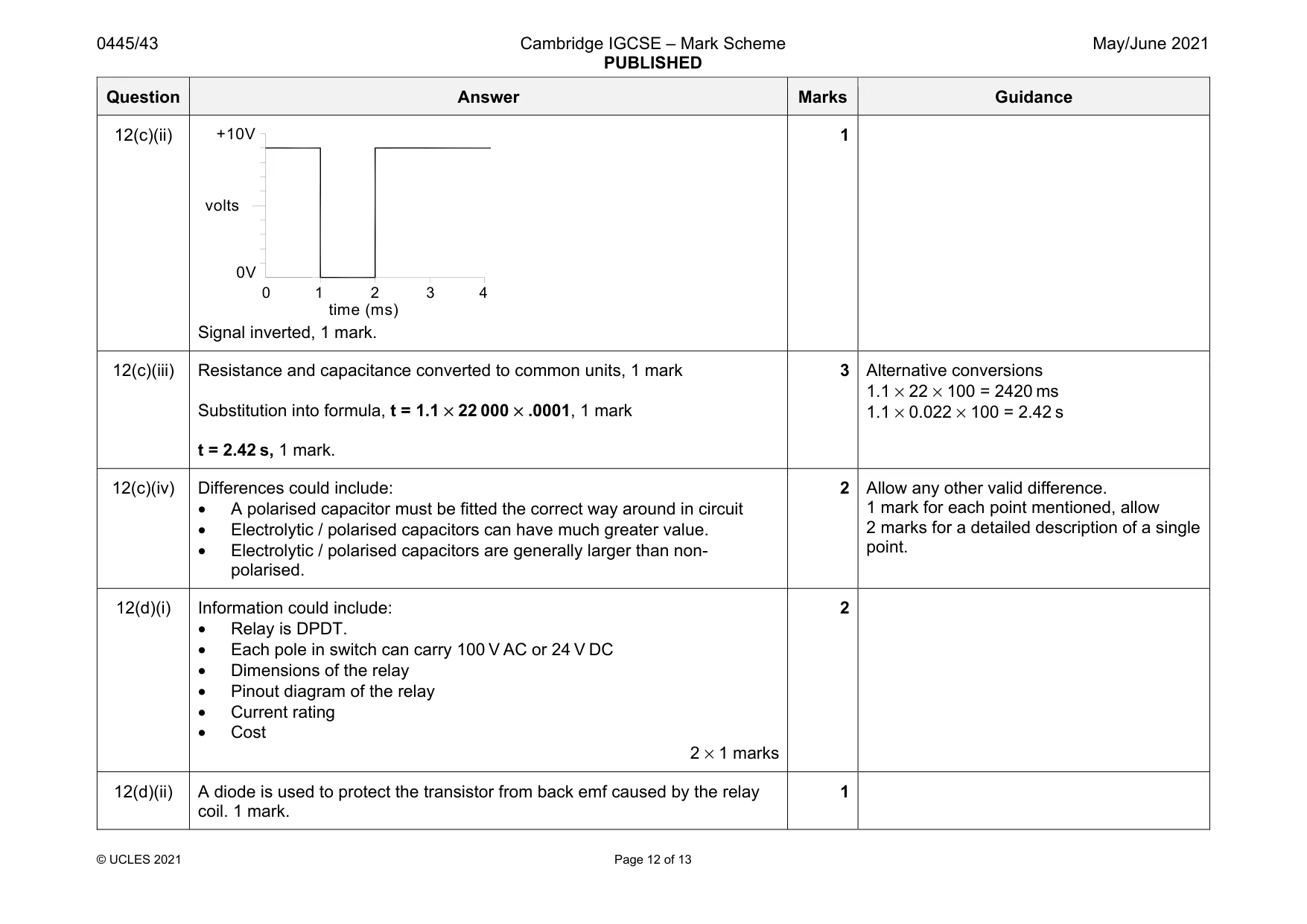
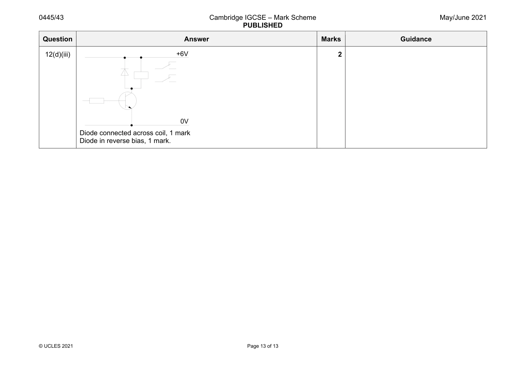
Mark scheme: 12(a)(i) Description could include: • Number value • Multiplier value / number of zeros • Tolerance / amount of difference allowable to the stated value 2 × 1 marks 2 marks for a detailed description of a single point. 12(a)(ii) 4.7 kΩ 4K7 4700 Ω 1 Question Answer Marks Guidance 12(a)(iii) Lowest value = 4.4 kΩ, 4K4 or 4465 Ω, 1 mark Highest value = 4.9 kΩ, 4K9 or 4935 Ω, 1 mark 2 12(a)(iv) I = 9 / 100 = 0.09 A, 1 mark. P = V × 0.9 = 0.81 W, 1 mark. Circle around 1 W power rating, 1 mark. 3 Allow ecf on last part of answer. 12(b)(i) temporary method could be any type of plug and socket Permanent method soldering. 2 Allow spot welding for permanent method. 12(b)(ii) Resistance is being measured, 1 mark. 1 12(b)(iii) 0.00 = low or no resistance, 1 mark. 1 = very high or infinite resistance, 1 mark. 2 12(c)(i) 1 mark for recognisable NOT gate. 1 Award mark for NAND or NOR gate configured as a NOT gate Question Answer Marks Guidance 12(c)(ii) Signal inverted, 1 mark. 1 12(c)(iii) Resistance and capacitance converted to common units, 1 mark Substitution into formula, t = 1.1 × 22 000 × .0001, 1 mark t = 2.42 s, 1 mark. 3 Alternative conversions 1.1 × 22 × 100 = 2420 ms 1.1 × 0.022 × 100 = 2.42 s 12(c)(iv) Differences could include: • A polarised capacitor must be fitted the correct way around in circuit • Electrolytic / polarised capacitors can have much greater value. • Electrolytic / polarised capacitors are generally larger than non- polarised. 2 Allow any other valid difference. 1 mark for each point mentioned, allow 2 marks for a detailed description of a single point. 12(d)(i) Information could include: • Relay is DPDT. • Each pole in switch can carry 100 V AC or 24 V DC • Dimensions of the relay • Pinout diagram of the relay • Current rating • Cost 2 × 1 marks 2 12(d)(ii) A diode is used to protect the transistor from back emf caused by the relay coil. 1 mark. 1 0V +10V time (ms) volts 1 2 3 4 0 Question Answer Marks Guidance 12(d)(iii) Diode connected across coil, 1 mark Diode in reverse bias, 1 mark. 2 +6V 0V
What was in this paper
The subtopics covered by these 12 questions, and how many questions each got. Open one in a new tab to see every Cambridge question on it.
What you needed in this session
Cambridge’s own grade thresholds for 2021 May/June, Paper 4 · Variant 3. A higher threshold means an easier paper — the bar moves with how the cohort did.