Cambridge IGCSE Design and Technology 0445 — 2021 May/June Paper 4 · Variant 2
0445/42/M/J/21 · 12 questions · 50 marks · ≈56 min
The question paper and its mark scheme, free to read here and free to download. This is Cambridge’s own paper, exactly as it was sat.
Question paper20 pages


Mark scheme11 pages
Answers below. Sit the paper first if you are practising.
Questions as text
Q1 · Identify two renewable energy sources from the list below
1 Identify two renewable energy sources from the list below. oil solar natural gas nuclear hydroelectric 1 ....................................................................................................................................................... 2 ....................................................................................................................................................... [2]
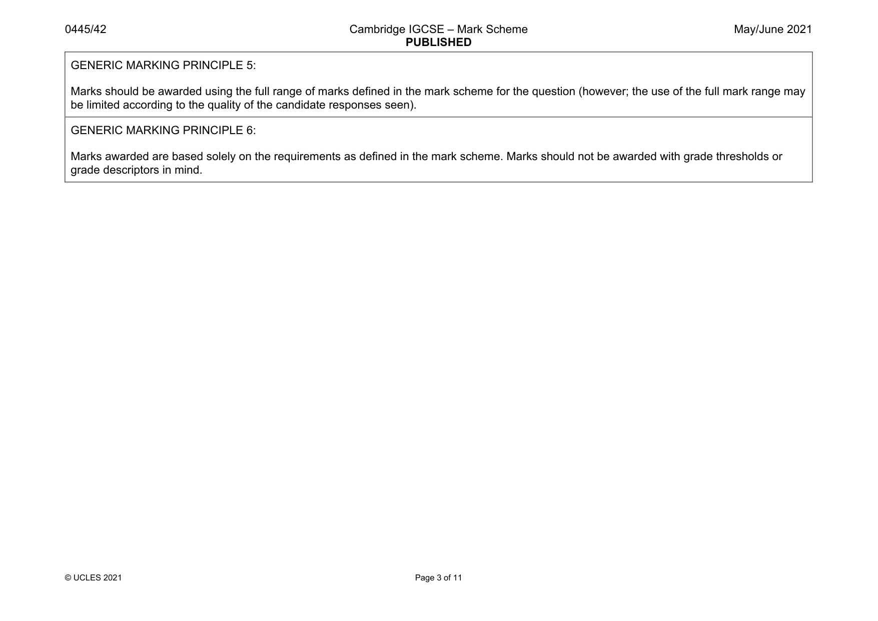
Mark scheme: 1 Solar, 1 mark. Hydroelectric, 1 mark. 2
Q2 · Give one example of a manufacturing machine that can be controlled by computer
2 (a) Give one example of a manufacturing machine that can be controlled by computer. ............................................................................................................................................. [1] (b) Describe two benefits of using computer controlled machines. ................................................................................................................................................... ................................................................................................................................................... ................................................................................................................................................... ............................................................................................................................................. [2]
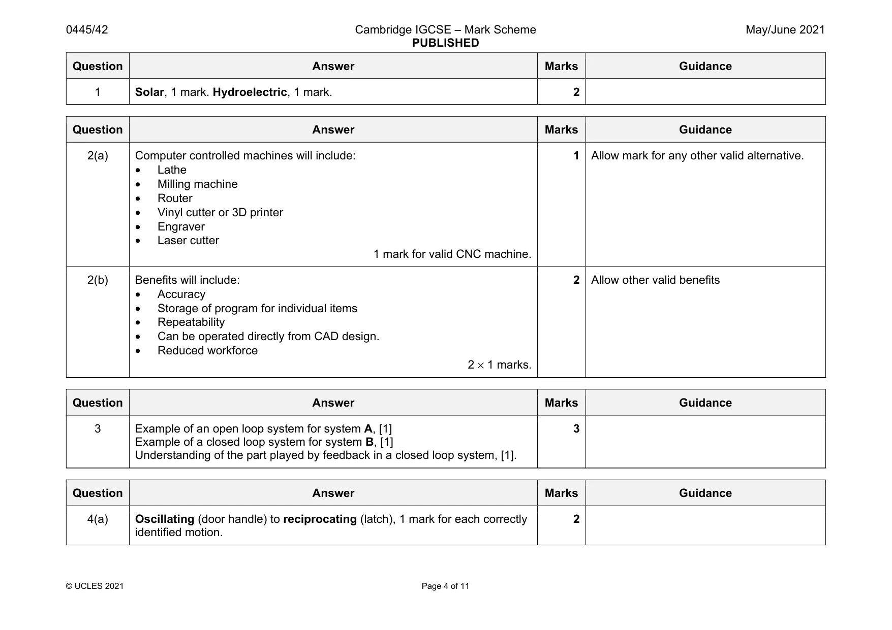
Mark scheme: 2(a) Computer controlled machines will include: • Lathe • Milling machine • Router • Vinyl cutter or 3D printer • Engraver • Laser cutter 1 mark for valid CNC machine. 1 Allow mark for any other valid alternative. 2(b) Benefits will include: • Accuracy • Storage of program for individual items • Repeatability • Can be operated directly from CAD design. • Reduced workforce 2 × 1 marks. 2 Allow other valid benefits
Q3 · Block diagrams of two types of control system
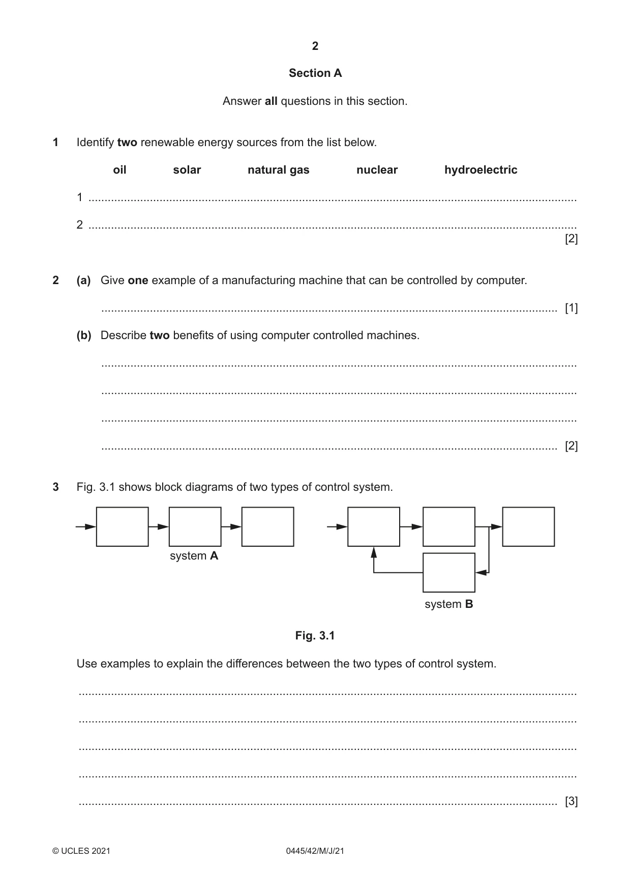
3 Fig. 3.1 shows block diagrams of two types of control system. system A system B Fig. 3.1 Use examples to explain the differences between the two types of control system. .......................................................................................................................................................... .......................................................................................................................................................... .......................................................................................................................................................... .......................................................................................................................................................... .................................................................................................................................................... [3]
Mark scheme: 3 Example of an open loop system for system A, [1] Example of a closed loop system for system B, [1] Understanding of the part played by feedback in a closed loop system, [1]. 3
Q4 · A door handle and latch
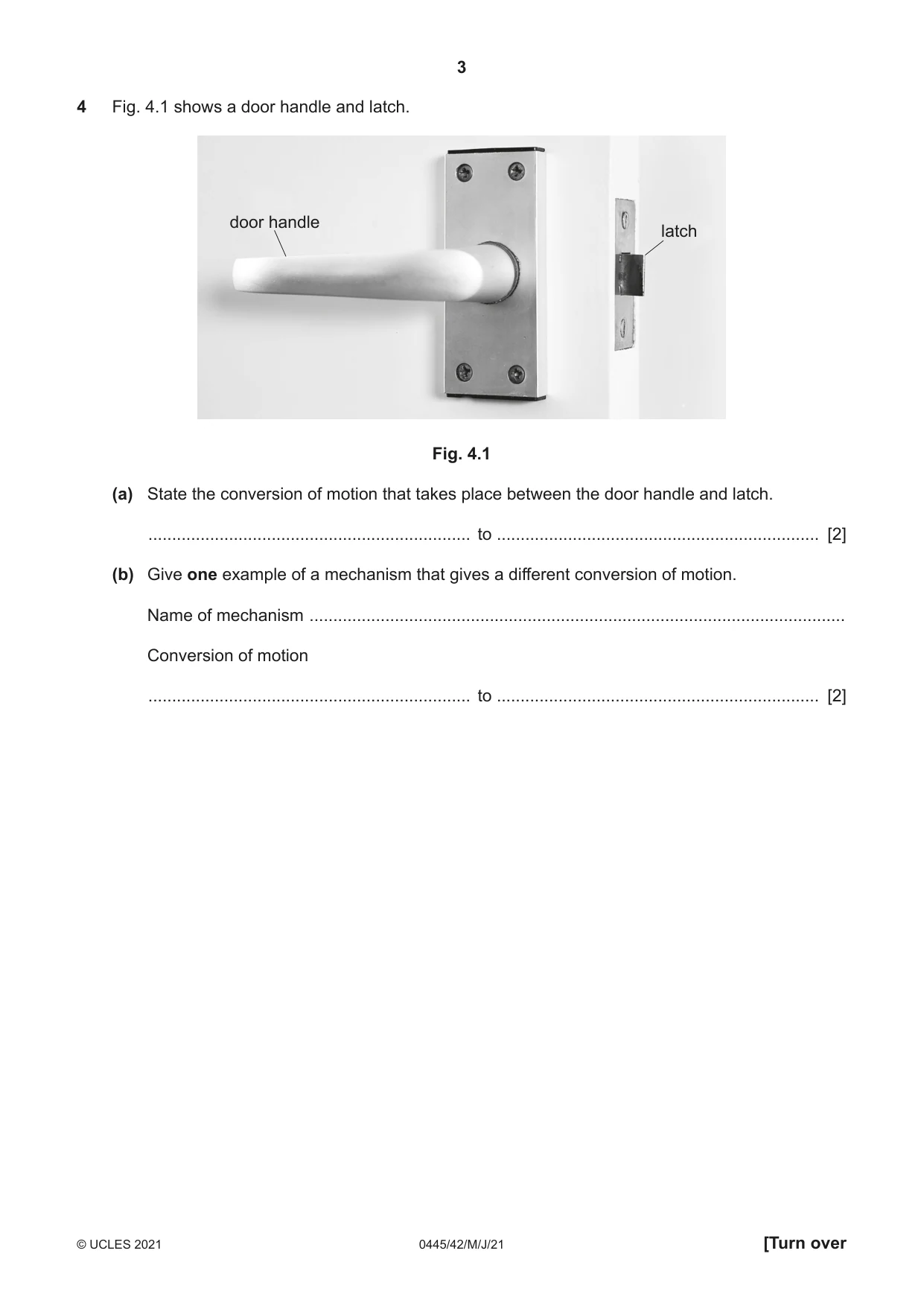
4 Fig. 4.1 shows a door handle and latch. door handle latch Fig. 4.1 (a) State the conversion of motion that takes place between the door handle and latch. .................................................................... to .................................................................... [2] (b) Give one example of a mechanism that gives a different conversion of motion. Name of mechanism ................................................................................................................. Conversion of motion .................................................................... to .................................................................... [2]
Mark scheme: 4(a) Oscillating (door handle) to reciprocating (latch), 1 mark for each correctly identified motion. 2 Question Answer Marks Guidance 4(b) Input motion identified 1 mark. Output motion identified, 1 mark. 2 No marks for name of mechanism Conversion must match mechanism.
Q5 · A series of spur gears in a machine
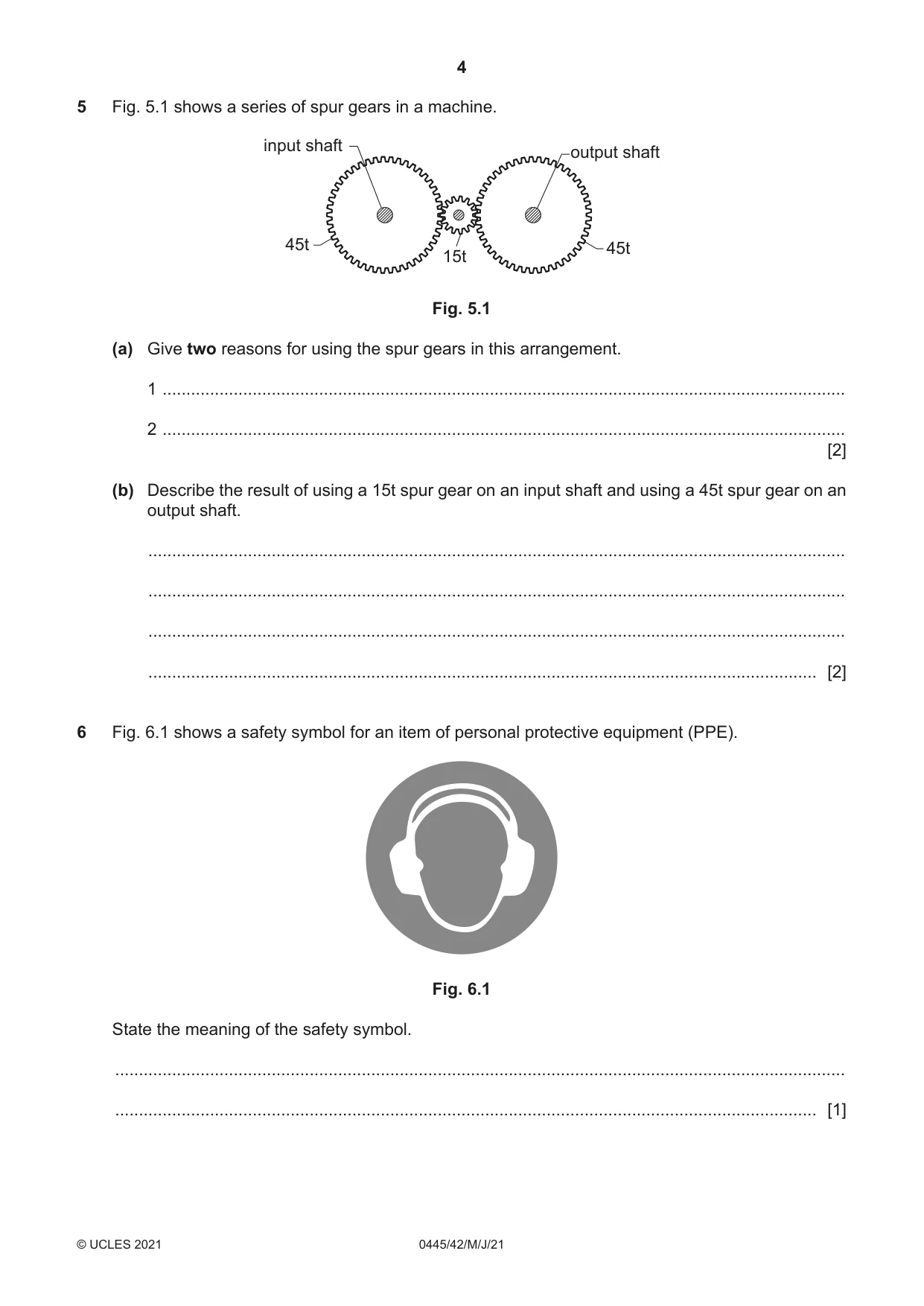
5 Fig. 5.1 shows a series of spur gears in a machine. input shaft output shaft 45t 45t 15t Fig. 5.1 (a) Give two reasons for using the spur gears in this arrangement. 1 ................................................................................................................................................ 2 ................................................................................................................................................ [2] (b) Describe the result of using a 15t spur gear on an input shaft and using a 45t spur gear on an output shaft. ................................................................................................................................................... ................................................................................................................................................... ................................................................................................................................................... ............................................................................................................................................. [2]
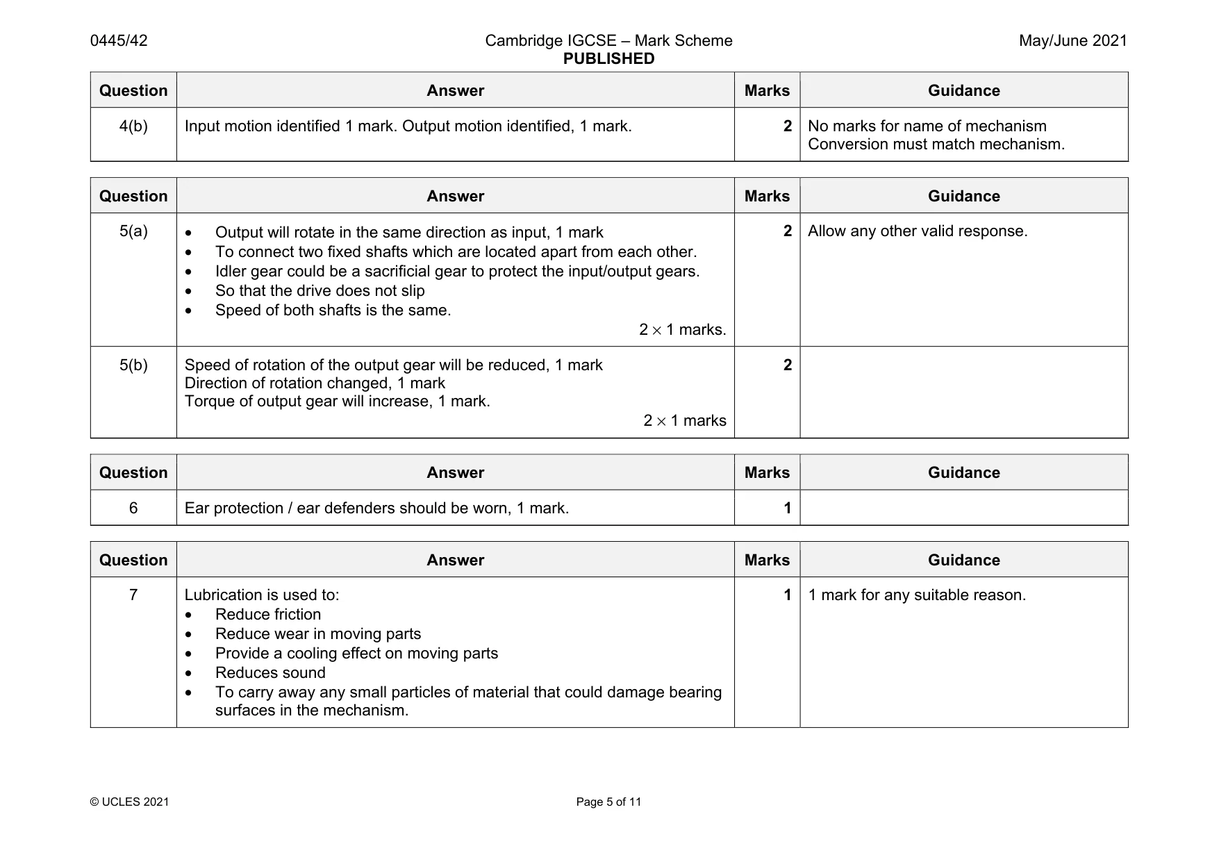
Mark scheme: 5(a) • Output will rotate in the same direction as input, 1 mark • To connect two fixed shafts which are located apart from each other. • Idler gear could be a sacrificial gear to protect the input/output gears. • So that the drive does not slip • Speed of both shafts is the same. 2 × 1 marks. 2 Allow any other valid response. 5(b) Speed of rotation of the output gear will be reduced, 1 mark Direction of rotation changed, 1 mark Torque of output gear will increase, 1 mark. 2 × 1 marks 2
Q6 · A safety symbol for an item of personal protective equipment (PPE)
6 Fig. 6.1 shows a safety symbol for an item of personal protective equipment (PPE). Fig. 6.1 State the meaning of the safety symbol. .......................................................................................................................................................... .................................................................................................................................................... [1]
Mark scheme: 6 Ear protection / ear defenders should be worn, 1 mark. 1
Q7 · Give one reason why lubrication is important in mechanisms
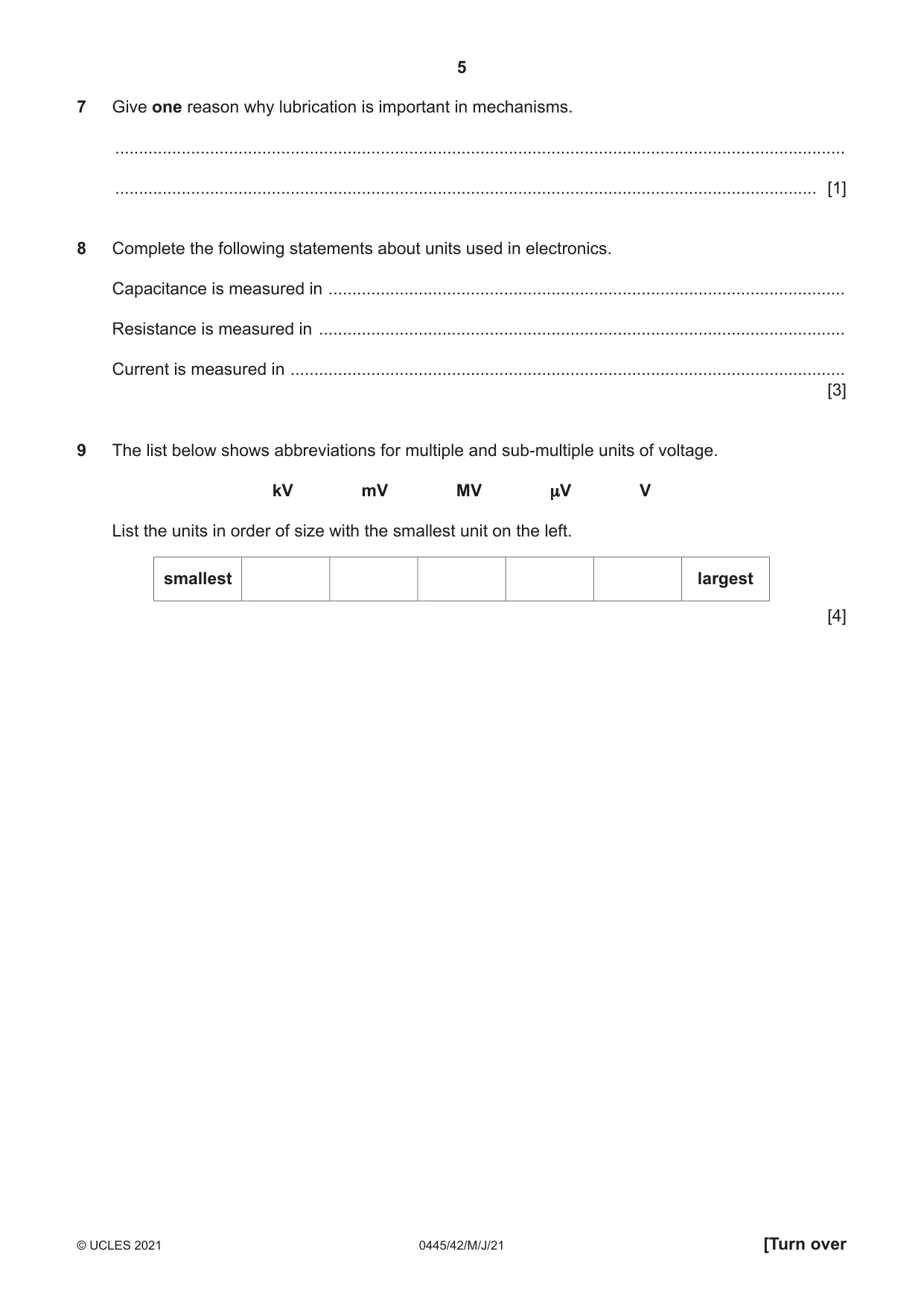
7 Give one reason why lubrication is important in mechanisms. .......................................................................................................................................................... .................................................................................................................................................... [1]
Mark scheme: 7 Lubrication is used to: • Reduce friction • Reduce wear in moving parts • Provide a cooling effect on moving parts • Reduces sound • To carry away any small particles of material that could damage bearing surfaces in the mechanism.
Q8 · Complete the following statements about units used in electronics
8 Complete the following statements about units used in electronics. Capacitance is measured in ............................................................................................................. Resistance is measured in ............................................................................................................... Current is measured in ..................................................................................................................... [3]
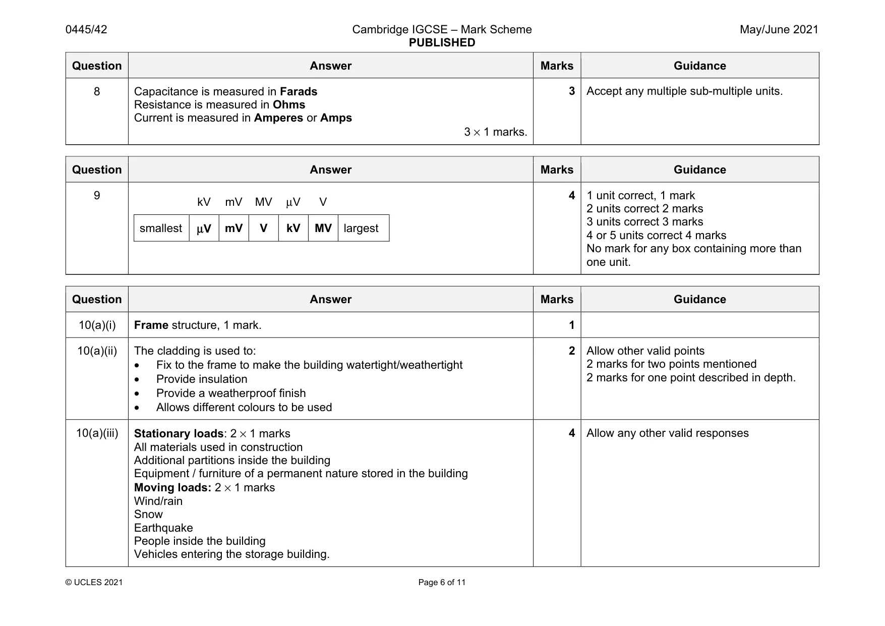
Mark scheme: 8 Capacitance is measured in Farads Resistance is measured in Ohms Current is measured in Amperes or Amps 3 × 1 marks.
Q9 · The list below shows abbreviations for multiple and sub‑multiple units of voltage
9 The list below shows abbreviations for multiple and sub‑multiple units of voltage. kV mV MV μV V List the units in order of size with the smallest unit on the left. smallest largest [4]
Mark scheme: 9 kV mV MV μV V smallest μV mV V kV MV largest 4 1 unit correct, 1 mark 2 units correct 2 marks 3 units correct 3 marks 4 or 5 units correct 4 marks No mark for any box containing more than one unit.
Q10 · A building under construction
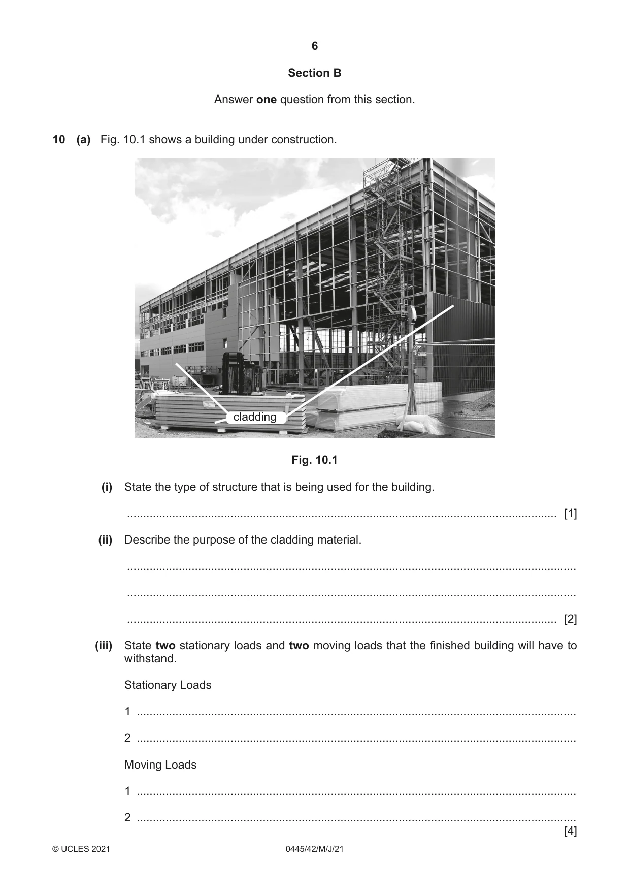
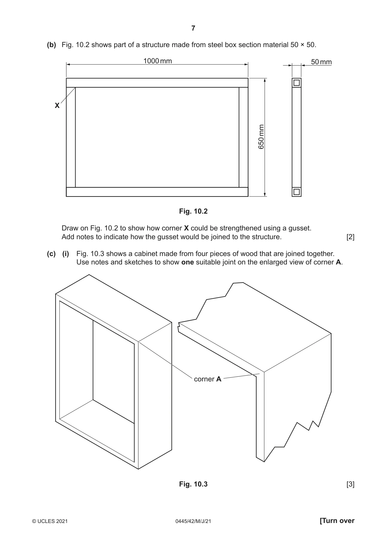
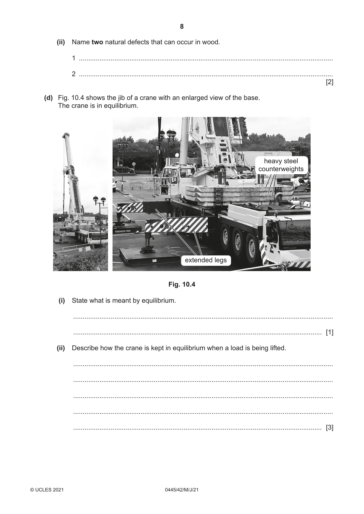
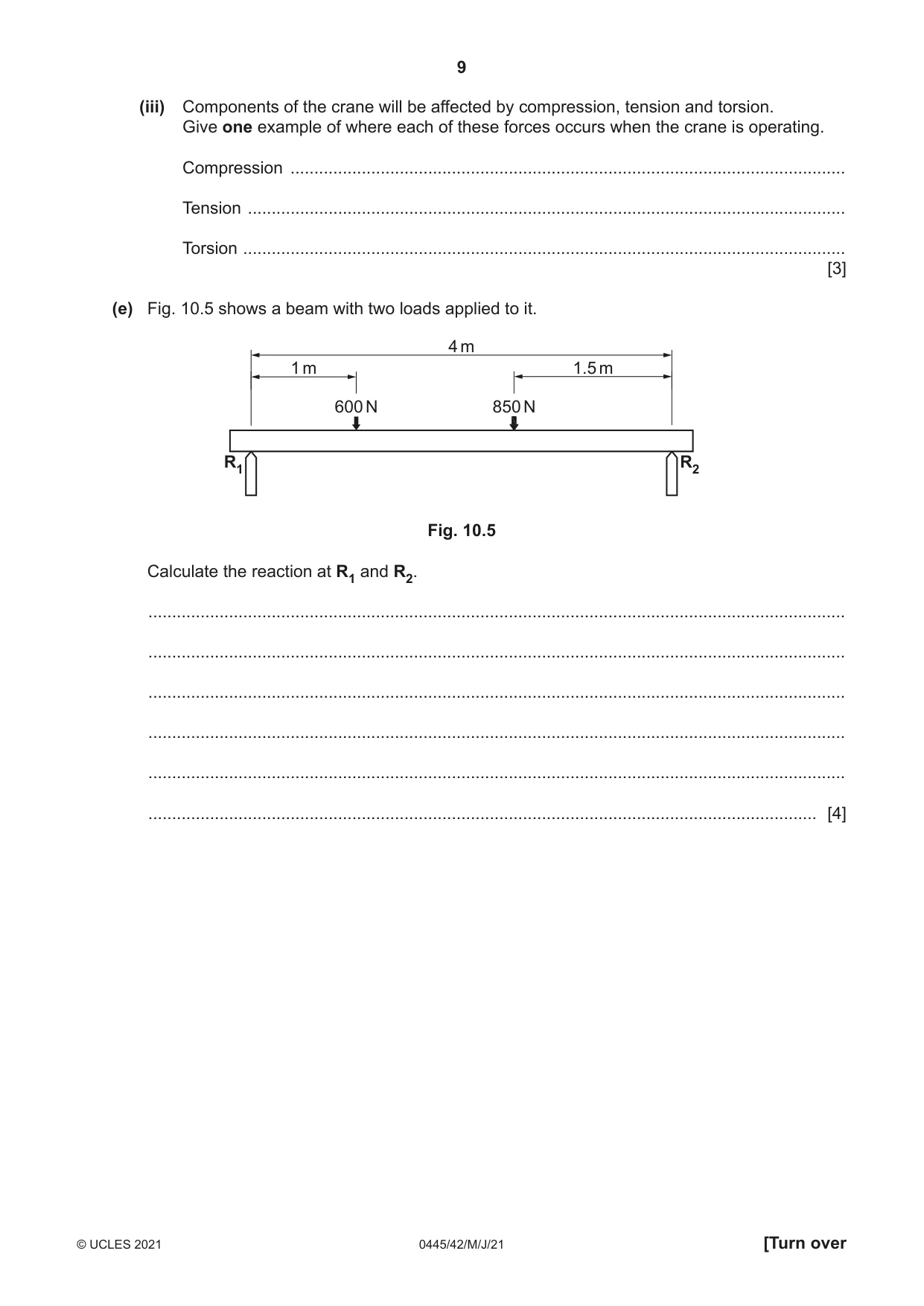
10 (a) Fig. 10.1 shows a building under construction. cladding Fig. 10.1 (i) State the type of structure that is being used for the building. ..................................................................................................................................... [1] (ii) Describe the purpose of the cladding material. ........................................................................................................................................... ........................................................................................................................................... ..................................................................................................................................... [2] (iii) State two stationary loads and two moving loads that the finished building will have to withstand. Stationary Loads 1 ........................................................................................................................................ 2 ........................................................................................................................................ Moving Loads 1 ........................................................................................................................................ 2 ........................................................................................................................................ [4] (b) Fig. 10.2 shows part of a structure made from steel box section material 50 × 50. 1000 mm 50 mm X mm 650 Fig. 10.2 Draw on Fig. 10.2 to show how corner X could be strengthened using a gusset. Add notes to indicate how the gusset would be joined to the structure. [2] (c) (i) Fig. 10.3 shows a cabinet made from four pieces of wood that are joined together. Use notes and sketches to show one suitable joint on the enlarged view of corner A. corner A Fig. 10.3 [3] (ii) Name two natural defects that can occur in wood. 1 ........................................................................................................................................ 2 ........................................................................................................................................ [2] (d) Fig. 10.4 shows the jib of a crane with an enlarged view of the base. The crane is in equilibrium. heavy steel counterweights extended legs Fig. 10.4 (i) State what is meant by equilibrium. ........................................................................................................................................... ..................................................................................................................................... [1] (ii) Describe how the crane is kept in equilibrium when a load is being lifted. ........................................................................................................................................... ........................................................................................................................................... ........................................................................................................................................... ........................................................................................................................................... ..................................................................................................................................... [3] (iii) Components of the crane will be affected by compression, tension and torsion. Give one example of where each of these forces occurs when the crane is operating. Compression ..................................................................................................................... Tension .............................................................................................................................. Torsion ............................................................................................................................... [3] (e) Fig. 10.5 shows a beam with two loads applied to it. 4 m 1 m 1.5 m 600 N 850 N R1 R2 Fig. 10.5 Calculate the reaction at R1 and R2. ................................................................................................................................................... ................................................................................................................................................... ................................................................................................................................................... ................................................................................................................................................... ................................................................................................................................................... ............................................................................................................................................. [4]
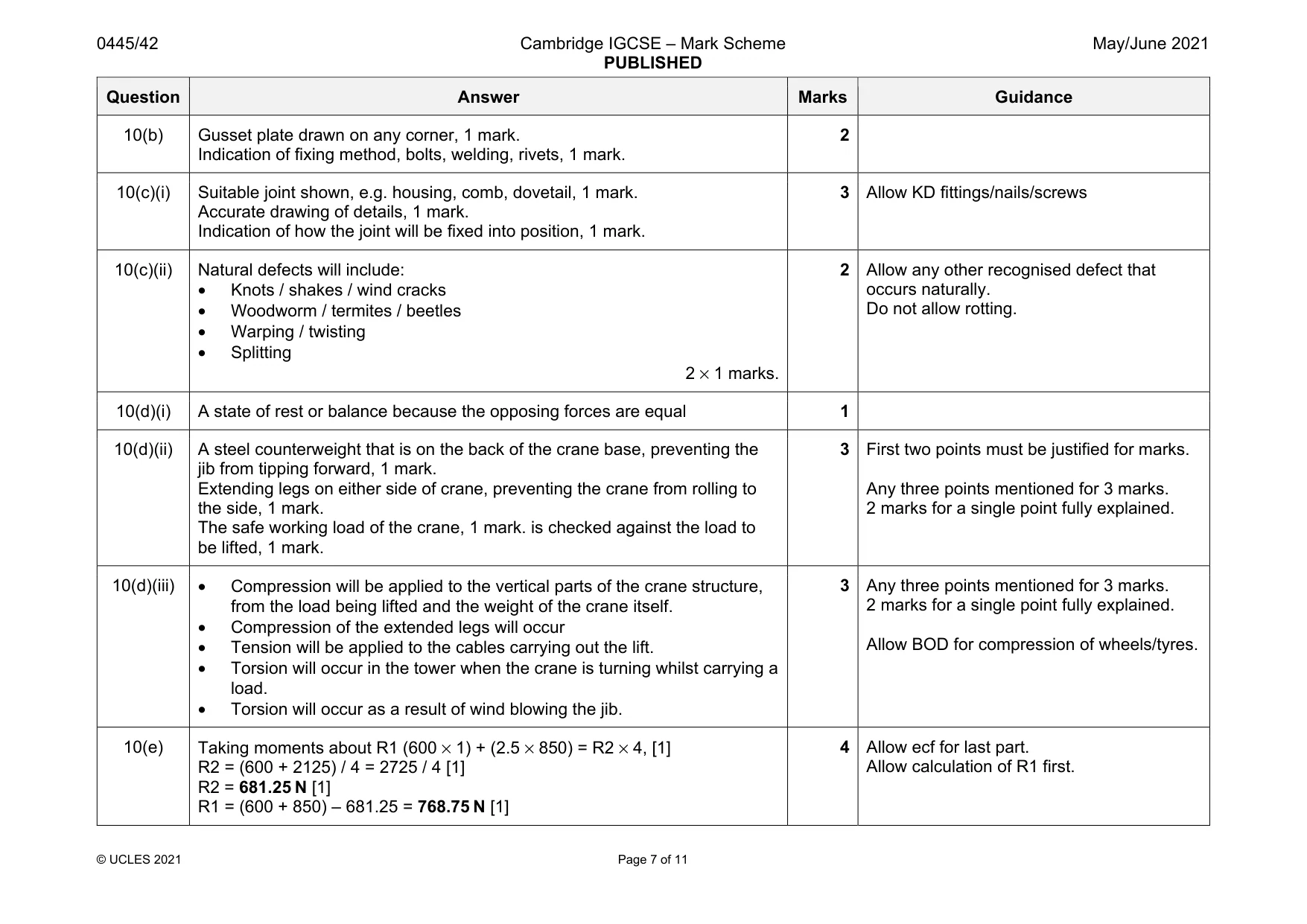
Mark scheme: 10(a)(i) Frame structure, 1 mark. 1 10(a)(ii) The cladding is used to: • Fix to the frame to make the building watertight/weathertight • Provide insulation • Provide a weatherproof finish • Allows different colours to be used 2 Allow other valid points 2 marks for two points mentioned 2 marks for one point described in depth. 10(a)(iii) Stationary loads: 2 × 1 marks All materials used in construction Additional partitions inside the building Equipment / furniture of a permanent nature stored in the building Moving loads: 2 × 1 marks Wind/rain Snow Earthquake People inside the building Vehicles entering the storage building. 4 Allow any other valid responses Question Answer Marks Guidance 10(b) Gusset plate drawn on any corner, 1 mark. Indication of fixing method, bolts, welding, rivets, 1 mark. 2 10(c)(i) Suitable joint shown, e.g. housing, comb, dovetail, 1 mark. Accurate drawing of details, 1 mark. Indication of how the joint will be fixed into position, 1 mark. 3 Allow KD fittings/nails/screws 10(c)(ii) Natural defects will include: • Knots / shakes / wind cracks • Woodworm / termites / beetles • Warping / twisting • Splitting 2 × 1 marks. 2 Allow any other recognised defect that occurs naturally. Do not allow rotting. 10(d)(i) A state of rest or balance because the opposing forces are equal 1 10(d)(ii) A steel counterweight that is on the back of the crane base, preventing the jib from tipping forward, 1 mark. Extending legs on either side of crane, preventing the crane from rolling to the side, 1 mark. The safe working load of the crane, 1 mark. is checked against the load to be lifted, 1 mark. 3 First two points must be justified for marks. Any three points mentioned for 3 marks. 2 marks for a single point fully explained. 10(d)(iii) • Compression will be applied to the vertical parts of the crane structure, from the load being lifted and the weight of the crane itself. • Compression of the extended legs will occur • Tension will be applied to the cables carrying out the lift. • Torsion will occur in the tower when the crane is turning whilst carrying a load. • Torsion will occur as a result of wind blowing the jib. 3 Any three points mentioned for 3 marks. 2 marks for a single point fully explained. Allow BOD for compression of wheels/tyres. 10(e) Taking moments about R1 (600 × 1) + (2.5 × 850) = R2 × 4, [1] R2 = (600 + 2125) / 4 = 2725 / 4 [1] R2 = 681.25 N [1] R1 = (600 + 850) – 681.25 = 768.75 N [1] 4 Allow ecf for last part. Allow calculation of R1 first.
Q11 · A belt and pulley system
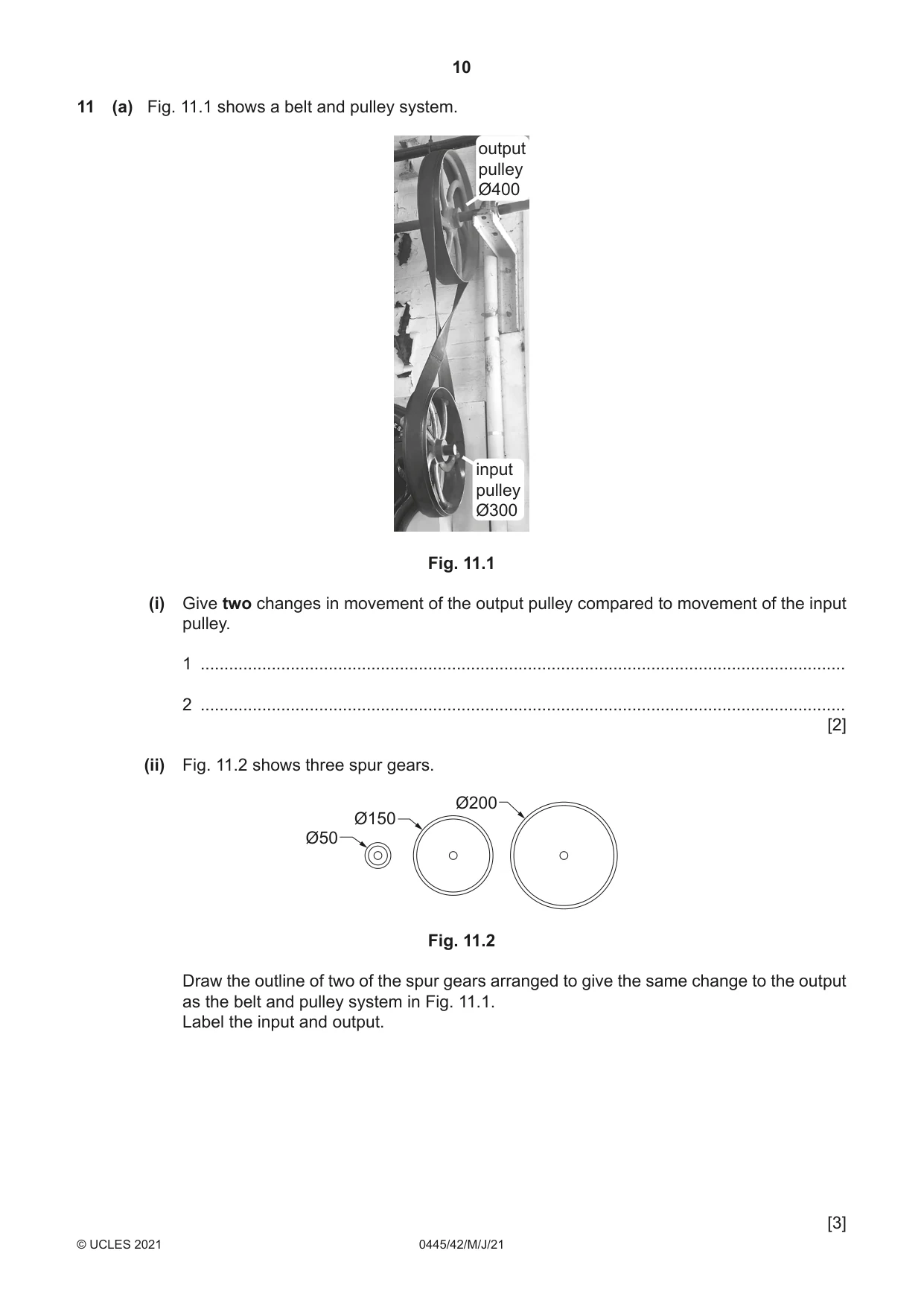
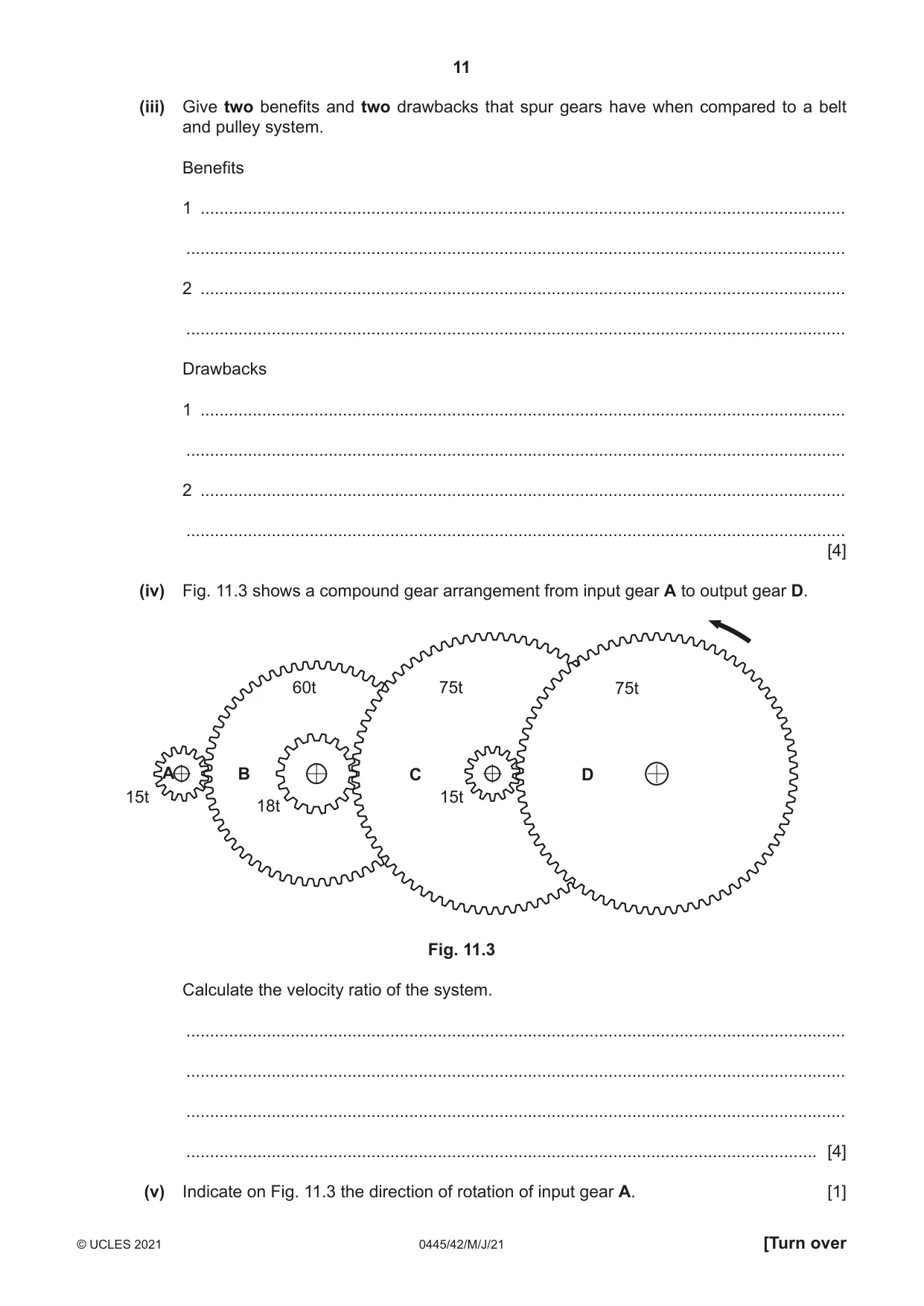
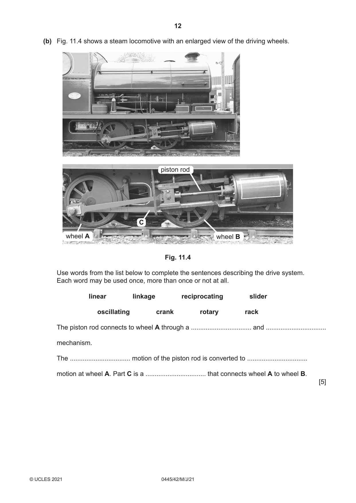
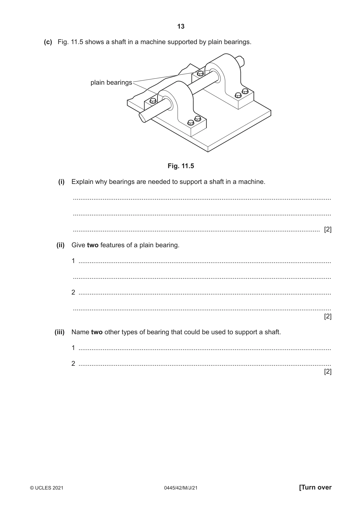
11 (a) Fig. 11.1 shows a belt and pulley system. output pulley Ø400 input pulley Ø300 Fig. 11.1 (i) Give two changes in movement of the output pulley compared to movement of the input pulley. 1 ........................................................................................................................................ 2 ........................................................................................................................................ [2] (ii) Fig. 11.2 shows three spur gears. Ø200 Ø150 Ø50 Fig. 11.2 Draw the outline of two of the spur gears arranged to give the same change to the output as the belt and pulley system in Fig. 11.1. Label the input and output. [3] (iii) Give two benefits and two drawbacks that spur gears have when compared to a belt and pulley system. Benefits 1 ........................................................................................................................................ ........................................................................................................................................... 2 ........................................................................................................................................ ........................................................................................................................................... Drawbacks 1 ........................................................................................................................................ ........................................................................................................................................... 2 ........................................................................................................................................ ........................................................................................................................................... [4] (iv) Fig. 11.3 shows a compound gear arrangement from input gear A to output gear D. 60t 75t 75t A B C D 15t 15t 18t Fig. 11.3 Calculate the velocity ratio of the system. ........................................................................................................................................... ........................................................................................................................................... ........................................................................................................................................... ..................................................................................................................................... [4] (v) Indicate on Fig. 11.3 the direction of rotation of input gear A. [1] (b) Fig. 11.4 shows a steam locomotive with an enlarged view of the driving wheels. piston rod C wheel A wheel B Fig. 11.4 Use words from the list below to complete the sentences describing the drive system. Each word may be used once, more than once or not at all. linear linkage reciprocating slider oscillating crank rotary rack The piston rod connects to wheel A through a ................................. and ................................. mechanism. The ................................. motion of the piston rod is converted to ................................. motion at wheel A. Part C is a ................................. that connects wheel A to wheel B. [5] (c) Fig. 11.5 shows a shaft in a machine supported by plain bearings. plain bearings Fig. 11.5 (i) Explain why bearings are needed to support a shaft in a machine. ........................................................................................................................................... ........................................................................................................................................... ..................................................................................................................................... [2] (ii) Give two features of a plain bearing. 1 ........................................................................................................................................ ........................................................................................................................................... 2 ........................................................................................................................................ ........................................................................................................................................... [2] (iii) Name two other types of bearing that could be used to support a shaft. 1 ........................................................................................................................................ 2 ........................................................................................................................................ [2]
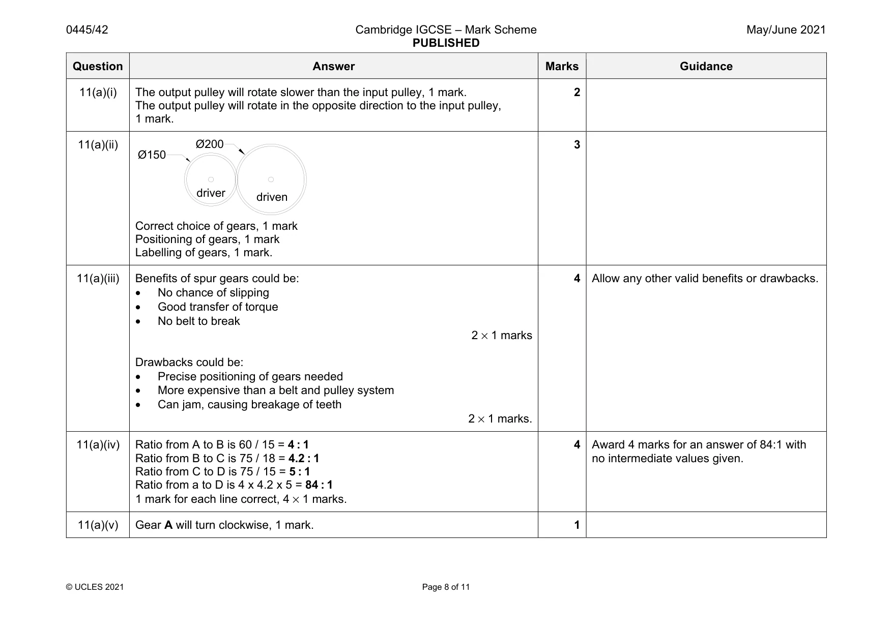
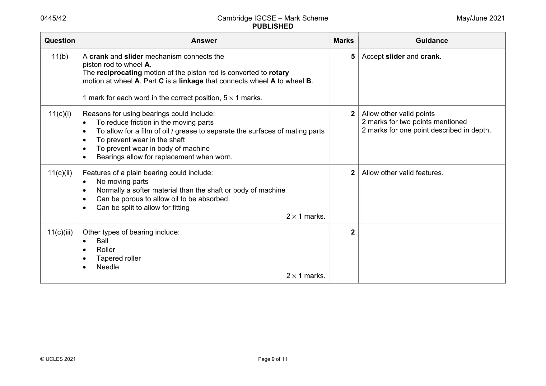
Mark scheme: 11(a)(i) The output pulley will rotate slower than the input pulley, 1 mark. The output pulley will rotate in the opposite direction to the input pulley, 1 mark. 2 11(a)(ii) Correct choice of gears, 1 mark Positioning of gears, 1 mark Labelling of gears, 1 mark. 3 11(a)(iii) Benefits of spur gears could be: • No chance of slipping • Good transfer of torque • No belt to break 2 × 1 marks Drawbacks could be: • Precise positioning of gears needed • More expensive than a belt and pulley system • Can jam, causing breakage of teeth 2 × 1 marks. 4 Allow any other valid benefits or drawbacks. 11(a)(iv) Ratio from A to B is 60 / 15 = 4 : 1 Ratio from B to C is 75 / 18 = 4.2 : 1 Ratio from C to D is 75 / 15 = 5 : 1 Ratio from a to D is 4 x 4.2 x 5 = 84 : 1 1 mark for each line correct, 4 × 1 marks. 4 Award 4 marks for an answer of 84:1 with no intermediate values given. 11(a)(v) Gear A will turn clockwise, 1 mark. 1 Ø150 Ø200 driver driven Question Answer Marks Guidance 11(b) A crank and slider mechanism connects the piston rod to wheel A. The reciprocating motion of the piston rod is converted to rotary motion at wheel A. Part C is a linkage that connects wheel A to wheel B. 1 mark for each word in the correct position, 5 × 1 marks. 5 Accept slider and crank. 11(c)(i) Reasons for using bearings could include: • To reduce friction in the moving parts • To allow for a film of oil / grease to separate the surfaces of mating parts • To prevent wear in the shaft • To prevent wear in body of machine • Bearings allow for replacement when worn. 2 Allow other valid points 2 marks for two points mentioned 2 marks for one point described in depth. 11(c)(ii) Features of a plain bearing could include: • No moving parts • Normally a softer material than the shaft or body of machine • Can be porous to allow oil to be absorbed. • Can be split to allow for fitting 2 × 1 marks. 2 Allow other valid features. 11(c)(iii) Other types of bearing include: • Ball • Roller • Tapered roller • Needle 2 × 1 marks. 2
Q12 · The list below shows different stages in the production of an electronic circuit
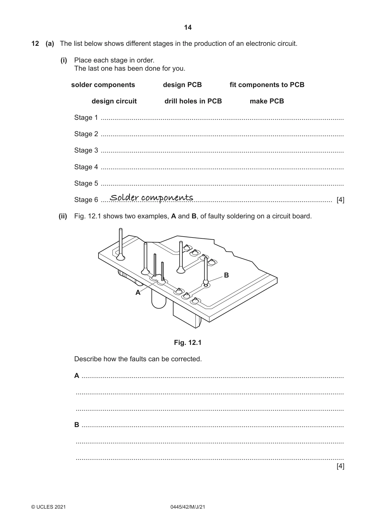
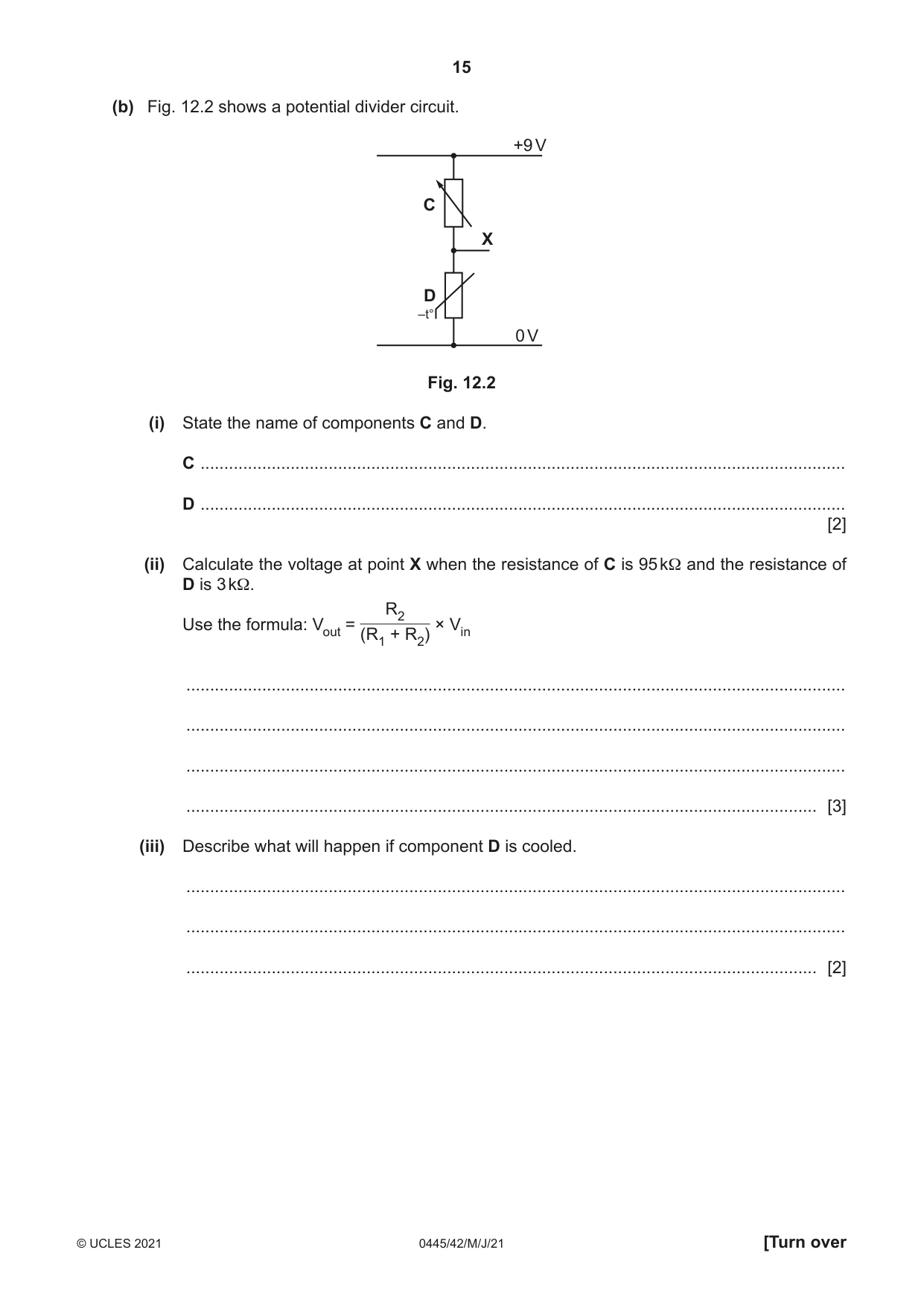
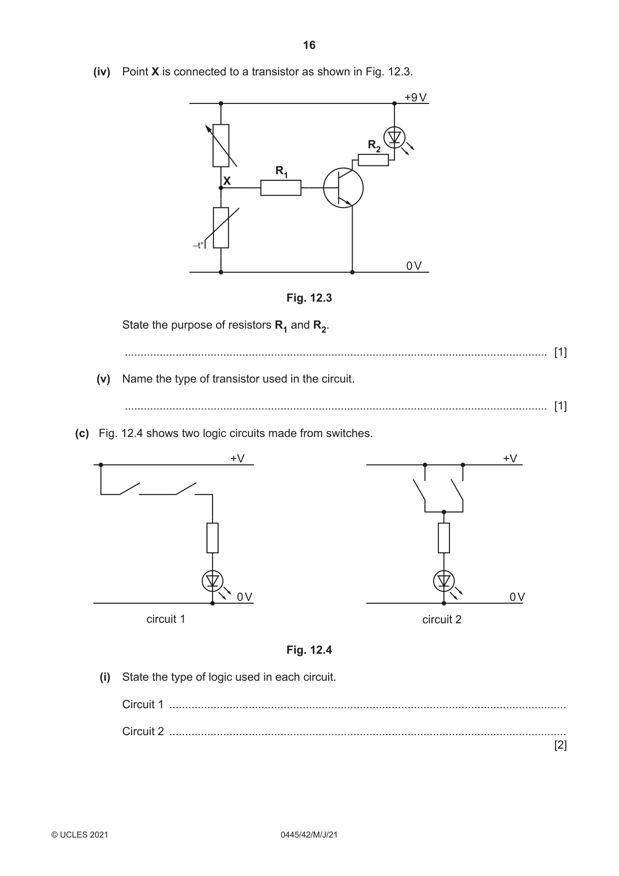
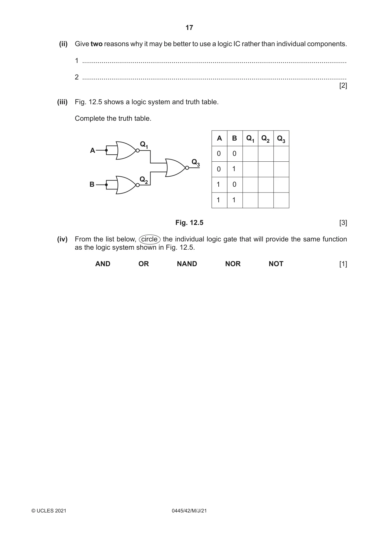
12 (a) The list below shows different stages in the production of an electronic circuit. (i) Place each stage in order. The last one has been done for you. solder components design PCB fit components to PCB design circuit drill holes in PCB make PCB Stage 1 .............................................................................................................................. Stage 2 .............................................................................................................................. Stage 3 .............................................................................................................................. Stage 4 .............................................................................................................................. Stage 5 .............................................................................................................................. Stage 6 ........................................................................................................................Solder components [4] (ii) Fig. 12.1 shows two examples, A and B, of faulty soldering on a circuit board. B A Fig. 12.1 Describe how the faults can be corrected. A ........................................................................................................................................ ........................................................................................................................................... ........................................................................................................................................... B ........................................................................................................................................ ........................................................................................................................................... ........................................................................................................................................... [4] (b) Fig. 12.2 shows a potential divider circuit. +9 V C X D –t° 0 V Fig. 12.2 (i) State the name of components C and D. C ........................................................................................................................................ D ........................................................................................................................................ [2] (ii) Calculate the voltage at point X when the resistance of C is 95 kΩ and the resistance of D is 3 kΩ. R2 Use the formula: Vout = × Vin (R1 + R2) ........................................................................................................................................... ........................................................................................................................................... ........................................................................................................................................... ..................................................................................................................................... [3] (iii) Describe what will happen if component D is cooled. ........................................................................................................................................... ........................................................................................................................................... ..................................................................................................................................... [2] (iv) Point X is connected to a transistor as shown in Fig. 12.3. +9 V R2 R1 X –t° 0 V Fig. 12.3 State the purpose of resistors R1 and R2. ..................................................................................................................................... [1] (v) Name the type of transistor used in the circuit. ..................................................................................................................................... [1] (c) Fig. 12.4 shows two logic circuits made from switches. +V +V 0 V 0 V circuit 1 circuit 2 Fig. 12.4 (i) State the type of logic used in each circuit. Circuit 1 ............................................................................................................................. Circuit 2 ............................................................................................................................. [2]
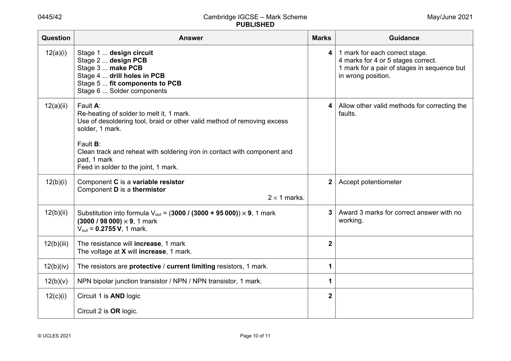
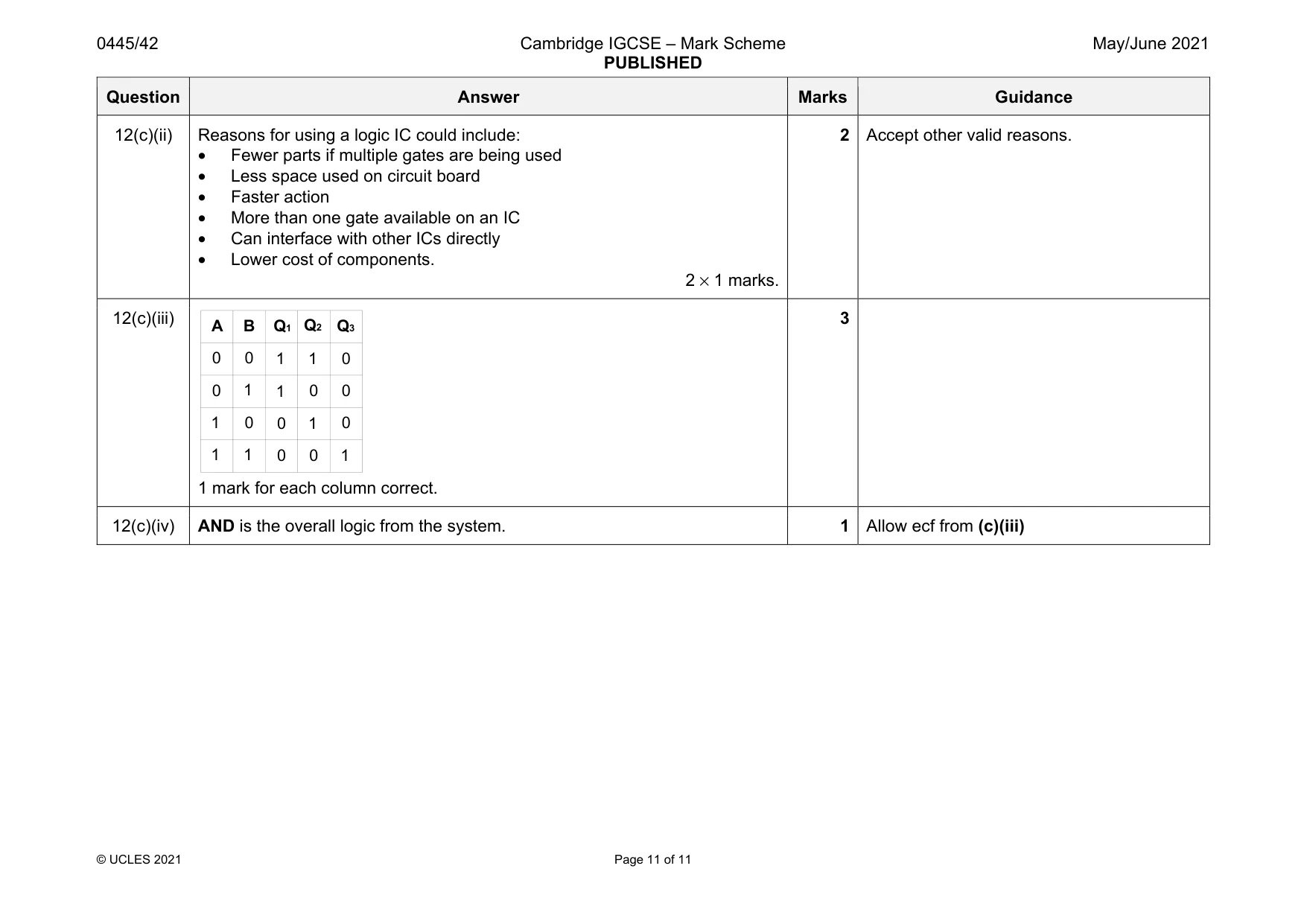
Mark scheme: 12(a)(i) Stage 1 ... design circuit Stage 2 ... design PCB Stage 3 ... make PCB Stage 4 ... drill holes in PCB Stage 5 ... fit components to PCB Stage 6 ... Solder components 4 1 mark for each correct stage. 4 marks for 4 or 5 stages correct. 1 mark for a pair of stages in sequence but in wrong position. 12(a)(ii) Fault A: Re-heating of solder to melt it, 1 mark. Use of desoldering tool, braid or other valid method of removing excess solder, 1 mark. Fault B: Clean track and reheat with soldering iron in contact with component and pad, 1 mark Feed in solder to the joint, 1 mark. 4 Allow other valid methods for correcting the faults. 12(b)(i) Component C is a variable resistor Component D is a thermistor 2 × 1 marks. 2 Accept potentiometer 12(b)(ii) Substitution into formula Vout = (3000 / (3000 + 95 000)) × 9, 1 mark (3000 / 98 000) × 9, 1 mark Vout = 0.2755 V, 1 mark. 3 Award 3 marks for correct answer with no working. 12(b)(iii) The resistance will increase, 1 mark The voltage at X will increase, 1 mark. 2 12(b)(iv) The resistors are protective / current limiting resistors, 1 mark. 1 12(b)(v) NPN bipolar junction transistor / NPN / NPN transistor, 1 mark. 1 12(c)(i) Circuit 1 is AND logic Circuit 2 is OR logic. 2 Question Answer Marks Guidance 12(c)(ii) Reasons for using a logic IC could include: • Fewer parts if multiple gates are being used • Less space used on circuit board • Faster action • More than one gate available on an IC • Can interface with other ICs directly • Lower cost of components. 2 × 1 marks. 2 Accept other valid reasons. 12(c)(iii) 1 mark for each column correct. 3 12(c)(iv) AND is the overall logic from the system. 1 Allow ecf from (c)(iii) A B Q1 Q2 Q3 0 0 1 1 0 1 0 1 1 1 0 0 1 0 1 0 0 0 0 1
What was in this paper
The subtopics covered by these 12 questions, and how many questions each got. Open one in a new tab to see every Cambridge question on it.
What you needed in this session
Cambridge’s own grade thresholds for 2021 May/June, Paper 4 · Variant 2. A higher threshold means an easier paper — the bar moves with how the cohort did.