Cambridge IGCSE Design and Technology 0445 — 2020 May/June Paper 4 · Variant 2
0445/42/M/J/20 · 12 questions · 86 marks · ≈97 min
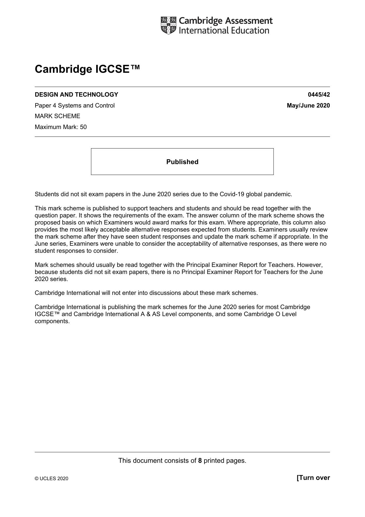
The question paper and its mark scheme, free to read here and free to download. This is Cambridge’s own paper, exactly as it was sat.
Question paper20 pages
Mark scheme8 pages
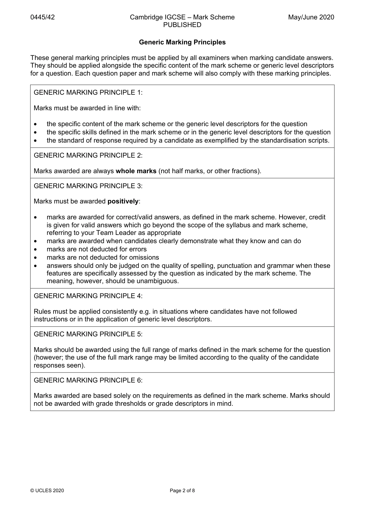
Answers below. Sit the paper first if you are practising.
Questions as text
Q1 · Give two advantages of using plastics rather than wood for making window and door frames
1 Give two advantages of using plastics rather than wood for making window and door frames. 1 ....................................................................................................................................................... .......................................................................................................................................................... 2 ....................................................................................................................................................... .......................................................................................................................................................... [2]
Mark scheme: Question Answer Marks 1 Advantages of plastics could be: 2 • Not affected by wet weather • Will not rot • Self-finishing • Can be moulded / extruded
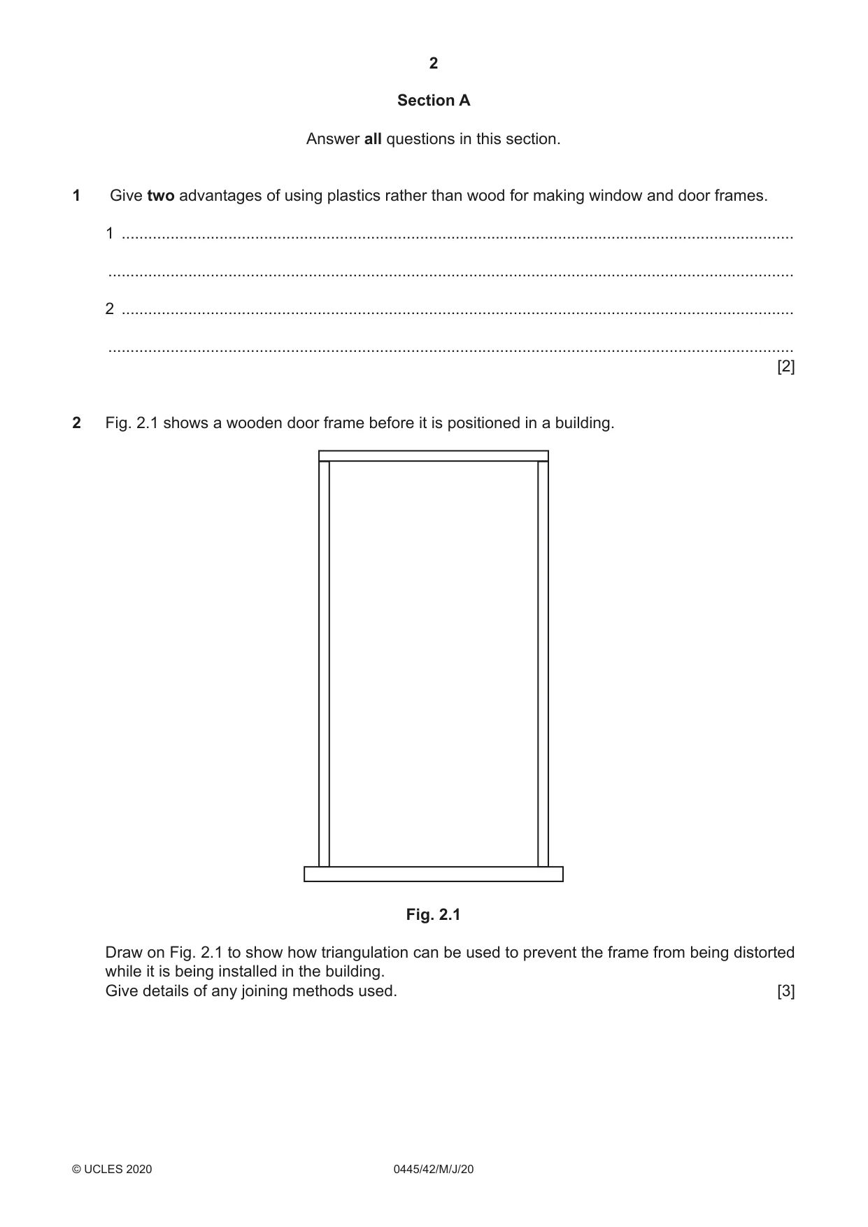
Q2 · A wooden door frame before it is positioned in a building
2 Fig. 2.1 shows a wooden door frame before it is positioned in a building. Fig. 2.1 Draw on Fig. 2.1 to show how triangulation can be used to prevent the frame from being distorted while it is being installed in the building. Give details of any joining methods used. [3]
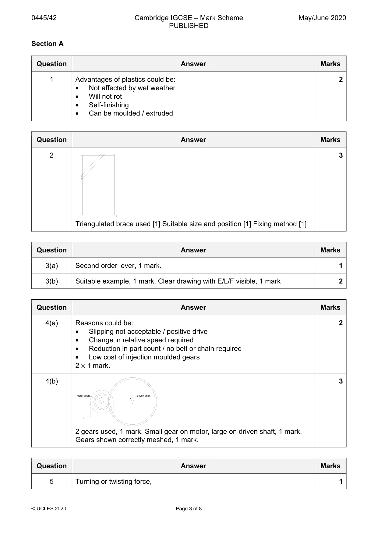
Mark scheme: 2 3 Triangulated brace used [1] Suitable size and position [1] Fixing method [1]
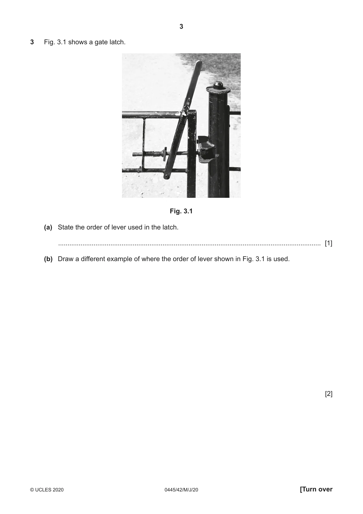
Question 3
3 Fig. 3.1 shows a gate latch. Fig. 3.1 (a) State the order of lever used in the latch. ............................................................................................................................................. [1] (b) Draw a different example of where the order of lever shown in Fig. 3.1 is used. [2]
Mark scheme: 3(a) Second order lever, 1 mark. 1 3(b) Suitable example, 1 mark. Clear drawing with E/L/F visible, 1 mark 2
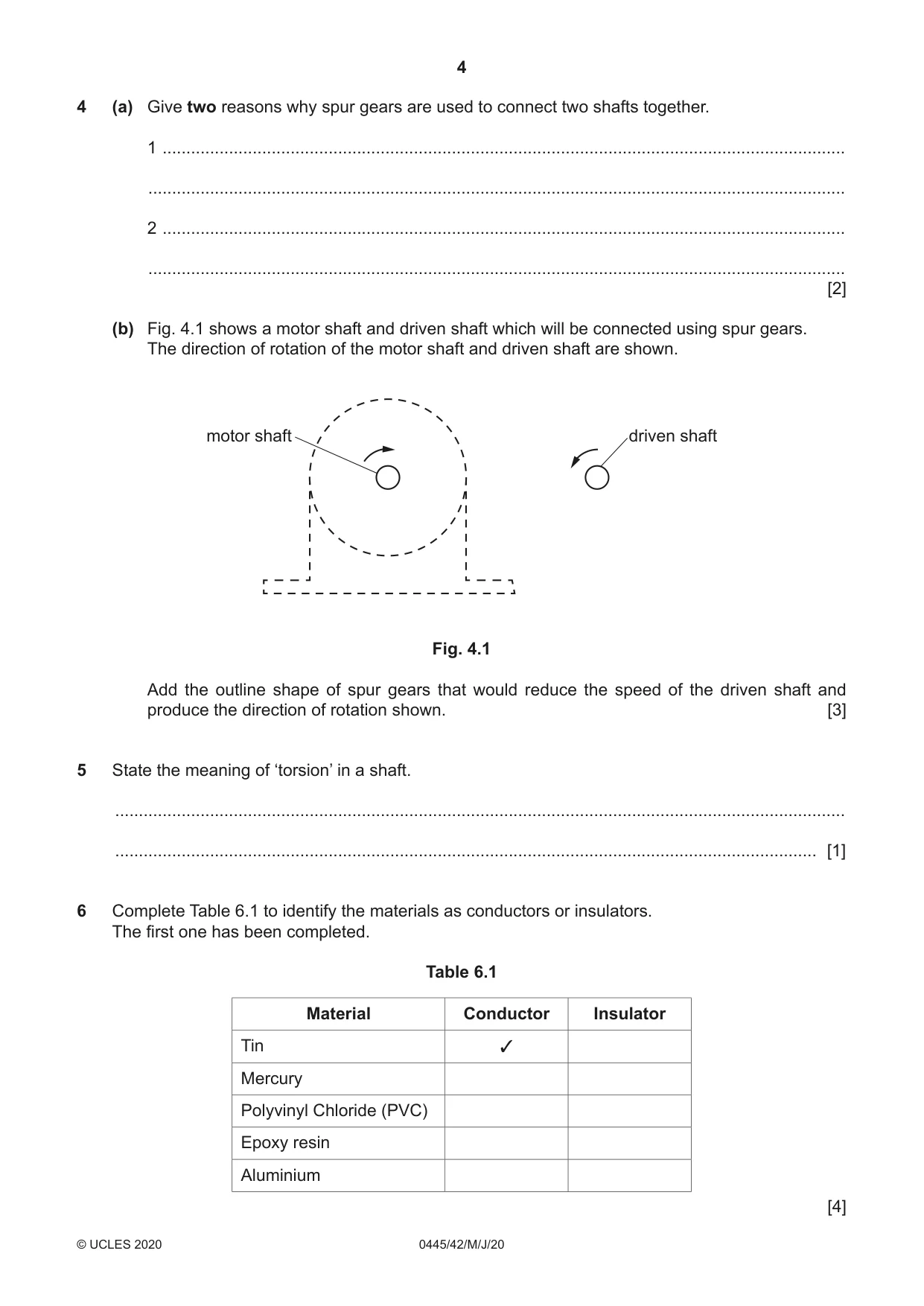
Q4 · Give two reasons why spur gears are used to connect two shafts together
4 (a) Give two reasons why spur gears are used to connect two shafts together. 1 ................................................................................................................................................ ................................................................................................................................................... 2 ................................................................................................................................................ ................................................................................................................................................... [2] (b) Fig. 4.1 shows a motor shaft and driven shaft which will be connected using spur gears. The direction of rotation of the motor shaft and driven shaft are shown. motor shaft driven shaft Fig. 4.1 Add the outline shape of spur gears that would reduce the speed of the driven shaft and produce the direction of rotation shown. [3]
Mark scheme: 4(a) Reasons could be: 2 • Slipping not acceptable / positive drive • Change in relative speed required • Reduction in part count / no belt or chain required • Low cost of injection moulded gears 2 × 1 mark. 4(b) 3 motor shaft driven shaft 2 gears used, 1 mark. Small gear on motor, large on driven shaft, 1 mark. Gears shown correctly meshed, 1 mark.
Q5 · State the meaning of ‘torsion’ in a shaft
5 State the meaning of ‘torsion’ in a shaft. .......................................................................................................................................................... .................................................................................................................................................... [1]
Mark scheme: 5 Turning or twisting force, 1
Q6 · Complete Table 6.1 to identify the materials as conductors or insulators
6 Complete Table 6.1 to identify the materials as conductors or insulators. The first one has been completed. Table 6.1 Material Conductor Insulator Tin ✓ Mercury Polyvinyl Chloride (PVC) Epoxy resin Aluminium [4]
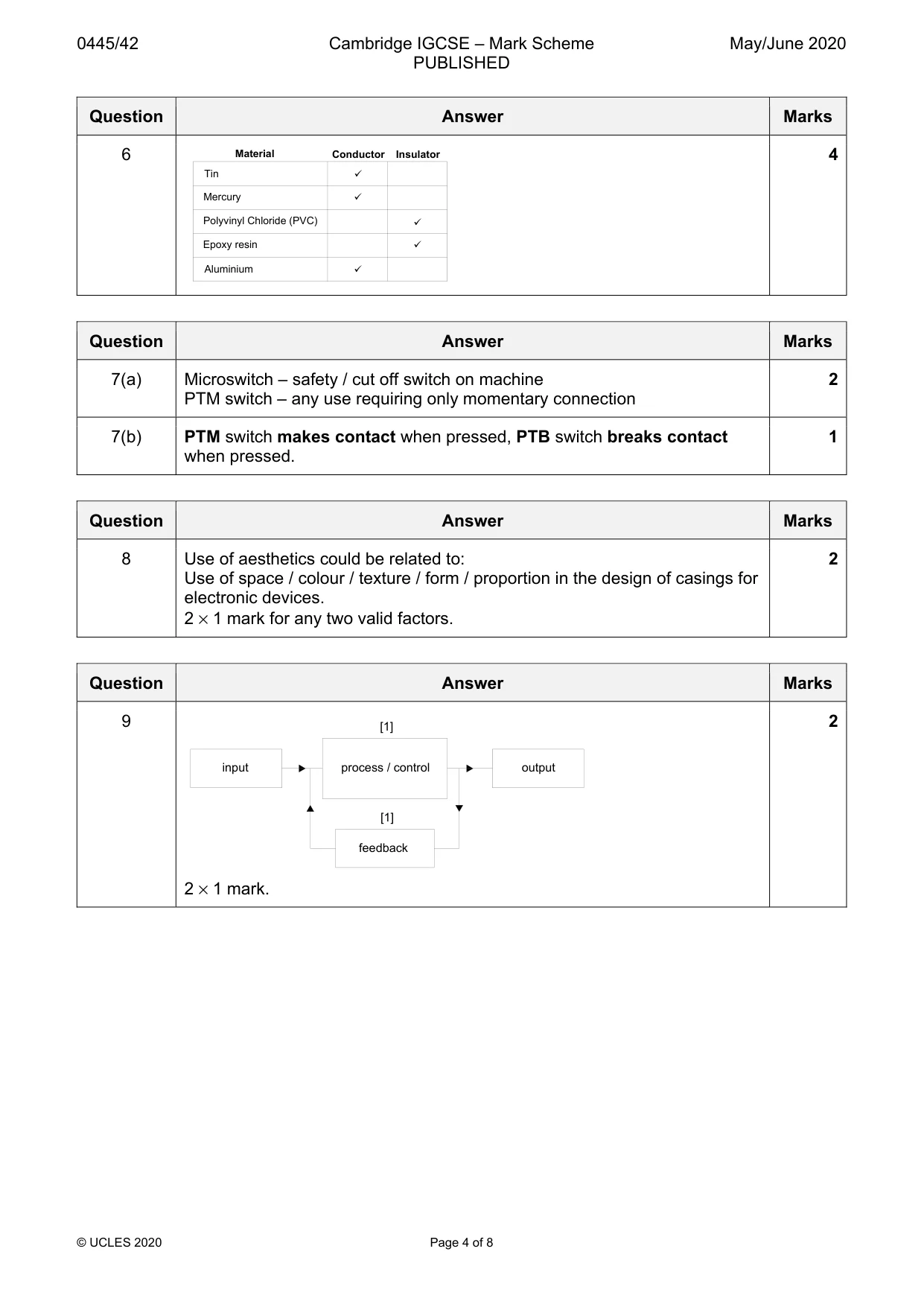
Mark scheme: 6 Material Conductor Insulator 4 Tin Mercury Polyvinyl Chloride (PVC) Epoxy resin Aluminium
Question 7
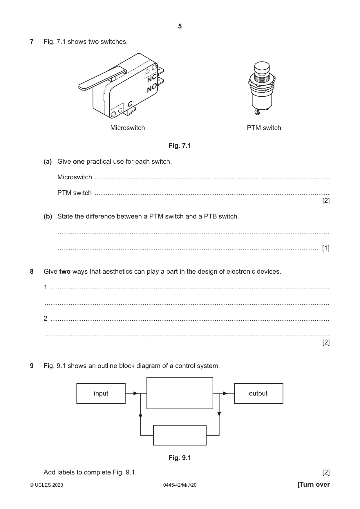
7 Fig. 7.1 shows two switches. Microswitch PTM switch Fig. 7.1 (a) Give one practical use for each switch. Microswitch ............................................................................................................................... PTM switch ............................................................................................................................... [2] (b) State the difference between a PTM switch and a PTB switch. ................................................................................................................................................... ............................................................................................................................................. [1]
Mark scheme: 7(a) Microswitch – safety / cut off switch on machine 2 PTM switch – any use requiring only momentary connection 7(b) PTM switch makes contact when pressed, PTB switch breaks contact 1 when pressed.
Q8 · Give two ways that aesthetics can play a part in the design of electronic devices
8 Give two ways that aesthetics can play a part in the design of electronic devices. 1 ....................................................................................................................................................... .......................................................................................................................................................... 2 ....................................................................................................................................................... .......................................................................................................................................................... [2]
Mark scheme: 8 Use of aesthetics could be related to: 2 Use of space / colour / texture / form / proportion in the design of casings for electronic devices. 2 × 1 mark for any two valid factors.
Q9 · An outline block diagram of a control system
9 Fig. 9.1 shows an outline block diagram of a control system. input output Fig. 9.1 Add labels to complete Fig. 9.1. [2]
Mark scheme: 9 [1] 2 input process / control output [1] feedback 2 × 1 mark. Section B
Q10 · Beams made from a single piece of wood are limited in length to the size of the tree that…
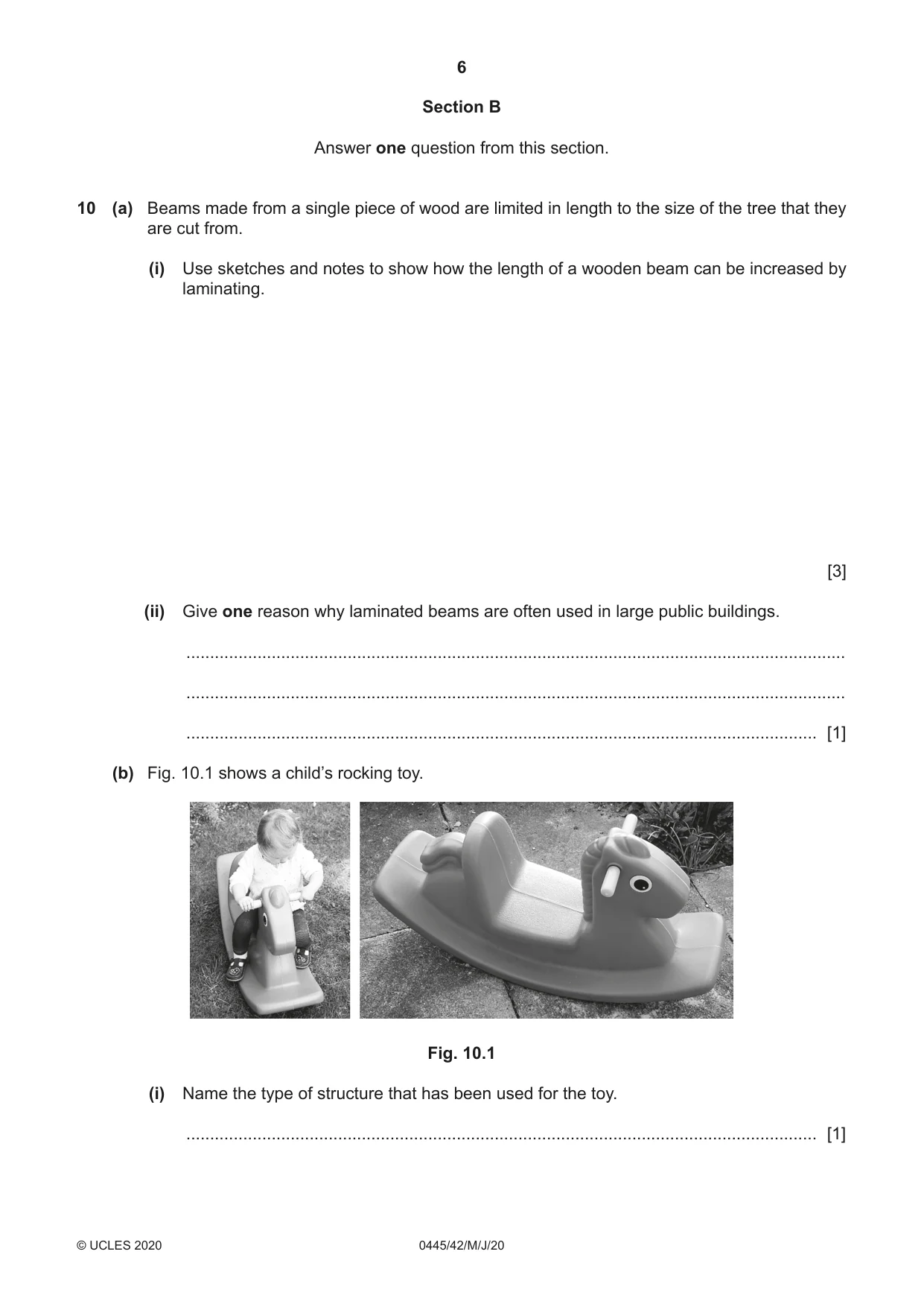
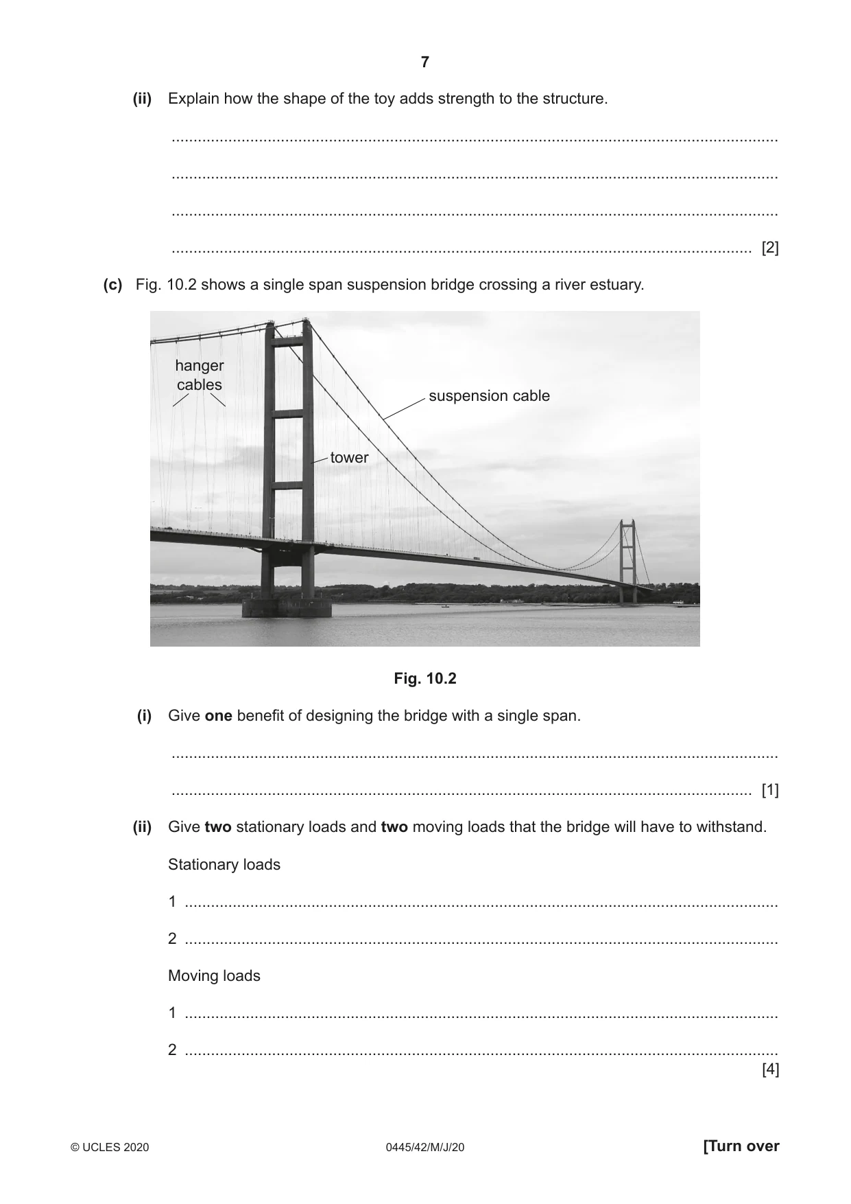
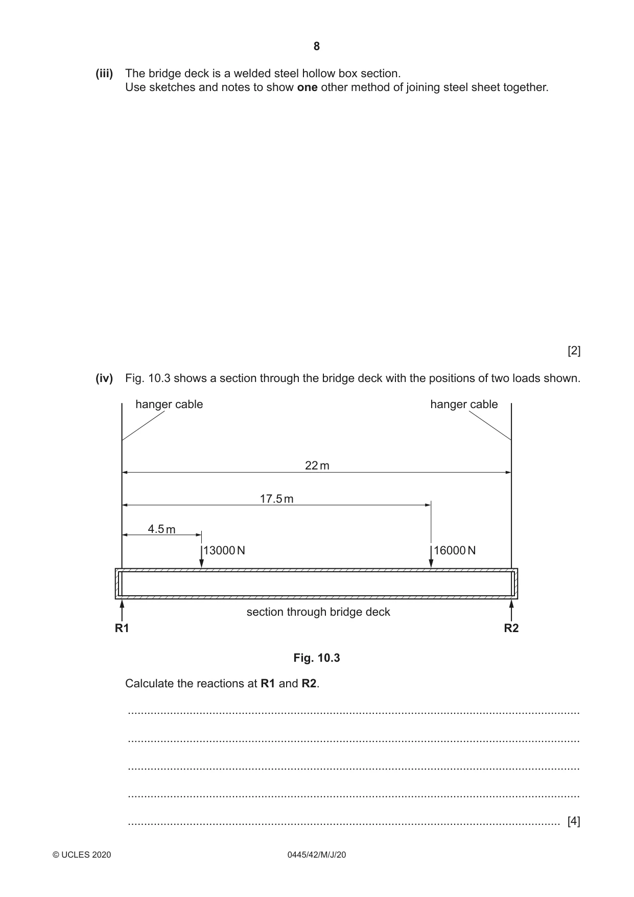
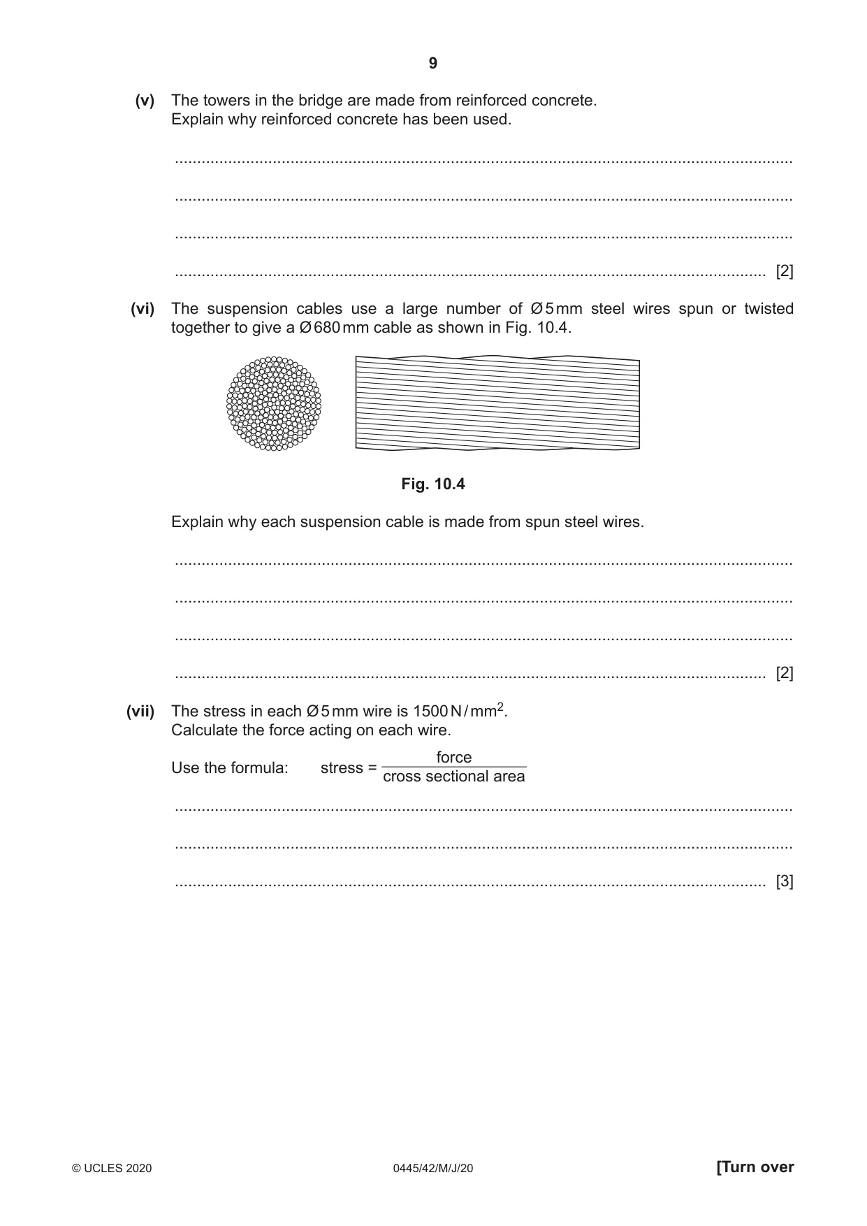
10 (a) Beams made from a single piece of wood are limited in length to the size of the tree that they are cut from. (i) Use sketches and notes to show how the length of a wooden beam can be increased by laminating. [3] (ii) Give one reason why laminated beams are often used in large public buildings. ........................................................................................................................................... ........................................................................................................................................... ..................................................................................................................................... [1] (b) Fig. 10.1 shows a child’s rocking toy. Fig. 10.1 (i) Name the type of structure that has been used for the toy. ..................................................................................................................................... [1] (ii) Explain how the shape of the toy adds strength to the structure. ........................................................................................................................................... ........................................................................................................................................... ........................................................................................................................................... ..................................................................................................................................... [2] (c) Fig. 10.2 shows a single span suspension bridge crossing a river estuary. hanger cables suspension cable tower Fig. 10.2 (i) Give one benefit of designing the bridge with a single span. ........................................................................................................................................... ..................................................................................................................................... [1] (ii) Give two stationary loads and two moving loads that the bridge will have to withstand. Stationary loads 1 ........................................................................................................................................ 2 ........................................................................................................................................ Moving loads 1 ........................................................................................................................................ 2 ........................................................................................................................................ [4] (iii) The bridge deck is a welded steel hollow box section. Use sketches and notes to show one other method of joining steel sheet together. [2] (iv) Fig. 10.3 shows a section through the bridge deck with the positions of two loads shown. hanger cable hanger cable 22 m 17.5 m 4.5 m 13000 N 16000 N section through bridge deck R1 R2 Fig. 10.3 Calculate the reactions at R1 and R2. ........................................................................................................................................... ........................................................................................................................................... ........................................................................................................................................... ........................................................................................................................................... ..................................................................................................................................... [4] (v) The towers in the bridge are made from reinforced concrete. Explain why reinforced concrete has been used. ........................................................................................................................................... ........................................................................................................................................... ........................................................................................................................................... ..................................................................................................................................... [2] (vi) The suspension cables use a large number of Ø 5 mm steel wires spun or twisted together to give a Ø 680 mm cable as shown in Fig. 10.4. Fig. 10.4 Explain why each suspension cable is made from spun steel wires. ........................................................................................................................................... ........................................................................................................................................... ........................................................................................................................................... ..................................................................................................................................... [2] (vii) The stress in each Ø 5 mm wire is 1500 N / mm2. Calculate the force acting on each wire. force Use the formula: stress = cross sectional area ........................................................................................................................................... ........................................................................................................................................... ..................................................................................................................................... [3]
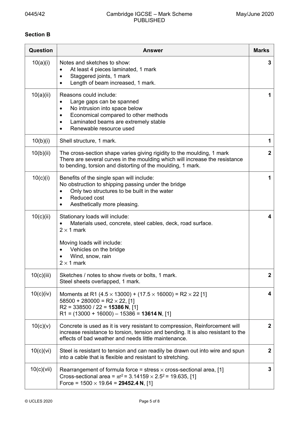
Mark scheme: 10(a)(i) Notes and sketches to show: 3 • At least 4 pieces laminated, 1 mark • Staggered joints, 1 mark • Length of beam increased, 1 mark. 10(a)(ii) Reasons could include: 1 • Large gaps can be spanned • No intrusion into space below • Economical compared to other methods • Laminated beams are extremely stable • Renewable resource used 10(b)(i) Shell structure, 1 mark. 1 10(b)(ii) The cross-section shape varies giving rigidity to the moulding, 1 mark 2 There are several curves in the moulding which will increase the resistance to bending, torsion and distorting of the moulding, 1 mark. 10(c)(i) Benefits of the single span will include: 1 No obstruction to shipping passing under the bridge • Only two structures to be built in the water • Reduced cost • Aesthetically more pleasing. 10(c)(ii) Stationary loads will include: 4 • Materials used, concrete, steel cables, deck, road surface. 2 × 1 mark Moving loads will include: • Vehicles on the bridge • Wind, snow, rain 2 × 1 mark 10(c)(iii) Sketches / notes to show rivets or bolts, 1 mark. 2 Steel sheets overlapped, 1 mark. 10(c)(iv) Moments at R1 (4.5 × 13000) + (17.5 × 16000) = R2 × 22 [1] 4 58500 + 280000 = R2 × 22, [1] R2 = 338500 / 22 = 15386 N, [1] R1 = (13000 + 16000) – 15386 = 13614 N, [1] 10(c)(v) Concrete is used as it is very resistant to compression, Reinforcement will 2 increase resistance to torsion, tension and bending. It is also resistant to the effects of bad weather and needs little maintenance. 10(c)(vi) Steel is resistant to tension and can readily be drawn out into wire and spun 2 into a cable that is flexible and resistant to stretching. 10(c)(vii) Rearrangement of formula force = stress × cross-sectional area, [1] 3 Cross-sectional area = πr2 = 3.14159 × 2.52 = 19.635, [1] Force = 1500 × 19.64 = 29452.4 N, [1]
Q11 · Two uses for bevel gears
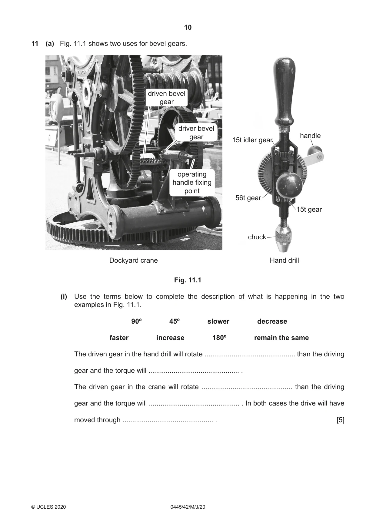
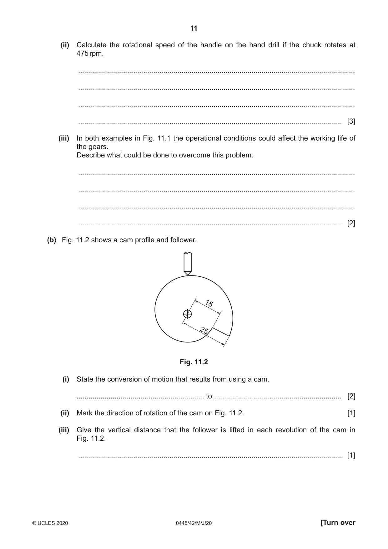
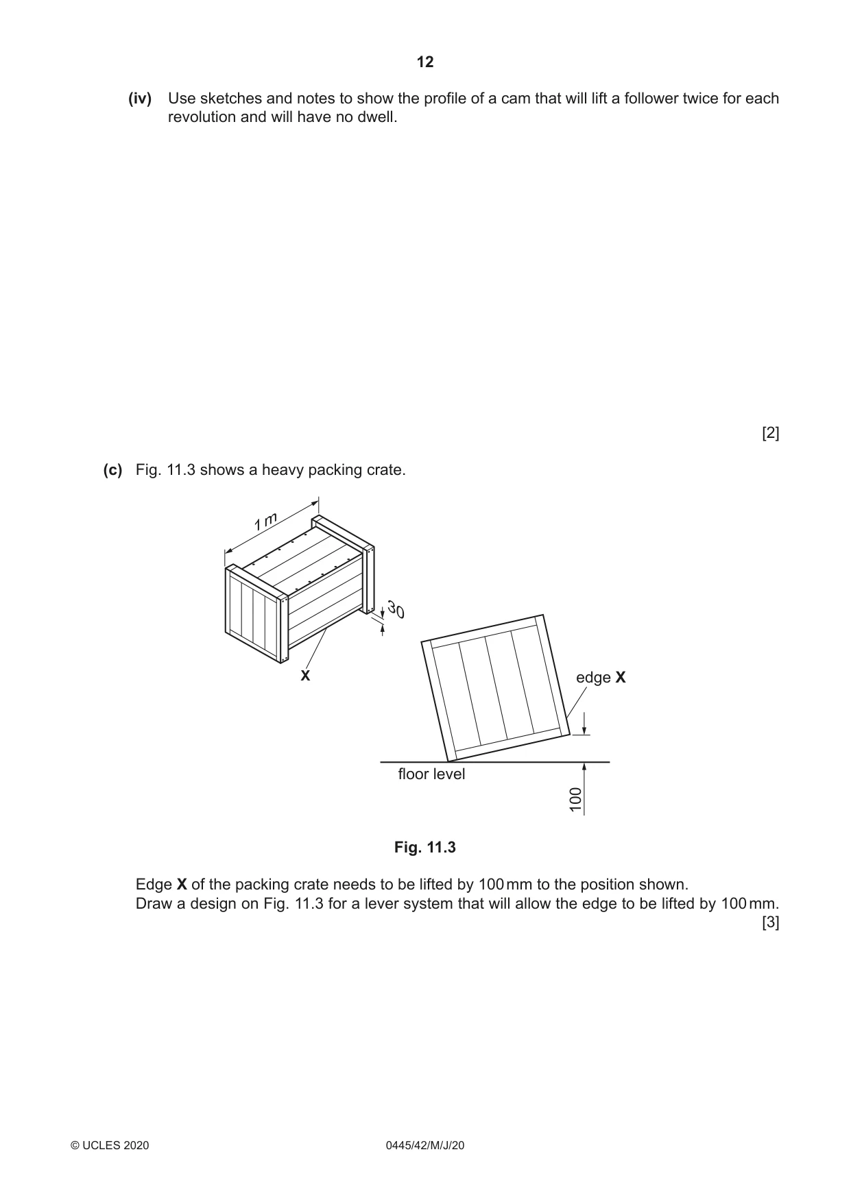
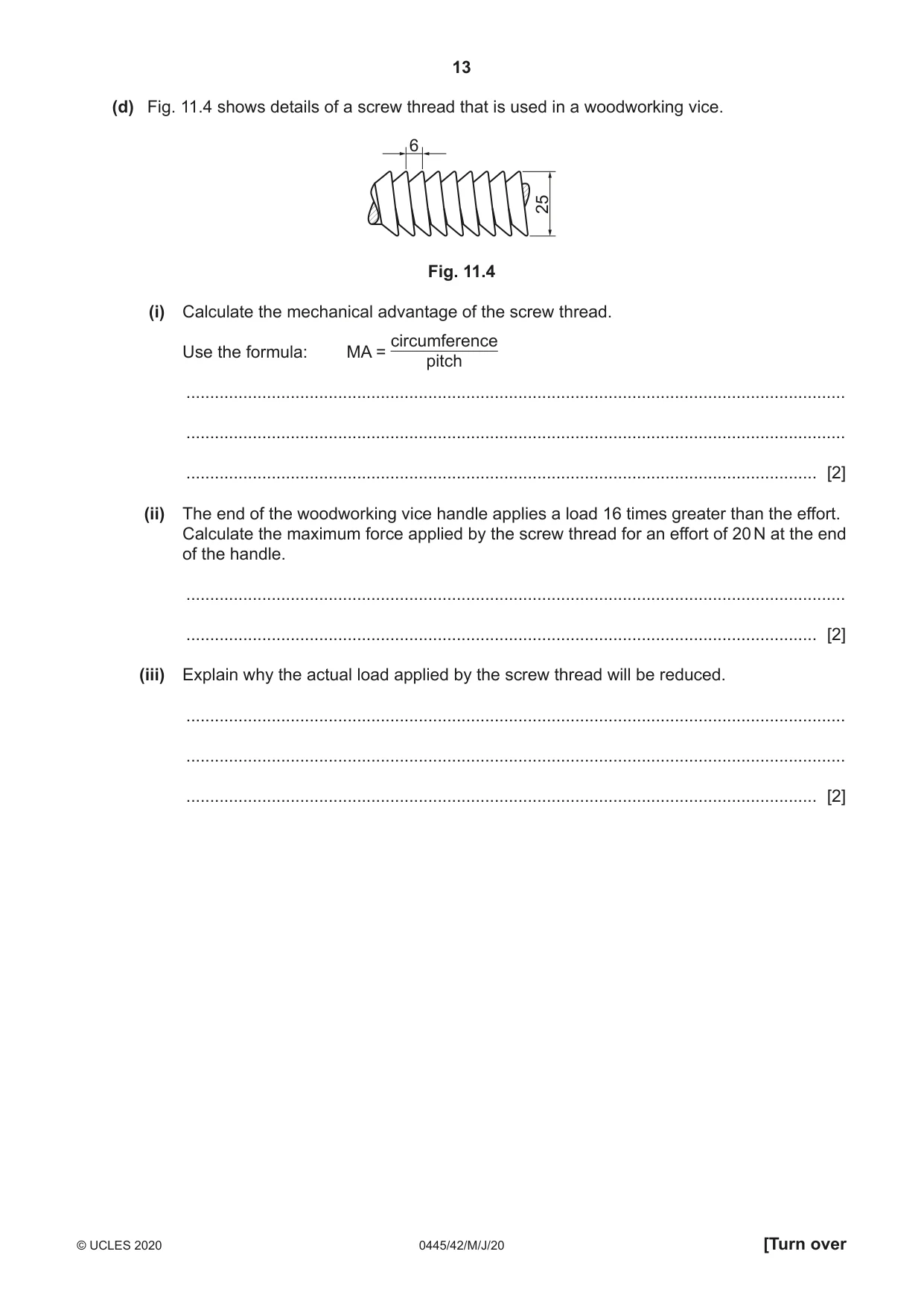
11 (a) Fig. 11.1 shows two uses for bevel gears. driven bevel gear driver bevel gear handle 15t idler gear operating handle fixing point 56t gear 15t gear chuck Dockyard crane Hand drill Fig. 11.1 (i) Use the terms below to complete the description of what is happening in the two examples in Fig. 11.1. 90º 45º slower decrease faster increase 180º remain the same The driven gear in the hand drill will rotate ............................................... than the driving gear and the torque will ............................................... . The driven gear in the crane will rotate ............................................... than the driving gear and the torque will ............................................... . In both cases the drive will have moved through ............................................... . [5] (ii) Calculate the rotational speed of the handle on the hand drill if the chuck rotates at 475 rpm. ........................................................................................................................................... ........................................................................................................................................... ........................................................................................................................................... ..................................................................................................................................... [3] (iii) In both examples in Fig. 11.1 the operational conditions could affect the working life of the gears. Describe what could be done to overcome this problem. ........................................................................................................................................... ........................................................................................................................................... ........................................................................................................................................... ..................................................................................................................................... [2] (b) Fig. 11.2 shows a cam profile and follower. 15 25 Fig. 11.2 (i) State the conversion of motion that results from using a cam. ................................................................ to ................................................................ [2] (ii) Mark the direction of rotation of the cam on Fig. 11.2. [1] (iii) Give the vertical distance that the follower is lifted in each revolution of the cam in Fig. 11.2. ..................................................................................................................................... [1] (iv) Use sketches and notes to show the profile of a cam that will lift a follower twice for each revolution and will have no dwell. [2] (c) Fig. 11.3 shows a heavy packing crate. X edge X floor level 100 Fig. 11.3 Edge X of the packing crate needs to be lifted by 100 mm to the position shown. Draw a design on Fig. 11.3 for a lever system that will allow the edge to be lifted by 100 mm. [3] (d) Fig. 11.4 shows details of a screw thread that is used in a woodworking vice. 6 25 Fig. 11.4 (i) Calculate the mechanical advantage of the screw thread. circumference Use the formula: MA = pitch ........................................................................................................................................... ........................................................................................................................................... ..................................................................................................................................... [2] (ii) The end of the woodworking vice handle applies a load 16 times greater than the effort. Calculate the maximum force applied by the screw thread for an effort of 20 N at the end of the handle. ........................................................................................................................................... ..................................................................................................................................... [2] (iii) Explain why the actual load applied by the screw thread will be reduced. ........................................................................................................................................... ........................................................................................................................................... ..................................................................................................................................... [2]
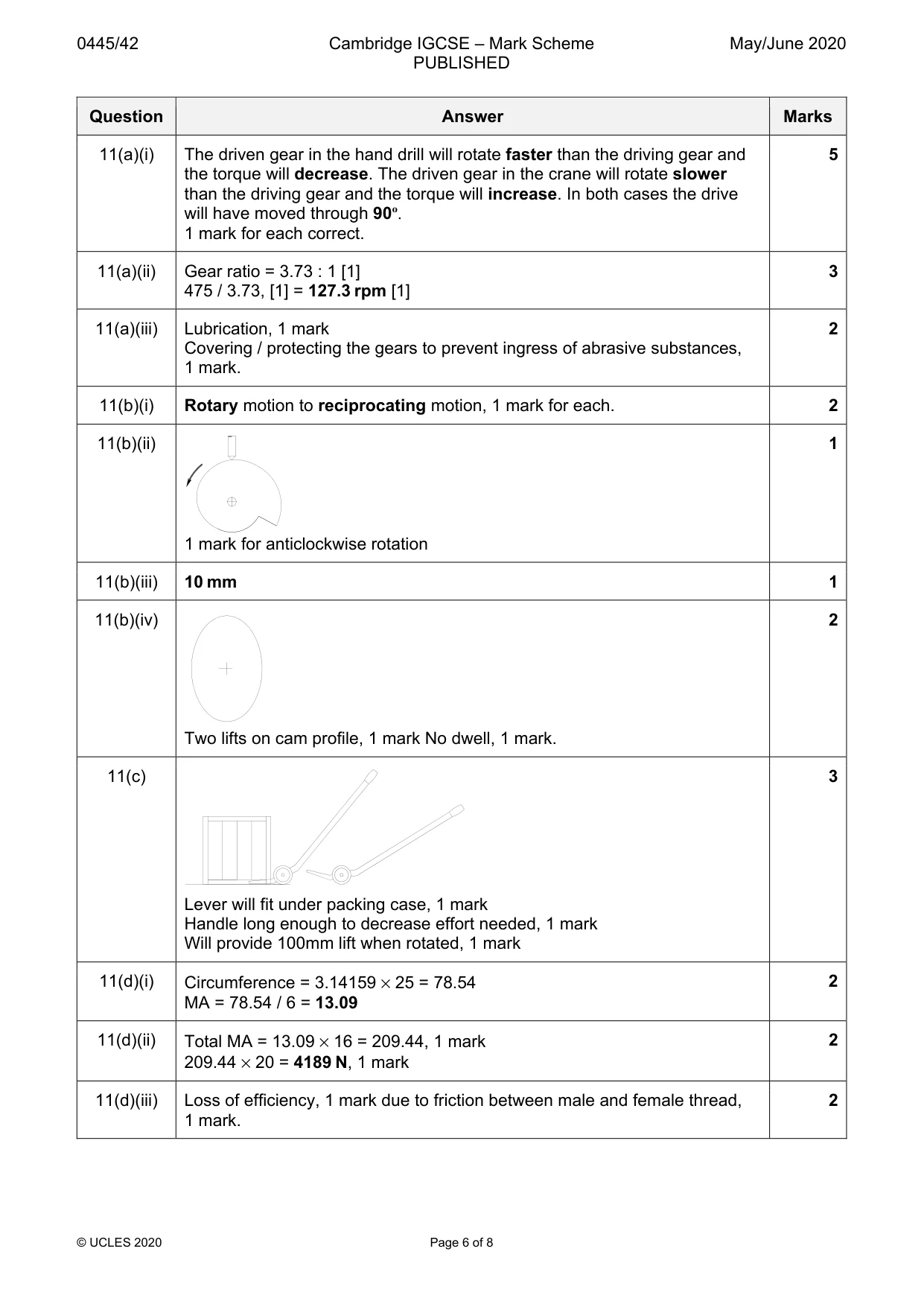
Mark scheme: 11(a)(i) The driven gear in the hand drill will rotate faster than the driving gear and 5 the torque will decrease. The driven gear in the crane will rotate slower than the driving gear and the torque will increase. In both cases the drive will have moved through 90º. 1 mark for each correct. 11(a)(ii) Gear ratio = 3.73 : 1 [1] 3 475 / 3.73, [1] = 127.3 rpm [1] 11(a)(iii) Lubrication, 1 mark 2 Covering / protecting the gears to prevent ingress of abrasive substances, 1 mark. 11(b)(i) Rotary motion to reciprocating motion, 1 mark for each. 2 11(b)(ii) 1 1 mark for anticlockwise rotation 11(b)(iii) 10 mm 1 11(b)(iv) 2 Two lifts on cam profile, 1 mark No dwell, 1 mark. 11(c) 3 Lever will fit under packing case, 1 mark Handle long enough to decrease effort needed, 1 mark Will provide 100mm lift when rotated, 1 mark 11(d)(i) Circumference = 3.14159 × 25 = 78.54 2 MA = 78.54 / 6 = 13.09 11(d)(ii) Total MA = 13.09 × 16 = 209.44, 1 mark 2 209.44 × 20 = 4189 N, 1 mark 11(d)(iii) Loss of efficiency, 1 mark due to friction between male and female thread, 2 1 mark.
Q12 · Part of the circuit for an LED night light
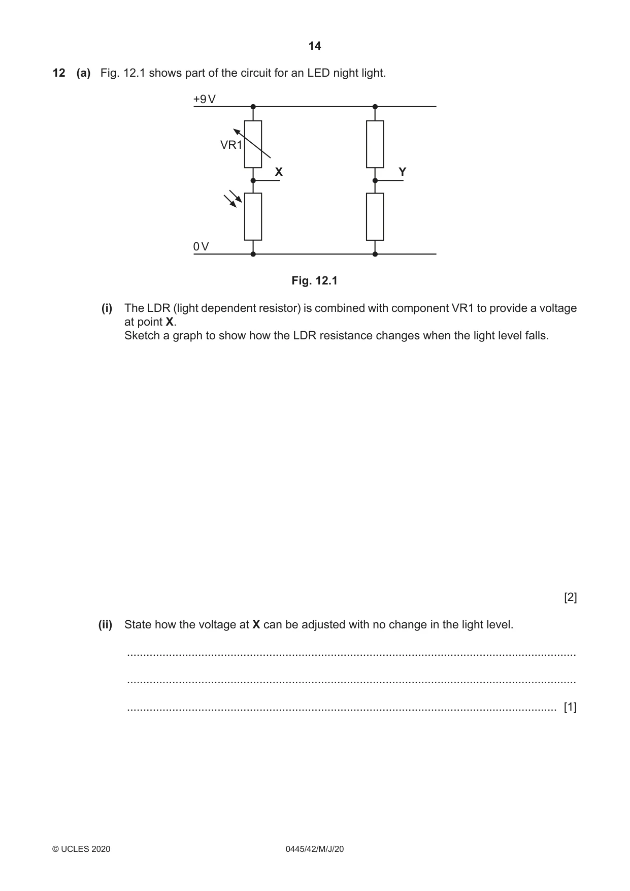
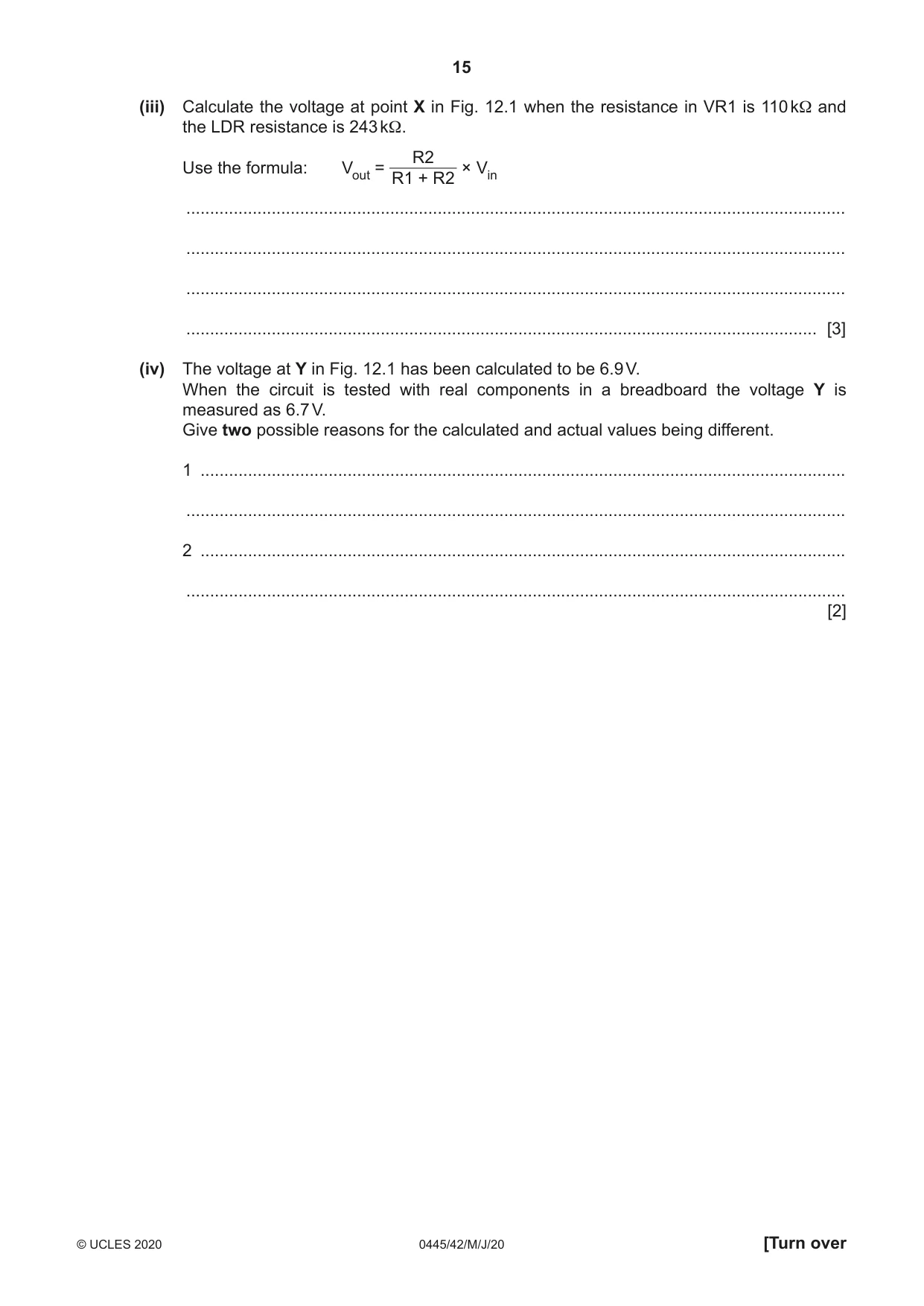
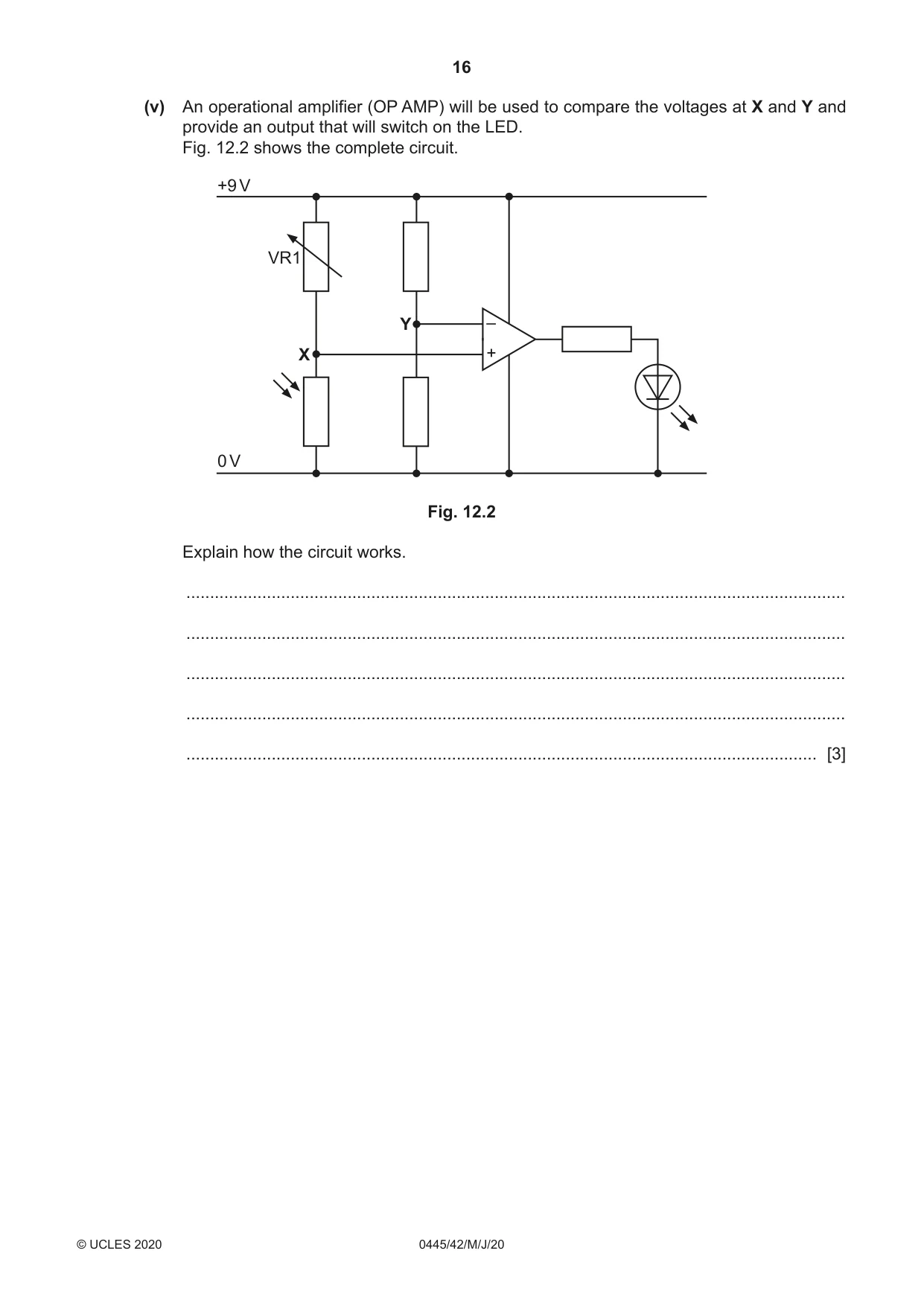
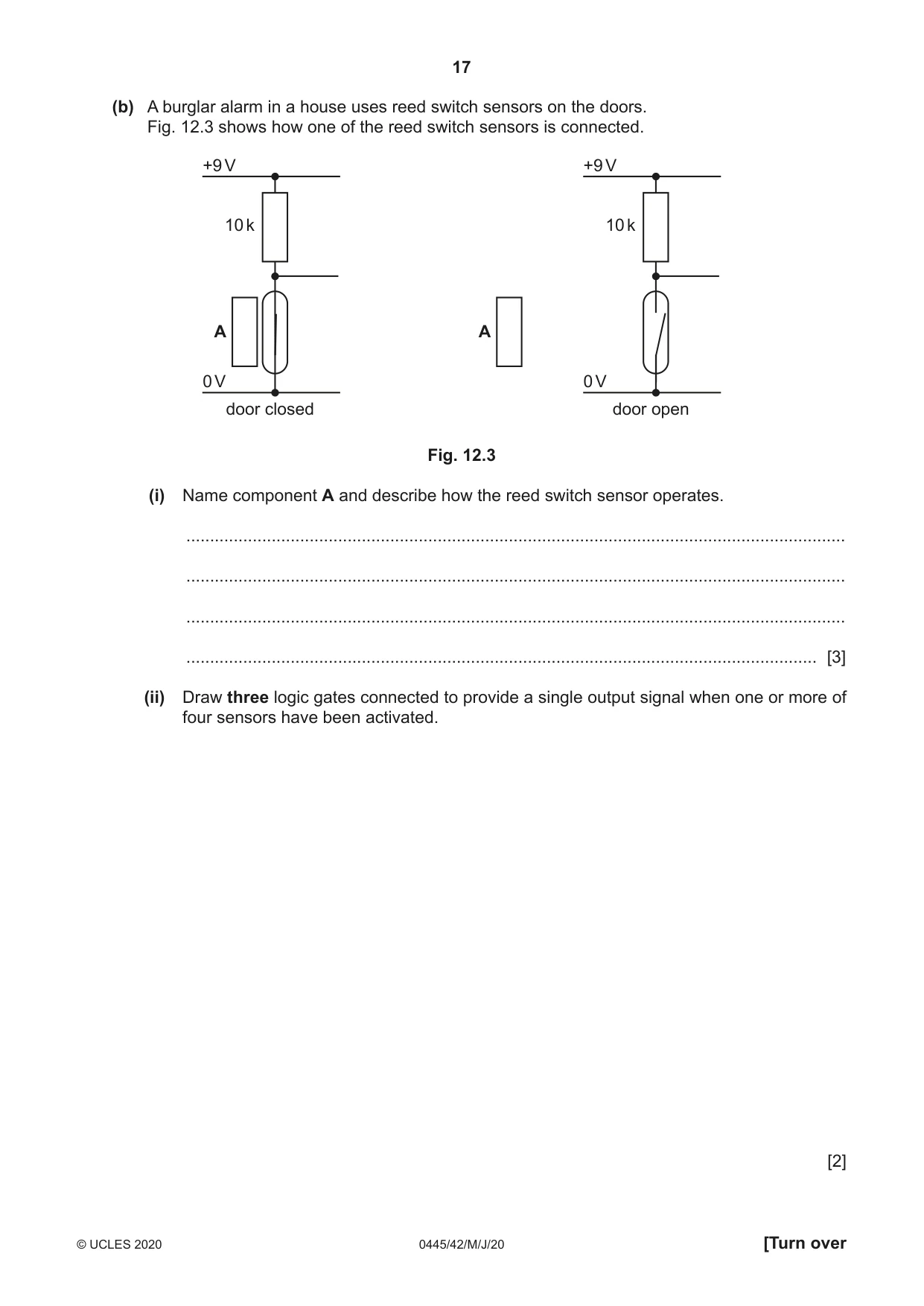
12 (a) Fig. 12.1 shows part of the circuit for an LED night light. +9 V VR1 X Y 0 V Fig. 12.1 (i) The LDR (light dependent resistor) is combined with component VR1 to provide a voltage at point X. Sketch a graph to show how the LDR resistance changes when the light level falls. [2] (ii) State how the voltage at X can be adjusted with no change in the light level. ........................................................................................................................................... ........................................................................................................................................... ..................................................................................................................................... [1] (iii) Calculate the voltage at point X in Fig. 12.1 when the resistance in VR1 is 110 kΩ and the LDR resistance is 243 kΩ. R2 Use the formula: Vout = × Vin R1 + R2 ........................................................................................................................................... ........................................................................................................................................... ........................................................................................................................................... ..................................................................................................................................... [3] (iv) The voltage at Y in Fig. 12.1 has been calculated to be 6.9 V. When the circuit is tested with real components in a breadboard the voltage Y is measured as 6.7 V. Give two possible reasons for the calculated and actual values being different. 1 ........................................................................................................................................ ........................................................................................................................................... 2 ........................................................................................................................................ ........................................................................................................................................... [2] (v) An operational amplifier (OP AMP) will be used to compare the voltages at X and Y and provide an output that will switch on the LED. Fig. 12.2 shows the complete circuit. +9 V VR1 Y – X + 0 V Fig. 12.2 Explain how the circuit works. ........................................................................................................................................... ........................................................................................................................................... ........................................................................................................................................... ........................................................................................................................................... ..................................................................................................................................... [3]
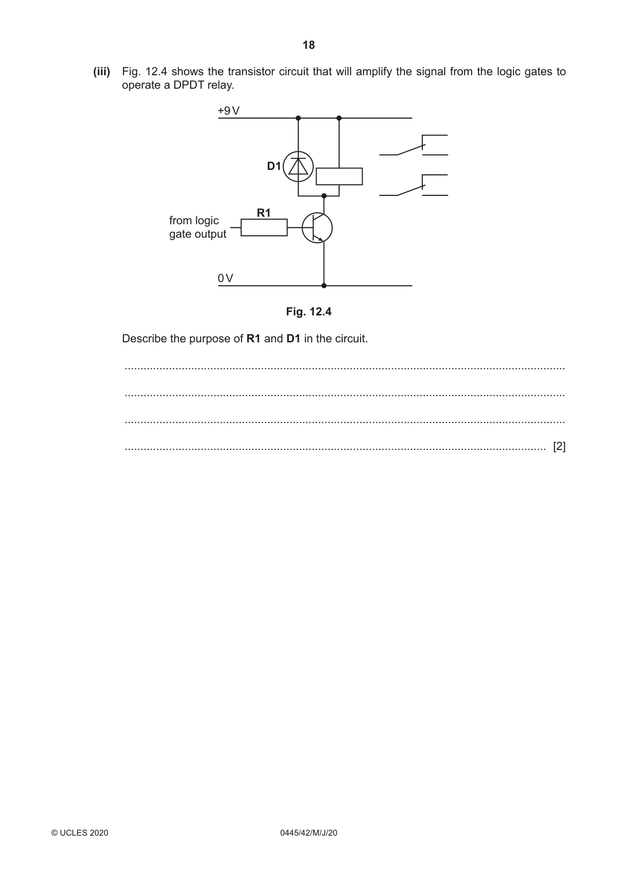
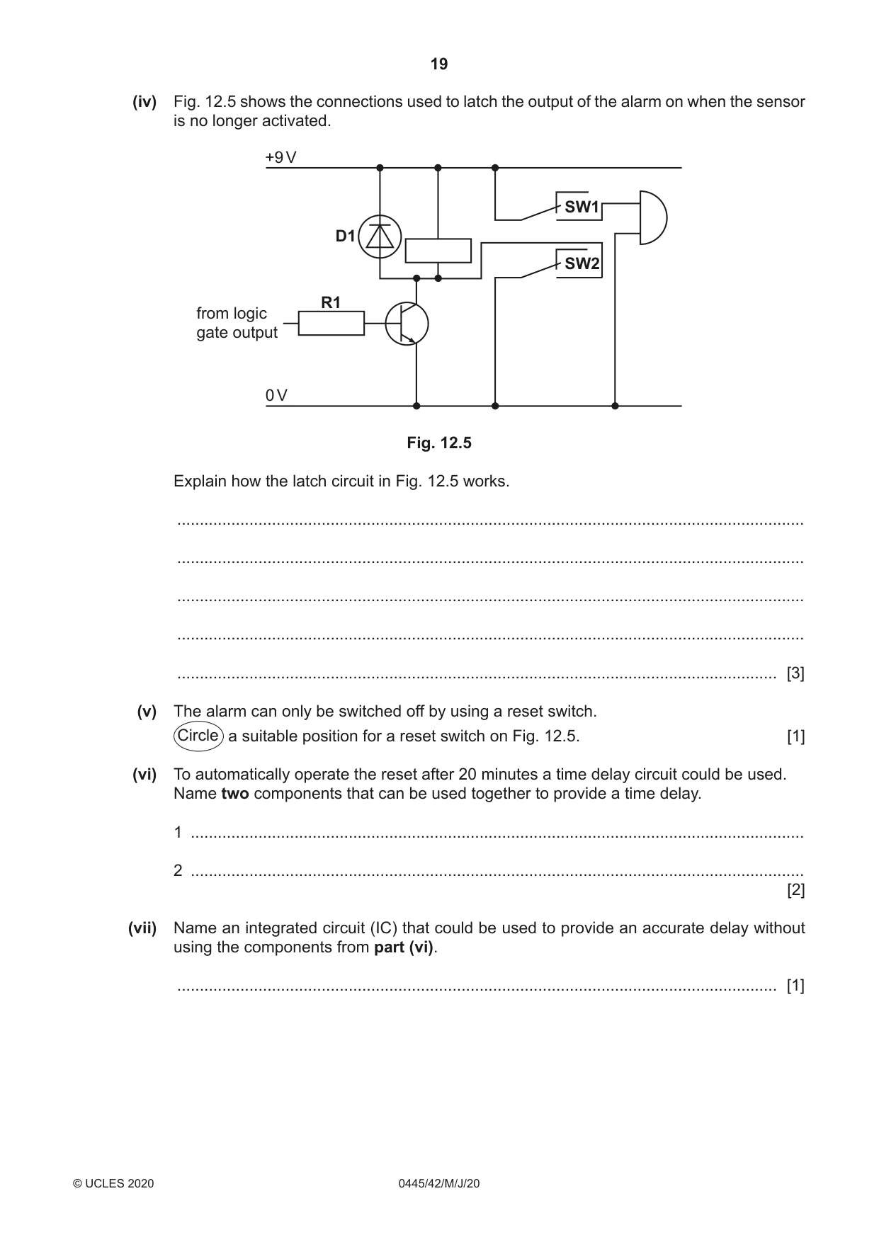
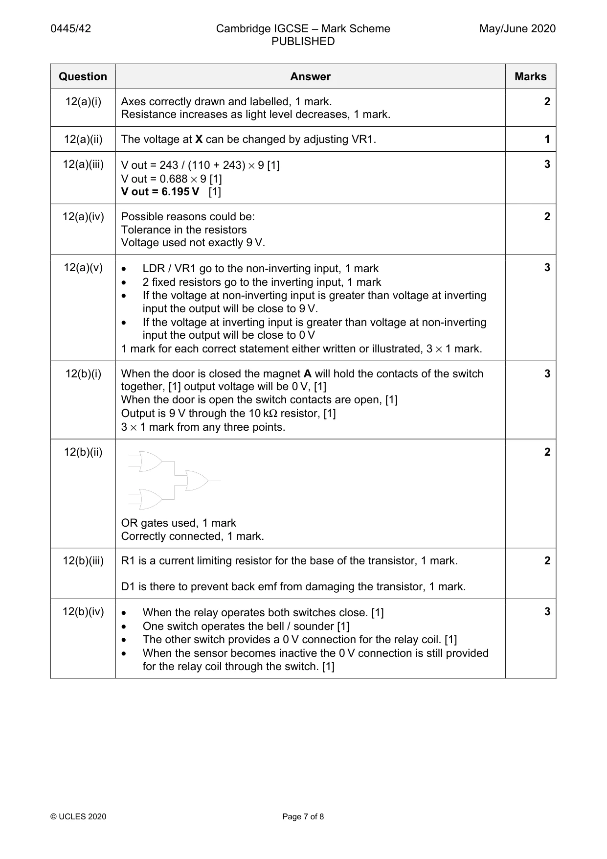
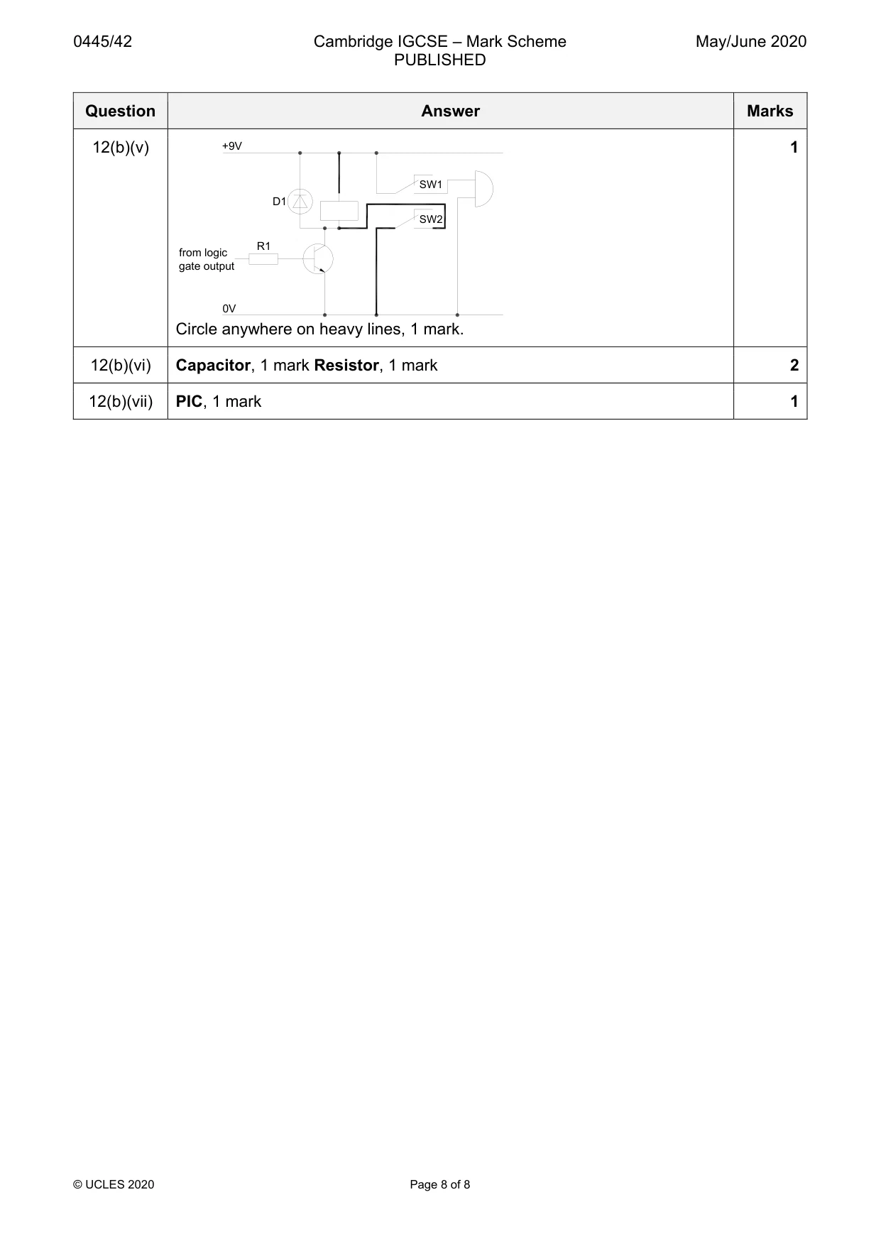
Mark scheme: 12(a)(i) Axes correctly drawn and labelled, 1 mark. 2 Resistance increases as light level decreases, 1 mark. 12(a)(ii) The voltage at X can be changed by adjusting VR1. 1 12(a)(iii) V out = 243 / (110 + 243) × 9 [1] 3 V out = 0.688 × 9 [1] V out = 6.195 V [1] 12(a)(iv) Possible reasons could be: 2 Tolerance in the resistors Voltage used not exactly 9 V. 12(a)(v) • LDR / VR1 go to the non-inverting input, 1 mark 3 • 2 fixed resistors go to the inverting input, 1 mark • If the voltage at non-inverting input is greater than voltage at inverting input the output will be close to 9 V. • If the voltage at inverting input is greater than voltage at non-inverting input the output will be close to 0 V 1 mark for each correct statement either written or illustrated, 3 × 1 mark. 12(b)(i) When the door is closed the magnet A will hold the contacts of the switch 3 together, [1] output voltage will be 0 V, [1] When the door is open the switch contacts are open, [1] Output is 9 V through the 10 kΩ resistor, [1] 3 × 1 mark from any three points. 12(b)(ii) 2 OR gates used, 1 mark Correctly connected, 1 mark. 12(b)(iii) R1 is a current limiting resistor for the base of the transistor, 1 mark. 2 D1 is there to prevent back emf from damaging the transistor, 1 mark. 12(b)(iv) • When the relay operates both switches close. [1] 3 • One switch operates the bell / sounder [1] • The other switch provides a 0 V connection for the relay coil. [1] • When the sensor becomes inactive the 0 V connection is still provided for the relay coil through the switch. [1] 12(b)(v) +9V 1 SW1 D1 SW2 R1 from logic gate output 0V Circle anywhere on heavy lines, 1 mark. 12(b)(vi) Capacitor, 1 mark Resistor, 1 mark 2 12(b)(vii) PIC, 1 mark 1
What was in this paper
The subtopics covered by these 12 questions, and how many questions each got. Open one in a new tab to see every Cambridge question on it.