Cambridge IGCSE Design and Technology 0445 — 2020 May/June Paper 4 · Variant 1
0445/41/M/J/20 · 12 questions · 91 marks · ≈102 min
The question paper and its mark scheme, free to read here and free to download. This is Cambridge’s own paper, exactly as it was sat.
Question paper20 pages
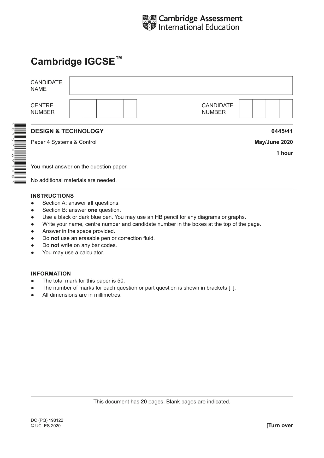

Mark scheme8 pages
Answers below. Sit the paper first if you are practising.
Questions as text
Q1 · The plastic casings of electric tools often include symbols on them
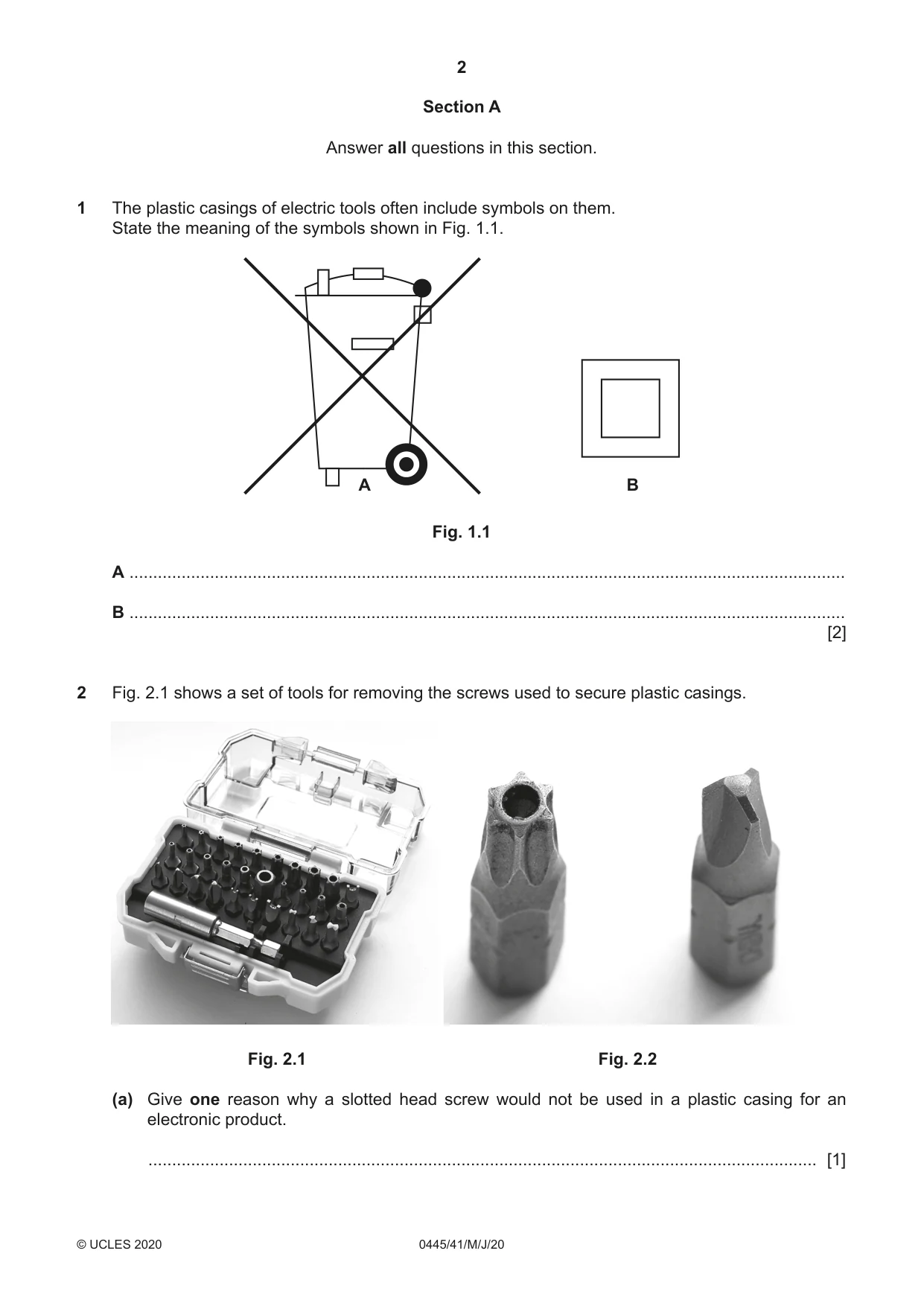
1 The plastic casings of electric tools often include symbols on them. State the meaning of the symbols shown in Fig. 1.1. A B Fig. 1.1 A ....................................................................................................................................................... B ....................................................................................................................................................... [2]
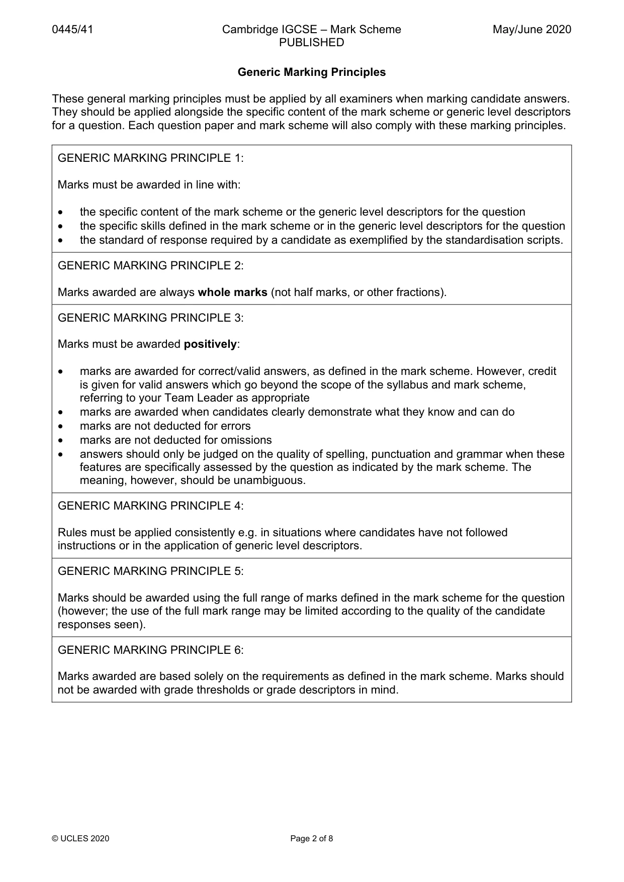
Mark scheme: Question Answer Marks 1 A – Do not place electrical item in general waste. 2 B – Double insulated, no earth connection.
Q2 · A set of tools for removing the screws used to secure plastic casings
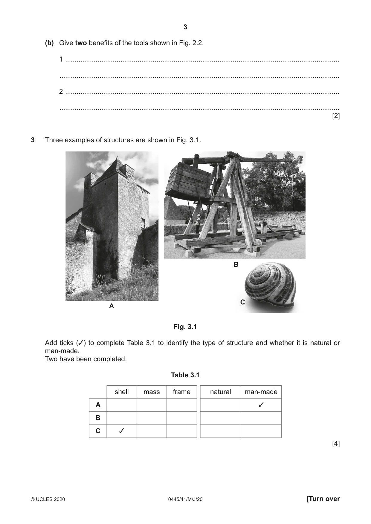
2 Fig. 2.1 shows a set of tools for removing the screws used to secure plastic casings. Fig. 2.1 Fig. 2.2 (a) Give one reason why a slotted head screw would not be used in a plastic casing for an electronic product. ............................................................................................................................................. [1] (b) Give two benefits of the tools shown in Fig. 2.2. 1 ................................................................................................................................................ ................................................................................................................................................... 2 ................................................................................................................................................ ................................................................................................................................................... [2]
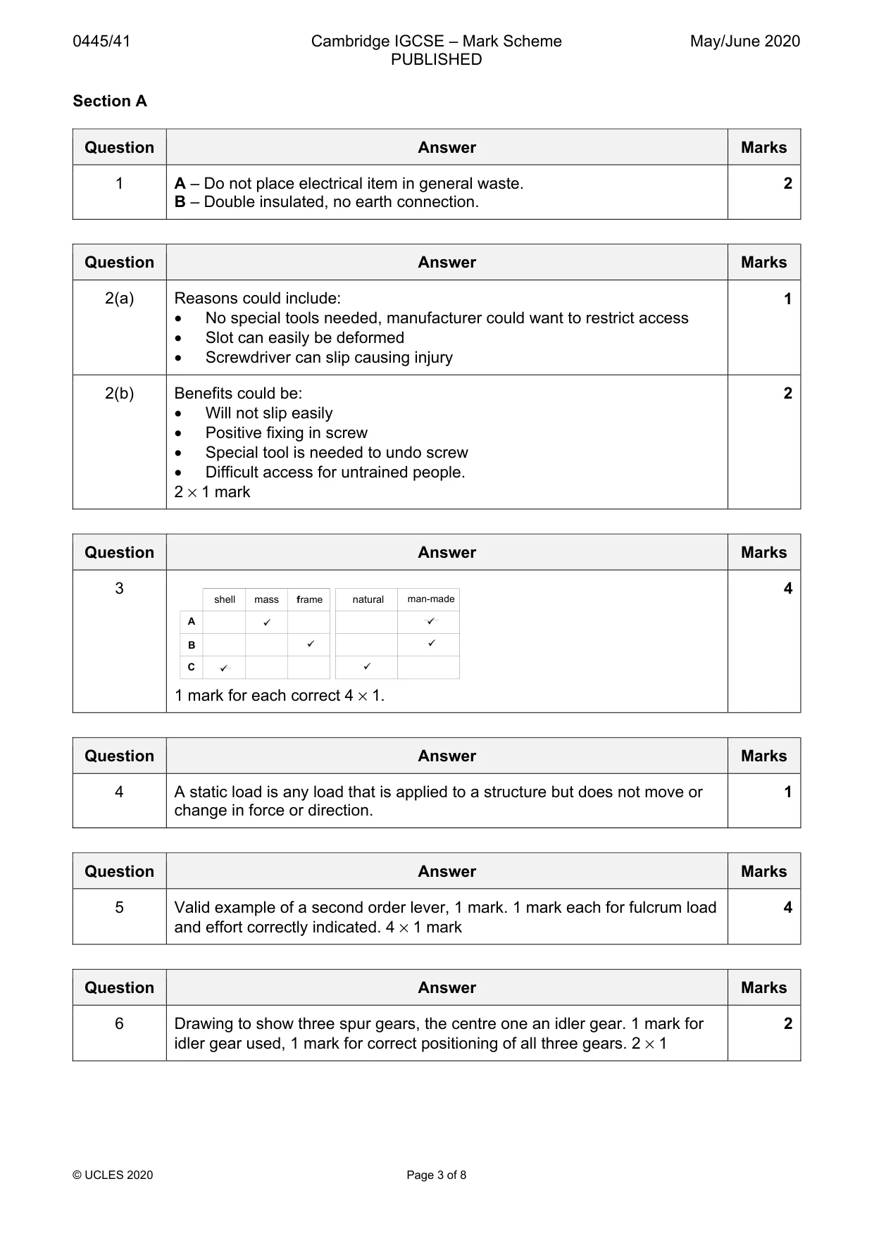
Mark scheme: 2(a) Reasons could include: 1 • No special tools needed, manufacturer could want to restrict access • Slot can easily be deformed • Screwdriver can slip causing injury 2(b) Benefits could be: 2 • Will not slip easily • Positive fixing in screw • Special tool is needed to undo screw • Difficult access for untrained people. 2 × 1 mark
Q3 · Three examples of structures are shown in Fig
3 Three examples of structures are shown in Fig. 3.1. B C A Fig. 3.1 Add ticks (✓) to complete Table 3.1 to identify the type of structure and whether it is natural or man-made. Two have been completed. Table 3.1 shell mass frame natural man-made A ✓ B C ✓ [4]
Mark scheme: 3 4 shell mass frame natural man-made A B C 1 mark for each correct 4 × 1.
Q4 · State the meaning of the term ‘static load’ in structural design
4 State the meaning of the term ‘static load’ in structural design. .................................................................................................................................................... [1]
Mark scheme: 4 A static load is any load that is applied to a structure but does not move or 1 change in force or direction.
Q5 · A spanner is an example of a second order lever
5 A spanner is an example of a second order lever. Draw a different example of a second order lever and show the position of the fulcrum, effort, and load. [4]
Mark scheme: 5 Valid example of a second order lever, 1 mark. 1 mark each for fulcrum load 4 and effort correctly indicated. 4 × 1 mark
Q6 · Spur gears can be used to transmit motion from one shaft to another
6 Spur gears can be used to transmit motion from one shaft to another. Draw an arrangement showing the minimum number of spur gears which will allow two shafts to rotate in the same direction. [2]
Mark scheme: 6 Drawing to show three spur gears, the centre one an idler gear. 1 mark for 2 idler gear used, 1 mark for correct positioning of all three gears. 2 × 1
Q7 · Two parts of a machine where movement takes place in the directions shown
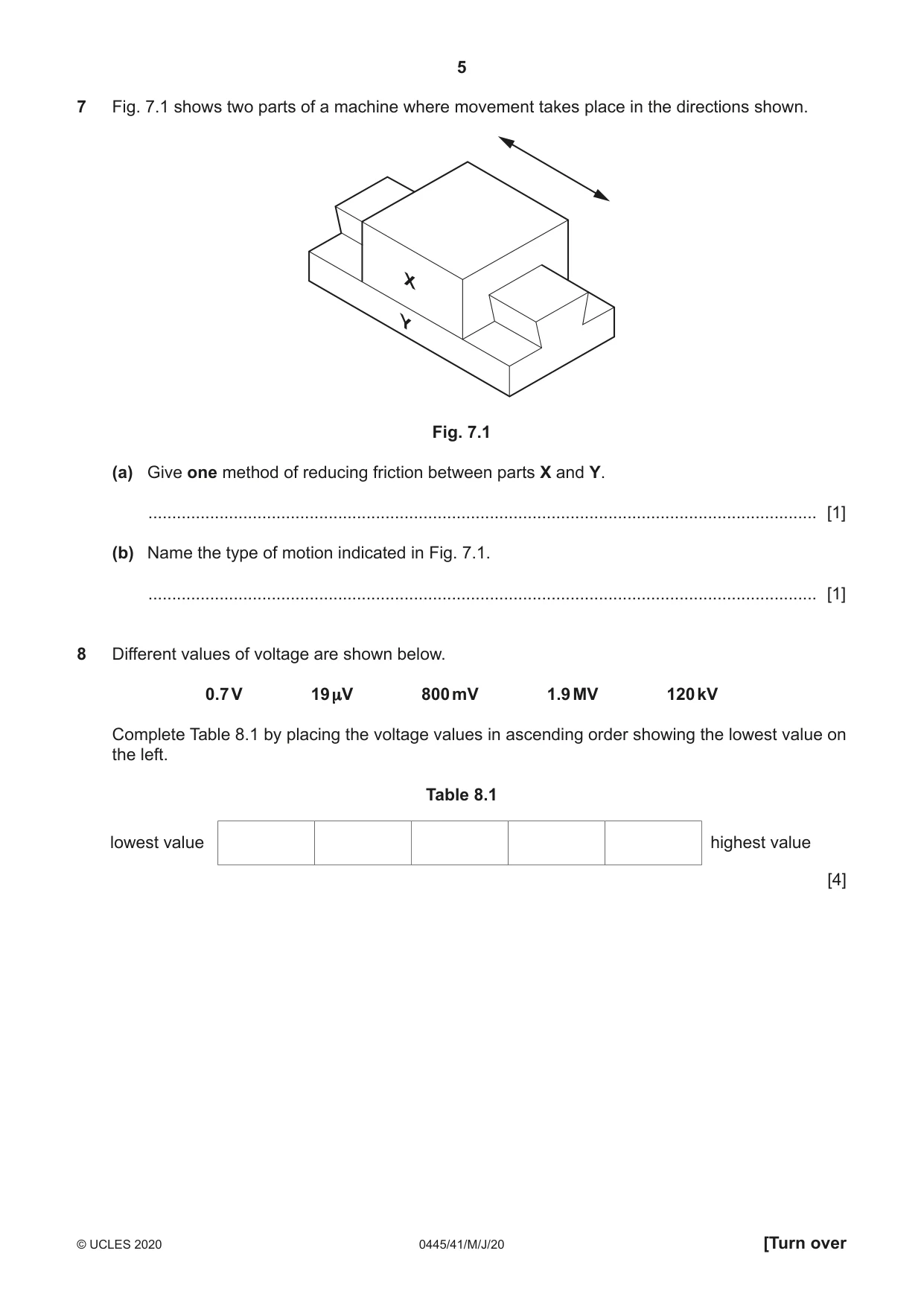
7 Fig. 7.1 shows two parts of a machine where movement takes place in the directions shown. Fig. 7.1 (a) Give one method of reducing friction between parts X and Y. ............................................................................................................................................. [1] (b) Name the type of motion indicated in Fig. 7.1. ............................................................................................................................................. [1]
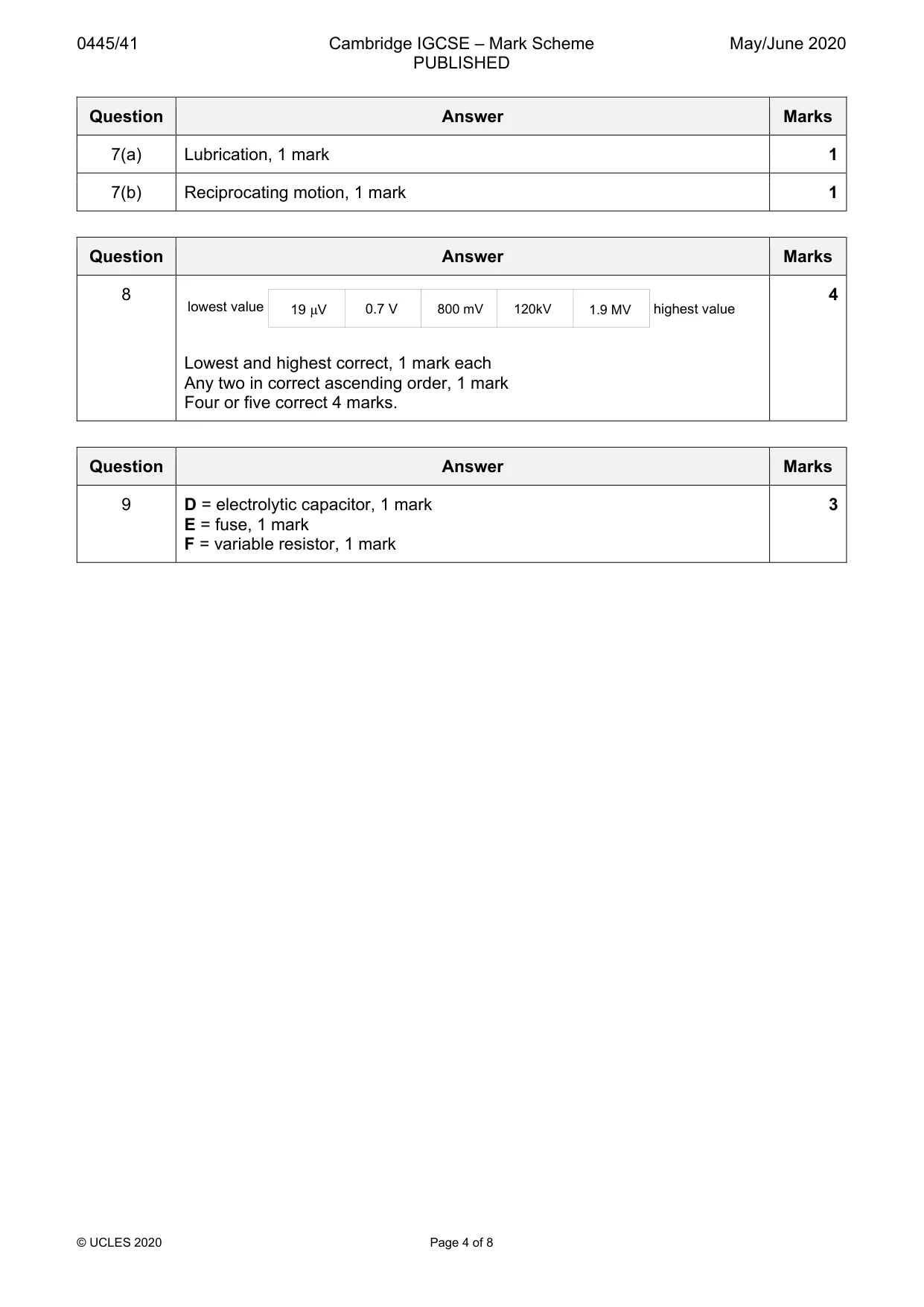
Mark scheme: 7(a) Lubrication, 1 mark 1 7(b) Reciprocating motion, 1 mark 1
Q8 · Different values of voltage are shown below
8 Different values of voltage are shown below. 0.7 V 19 μV 800 mV 1.9 MV 120 kV Complete Table 8.1 by placing the voltage values in ascending order showing the lowest value on the left. Table 8.1 lowest value highest value [4]
Mark scheme: 8 4 lowest value 19 µV 0.7 V 800 mV 120kV 1.9 MV highest value Lowest and highest correct, 1 mark each Any two in correct ascending order, 1 mark Four or five correct 4 marks.
Q9 · Three symbols used in electronic circuits
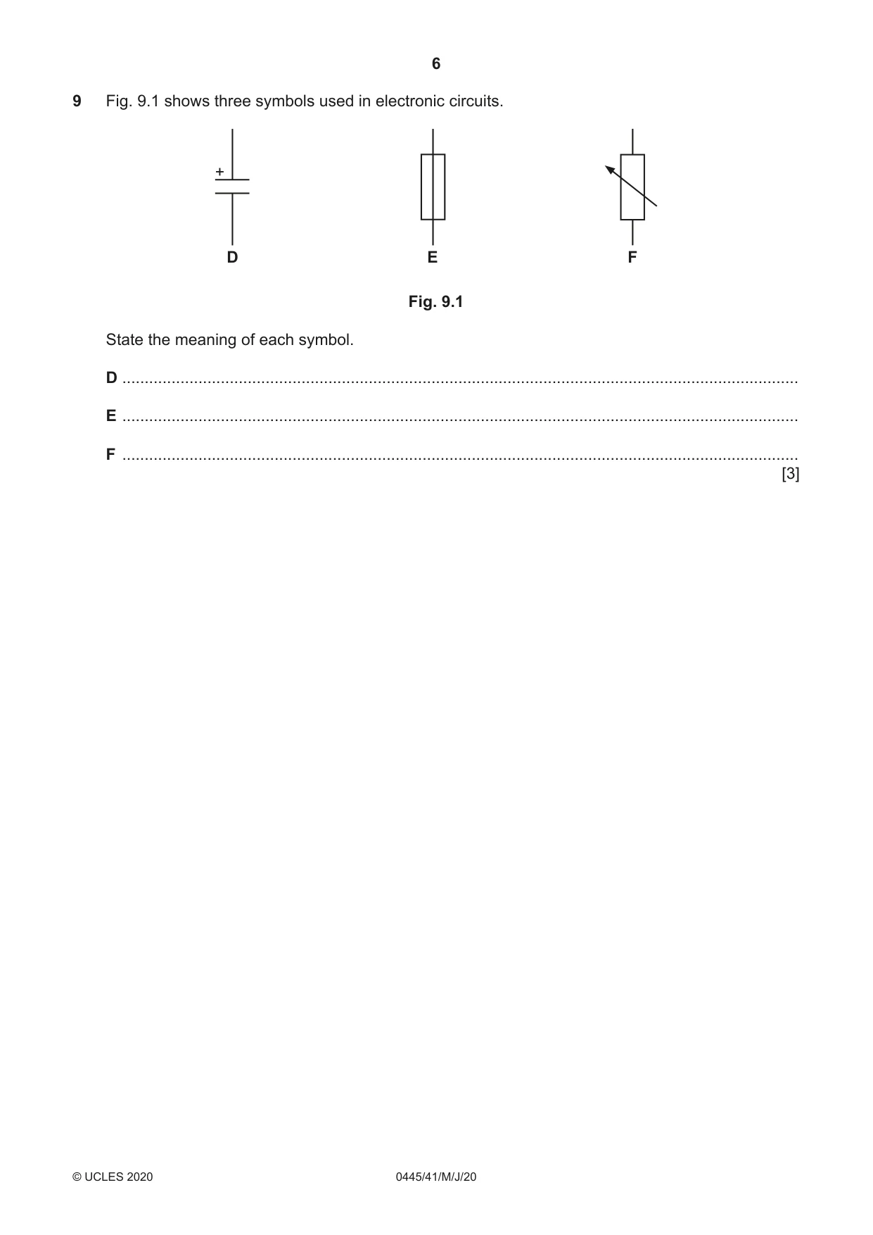
9 Fig. 9.1 shows three symbols used in electronic circuits. + D E F Fig. 9.1 State the meaning of each symbol. D ....................................................................................................................................................... E ....................................................................................................................................................... F ....................................................................................................................................................... [3]
Mark scheme: 9 D = electrolytic capacitor, 1 mark 3 E = fuse, 1 mark F = variable resistor, 1 mark Section B
Q10 · Describe what is meant by a ‘moment’ in a structure
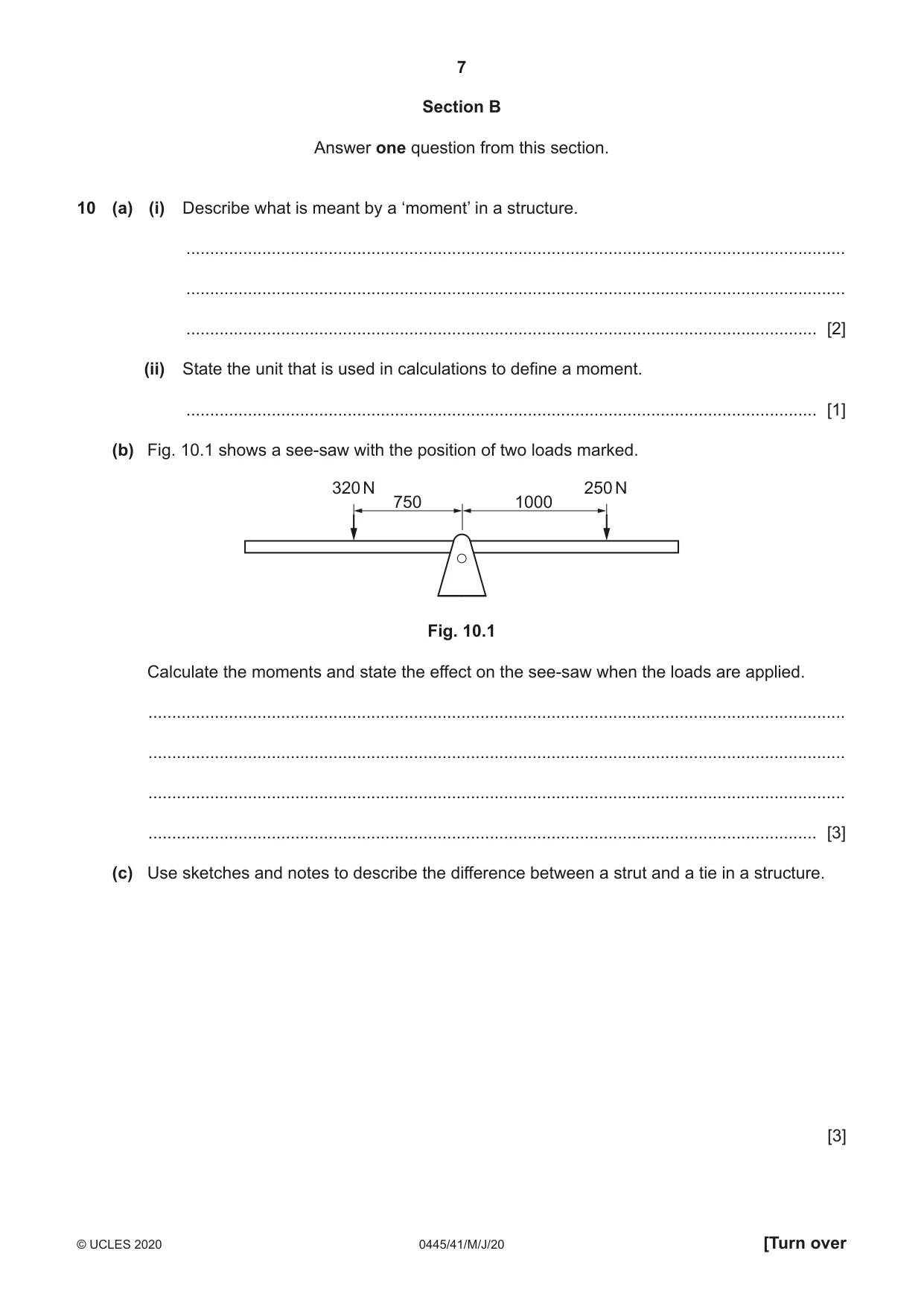
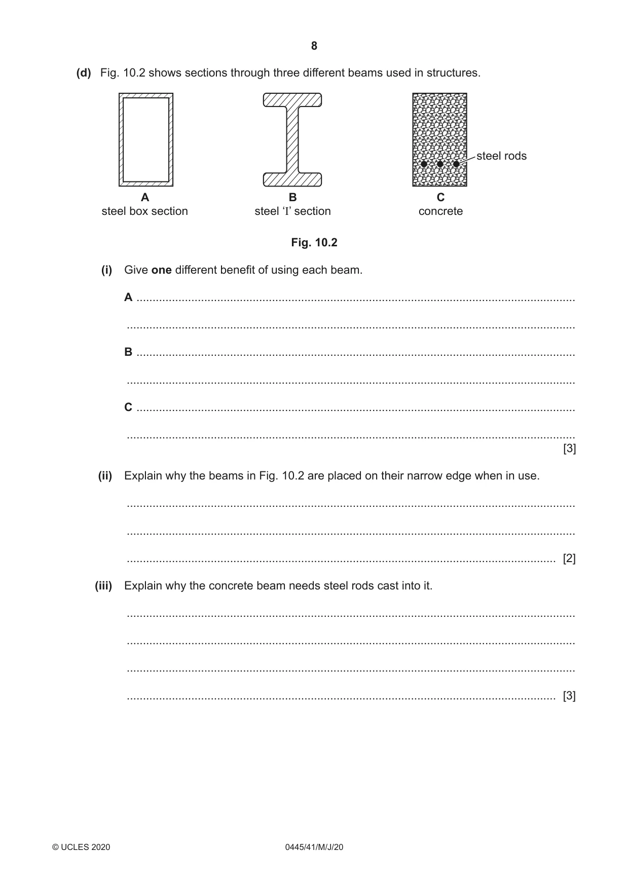
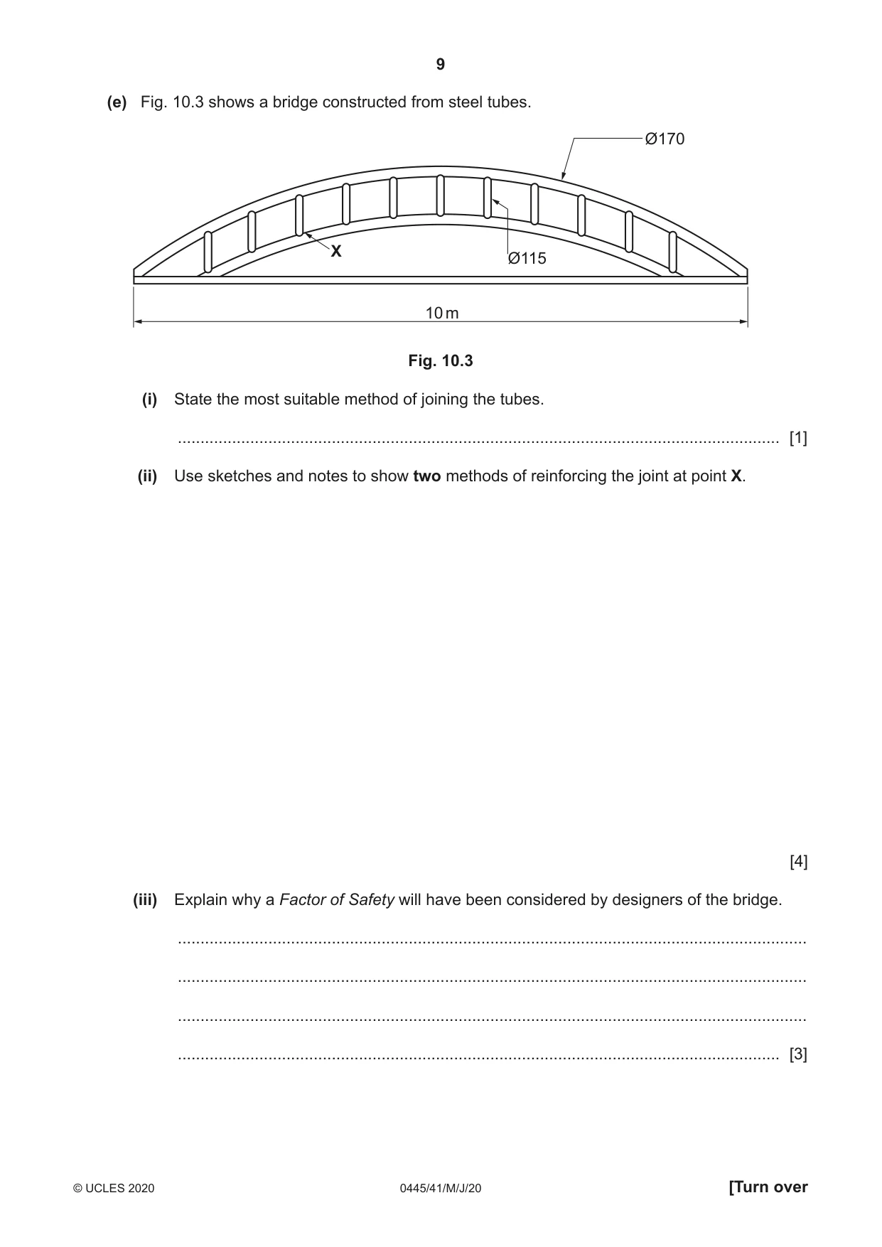
10 (a) (i) Describe what is meant by a ‘moment’ in a structure. ........................................................................................................................................... ........................................................................................................................................... ..................................................................................................................................... [2] (ii) State the unit that is used in calculations to define a moment. ..................................................................................................................................... [1] (b) Fig. 10.1 shows a see-saw with the position of two loads marked. 320 N 250 N 750 1000 Fig. 10.1 Calculate the moments and state the effect on the see-saw when the loads are applied. ................................................................................................................................................... ................................................................................................................................................... ................................................................................................................................................... ............................................................................................................................................. [3] (c) Use sketches and notes to describe the difference between a strut and a tie in a structure. [3] (d) Fig. 10.2 shows sections through three different beams used in structures. steel rods A B C steel box section steel ‘I’ section concrete Fig. 10.2 (i) Give one different benefit of using each beam. A ........................................................................................................................................ ........................................................................................................................................... B ........................................................................................................................................ ........................................................................................................................................... C ........................................................................................................................................ ........................................................................................................................................... [3] (ii) Explain why the beams in Fig. 10.2 are placed on their narrow edge when in use. ........................................................................................................................................... ........................................................................................................................................... ..................................................................................................................................... [2] (iii) Explain why the concrete beam needs steel rods cast into it. ........................................................................................................................................... ........................................................................................................................................... ........................................................................................................................................... ..................................................................................................................................... [3] (e) Fig. 10.3 shows a bridge constructed from steel tubes. Ø170 X Ø115 10 m Fig. 10.3 (i) State the most suitable method of joining the tubes. ..................................................................................................................................... [1] (ii) Use sketches and notes to show two methods of reinforcing the joint at point X. [4] (iii) Explain why a Factor of Safety will have been considered by designers of the bridge. ........................................................................................................................................... ........................................................................................................................................... ........................................................................................................................................... ..................................................................................................................................... [3]
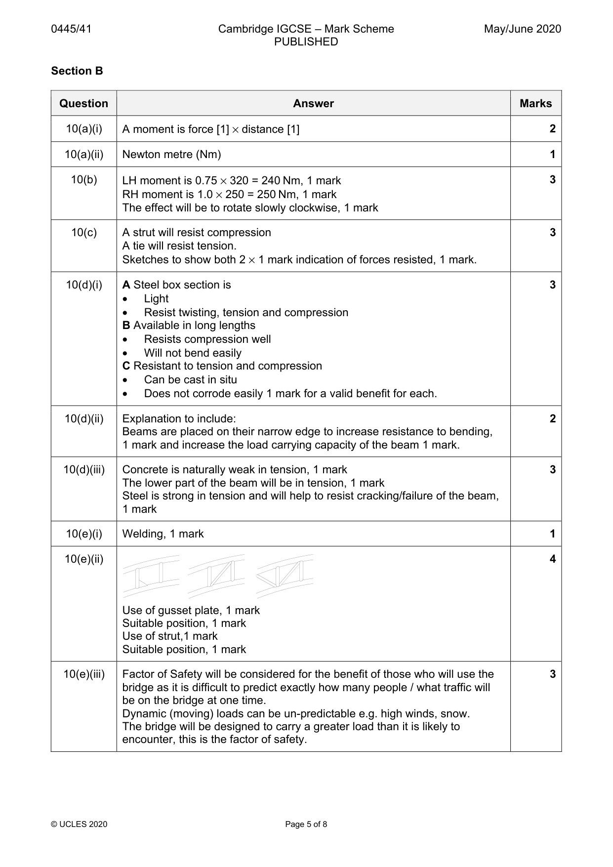
Mark scheme: 10(a)(i) A moment is force [1] × distance [1] 2 10(a)(ii) Newton metre (Nm) 1 10(b) LH moment is 0.75 × 320 = 240 Nm, 1 mark 3 RH moment is 1.0 × 250 = 250 Nm, 1 mark The effect will be to rotate slowly clockwise, 1 mark 10(c) A strut will resist compression 3 A tie will resist tension. Sketches to show both 2 × 1 mark indication of forces resisted, 1 mark. 10(d)(i) A Steel box section is 3 • Light • Resist twisting, tension and compression B Available in long lengths • Resists compression well • Will not bend easily C Resistant to tension and compression • Can be cast in situ • Does not corrode easily 1 mark for a valid benefit for each. 10(d)(ii) Explanation to include: 2 Beams are placed on their narrow edge to increase resistance to bending, 1 mark and increase the load carrying capacity of the beam 1 mark. 10(d)(iii) Concrete is naturally weak in tension, 1 mark 3 The lower part of the beam will be in tension, 1 mark Steel is strong in tension and will help to resist cracking/failure of the beam, 1 mark 10(e)(i) Welding, 1 mark 1 10(e)(ii) 4 Use of gusset plate, 1 mark Suitable position, 1 mark Use of strut,1 mark Suitable position, 1 mark 10(e)(iii) Factor of Safety will be considered for the benefit of those who will use the 3 bridge as it is difficult to predict exactly how many people / what traffic will be on the bridge at one time. Dynamic (moving) loads can be un-predictable e.g. high winds, snow. The bridge will be designed to carry a greater load than it is likely to encounter, this is the factor of safety.
Q11 · Three methods of transmitting motion from one shaft to another
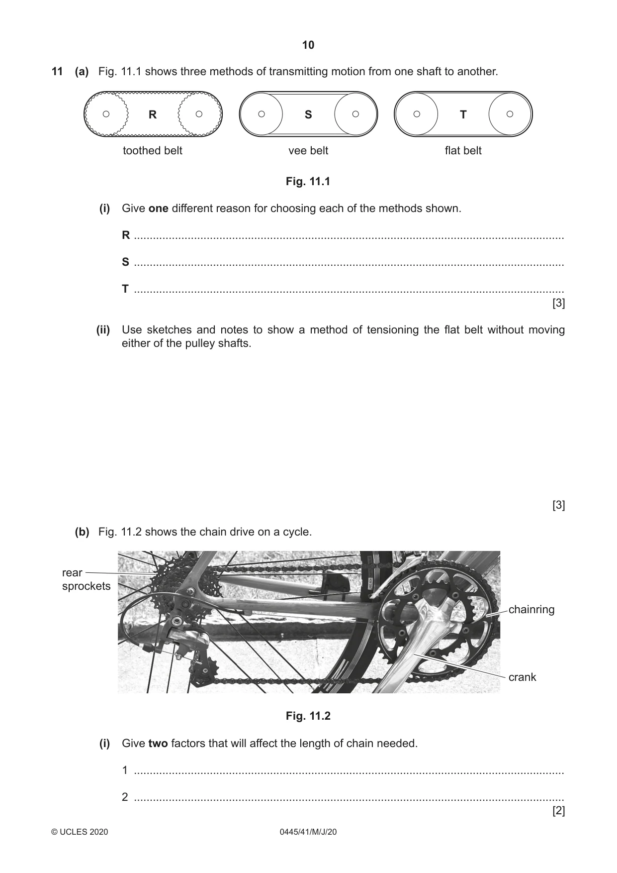
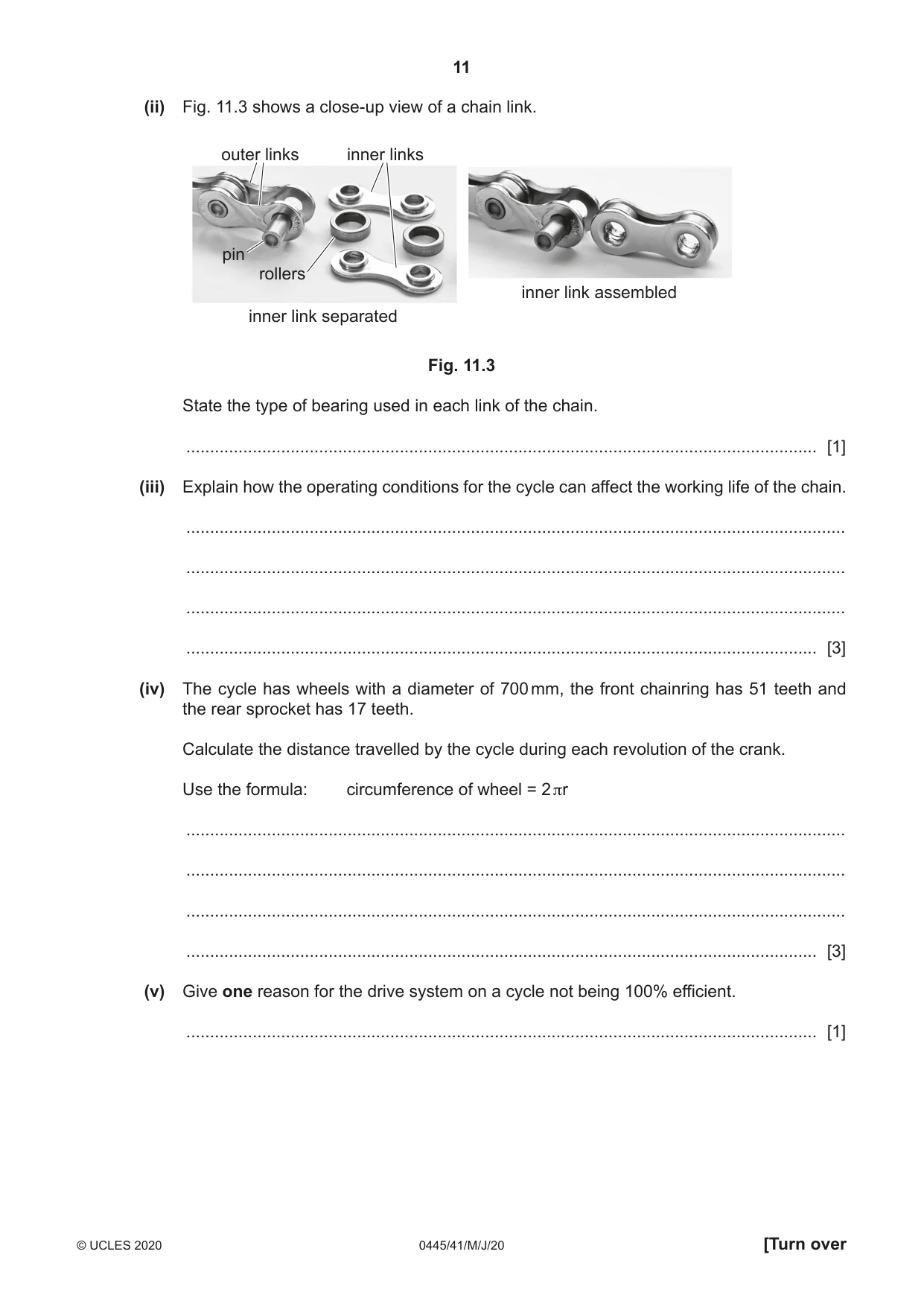
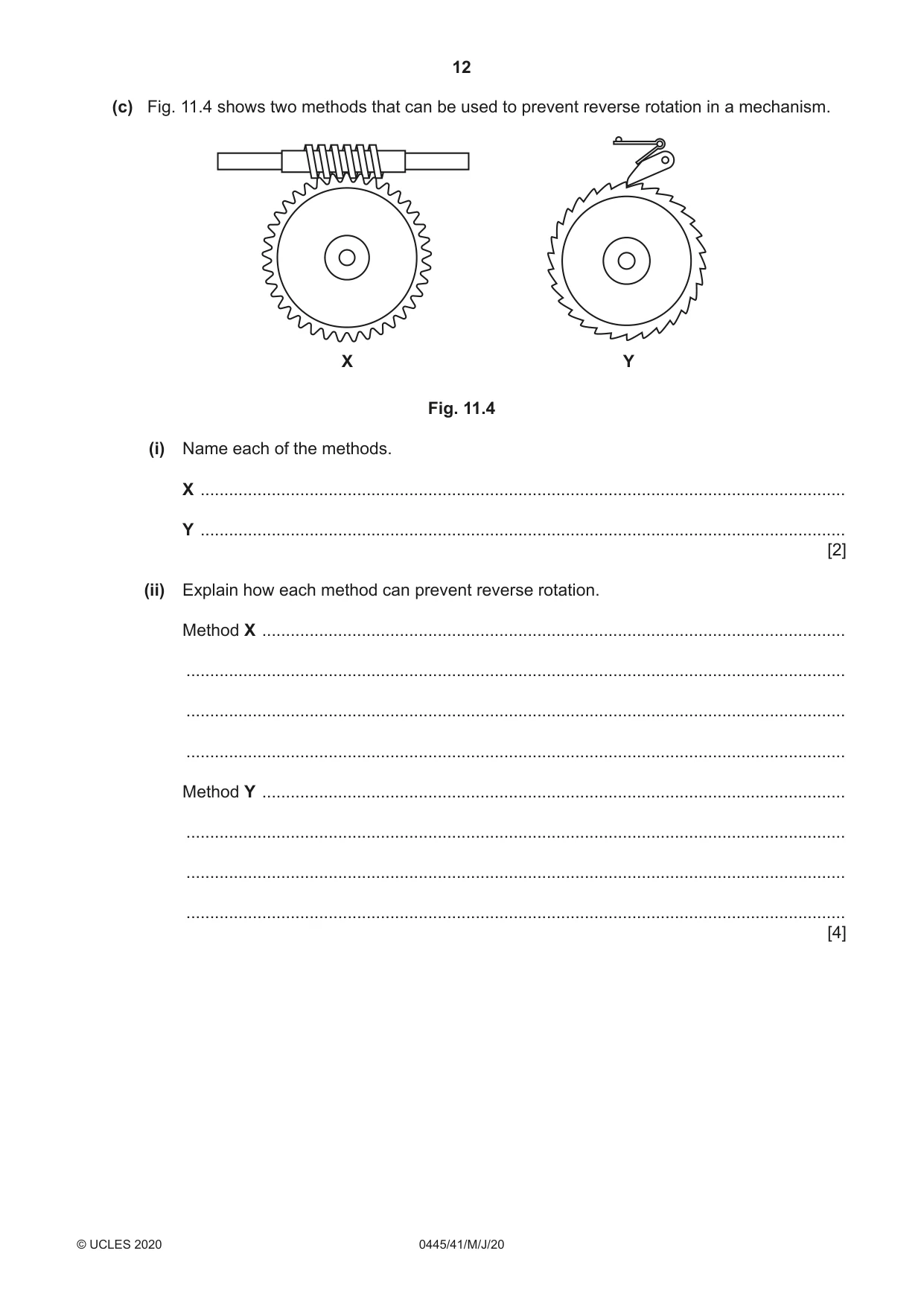
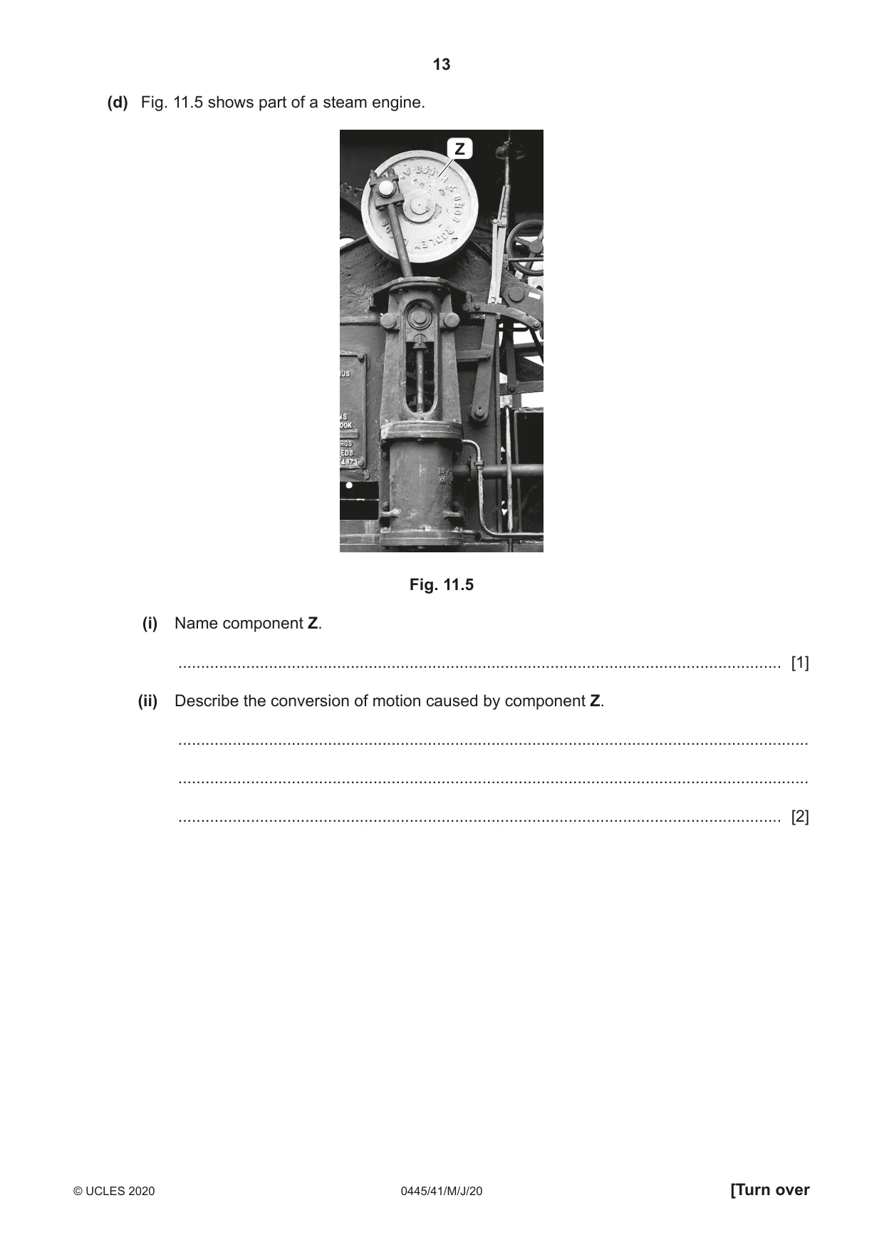
11 (a) Fig. 11.1 shows three methods of transmitting motion from one shaft to another. R S T toothed belt vee belt flat belt Fig. 11.1 (i) Give one different reason for choosing each of the methods shown. R ........................................................................................................................................ S ........................................................................................................................................ T ........................................................................................................................................ [3] (ii) Use sketches and notes to show a method of tensioning the flat belt without moving either of the pulley shafts. [3] (b) Fig. 11.2 shows the chain drive on a cycle. rear sprockets chainring crank Fig. 11.2 (i) Give two factors that will affect the length of chain needed. 1 ........................................................................................................................................ 2 ........................................................................................................................................ [2] (ii) Fig. 11.3 shows a close-up view of a chain link. outer links inner links pin rollers inner link assembled inner link separated Fig. 11.3 State the type of bearing used in each link of the chain. ..................................................................................................................................... [1] (iii) Explain how the operating conditions for the cycle can affect the working life of the chain. ........................................................................................................................................... ........................................................................................................................................... ........................................................................................................................................... ..................................................................................................................................... [3] (iv) The cycle has wheels with a diameter of 700 mm, the front chainring has 51 teeth and the rear sprocket has 17 teeth. Calculate the distance travelled by the cycle during each revolution of the crank. Use the formula: circumference of wheel = 2 πr ........................................................................................................................................... ........................................................................................................................................... ........................................................................................................................................... ..................................................................................................................................... [3] (v) Give one reason for the drive system on a cycle not being 100% efficient. ..................................................................................................................................... [1] (c) Fig. 11.4 shows two methods that can be used to prevent reverse rotation in a mechanism. X Y Fig. 11.4 (i) Name each of the methods. X ........................................................................................................................................ Y ........................................................................................................................................ [2] (ii) Explain how each method can prevent reverse rotation. Method X ........................................................................................................................... ........................................................................................................................................... ........................................................................................................................................... ........................................................................................................................................... Method Y ........................................................................................................................... ........................................................................................................................................... ........................................................................................................................................... ........................................................................................................................................... [4] (d) Fig. 11.5 shows part of a steam engine. Z Fig. 11.5 (i) Name component Z. ..................................................................................................................................... [1] (ii) Describe the conversion of motion caused by component Z. ........................................................................................................................................... ........................................................................................................................................... ..................................................................................................................................... [2]
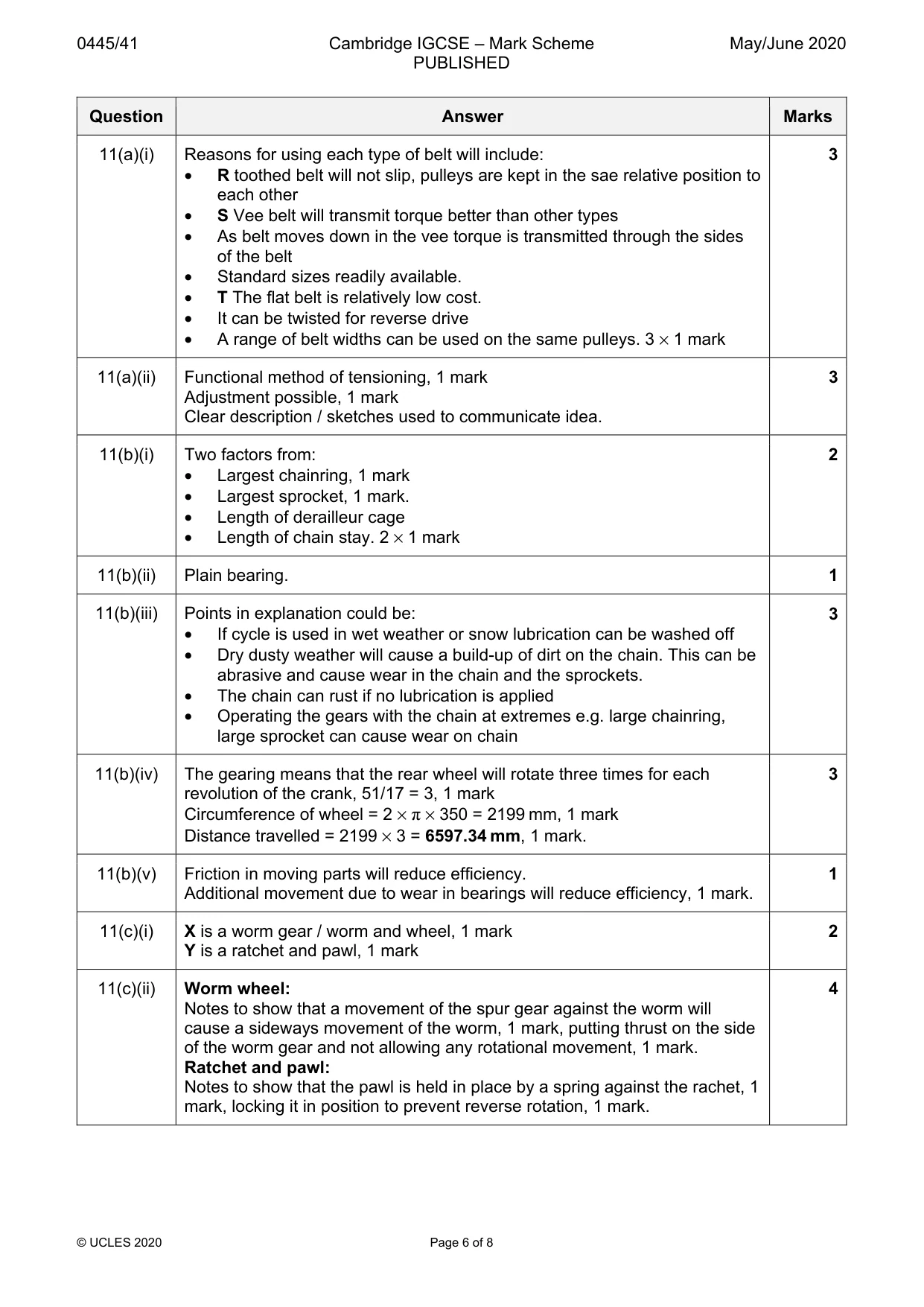
Mark scheme: 11(a)(i) Reasons for using each type of belt will include: 3 • R toothed belt will not slip, pulleys are kept in the sae relative position to each other • S Vee belt will transmit torque better than other types • As belt moves down in the vee torque is transmitted through the sides of the belt • Standard sizes readily available. • T The flat belt is relatively low cost. • It can be twisted for reverse drive • A range of belt widths can be used on the same pulleys. 3 × 1 mark 11(a)(ii) Functional method of tensioning, 1 mark 3 Adjustment possible, 1 mark Clear description / sketches used to communicate idea. 11(b)(i) Two factors from: 2 • Largest chainring, 1 mark • Largest sprocket, 1 mark. • Length of derailleur cage • Length of chain stay. 2 × 1 mark 11(b)(ii) Plain bearing. 1 11(b)(iii) Points in explanation could be: 3 • If cycle is used in wet weather or snow lubrication can be washed off • Dry dusty weather will cause a build-up of dirt on the chain. This can be abrasive and cause wear in the chain and the sprockets. • The chain can rust if no lubrication is applied • Operating the gears with the chain at extremes e.g. large chainring, large sprocket can cause wear on chain 11(b)(iv) The gearing means that the rear wheel will rotate three times for each 3 revolution of the crank, 51/17 = 3, 1 mark Circumference of wheel = 2 × π × 350 = 2199 mm, 1 mark Distance travelled = 2199 × 3 = 6597.34 mm, 1 mark. 11(b)(v) Friction in moving parts will reduce efficiency. 1 Additional movement due to wear in bearings will reduce efficiency, 1 mark. 11(c)(i) X is a worm gear / worm and wheel, 1 mark 2 Y is a ratchet and pawl, 1 mark 11(c)(ii) Worm wheel: 4 Notes to show that a movement of the spur gear against the worm will cause a sideways movement of the worm, 1 mark, putting thrust on the side of the worm gear and not allowing any rotational movement, 1 mark. Ratchet and pawl: Notes to show that the pawl is held in place by a spring against the rachet, 1 mark, locking it in position to prevent reverse rotation, 1 mark. 11(d)(i) Component Z is a crankshaft, 1 mark. 1 11(d)(ii) Reciprocation motion in the piston is converted to rotary motion in the 2 crankshaft, 2 marks.
Q12 · A design for a printed circuit board (PCB) layout
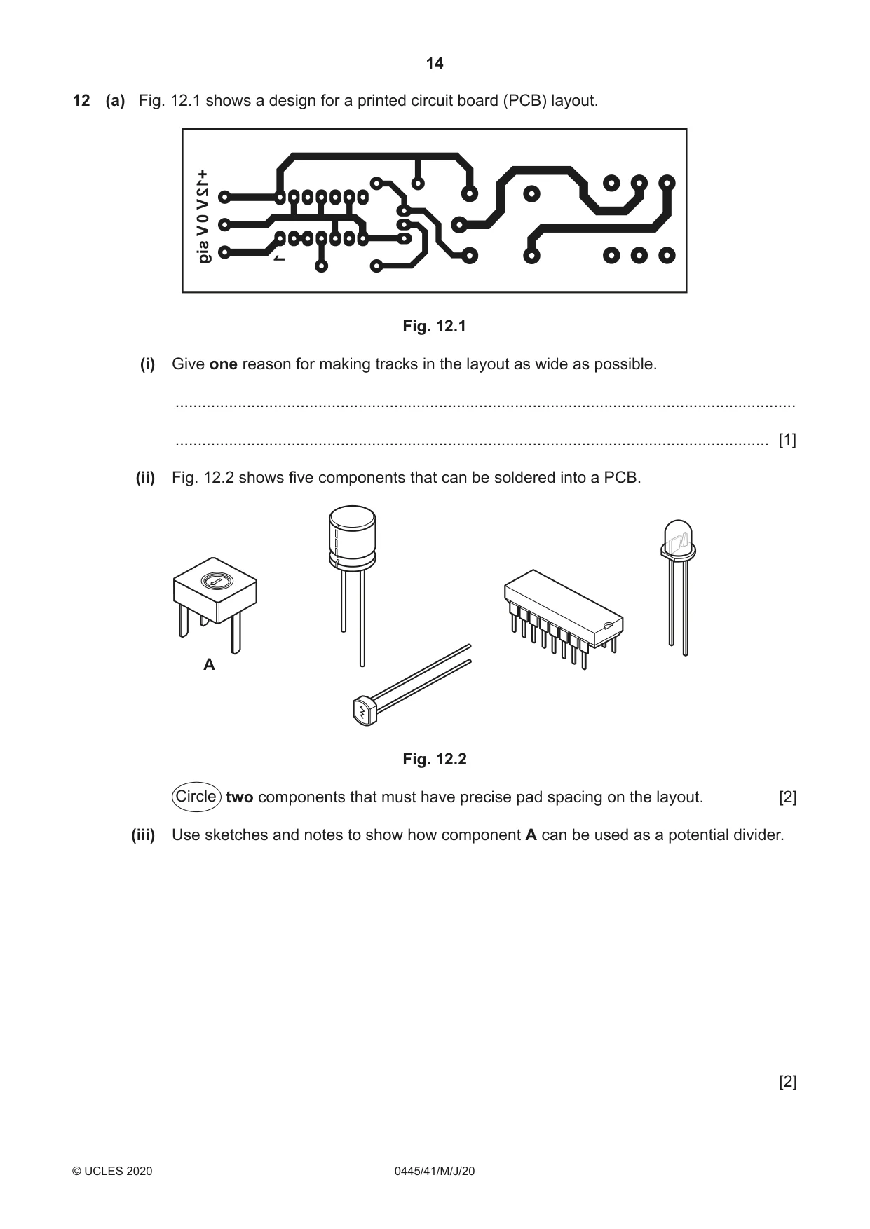
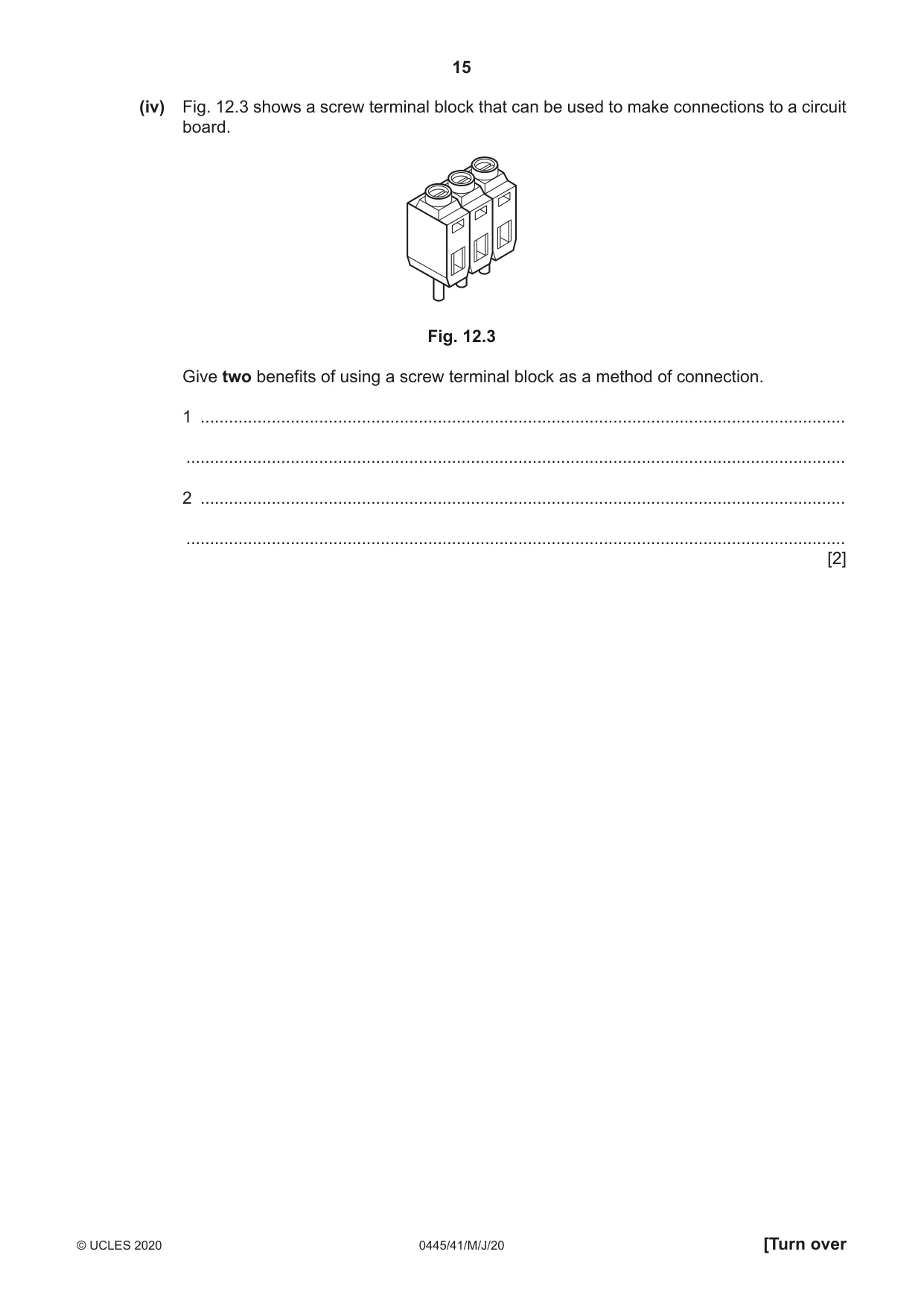
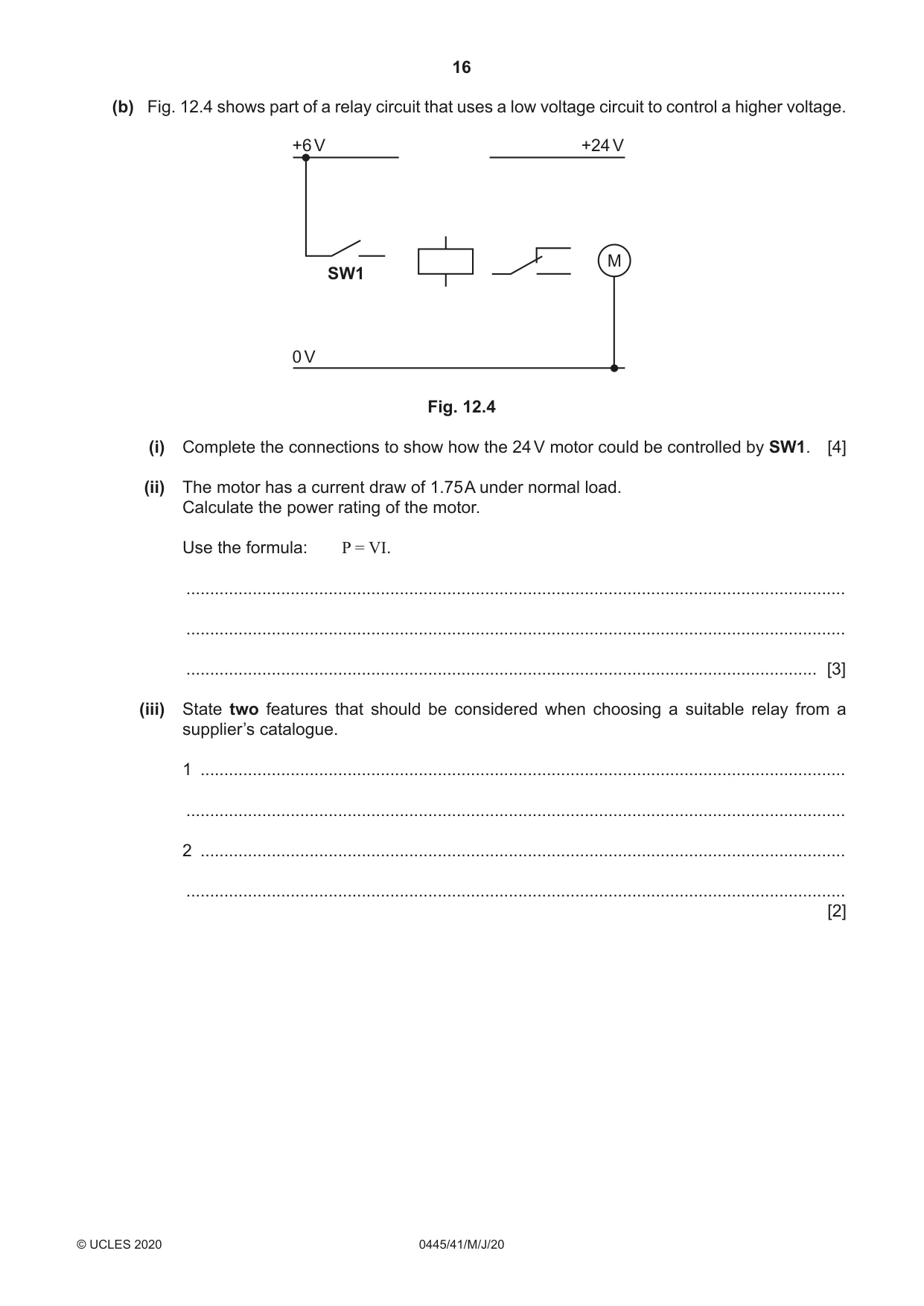
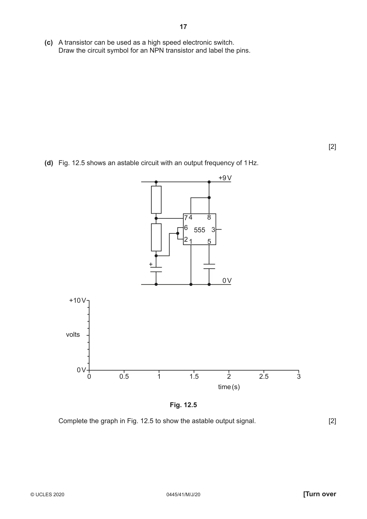
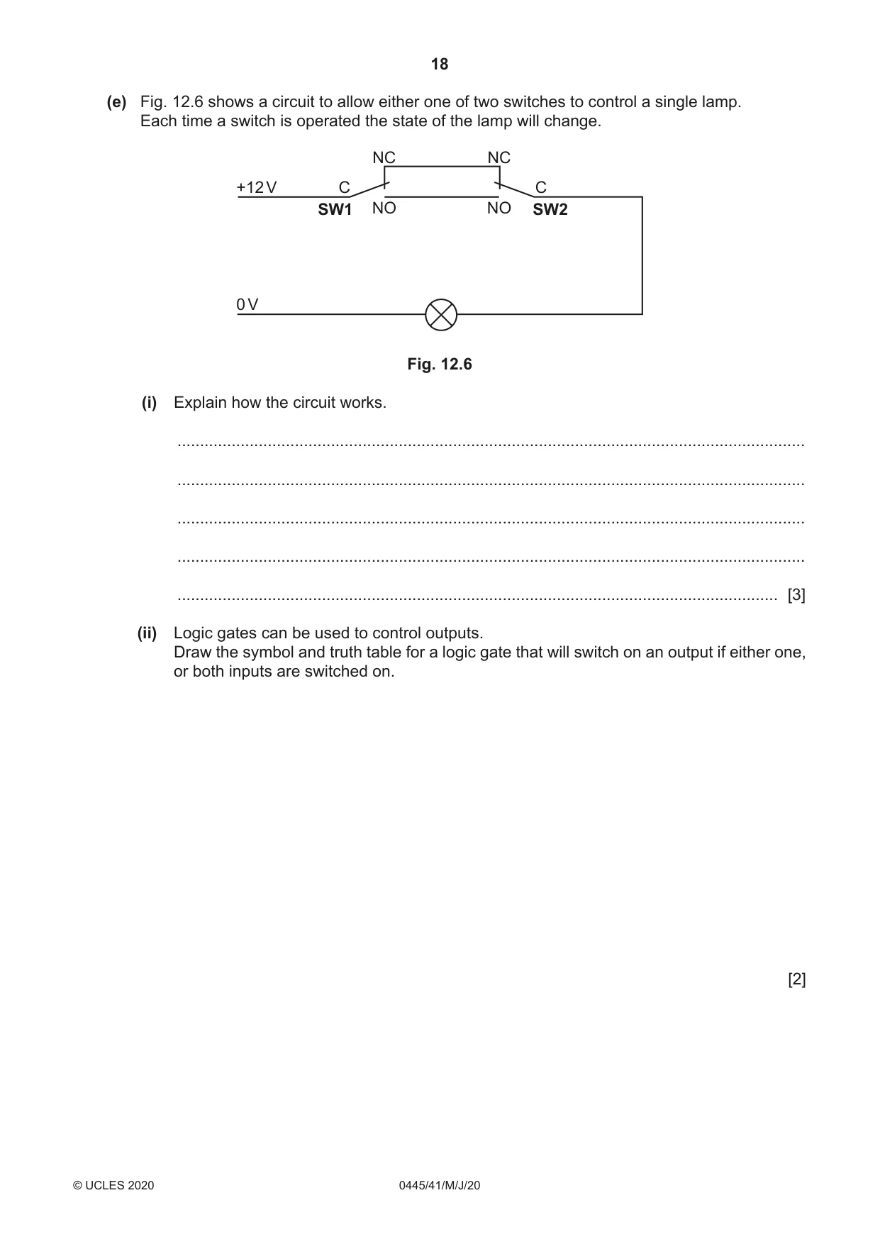
12 (a) Fig. 12.1 shows a design for a printed circuit board (PCB) layout. +12 V 0 V sig 1 Fig. 12.1 (i) Give one reason for making tracks in the layout as wide as possible. ........................................................................................................................................... ..................................................................................................................................... [1] (ii) Fig. 12.2 shows five components that can be soldered into a PCB. A Fig. 12.2 Circle two components that must have precise pad spacing on the layout. [2] (iii) Use sketches and notes to show how component A can be used as a potential divider. [2] (iv) Fig. 12.3 shows a screw terminal block that can be used to make connections to a circuit board. Fig. 12.3 Give two benefits of using a screw terminal block as a method of connection. 1 ........................................................................................................................................ ........................................................................................................................................... 2 ........................................................................................................................................ ........................................................................................................................................... [2] (b) Fig. 12.4 shows part of a relay circuit that uses a low voltage circuit to control a higher voltage. +6 V +24 V M SW1 0 V Fig. 12.4 (i) Complete the connections to show how the 24 V motor could be controlled by SW1. [4] (ii) The motor has a current draw of 1.75 A under normal load. Calculate the power rating of the motor. Use the formula: P = VI. ........................................................................................................................................... ........................................................................................................................................... ..................................................................................................................................... [3] (iii) State two features that should be considered when choosing a suitable relay from a supplier’s catalogue. 1 ........................................................................................................................................ ........................................................................................................................................... 2 ........................................................................................................................................ ........................................................................................................................................... [2]
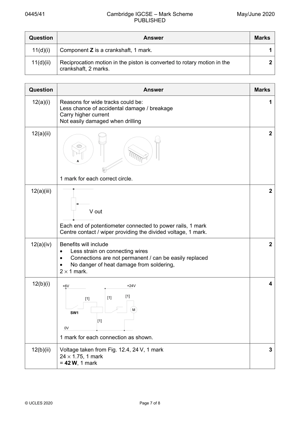
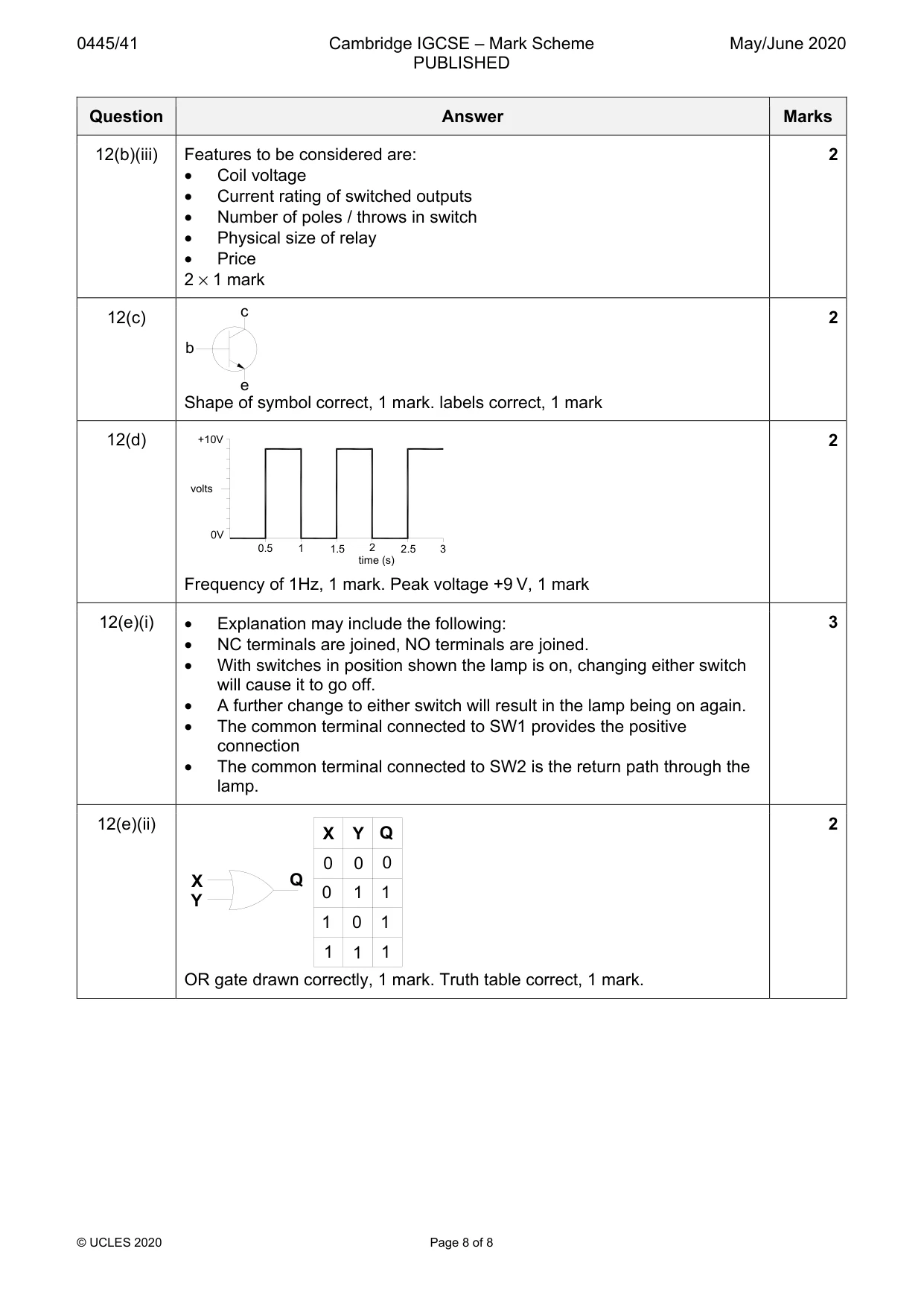
Mark scheme: 12(a)(i) Reasons for wide tracks could be: 1 Less chance of accidental damage / breakage Carry higher current Not easily damaged when drilling 12(a)(ii) 2 A 1 mark for each correct circle. 12(a)(iii) 2 V out Each end of potentiometer connected to power rails, 1 mark Centre contact / wiper providing the divided voltage, 1 mark. 12(a)(iv) Benefits will include 2 • Less strain on connecting wires • Connections are not permanent / can be easily replaced • No danger of heat damage from soldering, 2 × 1 mark. 12(b)(i) +6V +24V 4 [1] [1] [1] SW1 [1] 0V 1 mark for each connection as shown. 12(b)(ii) Voltage taken from Fig. 12.4, 24 V, 1 mark 3 24 × 1.75, 1 mark = 42 W, 1 mark 12(b)(iii) Features to be considered are: 2 • Coil voltage • Current rating of switched outputs • Number of poles / throws in switch • Physical size of relay • Price 2 × 1 mark 12(c) 2 b e Shape of symbol correct, 1 mark. labels correct, 1 mark 12(d) +10V 2 volts 0V 0.5 1 1.5 2 2.5 3 time (s) Frequency of 1Hz, 1 mark. Peak voltage +9 V, 1 mark 12(e)(i) • Explanation may include the following: 3 • NC terminals are joined, NO terminals are joined. • With switches in position shown the lamp is on, changing either switch will cause it to go off. • A further change to either switch will result in the lamp being on again. • The common terminal connected to SW1 provides the positive connection • The common terminal connected to SW2 is the return path through the lamp. 12(e)(ii) 2 X Y Q 0 0 0 X Q 0 1 1 Y 1 0 1 1 1 1 OR gate drawn correctly, 1 mark. Truth table correct, 1 mark.
What was in this paper
The subtopics covered by these 12 questions, and how many questions each got. Open one in a new tab to see every Cambridge question on it.