Cambridge IGCSE Design and Technology 0445 — 2023 Oct/Nov Paper 4 · Variant 1
0445/41/O/N/23 · 11 questions · 50 marks · ≈56 min
The question paper and its mark scheme, free to read here and free to download. This is Cambridge’s own paper, exactly as it was sat.
Question paper20 pages
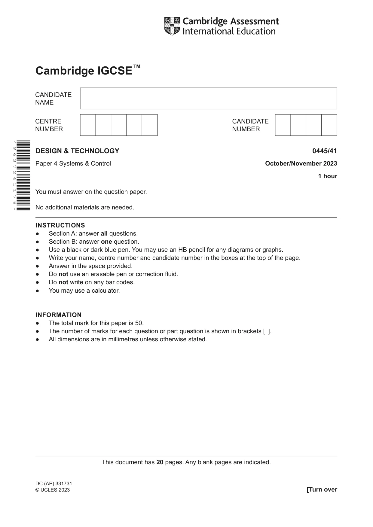



Mark scheme15 pages
Answers below. Sit the paper first if you are practising.
Questions as text
Q1 · Part of the steel frame structure of an industrial building
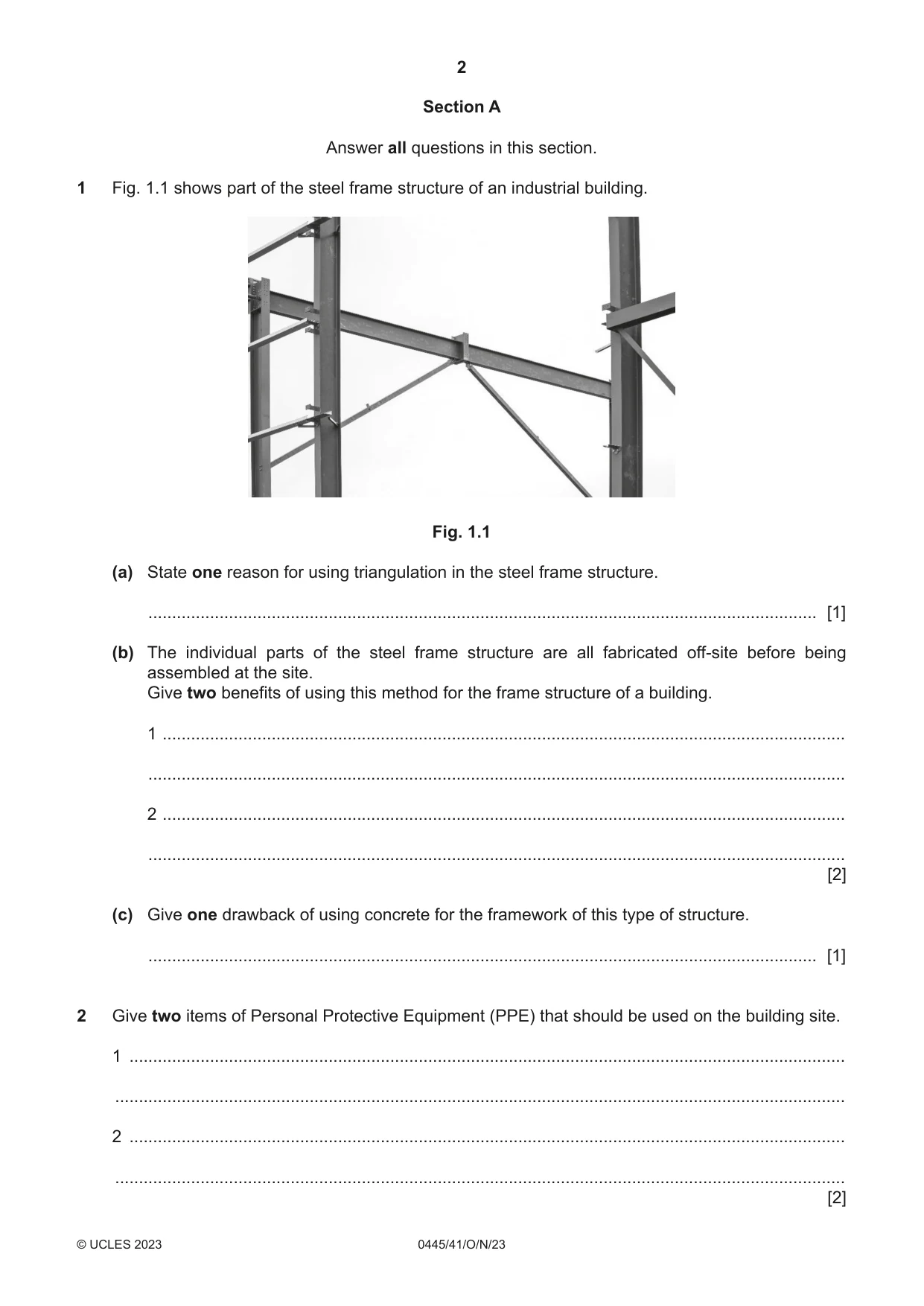
1 Fig. 1.1 shows part of the steel frame structure of an industrial building. Fig. 1.1 (a) State one reason for using triangulation in the steel frame structure. ............................................................................................................................................. [1] (b) The individual parts of the steel frame structure are all fabricated off-site before being assembled at the site. Give two benefits of using this method for the frame structure of a building. 1 ................................................................................................................................................ ................................................................................................................................................... 2 ................................................................................................................................................ ................................................................................................................................................... [2] (c) Give one drawback of using concrete for the framework of this type of structure. ............................................................................................................................................. [1]
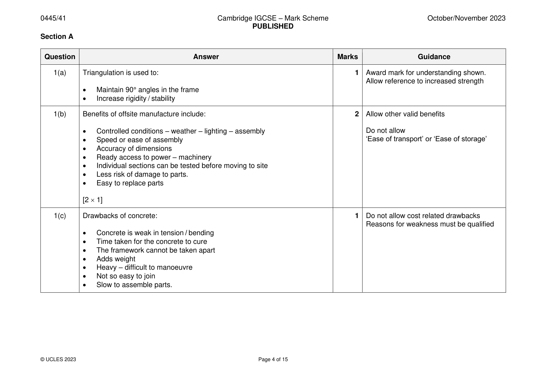
Mark scheme: Question Answer Marks Guidance 1(a) Triangulation is used to: 1 Award mark for understanding shown. Allow reference to increased strength • Maintain 90° angles in the frame • Increase rigidity / stability 1(b) Benefits of offsite manufacture include: 2 Allow other valid benefits • Controlled conditions – weather – lighting – assembly Do not allow • Speed or ease of assembly ‘Ease of transport’ or ‘Ease of storage’ • Accuracy of dimensions • Ready access to power – machinery • Individual sections can be tested before moving to site • Less risk of damage to parts. • Easy to replace parts [2 1] 1(c) Drawbacks of concrete: 1 Do not allow cost related drawbacks Reasons for weakness must be qualified • Concrete is weak in tension / bending • Time taken for the concrete to cure • The framework cannot be taken apart • Adds weight • Heavy – difficult to manoeuvre • Not so easy to join • Slow to assemble parts.
Q2 · Give two items of Personal Protective Equipment (PPE) that should be used on the building…
2 Give two items of Personal Protective Equipment (PPE) that should be used on the building site. 1 ....................................................................................................................................................... .......................................................................................................................................................... 2 ....................................................................................................................................................... .......................................................................................................................................................... [2]
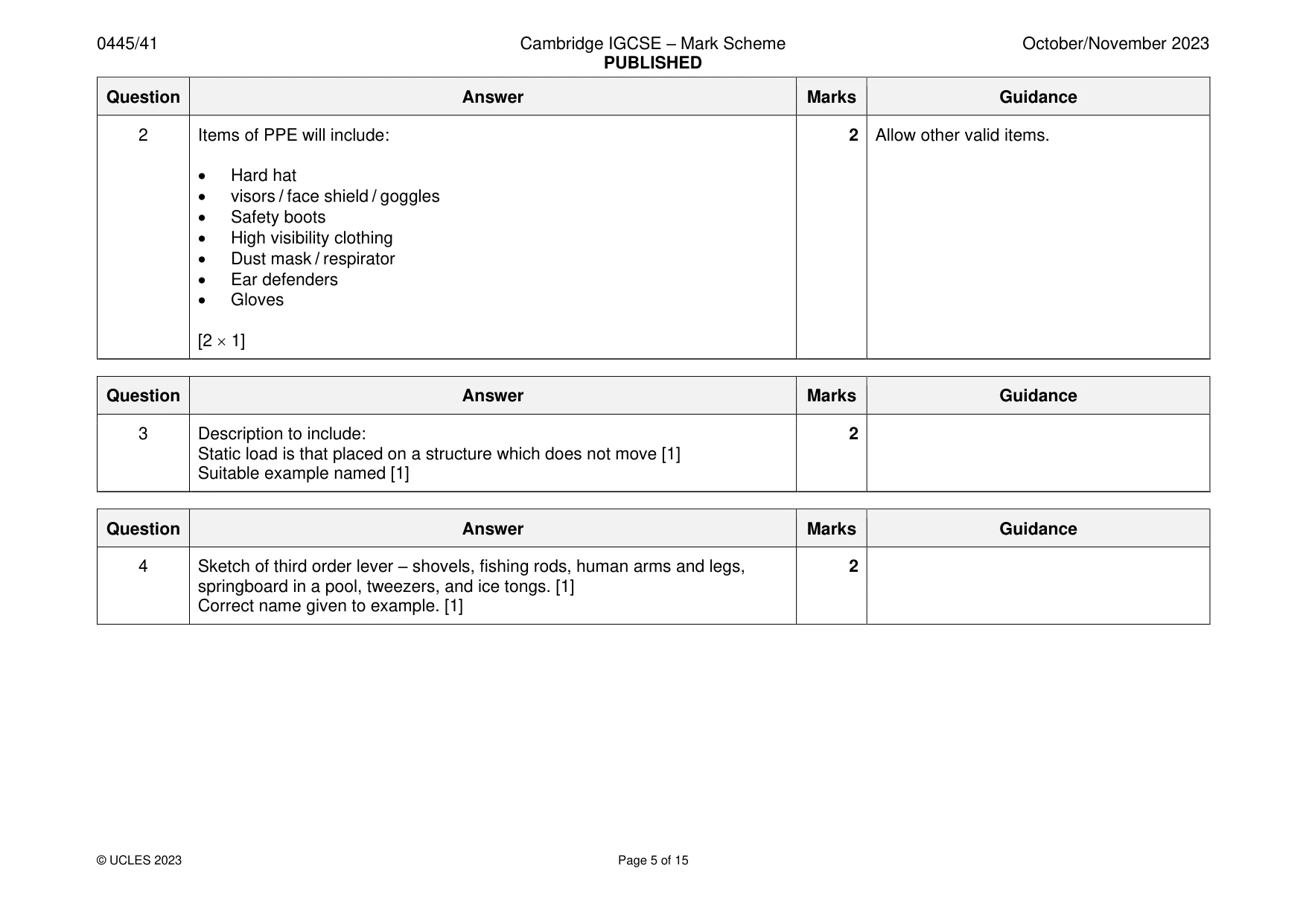
Mark scheme: 2 Items of PPE will include: 2 Allow other valid items. • Hard hat • visors / face shield / goggles • Safety boots • High visibility clothing • Dust mask / respirator • Ear defenders • Gloves [2 1]
Q3 · Describe, using an example, the meaning of static load in a structure
3 Describe, using an example, the meaning of static load in a structure. .......................................................................................................................................................... .......................................................................................................................................................... .................................................................................................................................................... [2]
Mark scheme: 3 Description to include: 2 Static load is that placed on a structure which does not move [1] Suitable example named [1]
Q4 · Sketch and name one example of a third order lever
4 Sketch and name one example of a third order lever. [2]
Mark scheme: 4 Sketch of third order lever – shovels, fishing rods, human arms and legs, 2 springboard in a pool, tweezers, and ice tongs. [1] Correct name given to example. [1]
Q5 · A linkage used on a front loader truck
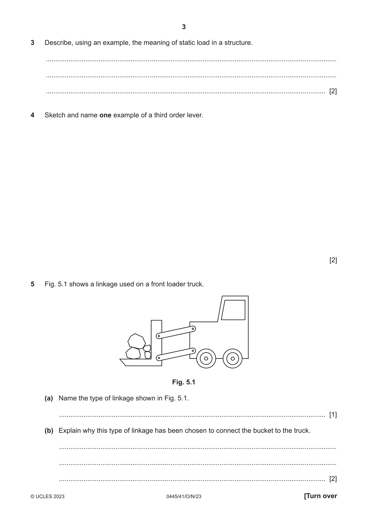
5 Fig. 5.1 shows a linkage used on a front loader truck. Fig. 5.1 (a) Name the type of linkage shown in Fig. 5.1. ............................................................................................................................................. [1] (b) Explain why this type of linkage has been chosen to connect the bucket to the truck. ................................................................................................................................................... ................................................................................................................................................... ............................................................................................................................................. [2] (c) Use sketches and notes to show a different type of linkage. [2]
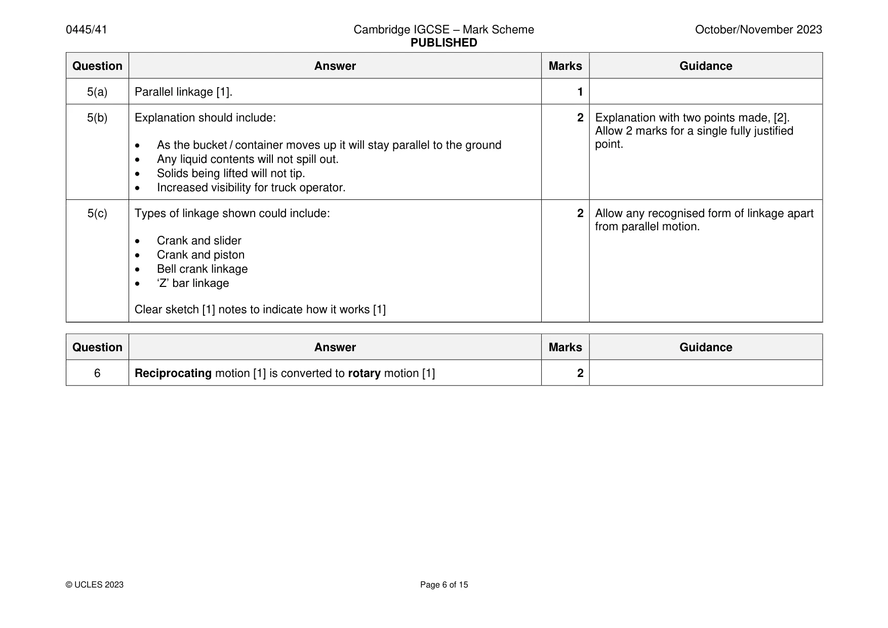
Mark scheme: 5(a) Parallel linkage [1]. 1 5(b) Explanation should include: 2 Explanation with two points made, [2]. Allow 2 marks for a single fully justified • As the bucket / container moves up it will stay parallel to the ground point. • Any liquid contents will not spill out. • Solids being lifted will not tip. • Increased visibility for truck operator. 5(c) Types of linkage shown could include: 2 Allow any recognised form of linkage apart from parallel motion. • Crank and slider • Crank and piston • Bell crank linkage • ‘Z’ bar linkage Clear sketch [1] notes to indicate how it works [1]
Q6 · A simplified line drawing of a small internal combustion (IC) engine
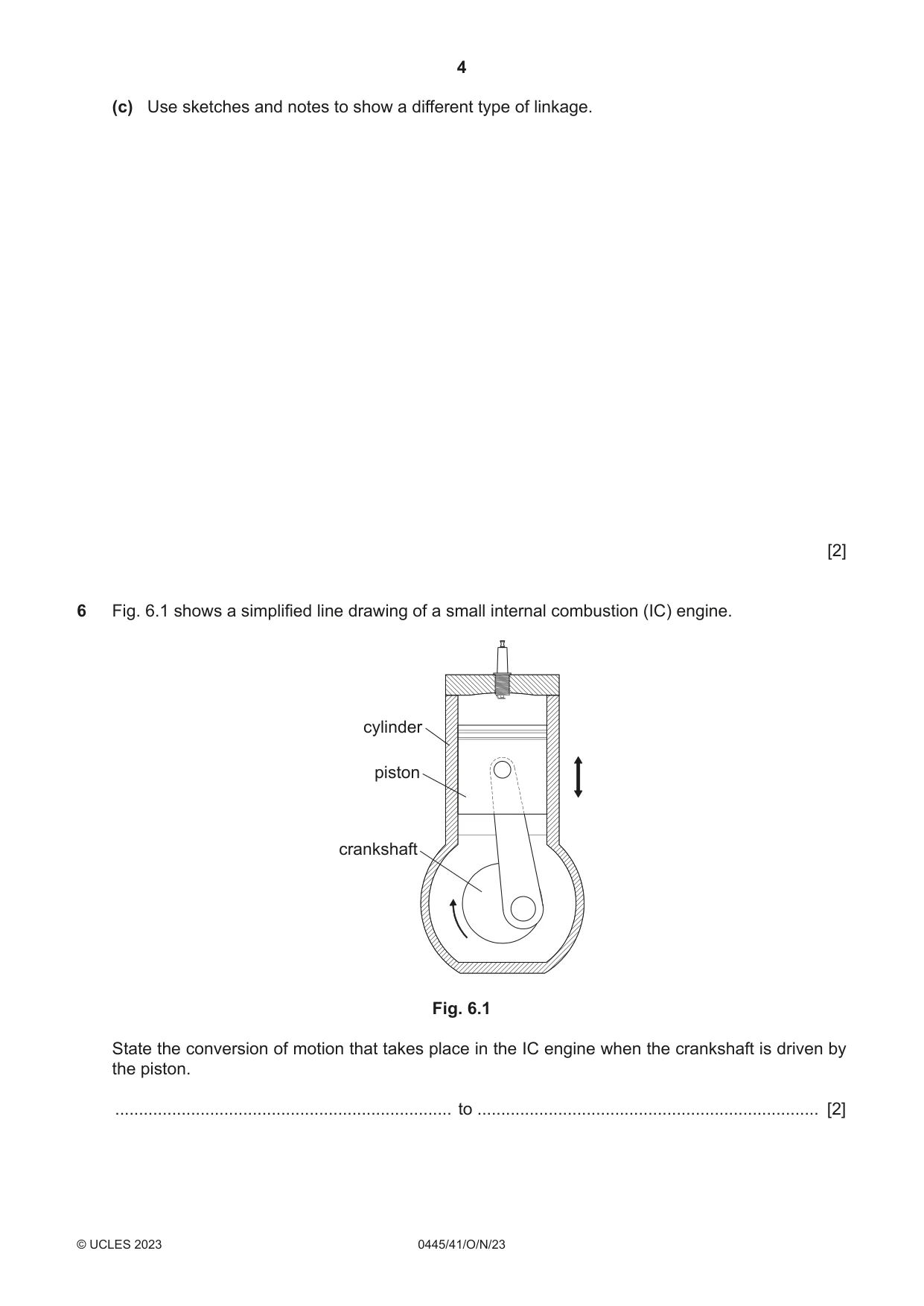
6 Fig. 6.1 shows a simplified line drawing of a small internal combustion (IC) engine. cylinder piston crankshaft Fig. 6.1 State the conversion of motion that takes place in the IC engine when the crankshaft is driven by the piston. ....................................................................... to ........................................................................ [2]
Mark scheme: 6 Reciprocating motion [1] is converted to rotary motion [1] 2
Q7 · Part of an electronic circuit
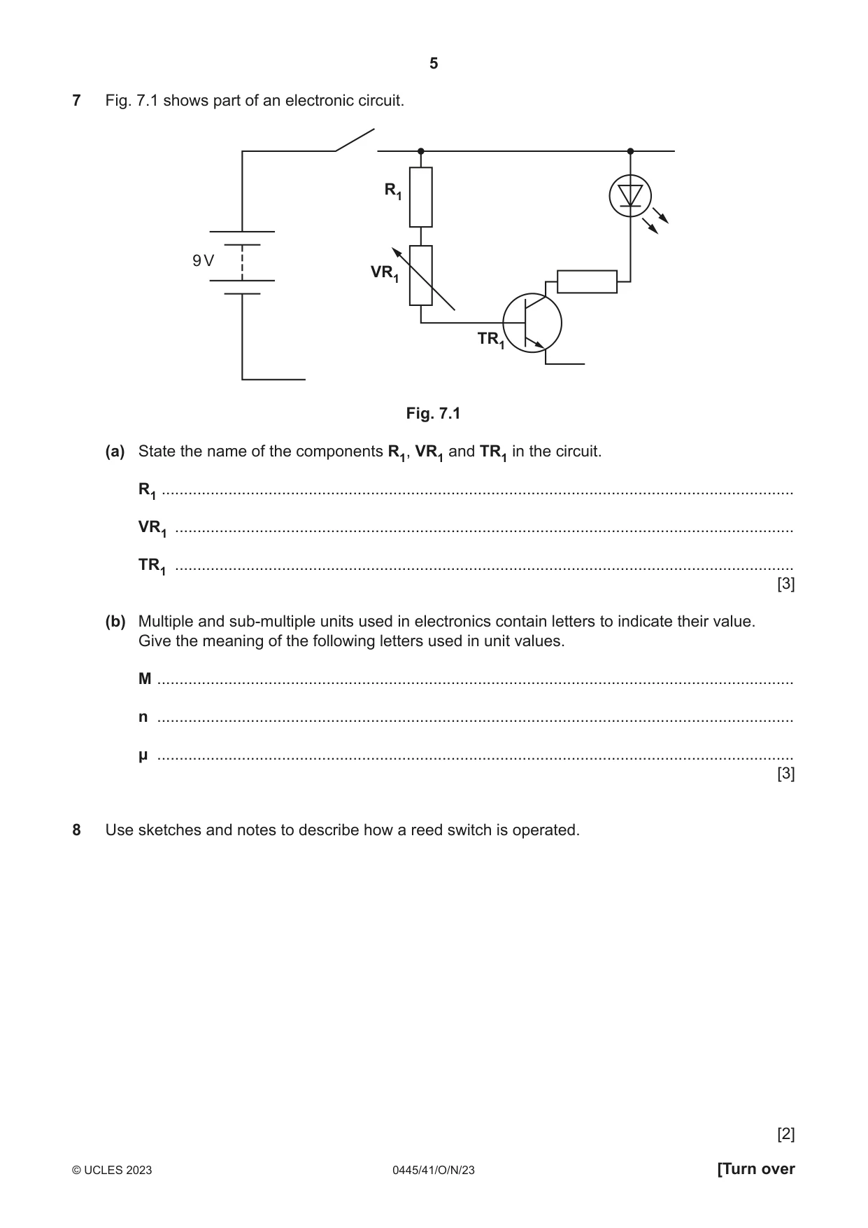
7 Fig. 7.1 shows part of an electronic circuit. R1 9 V VR1 TR1 Fig. 7.1 (a) State the name of the components R1, VR1 and TR1 in the circuit. R1 .............................................................................................................................................. VR1 ........................................................................................................................................... TR1 ........................................................................................................................................... [3] (b) Multiple and sub-multiple units used in electronics contain letters to indicate their value. Give the meaning of the following letters used in unit values. M ............................................................................................................................................... n ............................................................................................................................................... μ ............................................................................................................................................... [3]
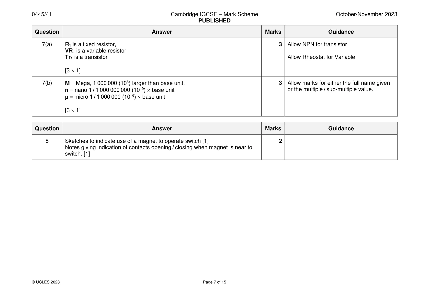
Mark scheme: 7(a) R1 is a fixed resistor, 3 Allow NPN for transistor VR1 is a variable resistor Tr1 is a transistor Allow Rheostat for Variable [3 1] 7(b) M = Mega, 1 000 000 (106) larger than base unit. 3 Allow marks for either the full name given n = nano 1 / 1 000 000 000 (10−9) base unit or the multiple / sub-multiple value. = micro 1 / 1 000 000 (10−6) base unit [3 1]
Q8 · Use sketches and notes to describe how a reed switch is operated
8 Use sketches and notes to describe how a reed switch is operated. [2]
Mark scheme: 8 Sketches to indicate use of a magnet to operate switch [1] 2 Notes giving indication of contacts opening / closing when magnet is near to switch. [1] Section B
Q9 · Part of a model of a roof truss
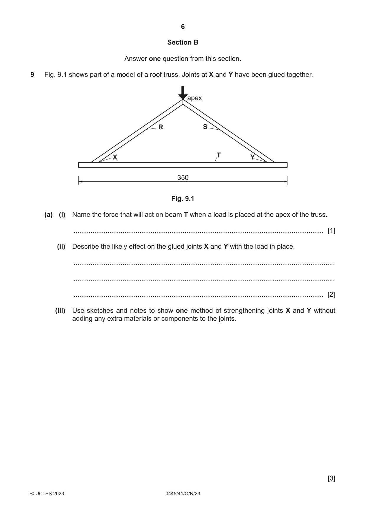
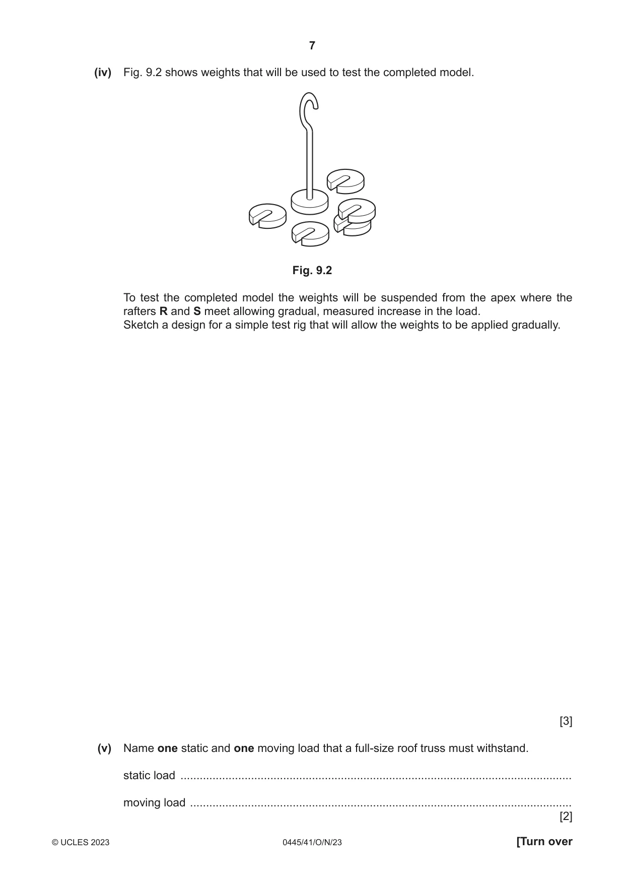
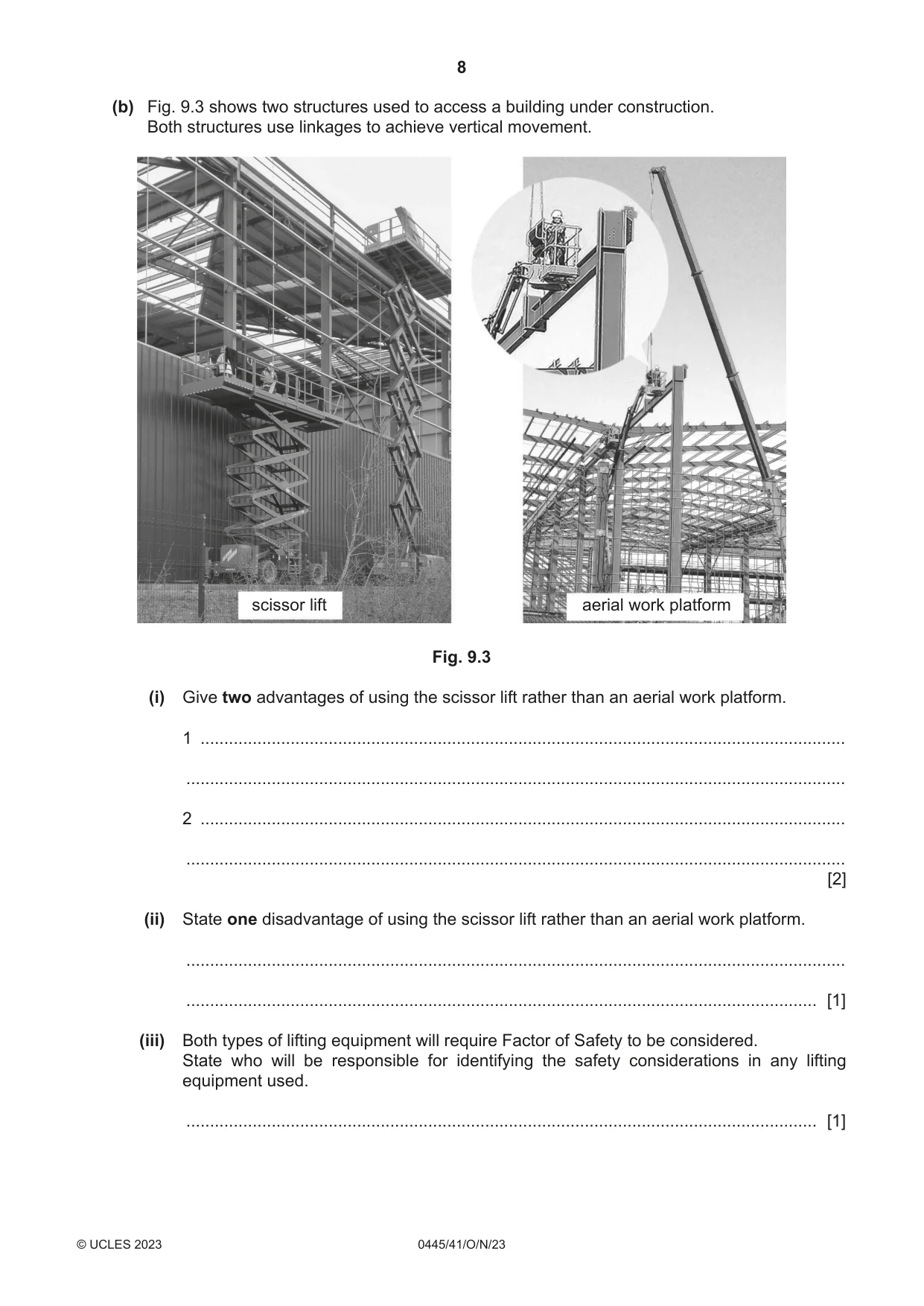
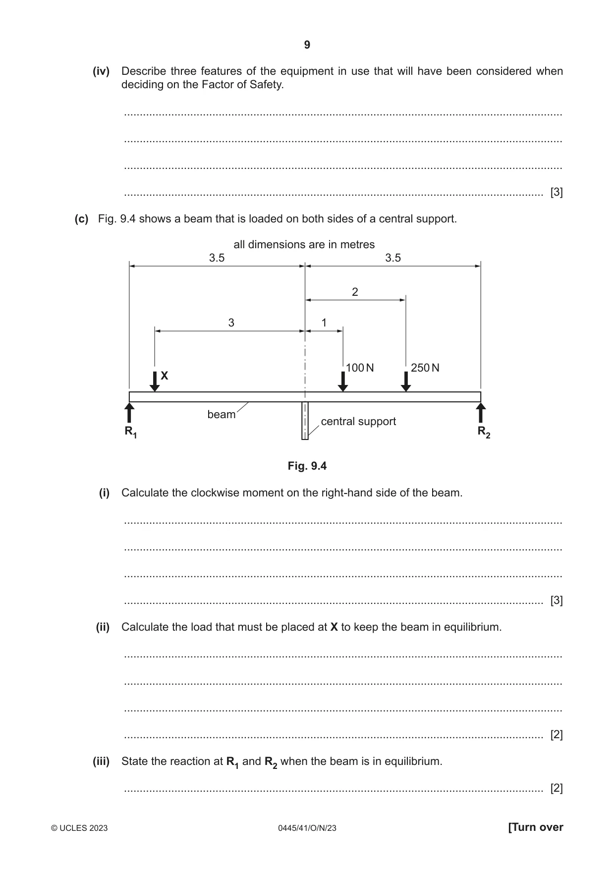
9 Fig. 9.1 shows part of a model of a roof truss. Joints at X and Y have been glued together. apex R S T X Y 350 Fig. 9.1 (a) (i) Name the force that will act on beam T when a load is placed at the apex of the truss. ..................................................................................................................................... [1] (ii) Describe the likely effect on the glued joints X and Y with the load in place. ........................................................................................................................................... ........................................................................................................................................... ..................................................................................................................................... [2] (iii) Use sketches and notes to show one method of strengthening joints X and Y without adding any extra materials or components to the joints. [3] (iv) Fig. 9.2 shows weights that will be used to test the completed model. Fig. 9.2 To test the completed model the weights will be suspended from the apex where the rafters R and S meet allowing gradual, measured increase in the load. Sketch a design for a simple test rig that will allow the weights to be applied gradually. [3] (v) Name one static and one moving load that a full-size roof truss must withstand. static load .......................................................................................................................... moving load ....................................................................................................................... [2] (b) Fig. 9.3 shows two structures used to access a building under construction. Both structures use linkages to achieve vertical movement. scissor lift aerial work platform Fig. 9.3 (i) Give two advantages of using the scissor lift rather than an aerial work platform. 1 ........................................................................................................................................ ........................................................................................................................................... 2 ........................................................................................................................................ ........................................................................................................................................... [2] (ii) State one disadvantage of using the scissor lift rather than an aerial work platform. ........................................................................................................................................... ..................................................................................................................................... [1] (iii) Both types of lifting equipment will require Factor of Safety to be considered. State who will be responsible for identifying the safety considerations in any lifting equipment used. ..................................................................................................................................... [1] (iv) Describe three features of the equipment in use that will have been considered when deciding on the Factor of Safety. ........................................................................................................................................... ........................................................................................................................................... ........................................................................................................................................... ..................................................................................................................................... [3] (c) Fig. 9.4 shows a beam that is loaded on both sides of a central support. all dimensions are in metres 3.5 3.5 2 3 1 100 N 250 N X beam central support R1 R2 Fig. 9.4 (i) Calculate the clockwise moment on the right-hand side of the beam. ........................................................................................................................................... ........................................................................................................................................... ........................................................................................................................................... ..................................................................................................................................... [3] (ii) Calculate the load that must be placed at X to keep the beam in equilibrium. ........................................................................................................................................... ........................................................................................................................................... ........................................................................................................................................... ..................................................................................................................................... [2] (iii) State the reaction at R1 and R2 when the beam is in equilibrium. ..................................................................................................................................... [2]
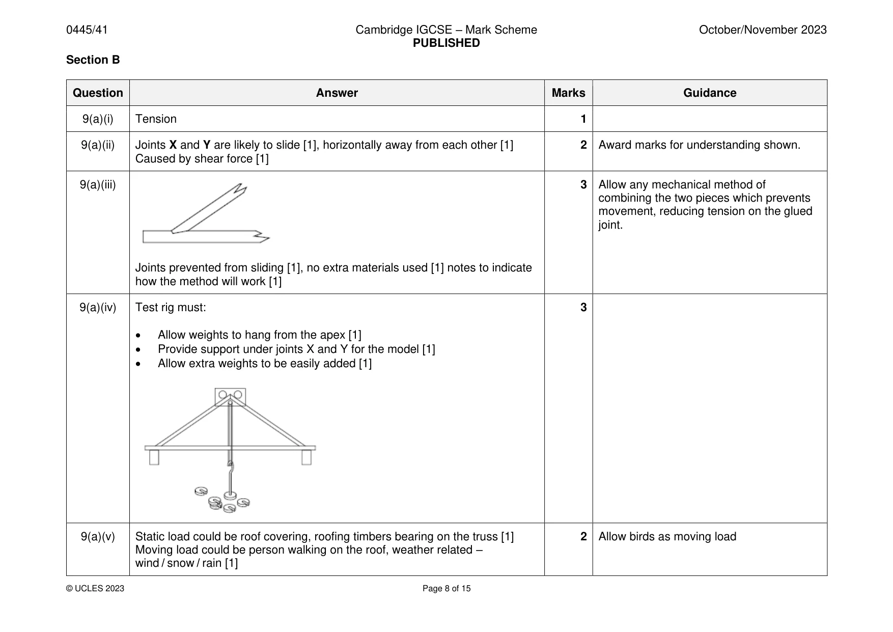
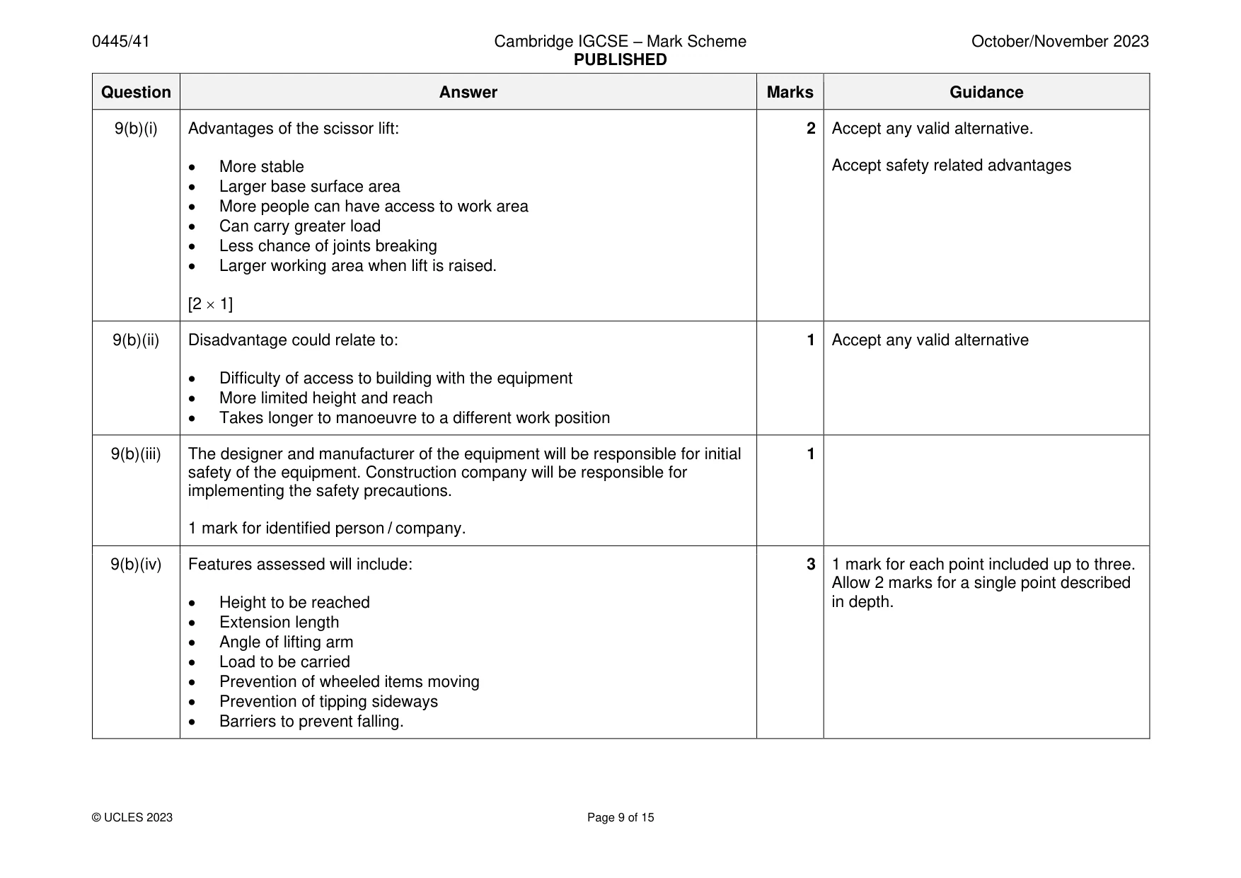
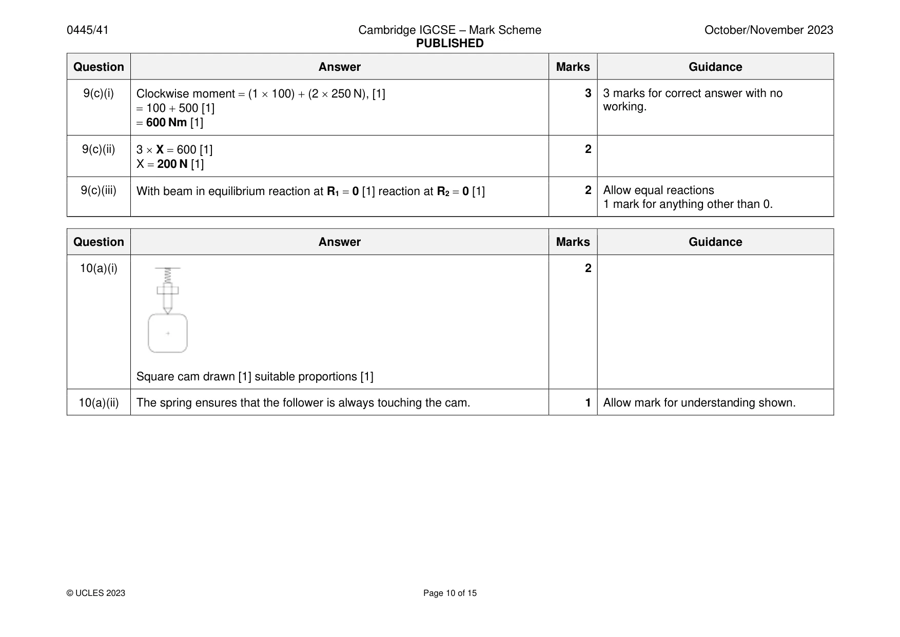
Mark scheme: 9(a)(i) Tension 1 9(a)(ii) Joints X and Y are likely to slide [1], horizontally away from each other [1] 2 Award marks for understanding shown. Caused by shear force [1] 9(a)(iii) 3 Allow any mechanical method of combining the two pieces which prevents movement, reducing tension on the glued joint. Joints prevented from sliding [1], no extra materials used [1] notes to indicate how the method will work [1] 9(a)(iv) Test rig must: 3 • Allow weights to hang from the apex [1] • Provide support under joints X and Y for the model [1] • Allow extra weights to be easily added [1] 9(a)(v) Static load could be roof covering, roofing timbers bearing on the truss [1] 2 Allow birds as moving load Moving load could be person walking on the roof, weather related – wind / snow / rain [1] 9(b)(i) Advantages of the scissor lift: 2 Accept any valid alternative. • More stable Accept safety related advantages • Larger base surface area • More people can have access to work area • Can carry greater load • Less chance of joints breaking • Larger working area when lift is raised. [2 1] 9(b)(ii) Disadvantage could relate to: 1 Accept any valid alternative • Difficulty of access to building with the equipment • More limited height and reach • Takes longer to manoeuvre to a different work position 9(b)(iii) The designer and manufacturer of the equipment will be responsible for initial 1 safety of the equipment. Construction company will be responsible for implementing the safety precautions. 1 mark for identified person / company. 9(b)(iv) Features assessed will include: 3 1 mark for each point included up to three. Allow 2 marks for a single point described • Height to be reached in depth. • Extension length • Angle of lifting arm • Load to be carried • Prevention of wheeled items moving • Prevention of tipping sideways • Barriers to prevent falling. 9(c)(i) Clockwise moment = (1 100) + (2 250 N), [1] 3 3 marks for correct answer with no = 100 + 500 [1] working. = 600 Nm [1] 9(c)(ii) 3 X = 600 [1] 2 X = 200 N [1] 9(c)(iii) With beam in equilibrium reaction at R1 = 0 [1] reaction at R2 = 0 [1] 2 Allow equal reactions 1 mark for anything other than 0.
Q10 · A cam and follower mechanism
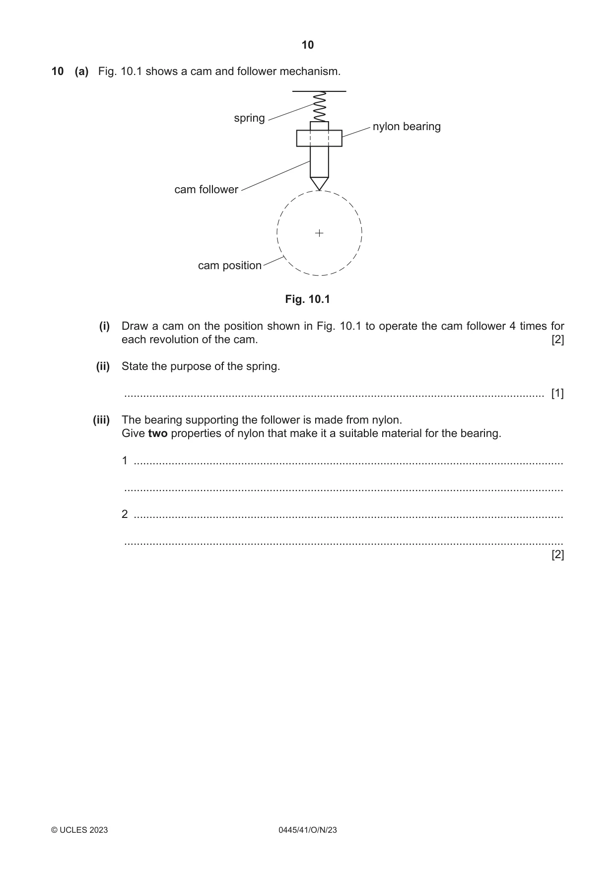
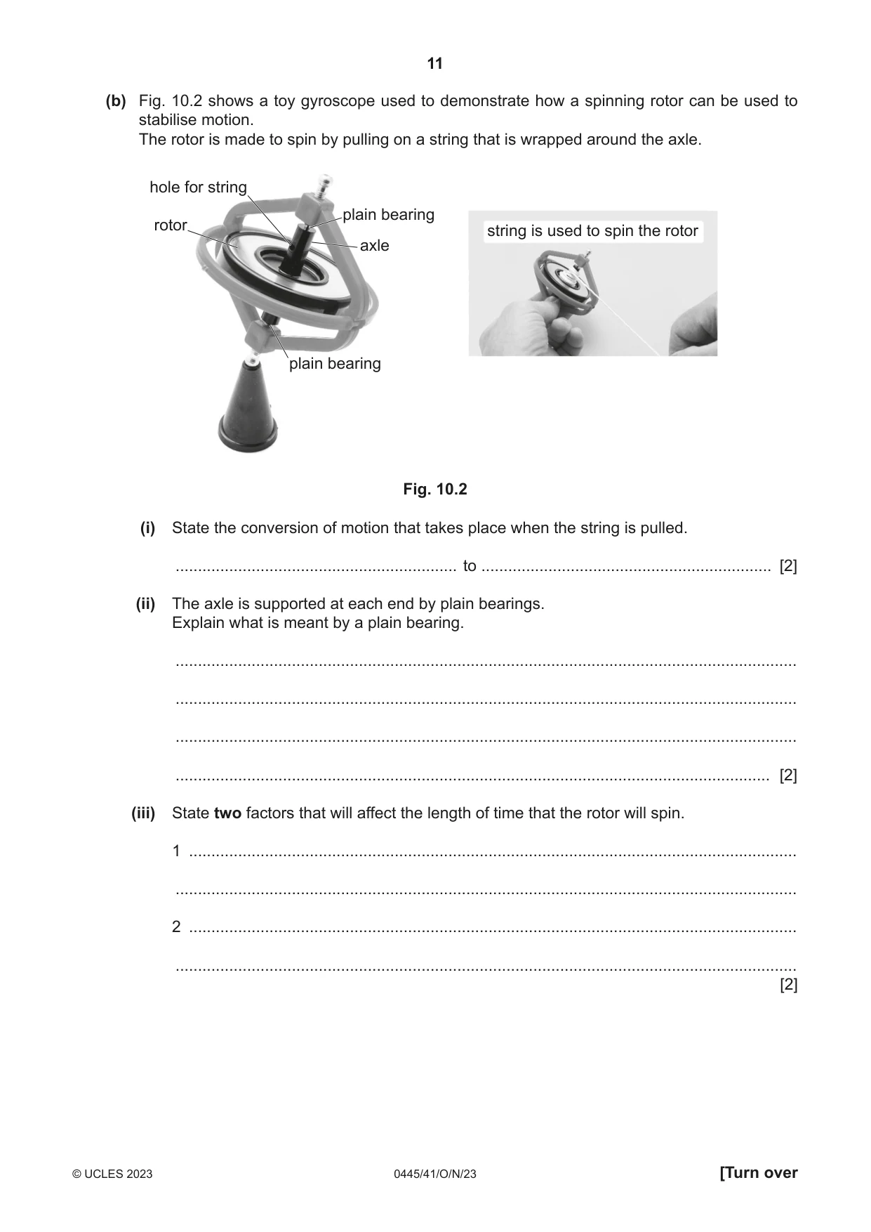
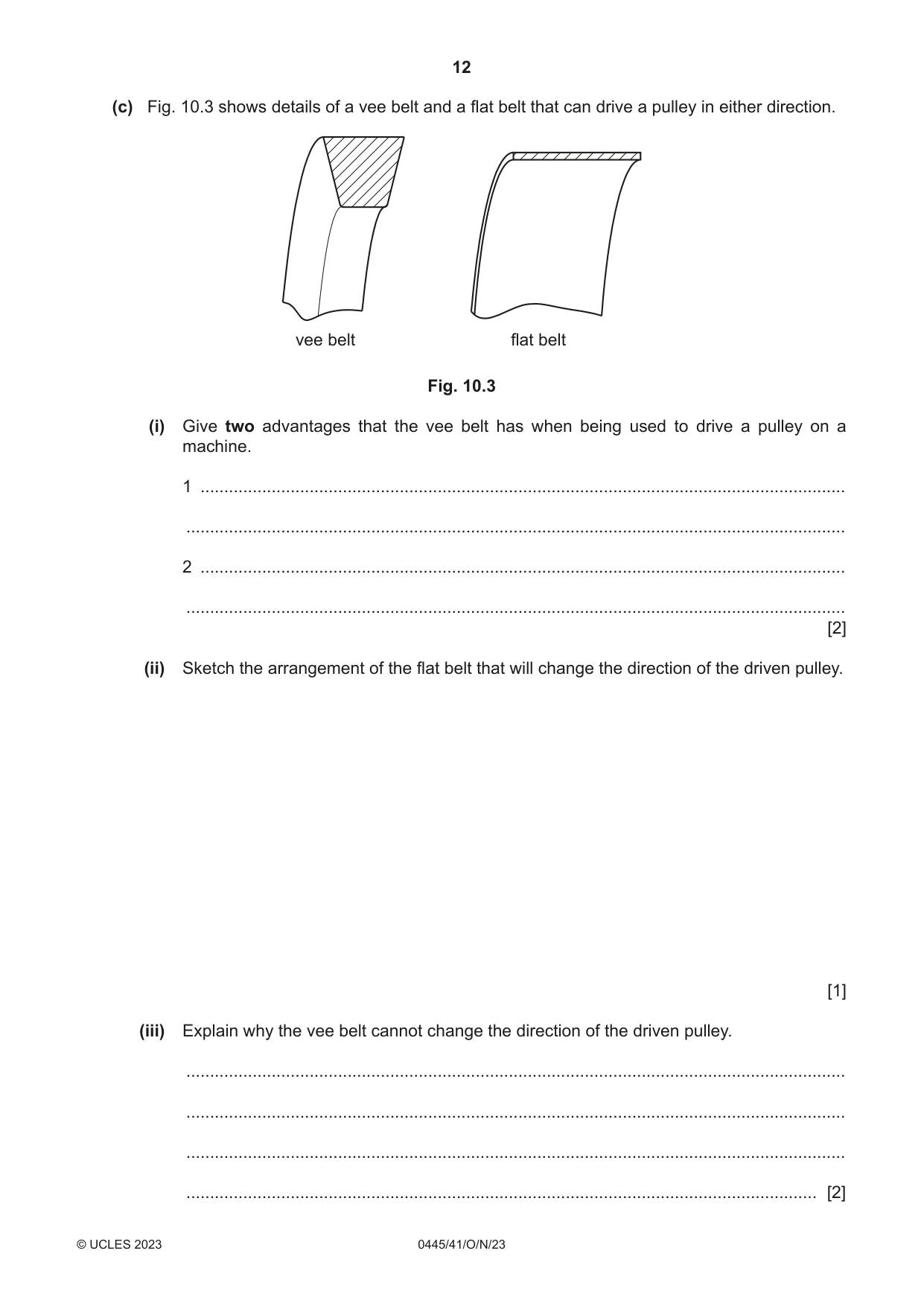
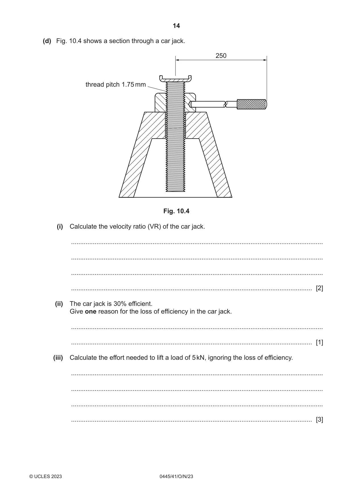
10 (a) Fig. 10.1 shows a cam and follower mechanism. spring nylon bearing cam follower cam position Fig. 10.1 (i) Draw a cam on the position shown in Fig. 10.1 to operate the cam follower 4 times for each revolution of the cam. [2] (ii) State the purpose of the spring. ..................................................................................................................................... [1] (iii) The bearing supporting the follower is made from nylon. Give two properties of nylon that make it a suitable material for the bearing. 1 ........................................................................................................................................ ........................................................................................................................................... 2 ........................................................................................................................................ ........................................................................................................................................... [2] (b) Fig. 10.2 shows a toy gyroscope used to demonstrate how a spinning rotor can be used to stabilise motion. The rotor is made to spin by pulling on a string that is wrapped around the axle. hole for string plain bearing rotor string is used to spin the rotor axle plain bearing Fig. 10.2 (i) State the conversion of motion that takes place when the string is pulled. ............................................................... to ................................................................. [2] (ii) The axle is supported at each end by plain bearings. Explain what is meant by a plain bearing. ........................................................................................................................................... ........................................................................................................................................... ........................................................................................................................................... ..................................................................................................................................... [2] (iii) State two factors that will affect the length of time that the rotor will spin. 1 ........................................................................................................................................ ........................................................................................................................................... 2 ........................................................................................................................................ ........................................................................................................................................... [2] (c) Fig. 10.3 shows details of a vee belt and a flat belt that can drive a pulley in either direction. vee belt flat belt Fig. 10.3 (i) Give two advantages that the vee belt has when being used to drive a pulley on a machine. 1 ........................................................................................................................................ ........................................................................................................................................... 2 ........................................................................................................................................ ........................................................................................................................................... [2] (ii) Sketch the arrangement of the flat belt that will change the direction of the driven pulley. [1] (iii) Explain why the vee belt cannot change the direction of the driven pulley. ........................................................................................................................................... ........................................................................................................................................... ........................................................................................................................................... ..................................................................................................................................... [2] (iv) Use sketches and notes to show a method of tensioning a vee belt without changing the position of the pulleys. [3] (d) Fig. 10.4 shows a section through a car jack. 250 thread pitch 1.75 mm Fig. 10.4 (i) Calculate the velocity ratio (VR) of the car jack. ........................................................................................................................................... ........................................................................................................................................... ........................................................................................................................................... ..................................................................................................................................... [2] (ii) The car jack is 30% efficient. Give one reason for the loss of efficiency in the car jack. ........................................................................................................................................... ..................................................................................................................................... [1] (iii) Calculate the effort needed to lift a load of 5 kN, ignoring the loss of efficiency. ........................................................................................................................................... ........................................................................................................................................... ........................................................................................................................................... ..................................................................................................................................... [3]
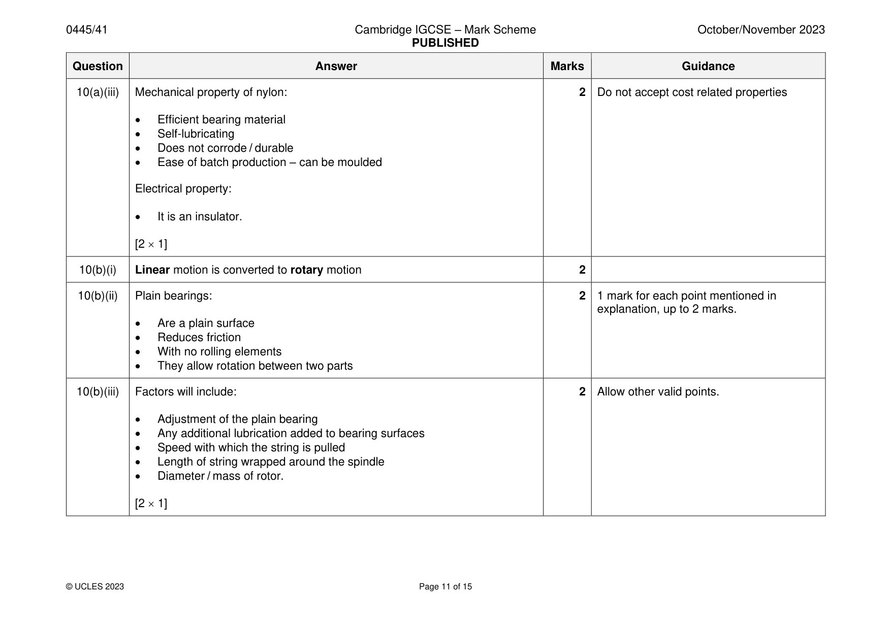
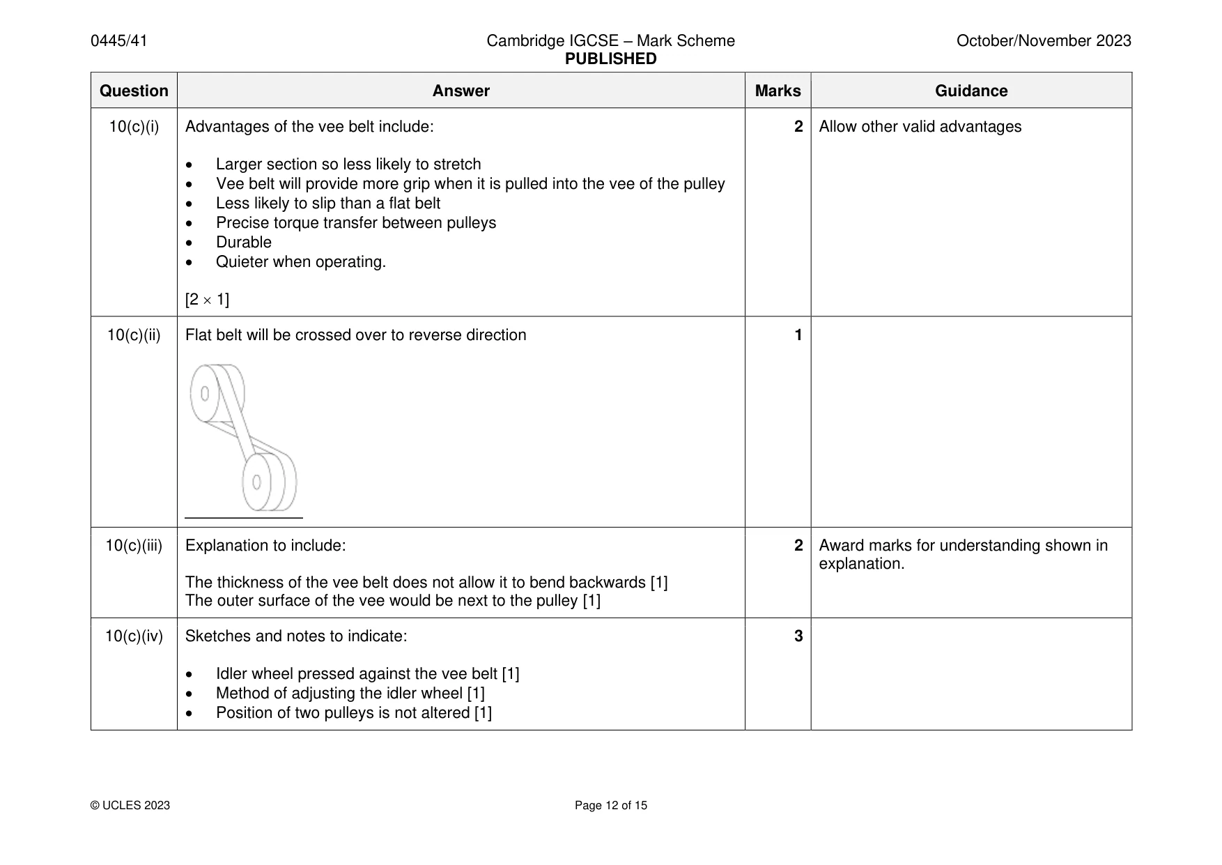
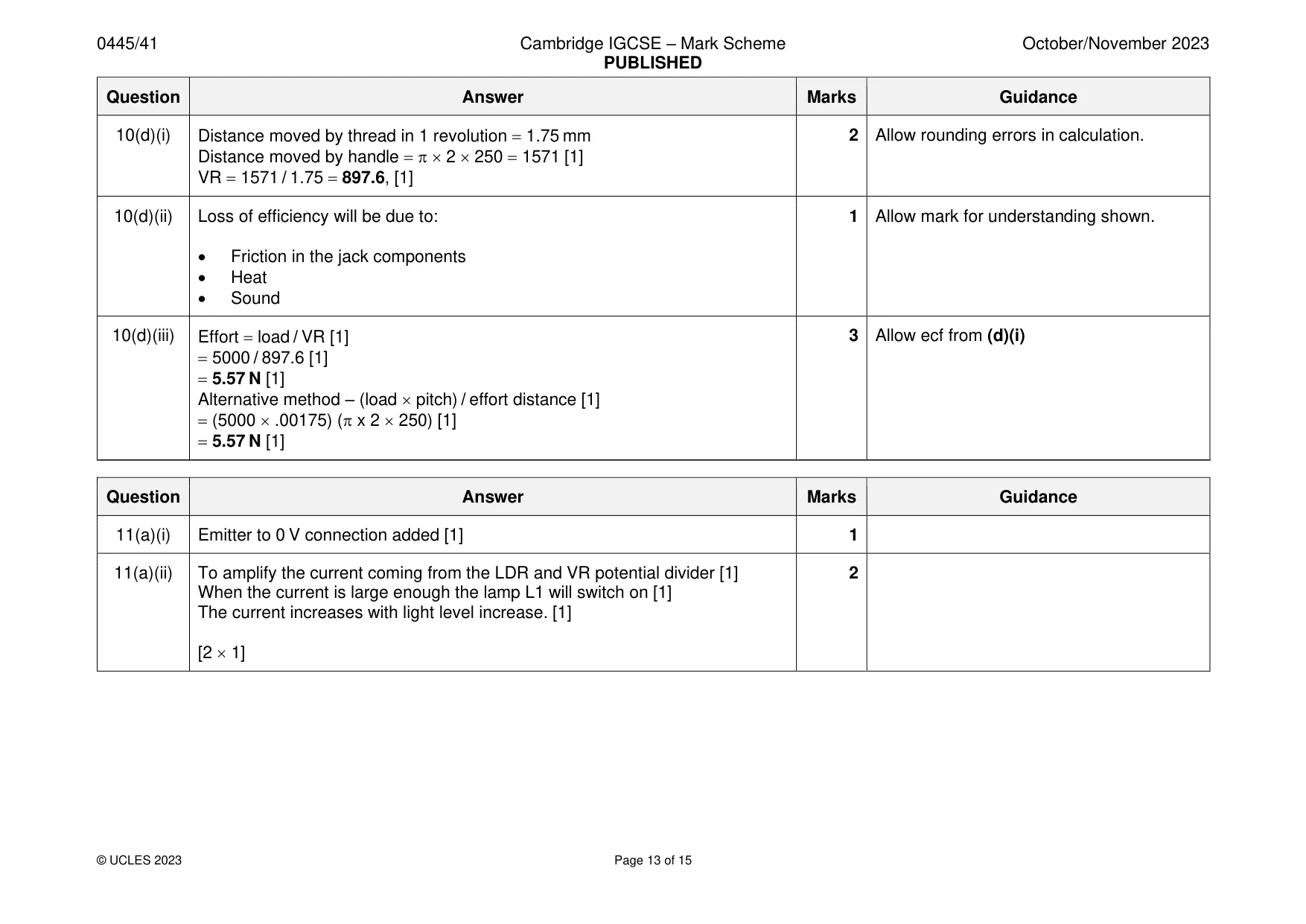
Mark scheme: 10(a)(i) 2 Square cam drawn [1] suitable proportions [1] 10(a)(ii) The spring ensures that the follower is always touching the cam. 1 Allow mark for understanding shown. 10(a)(iii) Mechanical property of nylon: 2 Do not accept cost related properties • Efficient bearing material • Self-lubricating • Does not corrode / durable • Ease of batch production – can be moulded Electrical property: • It is an insulator. [2 1] 10(b)(i) Linear motion is converted to rotary motion 2 10(b)(ii) Plain bearings: 2 1 mark for each point mentioned in explanation, up to 2 marks. • Are a plain surface • Reduces friction • With no rolling elements • They allow rotation between two parts 10(b)(iii) Factors will include: 2 Allow other valid points. • Adjustment of the plain bearing • Any additional lubrication added to bearing surfaces • Speed with which the string is pulled • Length of string wrapped around the spindle • Diameter / mass of rotor. [2 1] 10(c)(i) Advantages of the vee belt include: 2 Allow other valid advantages • Larger section so less likely to stretch • Vee belt will provide more grip when it is pulled into the vee of the pulley • Less likely to slip than a flat belt • Precise torque transfer between pulleys • Durable • Quieter when operating. [2 1] 10(c)(ii) Flat belt will be crossed over to reverse direction 1 10(c)(iii) Explanation to include: 2 Award marks for understanding shown in explanation. The thickness of the vee belt does not allow it to bend backwards [1] The outer surface of the vee would be next to the pulley [1] 10(c)(iv) Sketches and notes to indicate: 3 • Idler wheel pressed against the vee belt [1] • Method of adjusting the idler wheel [1] • Position of two pulleys is not altered [1] 10(d)(i) Distance moved by thread in 1 revolution = 1.75 mm 2 Allow rounding errors in calculation. Distance moved by handle = 2 250 = 1571 [1] VR = 1571 / 1.75 = 897.6, [1] 10(d)(ii) Loss of efficiency will be due to: 1 Allow mark for understanding shown. • Friction in the jack components • Heat • Sound 10(d)(iii) Effort = load / VR [1] 3 Allow ecf from (d)(i) = 5000 / 897.6 [1] = 5.57 N [1] Alternative method – (load pitch) / effort distance [1] = (5000 .00175) ( x 2 250) [1] = 5.57 N [1]
Q11 · An incomplete circuit for a transistor amplifier
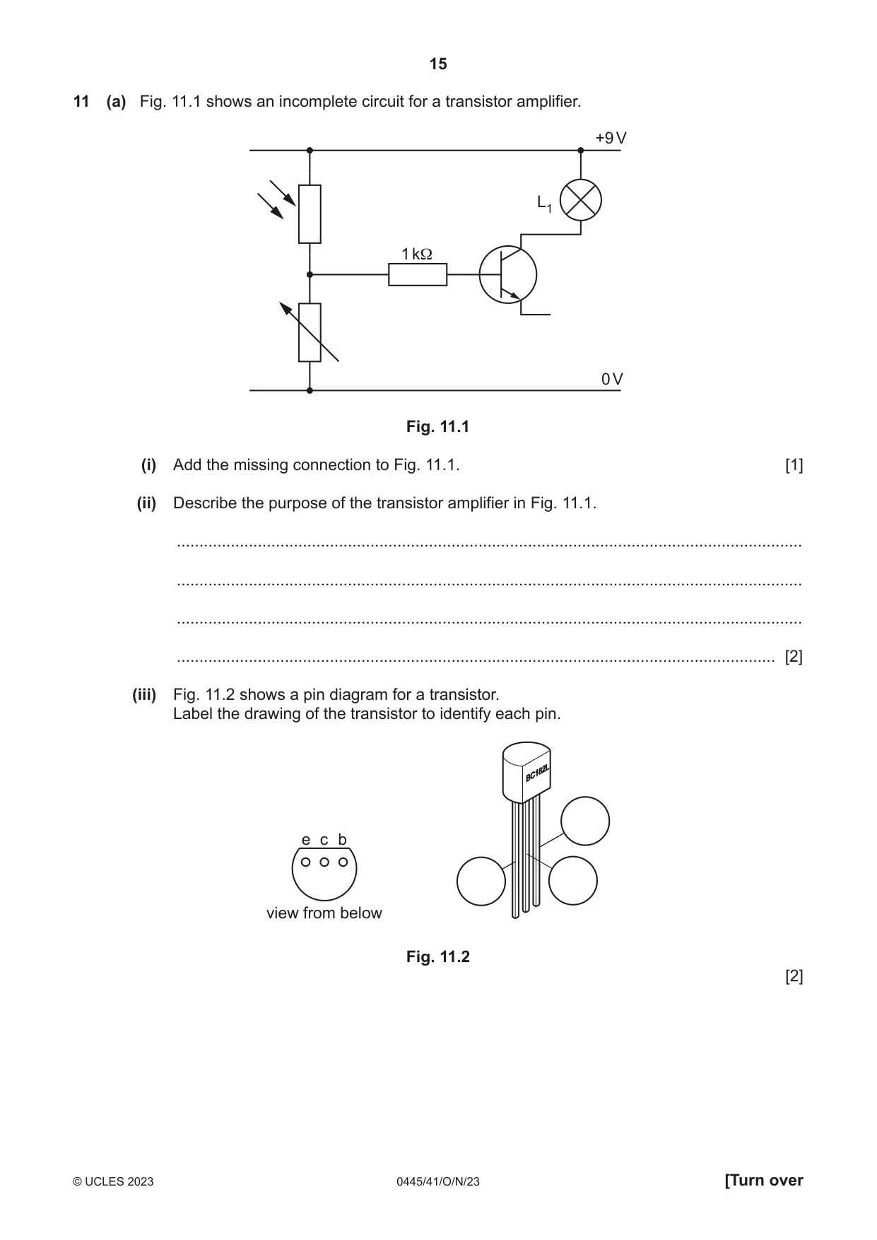
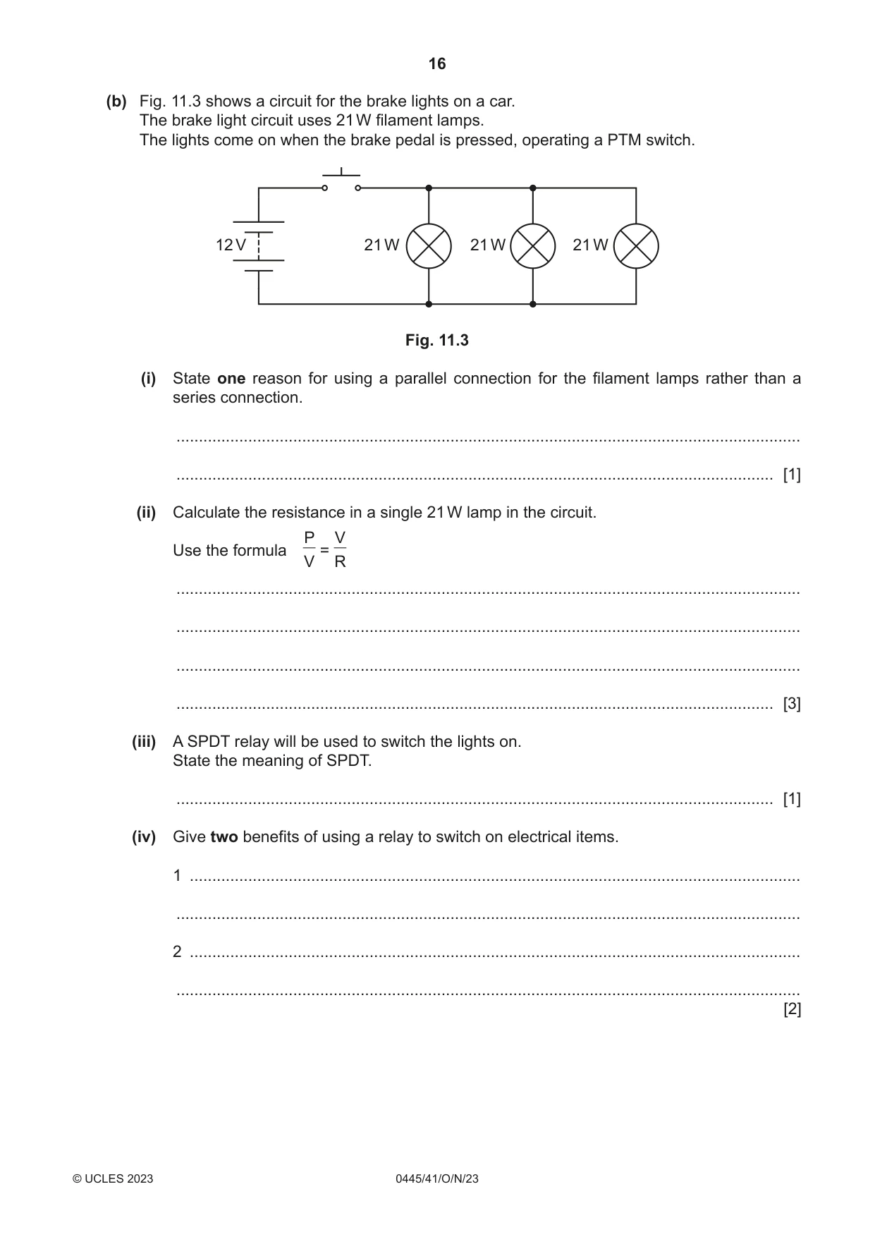
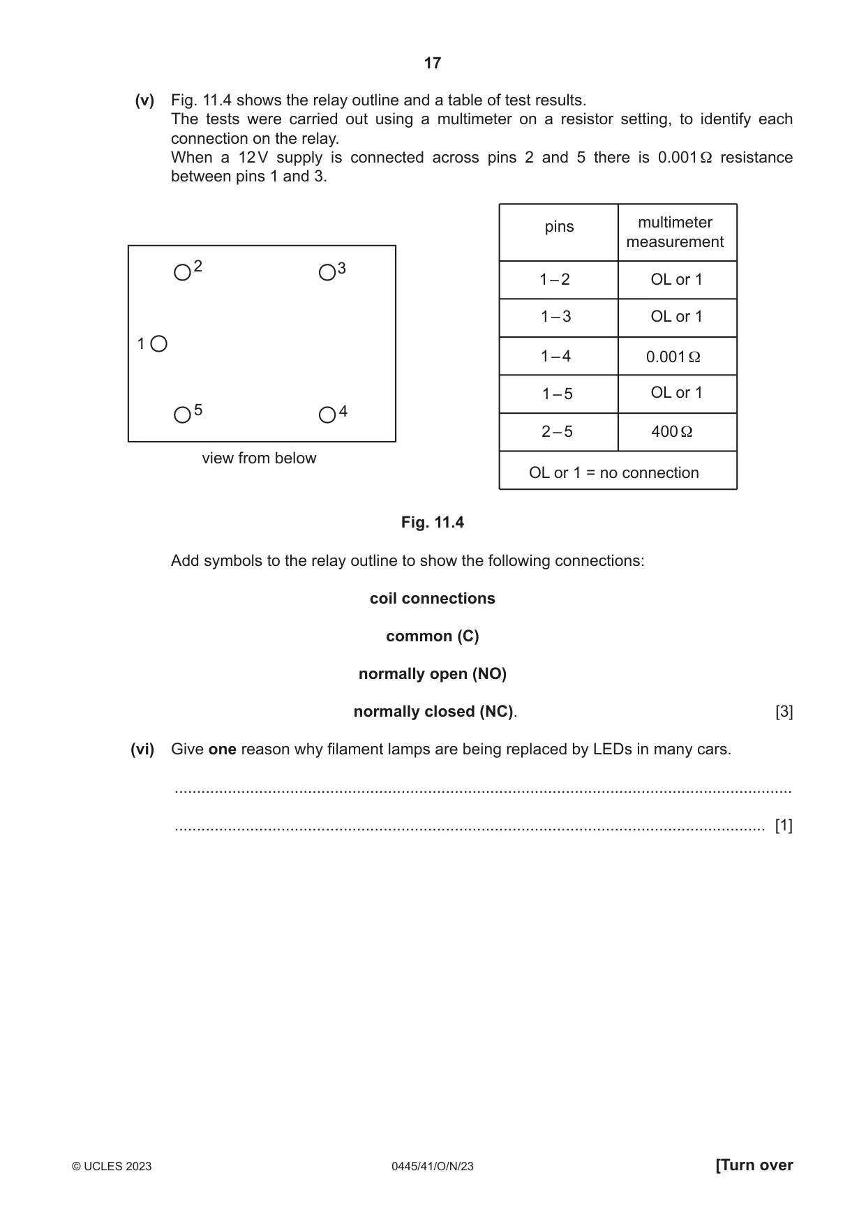
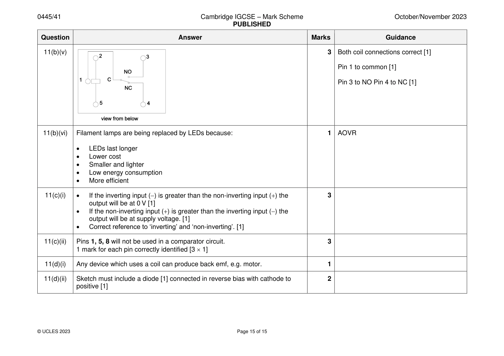
11 (a) Fig. 11.1 shows an incomplete circuit for a transistor amplifier. +9 V L1 1 kΩ 0 V Fig. 11.1 (i) Add the missing connection to Fig. 11.1. [1] (ii) Describe the purpose of the transistor amplifier in Fig. 11.1. ........................................................................................................................................... ........................................................................................................................................... ........................................................................................................................................... ..................................................................................................................................... [2] (iii) Fig. 11.2 shows a pin diagram for a transistor. Label the drawing of the transistor to identify each pin. e c b view from below Fig. 11.2 [2] (b) Fig. 11.3 shows a circuit for the brake lights on a car. The brake light circuit uses 21 W filament lamps. The lights come on when the brake pedal is pressed, operating a PTM switch. 12 V 21 W 21 W 21 W Fig. 11.3 (i) State one reason for using a parallel connection for the filament lamps rather than a series connection. ........................................................................................................................................... ..................................................................................................................................... [1] (ii) Calculate the resistance in a single 21 W lamp in the circuit. P V Use the formula = V R ........................................................................................................................................... ........................................................................................................................................... ........................................................................................................................................... ..................................................................................................................................... [3] (iii) A SPDT relay will be used to switch the lights on. State the meaning of SPDT. ..................................................................................................................................... [1] (iv) Give two benefits of using a relay to switch on electrical items. 1 ........................................................................................................................................ ........................................................................................................................................... 2 ........................................................................................................................................ ........................................................................................................................................... [2] (v) Fig. 11.4 shows the relay outline and a table of test results. The tests were carried out using a multimeter on a resistor setting, to identify each connection on the relay. When a 12 V supply is connected across pins 2 and 5 there is 0.001 Ω resistance between pins 1 and 3. pins multimeter measurement 2 3 1 – 2 OL or 1 1 – 3 OL or 1 1 1 – 4 0.001 Ω 1 – 5 OL or 1 5 4 2 – 5 400 Ω view from below OL or 1 = no connection Fig. 11.4 Add symbols to the relay outline to show the following connections: coil connections common (C) normally open (NO) normally closed (NC). [3] (vi) Give one reason why filament lamps are being replaced by LEDs in many cars. ........................................................................................................................................... ..................................................................................................................................... [1]
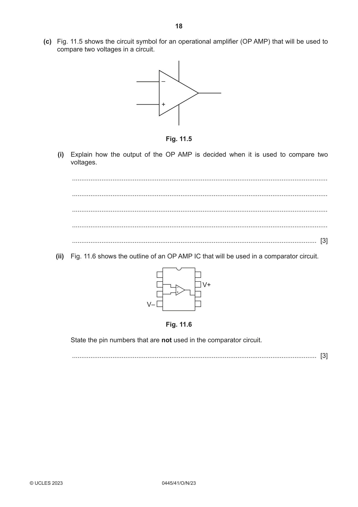
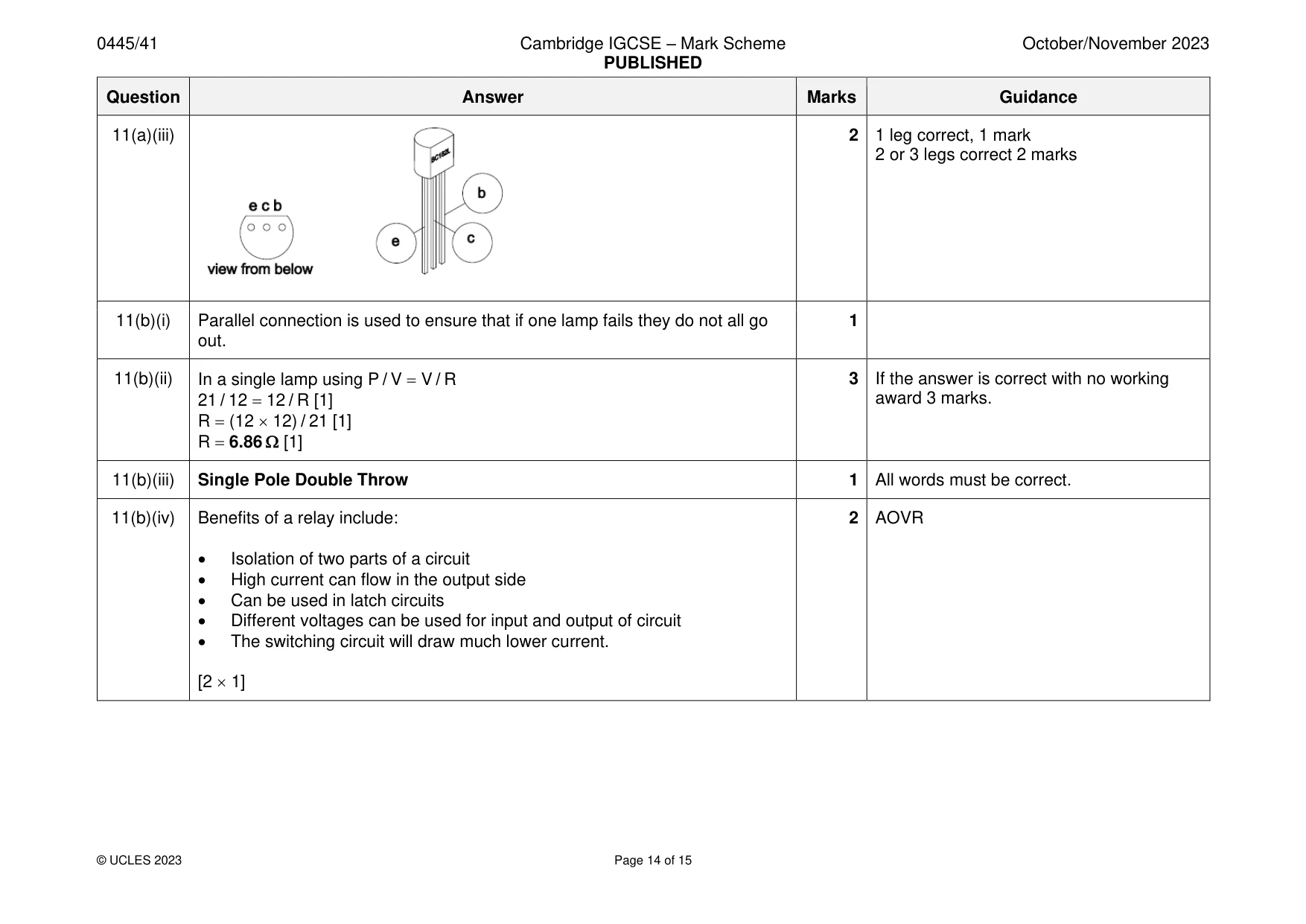
Mark scheme: 11(a)(i) Emitter to 0 V connection added [1] 1 11(a)(ii) To amplify the current coming from the LDR and VR potential divider [1] 2 When the current is large enough the lamp L1 will switch on [1] The current increases with light level increase. [1] [2 1] 11(a)(iii) 2 1 leg correct, 1 mark 2 or 3 legs correct 2 marks 11(b)(i) Parallel connection is used to ensure that if one lamp fails they do not all go 1 out. 11(b)(ii) In a single lamp using P / V = V / R 3 If the answer is correct with no working 21 / 12 = 12 / R [1] award 3 marks. R = (12 12) / 21 [1] R = 6.86 [1] 11(b)(iii) Single Pole Double Throw 1 All words must be correct. 11(b)(iv) Benefits of a relay include: 2 AOVR • Isolation of two parts of a circuit • High current can flow in the output side • Can be used in latch circuits • Different voltages can be used for input and output of circuit • The switching circuit will draw much lower current. [2 1] 11(b)(v) 3 Both coil connections correct [1] Pin 1 to common [1] Pin 3 to NO Pin 4 to NC [1] 11(b)(vi) Filament lamps are being replaced by LEDs because: 1 AOVR • LEDs last longer • Lower cost • Smaller and lighter • Low energy consumption • More efficient 11(c)(i) • If the inverting input (−) is greater than the non-inverting input (+) the 3 output will be at 0 V [1] • If the non-inverting input (+) is greater than the inverting input (−) the output will be at supply voltage. [1] • Correct reference to ‘inverting’ and ‘non-inverting’. [1] 11(c)(ii) Pins 1, 5, 8 will not be used in a comparator circuit. 3 1 mark for each pin correctly identified [3 1] 11(d)(i) Any device which uses a coil can produce back emf, e.g. motor. 1 11(d)(ii) Sketch must include a diode [1] connected in reverse bias with cathode to 2 positive [1]
What was in this paper
The subtopics covered by these 11 questions, and how many questions each got. Open one in a new tab to see every Cambridge question on it.
What you needed in this session
Cambridge’s own grade thresholds for 2023 Oct/Nov, Paper 4 · Variant 1. A higher threshold means an easier paper — the bar moves with how the cohort did.