Cambridge IGCSE Design and Technology 0445 — 2024 Oct/Nov Paper 4 · Variant 1
0445/41/O/N/24 · 11 questions · 50 marks · 60 min
The question paper and its mark scheme, free to read here and free to download. This is Cambridge’s own paper, exactly as it was sat.
Question paper20 pages
Mark scheme12 pages
Answers below. Sit the paper first if you are practising.
Questions as text
Q1 · A wooden door frame ready to be placed in a building
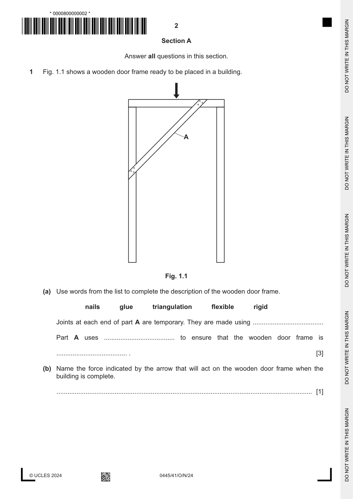
1 Fig. 1.1 shows a wooden door frame ready to be placed in a building. A Fig. 1.1 (a) Use words from the list to complete the description of the wooden door frame. nails glue triangulation flexible rigid Joints at each end of part A are temporary. They are made using ....................................... Part A uses ....................................... to ensure that the wooden door frame is ....................................... . [3] (b) Name the force indicated by the arrow that will act on the wooden door frame when the building is complete. ............................................................................................................................................. [1]
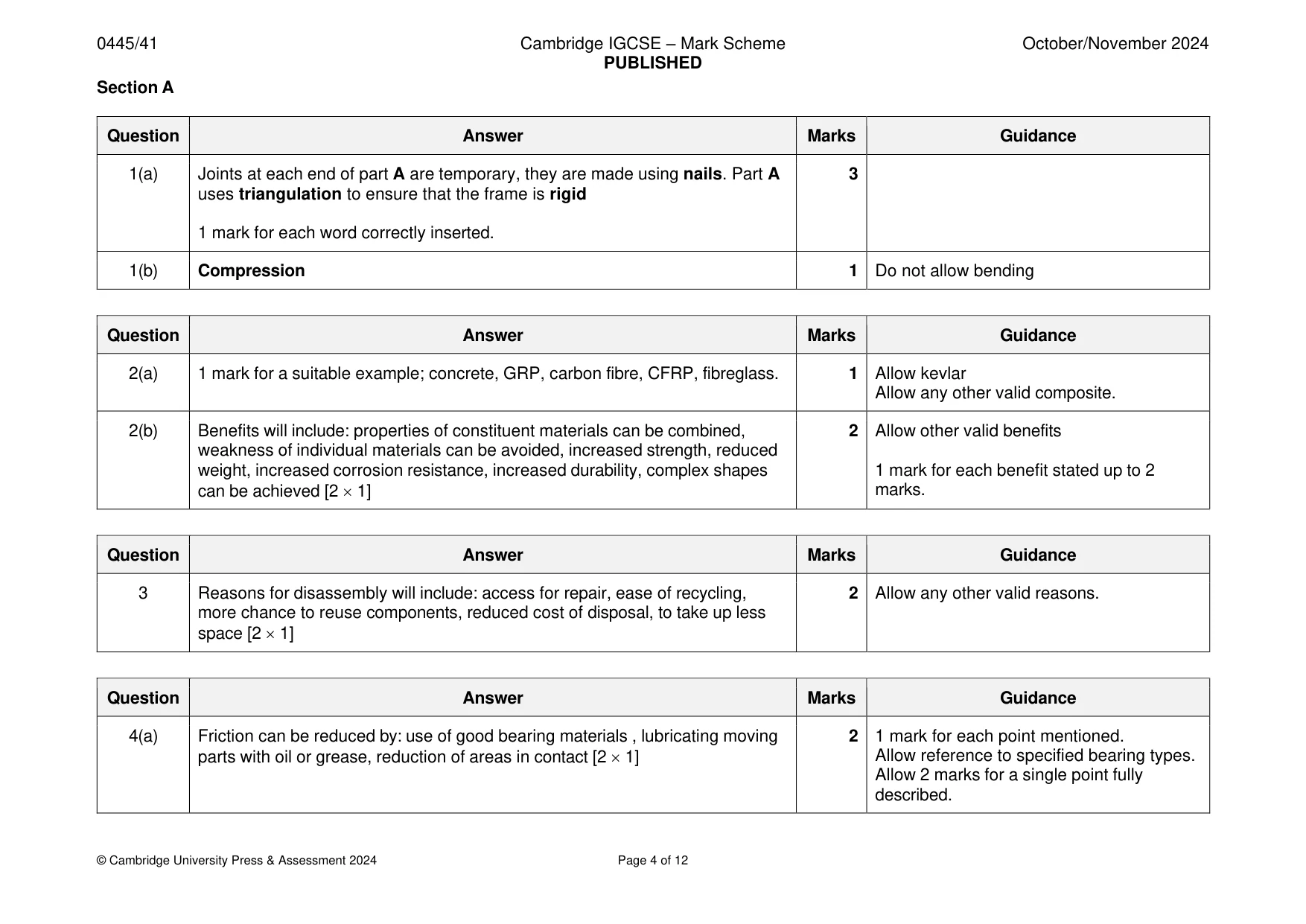
Mark scheme: Question Answer Marks Guidance 1(a) Joints at each end of part A are temporary, they are made using nails. Part A 3 uses triangulation to ensure that the frame is rigid 1 mark for each word correctly inserted. 1(b) Compression 1 Do not allow bending
Q2 · Composite materials can be used in the construction of beams
2 Composite materials can be used in the construction of beams. (a) Give one example of a composite material. ............................................................................................................................................. [1] (b) State two benefits of using composite materials. 1 ................................................................................................................................................ 2 ................................................................................................................................................ [2]
Mark scheme: 2(a) 1 mark for a suitable example; concrete, GRP, carbon fibre, CFRP, fibreglass. 1 Allow kevlar Allow any other valid composite. 2(b) Benefits will include: properties of constituent materials can be combined, 2 Allow other valid benefits weakness of individual materials can be avoided, increased strength, reduced weight, increased corrosion resistance, increased durability, complex shapes 1 mark for each benefit stated up to 2 can be achieved [2 1] marks.
Q3 · Give two reasons why products that can be disassembled are good for the environment
3 Give two reasons why products that can be disassembled are good for the environment. 1 ....................................................................................................................................................... 2 ....................................................................................................................................................... [2]
Mark scheme: 3 Reasons for disassembly will include: access for repair, ease of recycling, 2 Allow any other valid reasons. more chance to reuse components, reduced cost of disposal, to take up less space [2 1]
Q4 · A car handbrake lever
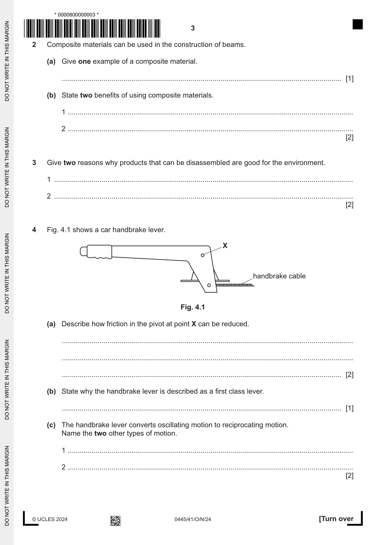
4 Fig. 4.1 shows a car handbrake lever. X handbrake cable Fig. 4.1 (a) Describe how friction in the pivot at point X can be reduced. ................................................................................................................................................... ................................................................................................................................................... ............................................................................................................................................. [2] (b) State why the handbrake lever is described as a first class lever. ............................................................................................................................................. [1] (c) The handbrake lever converts oscillating motion to reciprocating motion. Name the two other types of motion. 1 ................................................................................................................................................ 2 ................................................................................................................................................ [2]
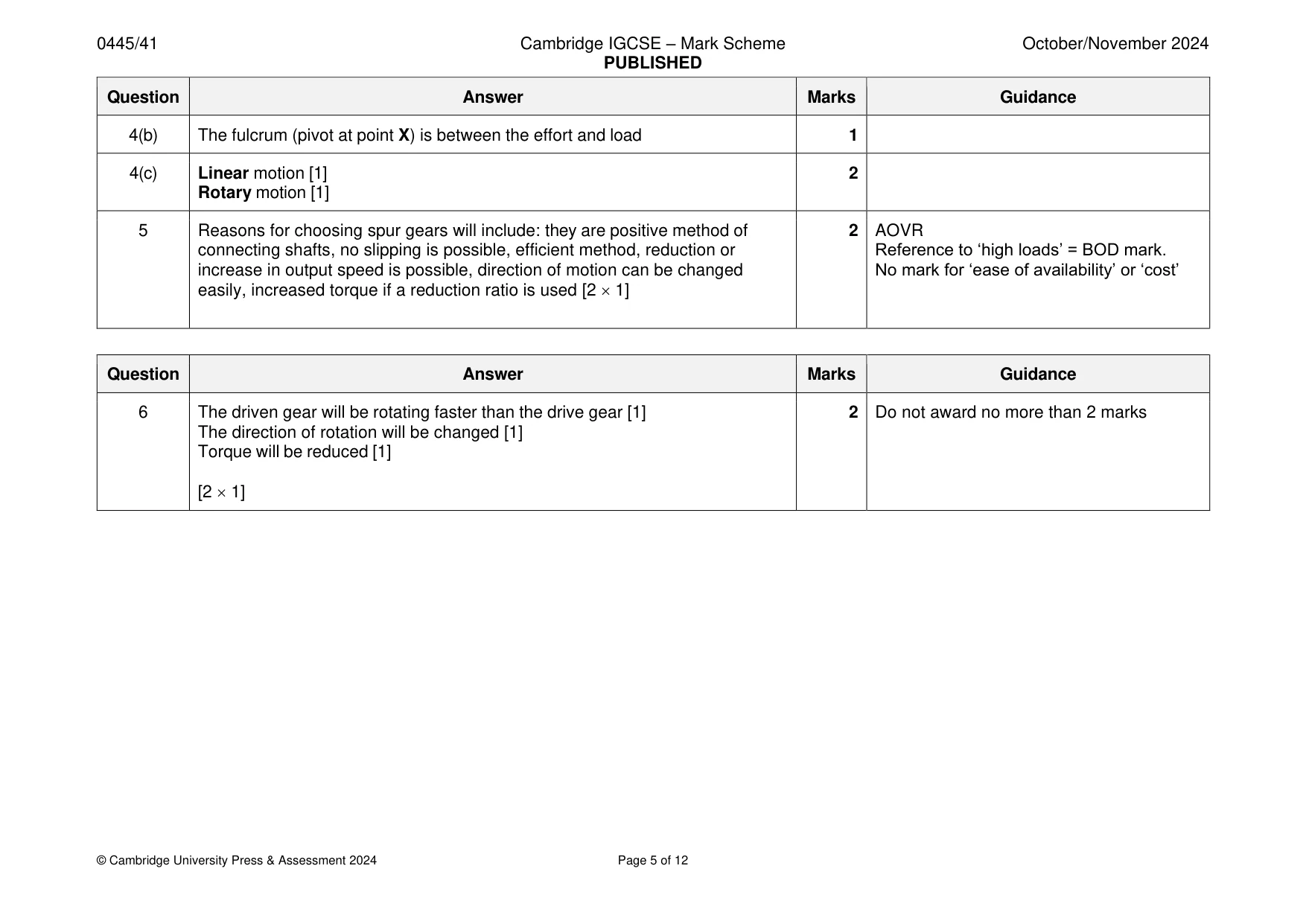
Mark scheme: 4(a) Friction can be reduced by: use of good bearing materials , lubricating moving 2 1 mark for each point mentioned. parts with oil or grease, reduction of areas in contact [2 1] Allow reference to specified bearing types. Allow 2 marks for a single point fully described. 4(b) The fulcrum (pivot at point X) is between the effort and load 1 4(c) Linear motion [1] 2 Rotary motion [1]
Q5 · Give two reasons for choosing spur gears to drive a mechanism
5 Give two reasons for choosing spur gears to drive a mechanism. 1 ....................................................................................................................................................... 2 ....................................................................................................................................................... [2]
Mark scheme: 5 Reasons for choosing spur gears will include: they are positive method of 2 AOVR connecting shafts, no slipping is possible, efficient method, reduction or Reference to ‘high loads’ = BOD mark. increase in output speed is possible, direction of motion can be changed No mark for ‘ease of availability’ or ‘cost’ easily, increased torque if a reduction ratio is used [2 1]
Question 6
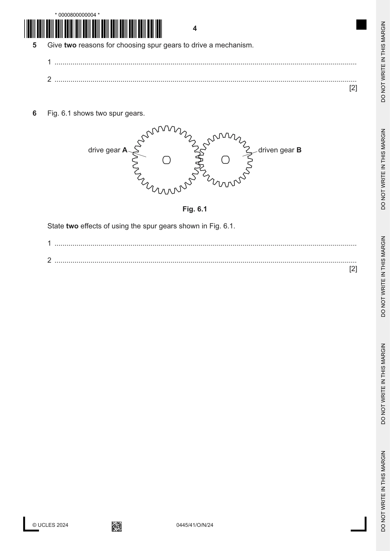
6 Fig. 6.1 shows two spur gears. drive gear A driven gear B Fig. 6.1 State two effects of using the spur gears shown in Fig. 6.1. 1 ....................................................................................................................................................... 2 ....................................................................................................................................................... [2]
Mark scheme: 6 The driven gear will be rotating faster than the drive gear [1] 2 Do not award no more than 2 marks The direction of rotation will be changed [1] Torque will be reduced [1] [2 1]
Q7 · Examples of electronic components and symbols
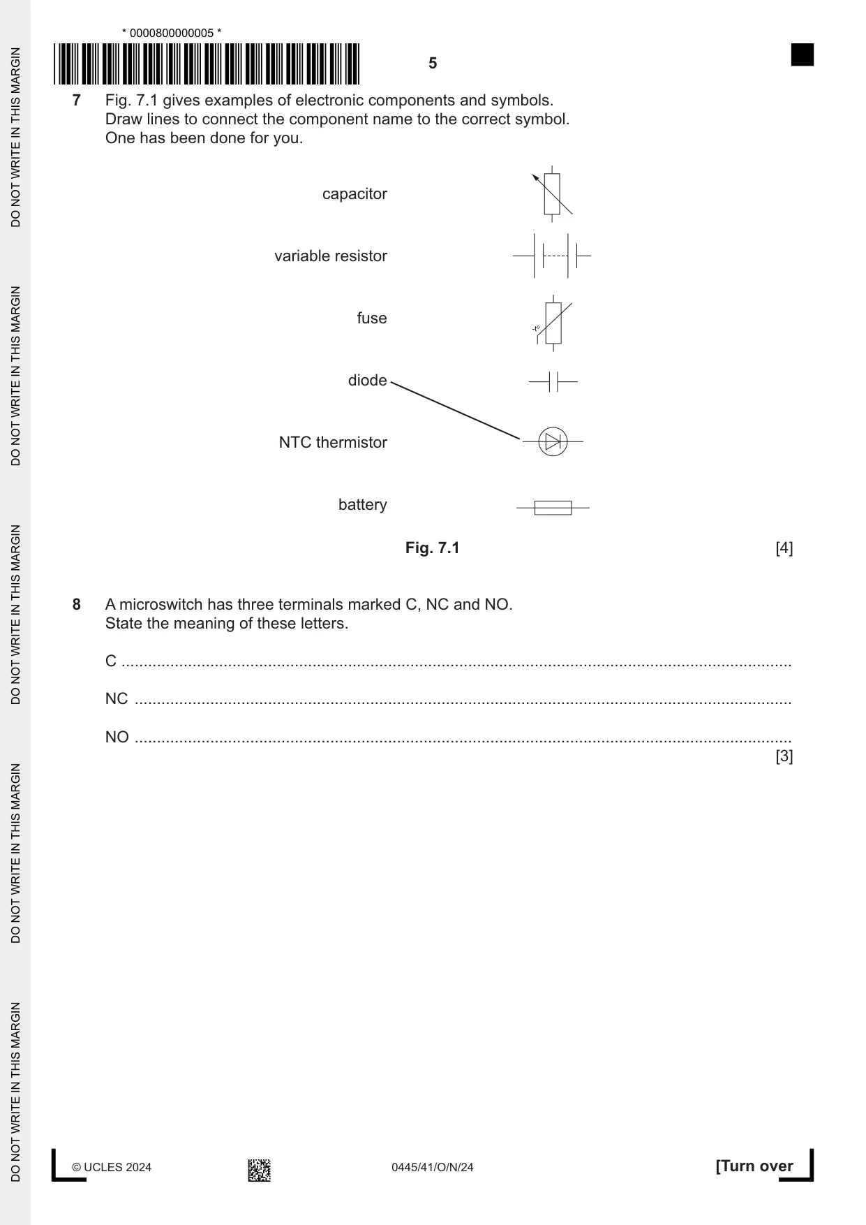
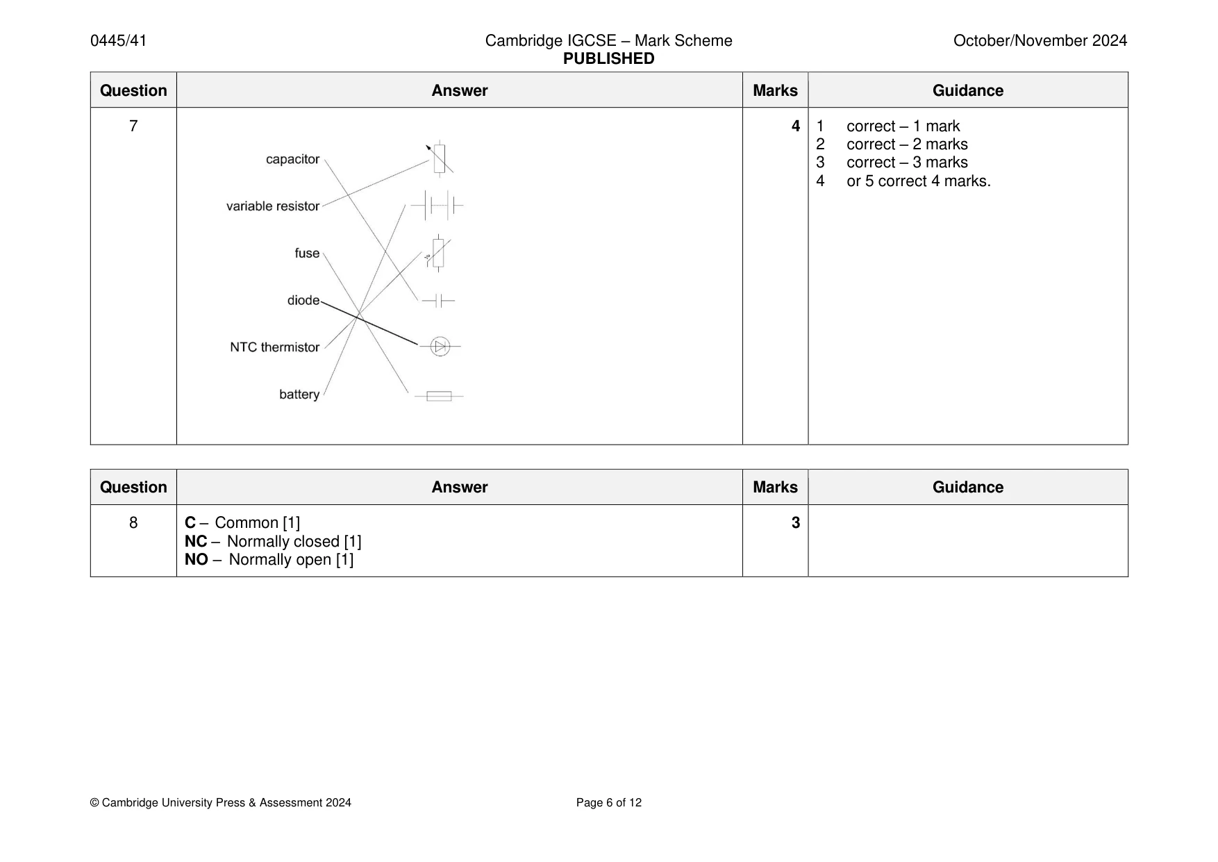
7 Fig. 7.1 gives examples of electronic components and symbols. Draw lines to connect the component name to the correct symbol. One has been done for you. capacitor variable resistor fuse diode NTC thermistor battery Fig. 7.1 [4]
Mark scheme: 7 4 1 correct – 1 mark 2 correct – 2 marks 3 correct – 3 marks 4 or 5 correct 4 marks.
Q8 · A microswitch has three terminals marked C, NC and NO
8 A microswitch has three terminals marked C, NC and NO. State the meaning of these letters. C ....................................................................................................................................................... NC .................................................................................................................................................... NO .................................................................................................................................................... [3]
Mark scheme: 8 C – Common [1] 3 NC – Normally closed [1] NO – Normally open [1] Section B
Q9 · A building with scaffolding in position
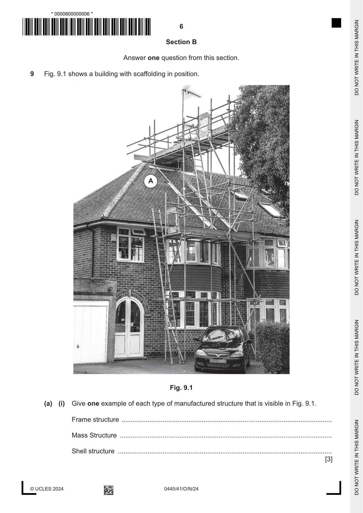
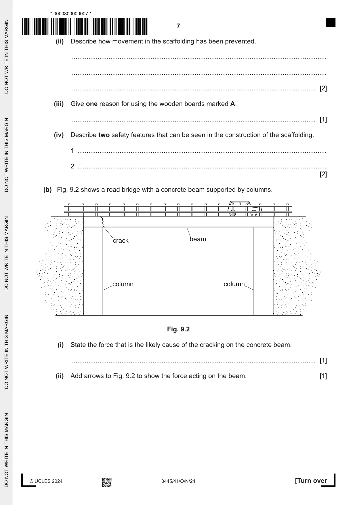
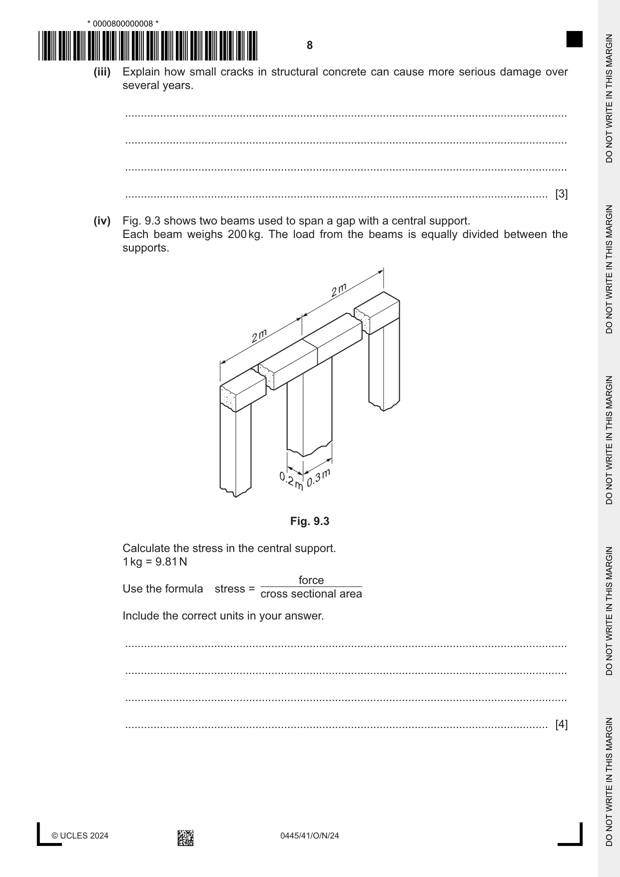
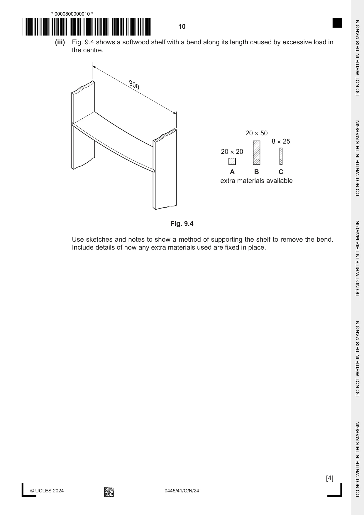
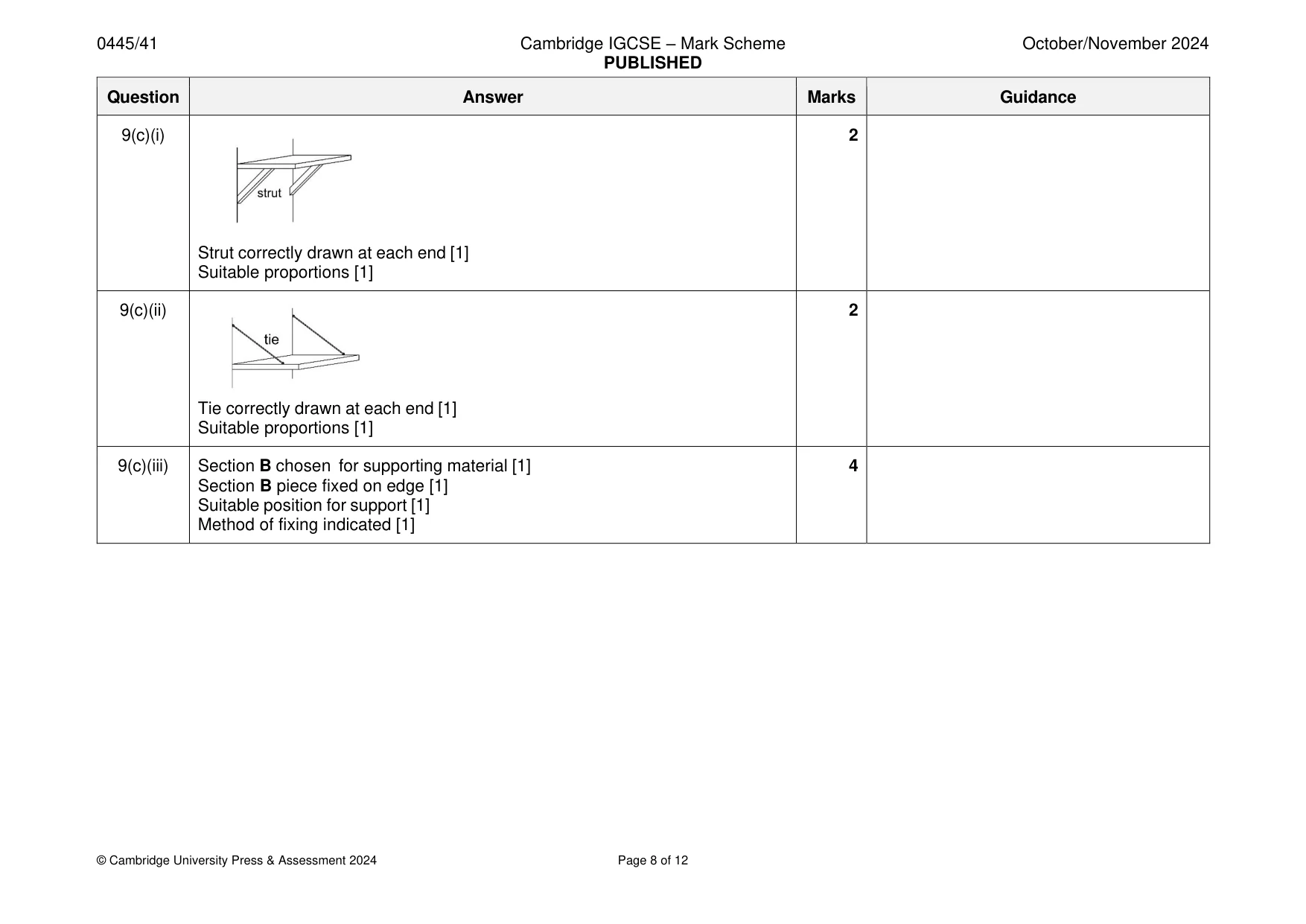
9 Fig. 9.1 shows a building with scaffolding in position. A Fig. 9.1 (a) (i) Give one example of each type of manufactured structure that is visible in Fig. 9.1. Frame structure ................................................................................................................. Mass Structure .................................................................................................................. Shell structure ................................................................................................................... [3] (ii) Describe how movement in the scaffolding has been prevented. ........................................................................................................................................... ........................................................................................................................................... ..................................................................................................................................... [2] (iii) Give one reason for using the wooden boards marked A. ..................................................................................................................................... [1] (iv) Describe two safety features that can be seen in the construction of the scaffolding. 1 ........................................................................................................................................ 2 ........................................................................................................................................ [2] (b) Fig. 9.2 shows a road bridge with a concrete beam supported by columns. crack beam column column Fig. 9.2 (i) State the force that is the likely cause of the cracking on the concrete beam. ..................................................................................................................................... [1] (ii) Add arrows to Fig. 9.2 to show the force acting on the beam. [1] (iii) Explain how small cracks in structural concrete can cause more serious damage over several years. ........................................................................................................................................... ........................................................................................................................................... ........................................................................................................................................... ..................................................................................................................................... [3] (iv) Fig. 9.3 shows two beams used to span a gap with a central support. Each beam weighs 200 kg. The load from the beams is equally divided between the supports. m 2 m 2 m 0.2 0.3 m Fig. 9.3 Calculate the stress in the central support. 1 kg = 9.81 N force Use the formula stress = cross sectional area Include the correct units in your answer. ........................................................................................................................................... ........................................................................................................................................... ........................................................................................................................................... ..................................................................................................................................... [4] (c) Use sketches and notes to show the following structures: (i) A shelf supported at each end by struts. [2] (ii) A shelf supported at each end by ties. [2] (iii) Fig. 9.4 shows a softwood shelf with a bend along its length caused by excessive load in the centre. 900 20 × 50 8 × 25 20 × 20 A B C extra materials available Fig. 9.4 Use sketches and notes to show a method of supporting the shelf to remove the bend. Include details of how any extra materials used are fixed in place. [4]
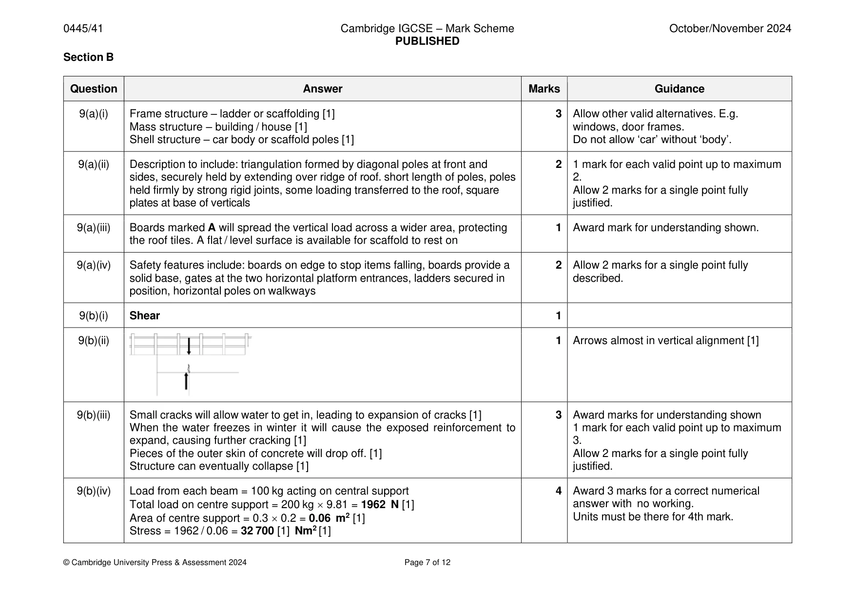
Mark scheme: 9(a)(i) Frame structure – ladder or scaffolding [1] 3 Allow other valid alternatives. E.g. Mass structure – building / house [1] windows, door frames. Shell structure – car body or scaffold poles [1] Do not allow ‘car’ without ‘body’. 9(a)(ii) Description to include: triangulation formed by diagonal poles at front and 2 1 mark for each valid point up to maximum sides, securely held by extending over ridge of roof. short length of poles, poles 2. held firmly by strong rigid joints, some loading transferred to the roof, square Allow 2 marks for a single point fully plates at base of verticals justified. 9(a)(iii) Boards marked A will spread the vertical load across a wider area, protecting 1 Award mark for understanding shown. the roof tiles. A flat / level surface is available for scaffold to rest on 9(a)(iv) Safety features include: boards on edge to stop items falling, boards provide a 2 Allow 2 marks for a single point fully solid base, gates at the two horizontal platform entrances, ladders secured in described. position, horizontal poles on walkways 9(b)(i) Shear 1 9(b)(ii) 1 Arrows almost in vertical alignment [1] 9(b)(iii) Small cracks will allow water to get in, leading to expansion of cracks [1] 3 Award marks for understanding shown When the water freezes in winter it will cause the exposed reinforcement to 1 mark for each valid point up to maximum expand, causing further cracking [1] 3. Pieces of the outer skin of concrete will drop off. [1] Allow 2 marks for a single point fully Structure can eventually collapse [1] justified. 9(b)(iv) Load from each beam = 100 kg acting on central support 4 Award 3 marks for a correct numerical Total load on centre support = 200 kg 9.81 = 1962 N [1] answer with no working. Area of centre support = 0.3 0.2 = 0.06 m2 [1] Units must be there for 4th mark. Stress = 1962 / 0.06 = 32 700 [1] Nm2 [1] 9(c)(i) 2 Strut correctly drawn at each end [1] Suitable proportions [1] 9(c)(ii) 2 Tie correctly drawn at each end [1] Suitable proportions [1] 9(c)(iii) Section B chosen for supporting material [1] 4 Section B piece fixed on edge [1] Suitable position for support [1] Method of fixing indicated [1]
Q10 · A mechanism used to raise or lower a gate on a waterway
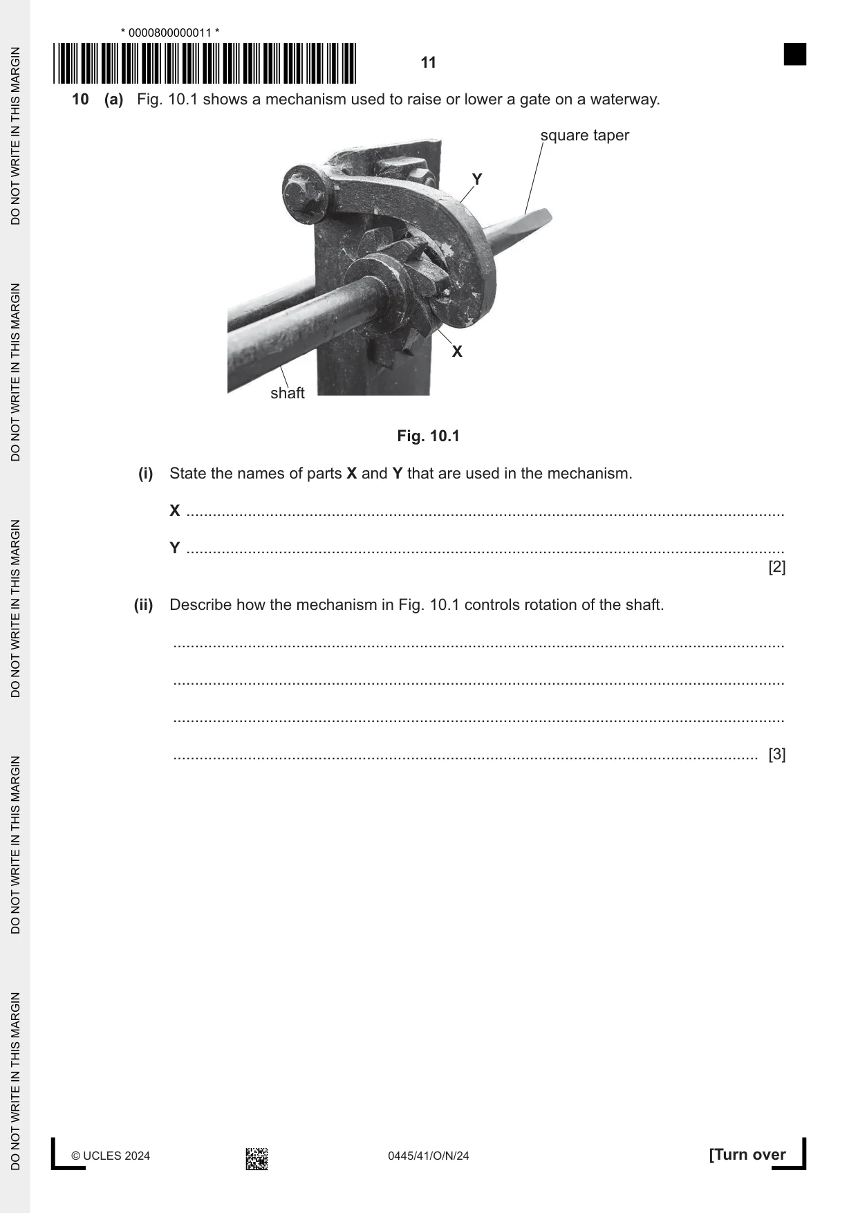
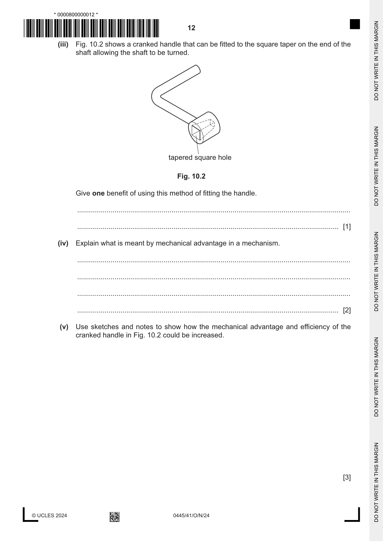
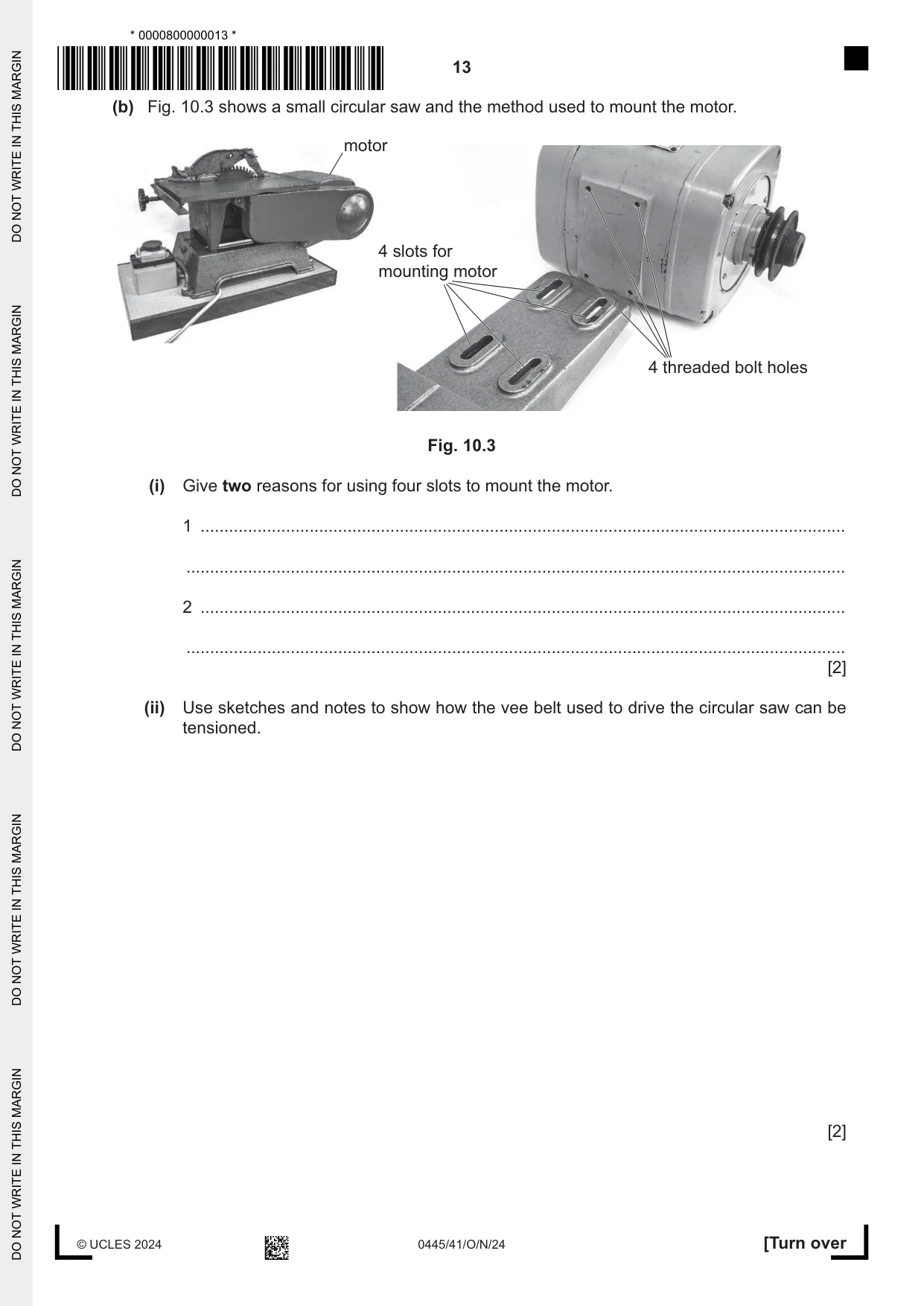
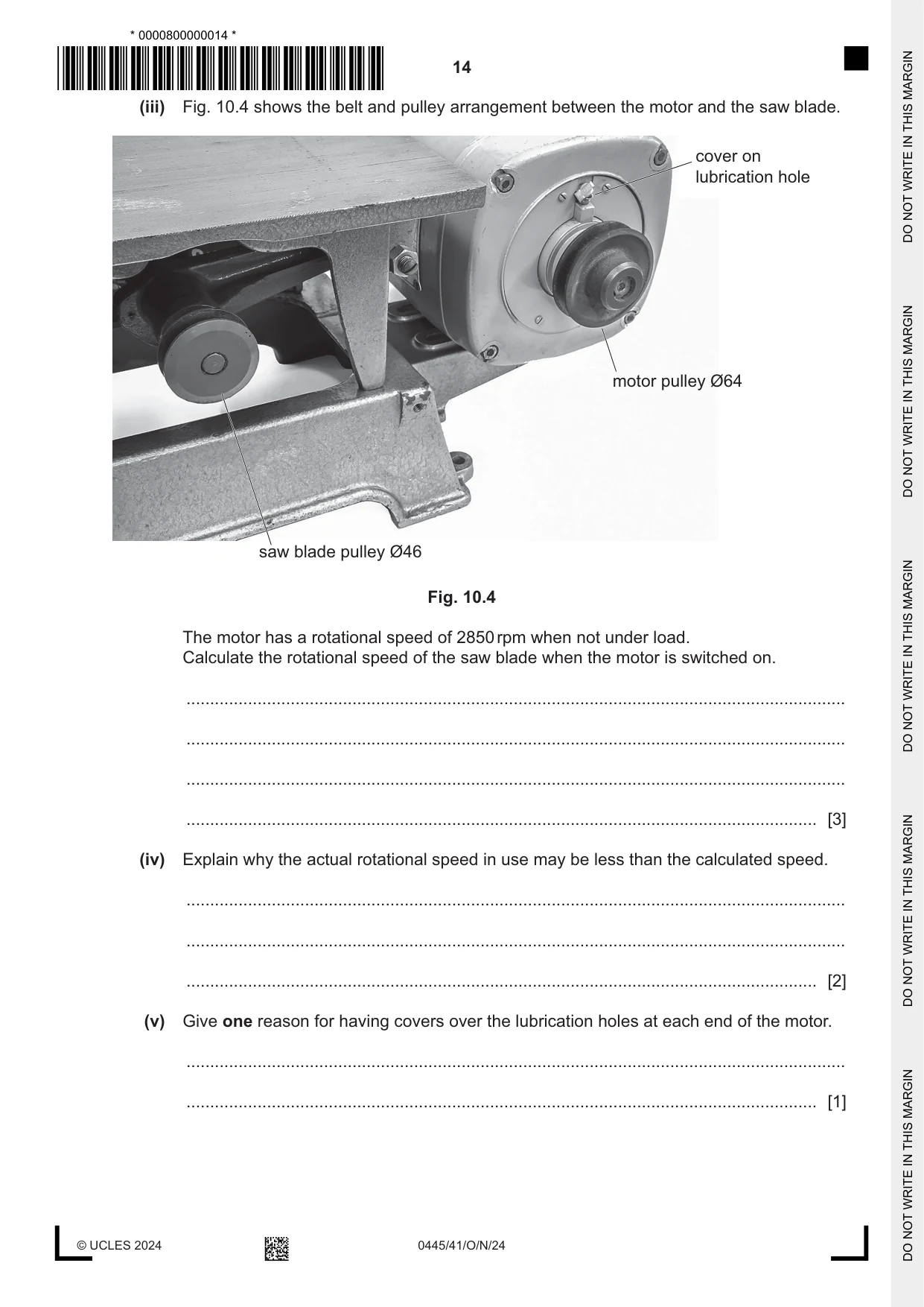
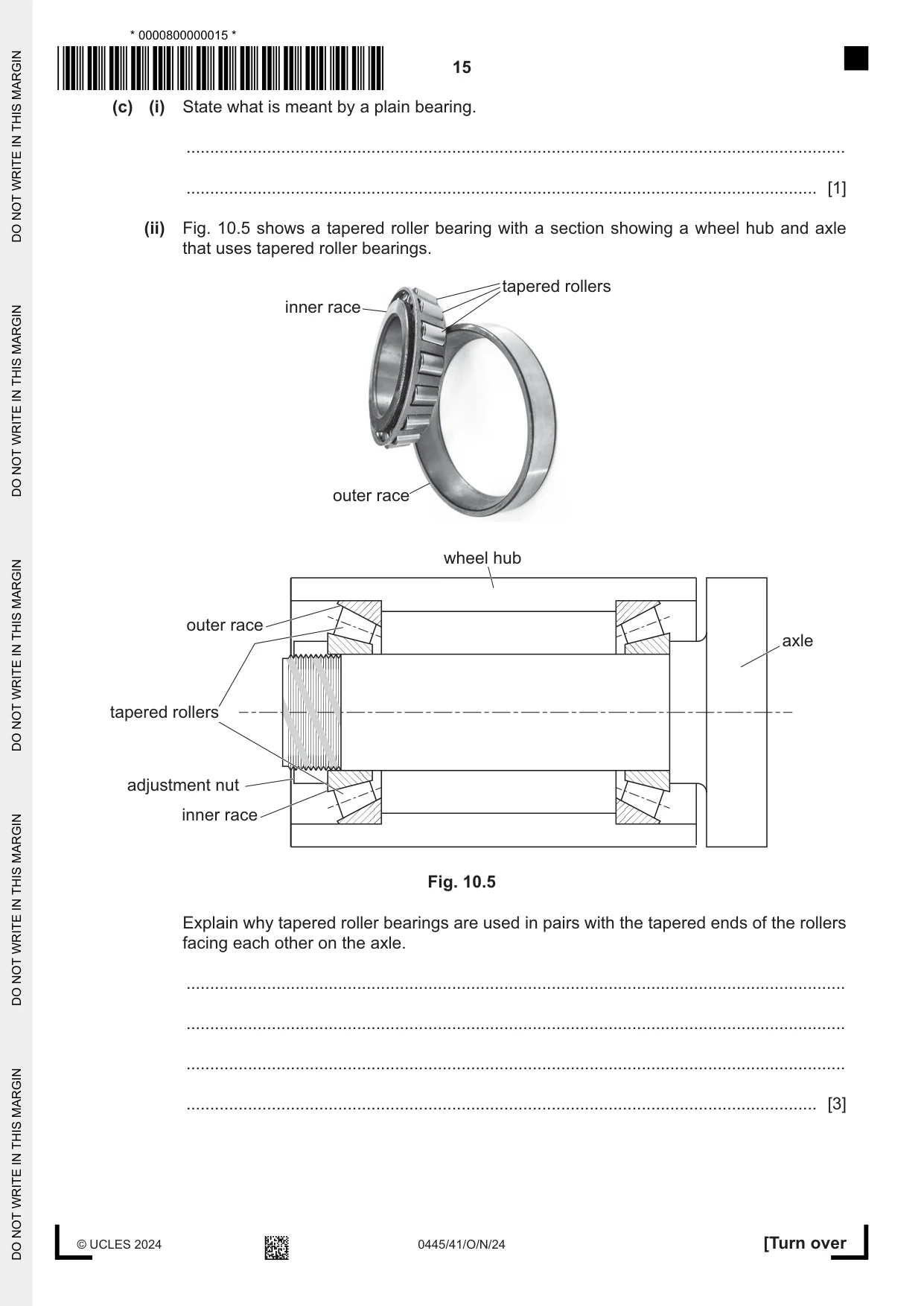
10 (a) Fig. 10.1 shows a mechanism used to raise or lower a gate on a waterway. square taper Y X shaft Fig. 10.1 (i) State the names of parts X and Y that are used in the mechanism. X ........................................................................................................................................ Y ........................................................................................................................................ [2] (ii) Describe how the mechanism in Fig. 10.1 controls rotation of the shaft. ........................................................................................................................................... ........................................................................................................................................... ........................................................................................................................................... ..................................................................................................................................... [3] (iii) Fig. 10.2 shows a cranked handle that can be fitted to the square taper on the end of the shaft allowing the shaft to be turned. tapered square hole Fig. 10.2 Give one benefit of using this method of fitting the handle. ........................................................................................................................................... ..................................................................................................................................... [1] (iv) Explain what is meant by mechanical advantage in a mechanism. ........................................................................................................................................... ........................................................................................................................................... ........................................................................................................................................... ..................................................................................................................................... [2] (v) Use sketches and notes to show how the mechanical advantage and efficiency of the cranked handle in Fig. 10.2 could be increased. [3] (b) Fig. 10.3 shows a small circular saw and the method used to mount the motor. motor 4 slots for mounting motor 4 threaded bolt holes Fig. 10.3 (i) Give two reasons for using four slots to mount the motor. 1 ........................................................................................................................................ ........................................................................................................................................... 2 ........................................................................................................................................ ........................................................................................................................................... [2] (ii) Use sketches and notes to show how the vee belt used to drive the circular saw can be tensioned. [2] (iii) Fig. 10.4 shows the belt and pulley arrangement between the motor and the saw blade. cover on lubrication hole motor pulley Ø64 saw blade pulley Ø46 Fig. 10.4 The motor has a rotational speed of 2850 rpm when not under load. Calculate the rotational speed of the saw blade when the motor is switched on. ........................................................................................................................................... ........................................................................................................................................... ........................................................................................................................................... ..................................................................................................................................... [3] (iv) Explain why the actual rotational speed in use may be less than the calculated speed. ........................................................................................................................................... ........................................................................................................................................... ..................................................................................................................................... [2] (v) Give one reason for having covers over the lubrication holes at each end of the motor. ........................................................................................................................................... ..................................................................................................................................... [1] (c) (i) State what is meant by a plain bearing. ........................................................................................................................................... ..................................................................................................................................... [1] (ii) Fig. 10.5 shows a tapered roller bearing with a section showing a wheel hub and axle that uses tapered roller bearings. tapered rollers inner race outer race wheel hub outer race axle tapered rollers adjustment nut inner race Fig. 10.5 Explain why tapered roller bearings are used in pairs with the tapered ends of the rollers facing each other on the axle. ........................................................................................................................................... ........................................................................................................................................... ........................................................................................................................................... ..................................................................................................................................... [3]
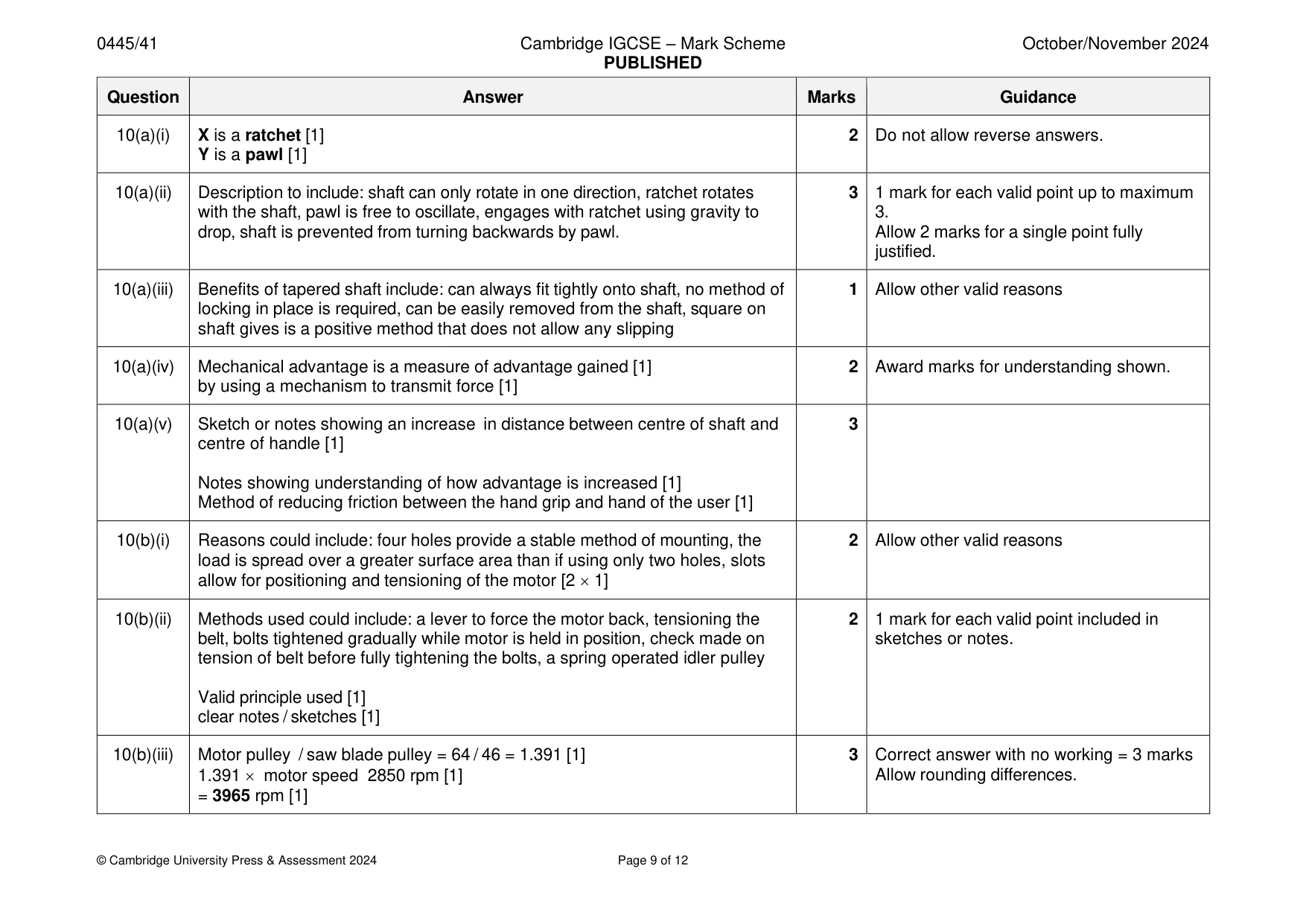
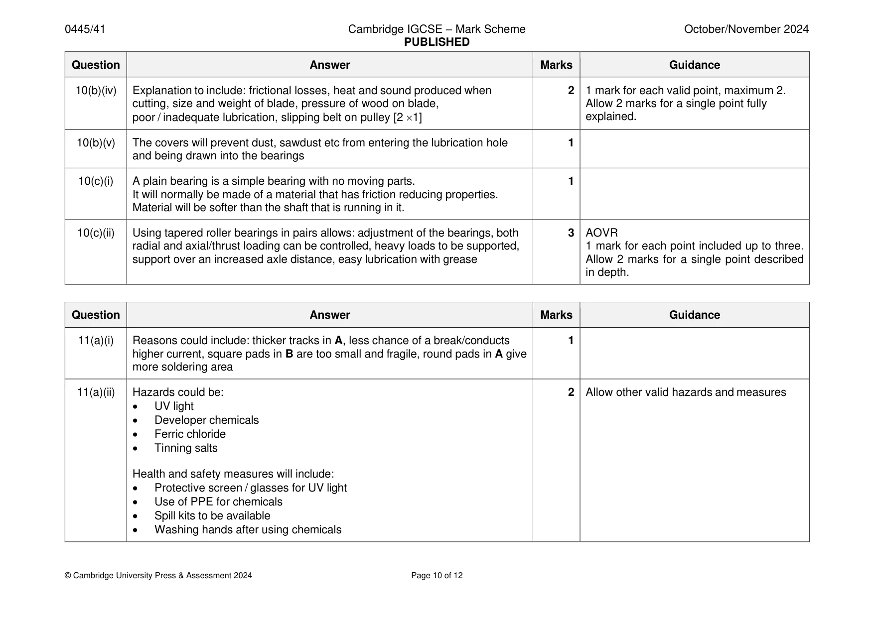
Mark scheme: 10(a)(i) X is a ratchet [1] 2 Do not allow reverse answers. Y is a pawl [1] 10(a)(ii) Description to include: shaft can only rotate in one direction, ratchet rotates 3 1 mark for each valid point up to maximum with the shaft, pawl is free to oscillate, engages with ratchet using gravity to 3. drop, shaft is prevented from turning backwards by pawl. Allow 2 marks for a single point fully justified. 10(a)(iii) Benefits of tapered shaft include: can always fit tightly onto shaft, no method of 1 Allow other valid reasons locking in place is required, can be easily removed from the shaft, square on shaft gives is a positive method that does not allow any slipping 10(a)(iv) Mechanical advantage is a measure of advantage gained [1] 2 Award marks for understanding shown. by using a mechanism to transmit force [1] 10(a)(v) Sketch or notes showing an increase in distance between centre of shaft and 3 centre of handle [1] Notes showing understanding of how advantage is increased [1] Method of reducing friction between the hand grip and hand of the user [1] 10(b)(i) Reasons could include: four holes provide a stable method of mounting, the 2 Allow other valid reasons load is spread over a greater surface area than if using only two holes, slots allow for positioning and tensioning of the motor [2 1] 10(b)(ii) Methods used could include: a lever to force the motor back, tensioning the 2 1 mark for each valid point included in belt, bolts tightened gradually while motor is held in position, check made on sketches or notes. tension of belt before fully tightening the bolts, a spring operated idler pulley Valid principle used [1] clear notes / sketches [1] 10(b)(iii) Motor pulley / saw blade pulley = 64 / 46 = 1.391 [1] 3 Correct answer with no working = 3 marks 1.391 motor speed 2850 rpm [1] Allow rounding differences. = 3965 rpm [1] 10(b)(iv) Explanation to include: frictional losses, heat and sound produced when 2 1 mark for each valid point, maximum 2. cutting, size and weight of blade, pressure of wood on blade, Allow 2 marks for a single point fully poor / inadequate lubrication, slipping belt on pulley [2 1] explained. 10(b)(v) The covers will prevent dust, sawdust etc from entering the lubrication hole 1 and being drawn into the bearings 10(c)(i) A plain bearing is a simple bearing with no moving parts. 1 It will normally be made of a material that has friction reducing properties. Material will be softer than the shaft that is running in it. 10(c)(ii) Using tapered roller bearings in pairs allows: adjustment of the bearings, both 3 AOVR radial and axial/thrust loading can be controlled, heavy loads to be supported, 1 mark for each point included up to three. support over an increased axle distance, easy lubrication with grease Allow 2 marks for a single point described in depth.
Q11 · Two possible designs for a printed circuit board (PCB) to be made using the photoetch…
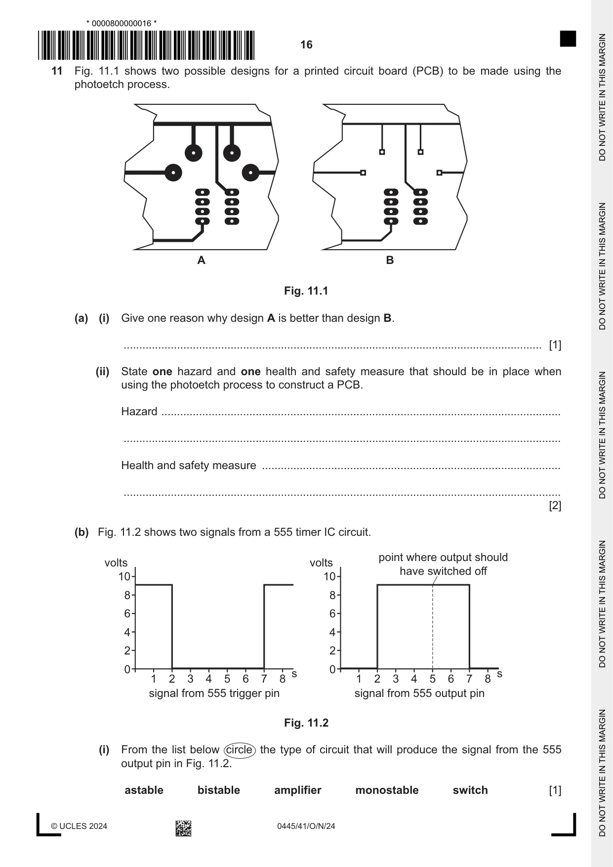
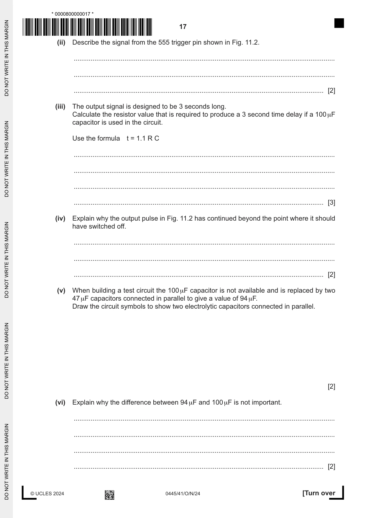
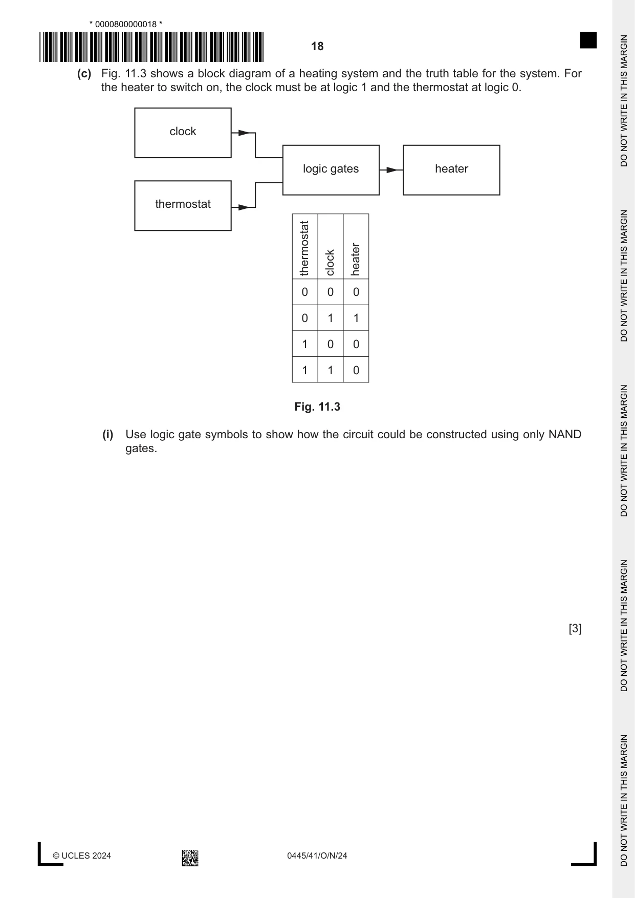
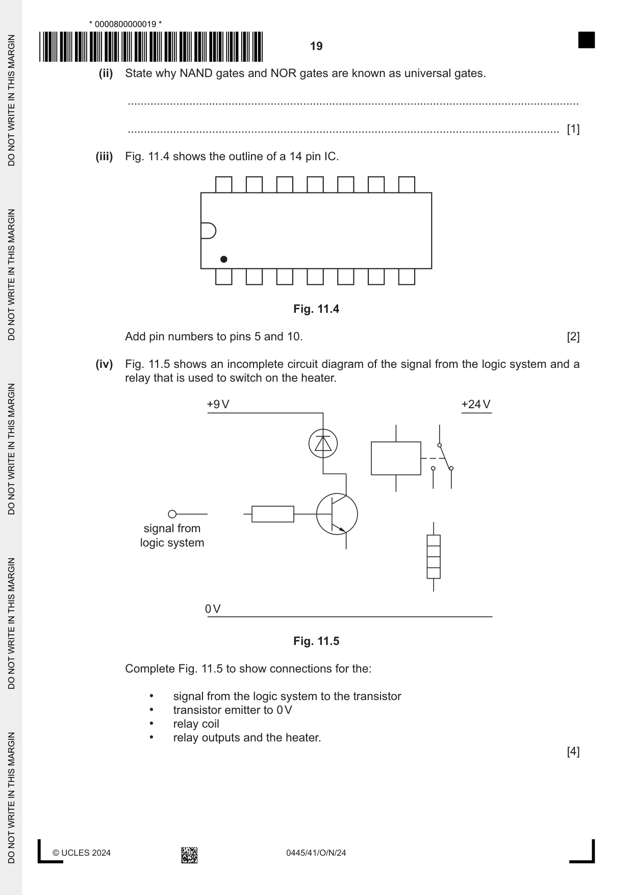
11 Fig. 11.1 shows two possible designs for a printed circuit board (PCB) to be made using the photoetch process. A B Fig. 11.1 (a) (i) Give one reason why design A is better than design B. ..................................................................................................................................... [1] (ii) State one hazard and one health and safety measure that should be in place when using the photoetch process to construct a PCB. Hazard ............................................................................................................................... ........................................................................................................................................... Health and safety measure ............................................................................................... ........................................................................................................................................... [2] (b) Fig. 11.2 shows two signals from a 555 timer IC circuit. point where output should volts volts have switched off 10 10 8 8 6 6 4 4 2 2 0 0 s s 1 2 3 4 5 6 7 8 1 2 3 4 5 6 7 8 signal from 555 trigger pin signal from 555 output pin Fig. 11.2 (i) From the list below circle the type of circuit that will produce the signal from the 555 output pin in Fig. 11.2. astable bistable amplifier monostable switch [1] (ii) Describe the signal from the 555 trigger pin shown in Fig. 11.2. ........................................................................................................................................... ........................................................................................................................................... ..................................................................................................................................... [2] (iii) The output signal is designed to be 3 seconds long. Calculate the resistor value that is required to produce a 3 second time delay if a 100 μF capacitor is used in the circuit. Use the formula t = 1.1 R C ........................................................................................................................................... ........................................................................................................................................... ........................................................................................................................................... ..................................................................................................................................... [3] (iv) Explain why the output pulse in Fig. 11.2 has continued beyond the point where it should have switched off. ........................................................................................................................................... ........................................................................................................................................... ..................................................................................................................................... [2] (v) When building a test circuit the 100 μF capacitor is not available and is replaced by two 47 μF capacitors connected in parallel to give a value of 94 μF. Draw the circuit symbols to show two electrolytic capacitors connected in parallel. [2] (vi) Explain why the difference between 94 μF and 100 μF is not important. ........................................................................................................................................... ........................................................................................................................................... ........................................................................................................................................... ..................................................................................................................................... [2] (c) Fig. 11.3 shows a block diagram of a heating system and the truth table for the system. For the heater to switch on, the clock must be at logic 1 and the thermostat at logic 0. clock logic gates heater thermostat thermostat clock heater 0 0 0 0 1 1 1 0 0 1 1 0 Fig. 11.3 (i) Use logic gate symbols to show how the circuit could be constructed using only NAND gates. [3]
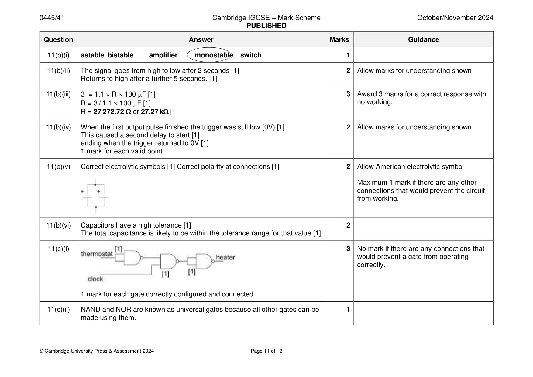
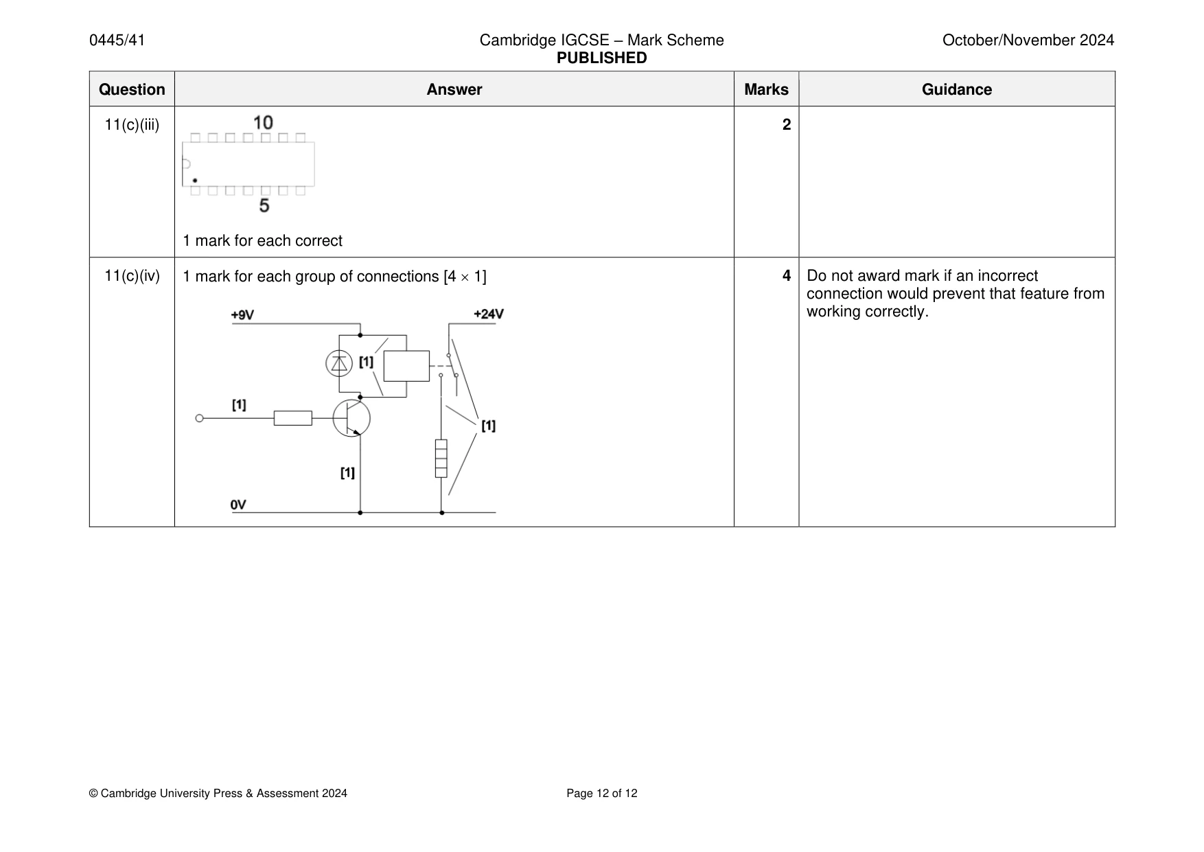
Mark scheme: 11(a)(i) Reasons could include: thicker tracks in A, less chance of a break/conducts 1 higher current, square pads in B are too small and fragile, round pads in A give more soldering area 11(a)(ii) Hazards could be: 2 Allow other valid hazards and measures • UV light • Developer chemicals • Ferric chloride • Tinning salts Health and safety measures will include: • Protective screen / glasses for UV light • Use of PPE for chemicals • Spill kits to be available • Washing hands after using chemicals 11(b)(i) astable bistable amplifier monostable switch 1 11(b)(ii) The signal goes from high to low after 2 seconds [1] 2 Allow marks for understanding shown Returns to high after a further 5 seconds. [1] 11(b)(iii) 3 = 1.1 R 100 F [1] 3 Award 3 marks for a correct response with R = 3 / 1.1 100 F [1] no working. R = 27 272.72 or 27.27 k [1] 11(b)(iv) When the first output pulse finished the trigger was still low (0V) [1] 2 Allow marks for understanding shown This caused a second delay to start [1] ending when the trigger returned to 0V [1] 1 mark for each valid point. 11(b)(v) Correct electrolytic symbols [1] Correct polarity at connections [1] 2 Allow American electrolytic symbol Maximum 1 mark if there are any other connections that would prevent the circuit from working. 11(b)(vi) Capacitors have a high tolerance [1] 2 The total capacitance is likely to be within the tolerance range for that value [1] 11(c)(i) 3 No mark if there are any connections that would prevent a gate from operating correctly. 1 mark for each gate correctly configured and connected. 11(c)(ii) NAND and NOR are known as universal gates because all other gates can be 1 made using them. 11(c)(iii) 2 1 mark for each correct 11(c)(iv) 1 mark for each group of connections [4 1] 4 Do not award mark if an incorrect connection would prevent that feature from working correctly.
What was in this paper
The subtopics covered by these 11 questions, and how many questions each got. Open one in a new tab to see every Cambridge question on it.
What you needed in this session
Cambridge’s own grade thresholds for 2024 Oct/Nov, Paper 4 · Variant 1. A higher threshold means an easier paper — the bar moves with how the cohort did.