Cambridge IGCSE Design and Technology 0445 — 2025 Oct/Nov Paper 4 · Variant 1
0445/41/O/N/25 · 12 questions · 50 marks · 60 min
The question paper and its mark scheme, free to read here and free to download. This is Cambridge’s own paper, exactly as it was sat.
Question paper20 pages


Mark scheme16 pages
Answers below. Sit the paper first if you are practising.
Questions as text
Q1 · Two structures made from composite materials
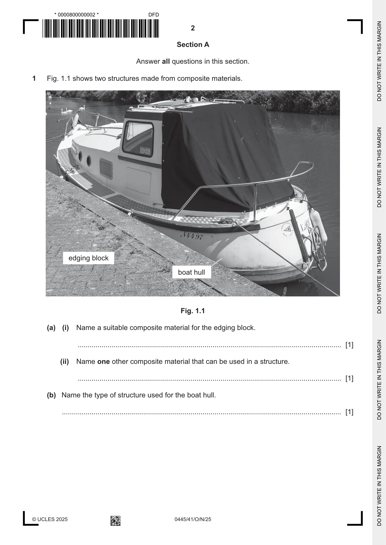
1 Fig. 1.1 shows two structures made from composite materials. edging block boat hull Fig. 1.1 (a) (i) Name a suitable composite material for the edging block. ..................................................................................................................................... [1] (ii) Name one other composite material that can be used in a structure. ..................................................................................................................................... [1] (b) Name the type of structure used for the boat hull. ............................................................................................................................................. [1]
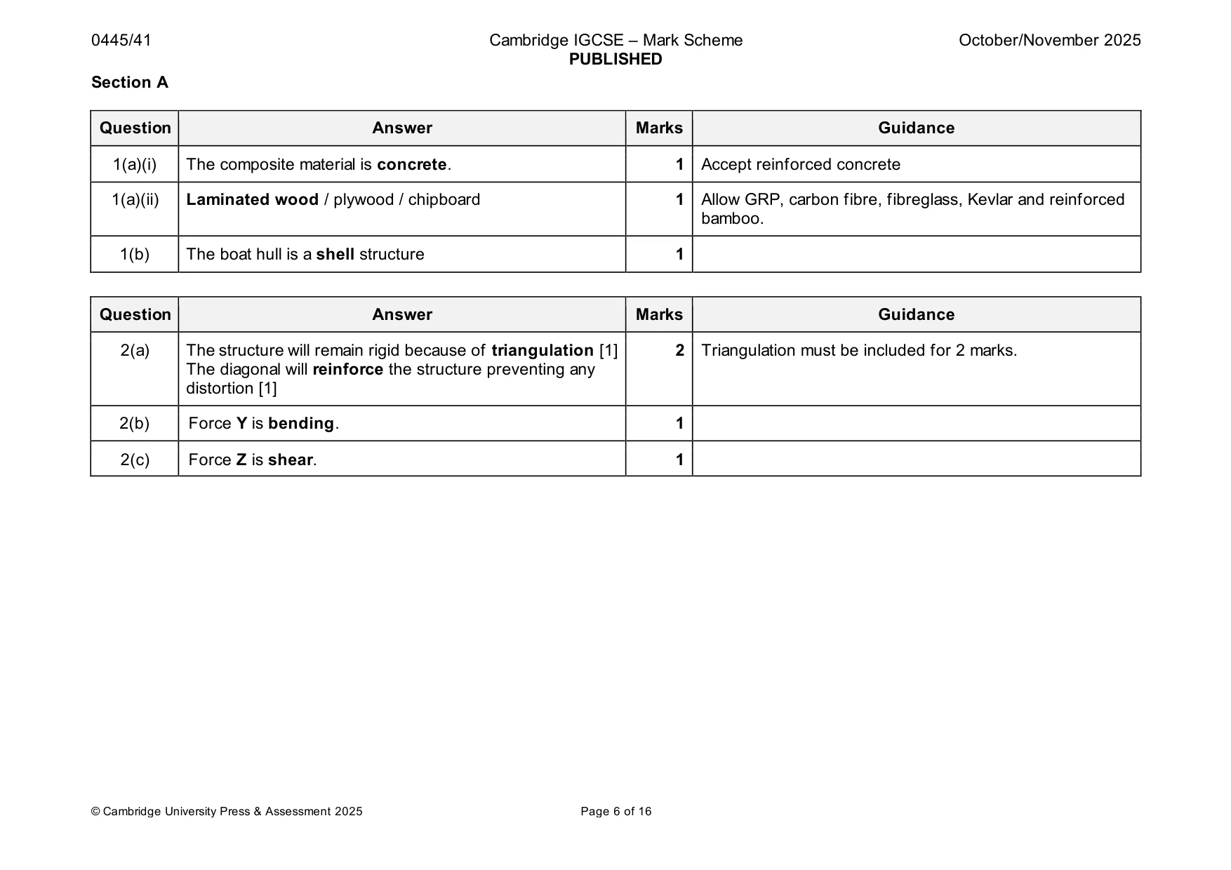
Mark scheme: Question Answer Marks Guidance 1(a)(i) The composite material is concrete. 1 Accept reinforced concrete 1(a)(ii) Laminated wood / plywood / chipboard 1 Allow GRP, carbon fibre, fibreglass, Kevlar and reinforced bamboo. 1(b) The boat hull is a shell structure 1
Q2 · A rigid gate structure made from welded steel tubes
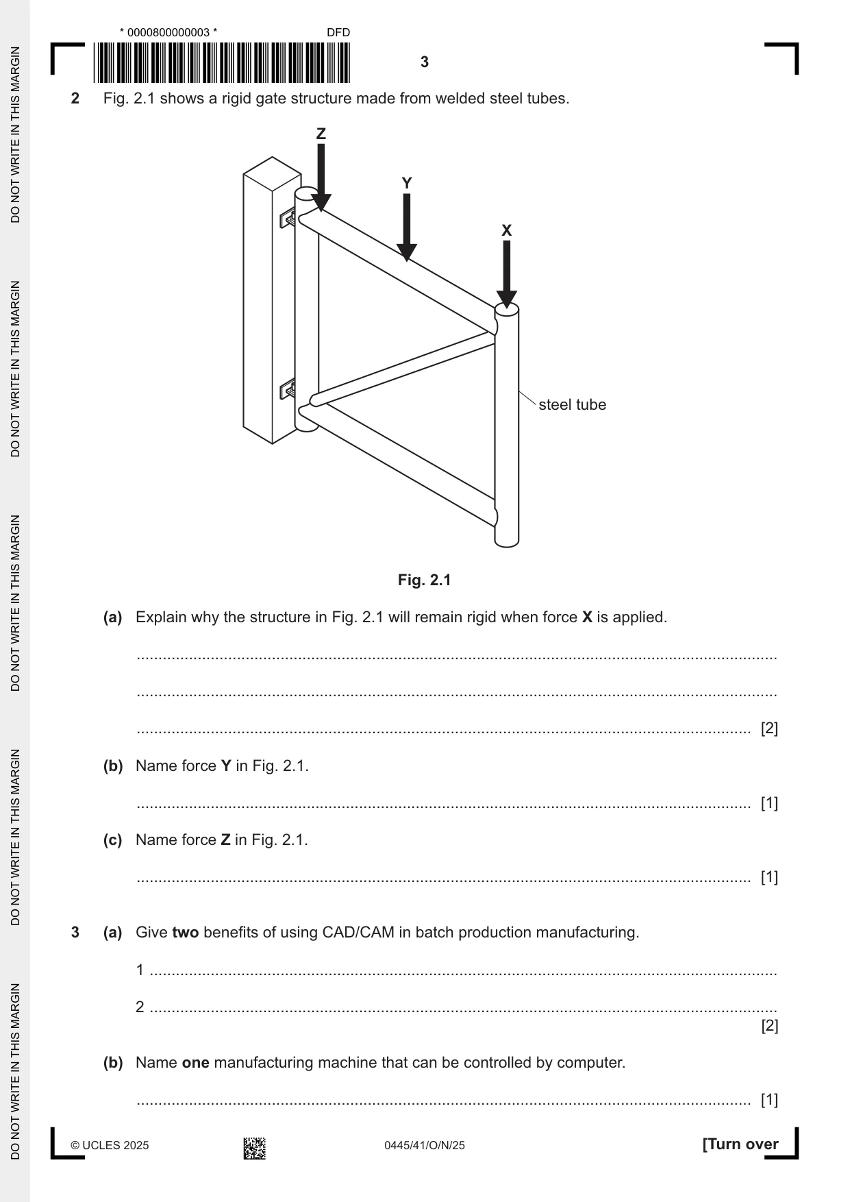
2 Fig. 2.1 shows a rigid gate structure made from welded steel tubes. Z Y X steel tube Fig. 2.1 (a) Explain why the structure in Fig. 2.1 will remain rigid when force X is applied. ................................................................................................................................................... ................................................................................................................................................... ............................................................................................................................................. [2] (b) Name force Y in Fig. 2.1. ............................................................................................................................................. [1] (c) Name force Z in Fig. 2.1. ............................................................................................................................................. [1]
Mark scheme: 2(a) The structure will remain rigid because of triangulation [1] 2 Triangulation must be included for 2 marks. The diagonal will reinforce the structure preventing any distortion [1] 2(b) Force Y is bending. 1 2(c) Force Z is shear. 1
Q3 · Give two benefits of using CAD/CAM in batch production manufacturing
3 (a) Give two benefits of using CAD/CAM in batch production manufacturing. 1 ................................................................................................................................................ 2 ................................................................................................................................................ [2] (b) Name one manufacturing machine that can be controlled by computer. ............................................................................................................................................. [1]
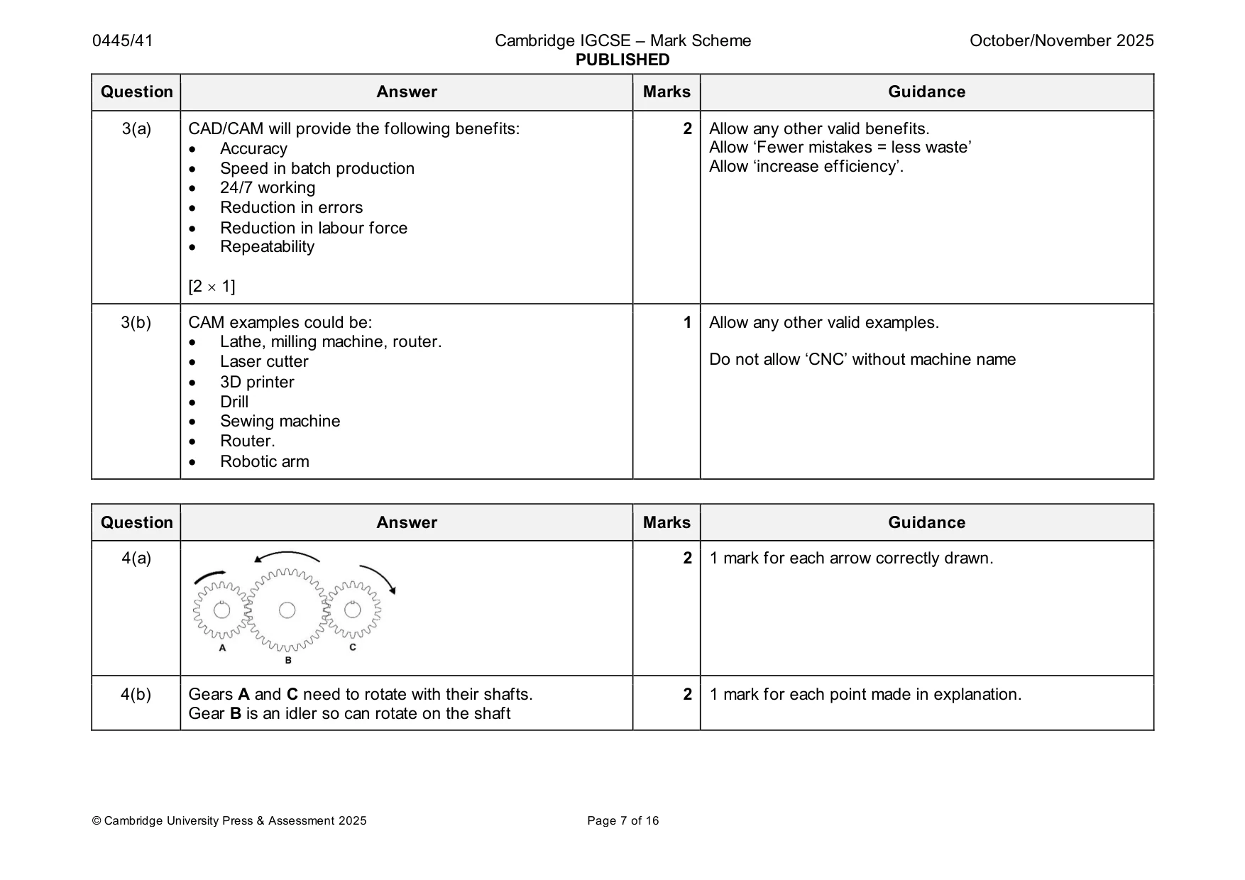
Mark scheme: 3(a) CAD/CAM will provide the following benefits: 2 Allow any other valid benefits. • Accuracy Allow ‘Fewer mistakes = less waste’ • Speed in batch production Allow ‘increase efficiency’. • 24/7 working • Reduction in errors • Reduction in labour force • Repeatability [2 1] 3(b) CAM examples could be: 1 Allow any other valid examples. • Lathe, milling machine, router. • Laser cutter Do not allow ‘CNC’ without machine name • 3D printer • Drill • Sewing machine • Router. • Robotic arm
Q4 · Three spur gears used to connect the drive shafts on gears A and C
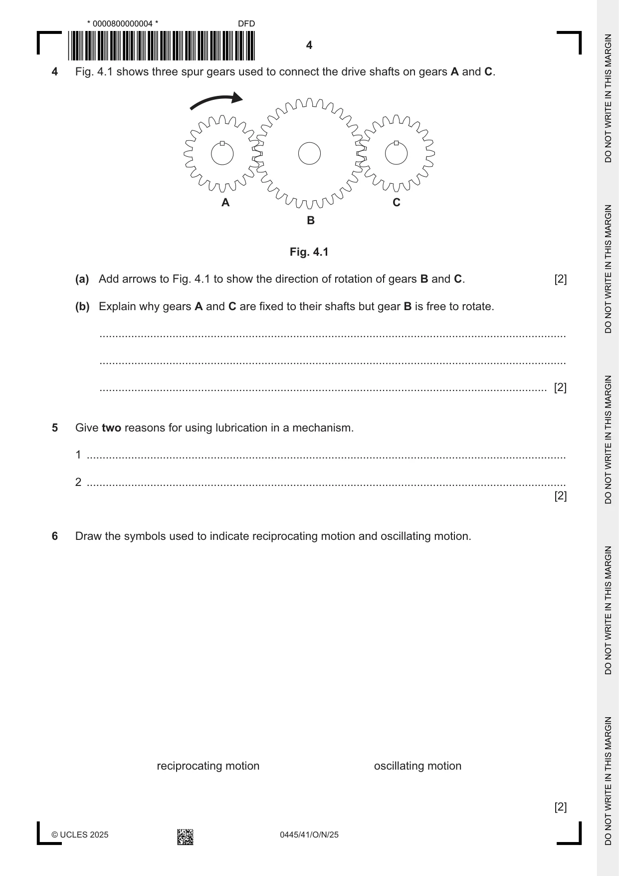
4 Fig. 4.1 shows three spur gears used to connect the drive shafts on gears A and C. A C B Fig. 4.1 (a) Add arrows to Fig. 4.1 to show the direction of rotation of gears B and C. [2] (b) Explain why gears A and C are fixed to their shafts but gear B is free to rotate. ................................................................................................................................................... ................................................................................................................................................... ............................................................................................................................................. [2]
Mark scheme: 4(a) 2 1 mark for each arrow correctly drawn. 4(b) Gears A and C need to rotate with their shafts. 2 1 mark for each point made in explanation. Gear B is an idler so can rotate on the shaft
Q5 · Give two reasons for using lubrication in a mechanism
5 Give two reasons for using lubrication in a mechanism. 1 ....................................................................................................................................................... 2 ....................................................................................................................................................... [2]
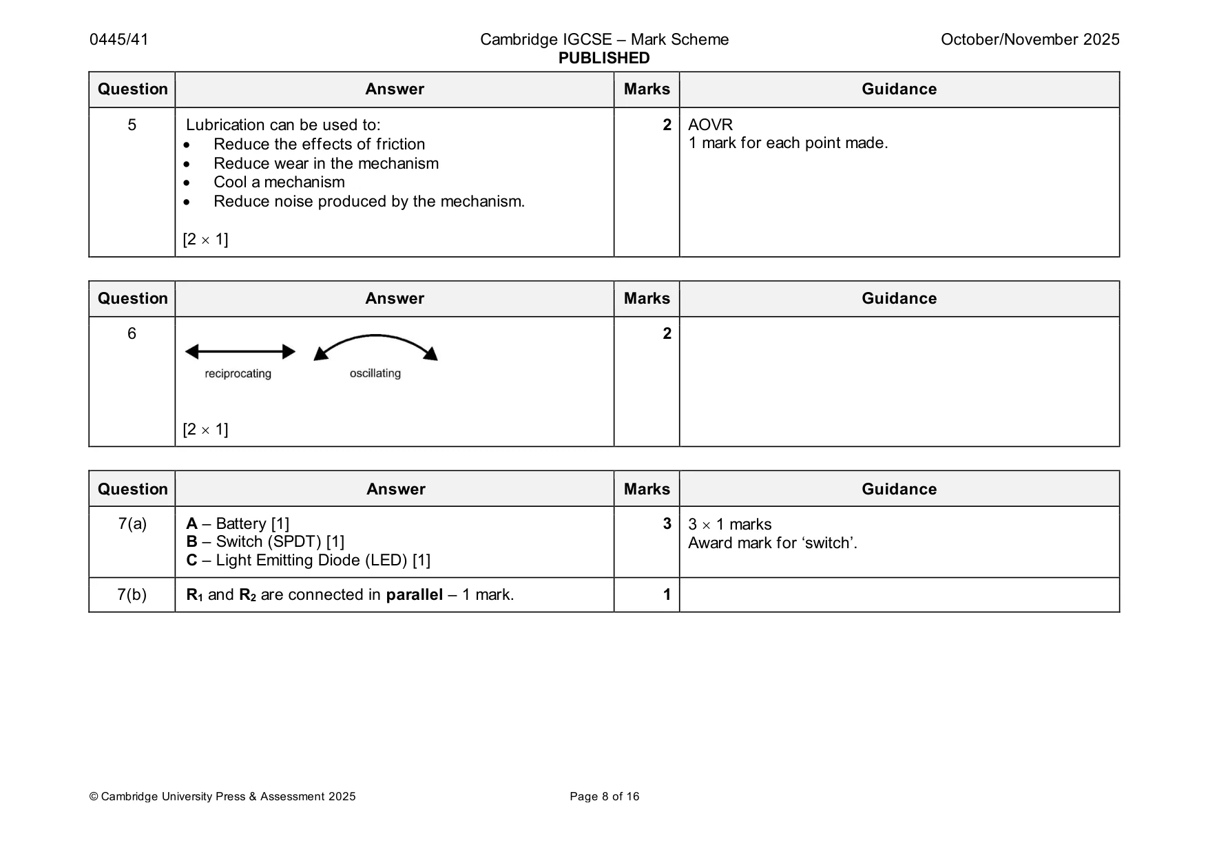
Mark scheme: 5 Lubrication can be used to: 2 AOVR • Reduce the effects of friction 1 mark for each point made. • Reduce wear in the mechanism • Cool a mechanism • Reduce noise produced by the mechanism. [2 1]
Q6 · Draw the symbols used to indicate reciprocating motion and oscillating motion
6 Draw the symbols used to indicate reciprocating motion and oscillating motion. reciprocating motion oscillating motion [2]
Mark scheme: 6 2 [2 1]
Q7 · Part of an electronic circuit diagram
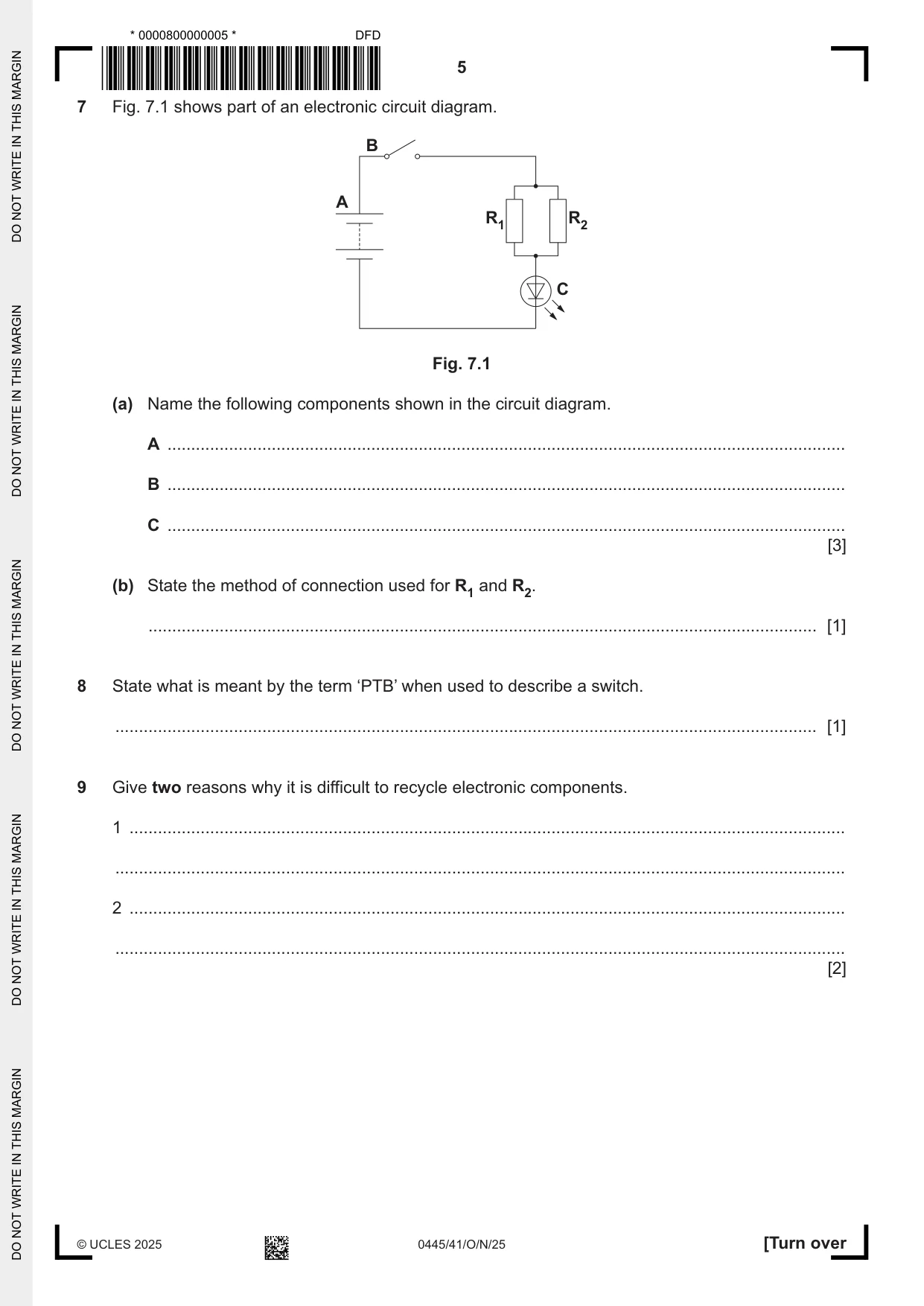
7 Fig. 7.1 shows part of an electronic circuit diagram. B A R1 R2 C Fig. 7.1 (a) Name the following components shown in the circuit diagram. A ............................................................................................................................................... B ............................................................................................................................................... C ............................................................................................................................................... [3] (b) State the method of connection used for R1 and R2. ............................................................................................................................................. [1]
Mark scheme: 7(a) A – Battery [1] 3 3 1 marks B – Switch (SPDT) [1] Award mark for ‘switch’. C – Light Emitting Diode (LED) [1] 7(b) R1 and R2 are connected in parallel – 1 mark. 1
Q8 · State what is meant by the term ‘PTB’ when used to describe a switch
8 State what is meant by the term ‘PTB’ when used to describe a switch. .................................................................................................................................................... [1]
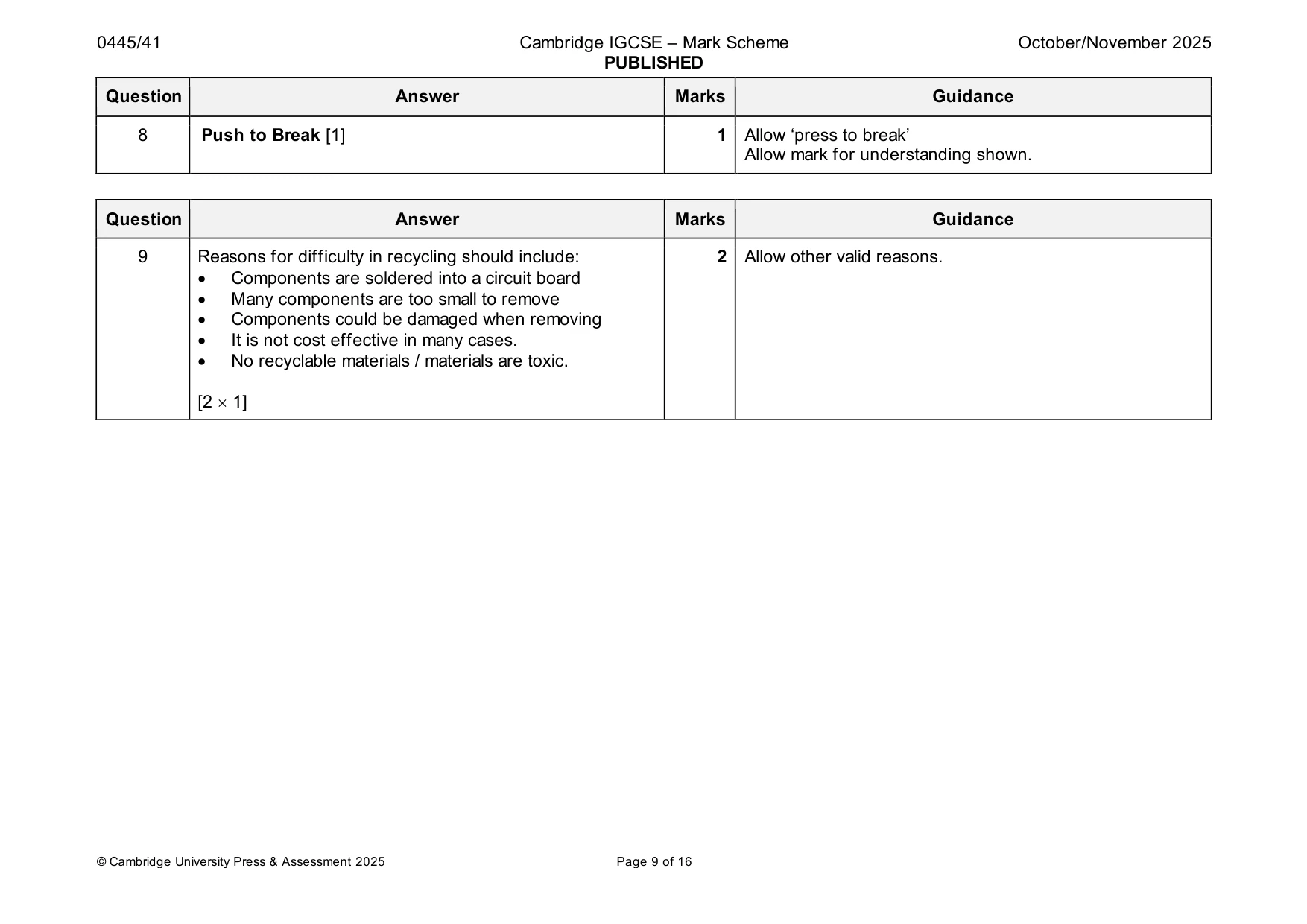
Mark scheme: 8 Push to Break [1] 1 Allow ‘press to break’ Allow mark for understanding shown.
Q9 · Give two reasons why it is difficult to recycle electronic components
9 Give two reasons why it is difficult to recycle electronic components. 1 ....................................................................................................................................................... .......................................................................................................................................................... 2 ....................................................................................................................................................... .......................................................................................................................................................... [2]
Mark scheme: 9 Reasons for difficulty in recycling should include: 2 Allow other valid reasons. • Components are soldered into a circuit board • Many components are too small to remove • Components could be damaged when removing • It is not cost effective in many cases. • No recyclable materials / materials are toxic. [2 1] Section B
Q10 · A peg puller for removing large tent pegs from the ground
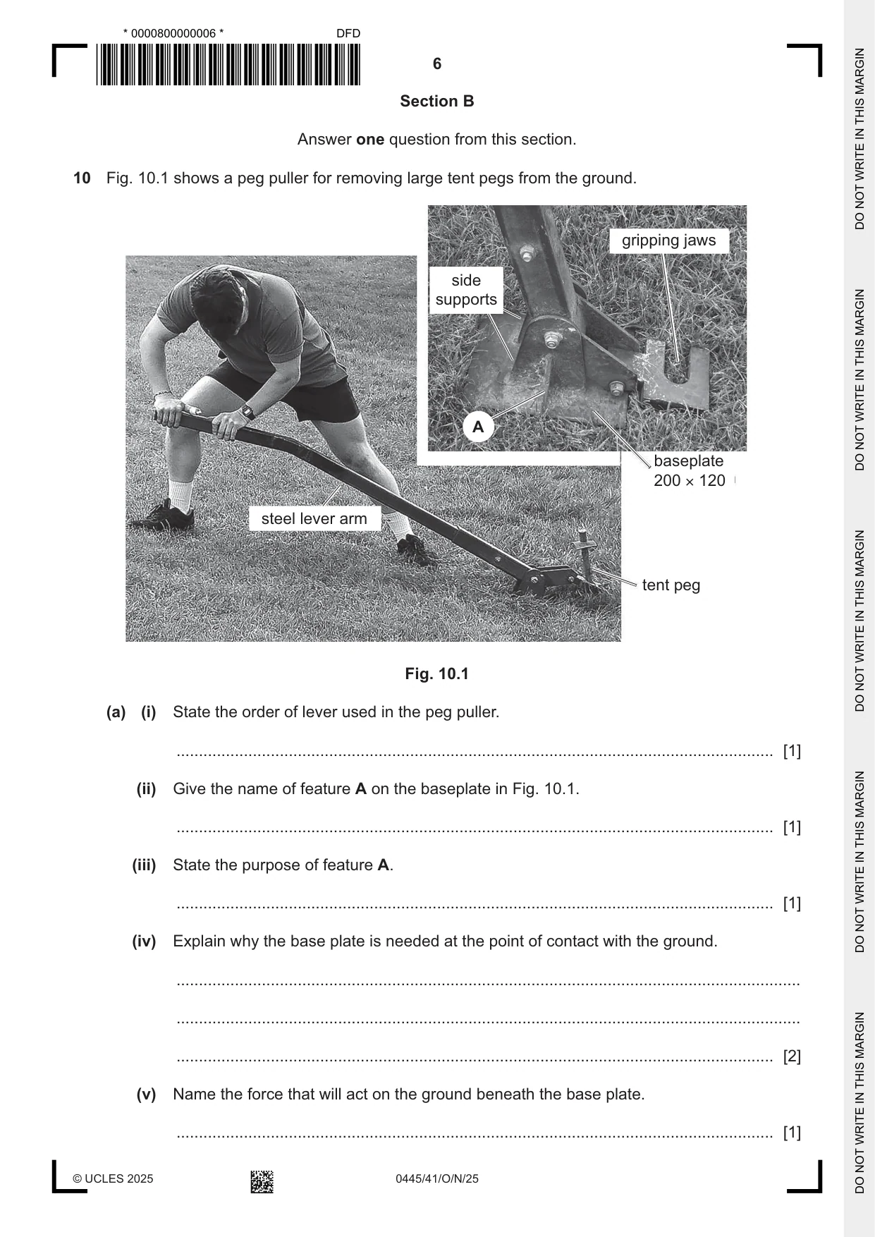
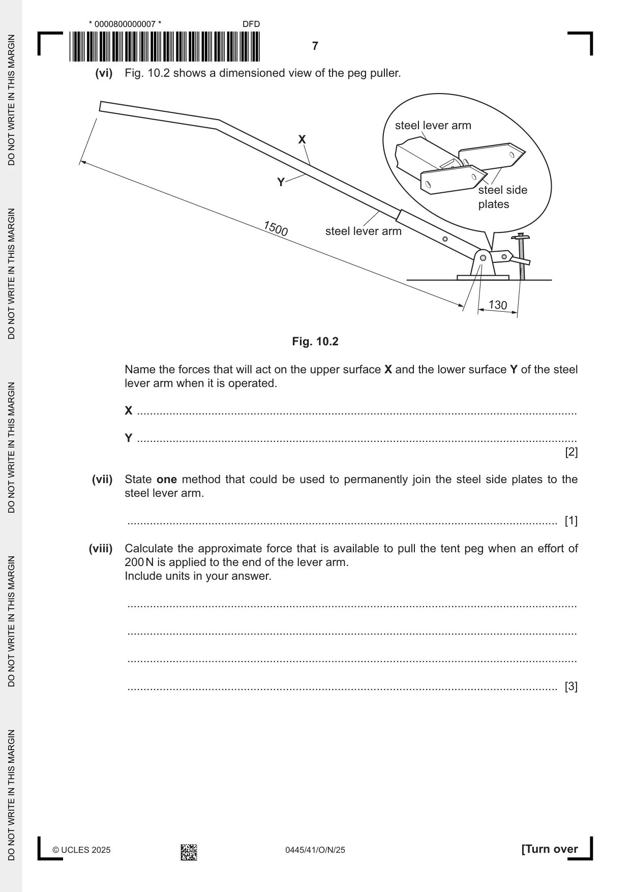
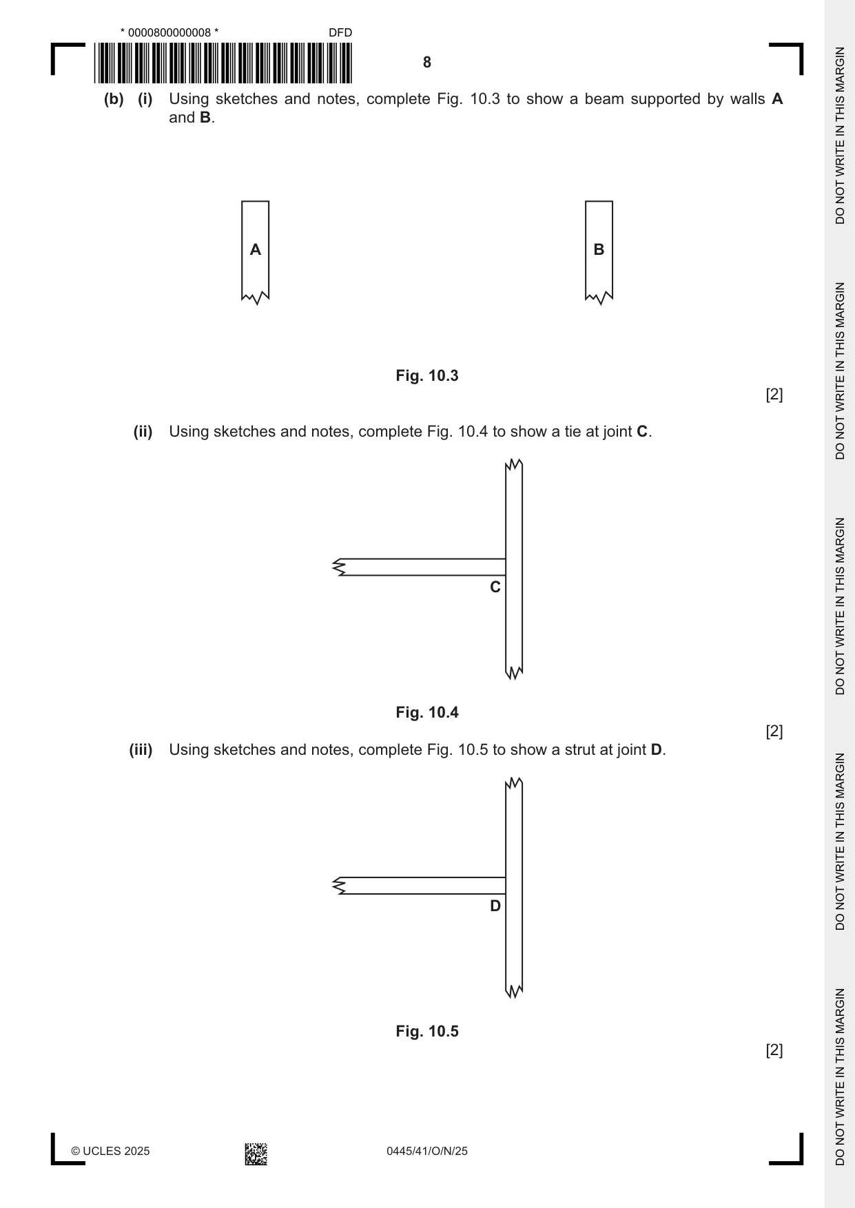
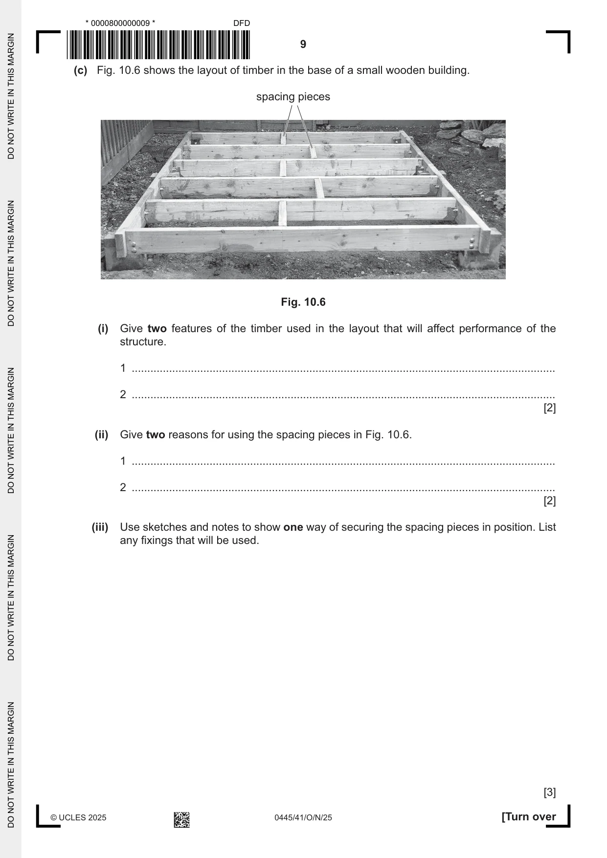
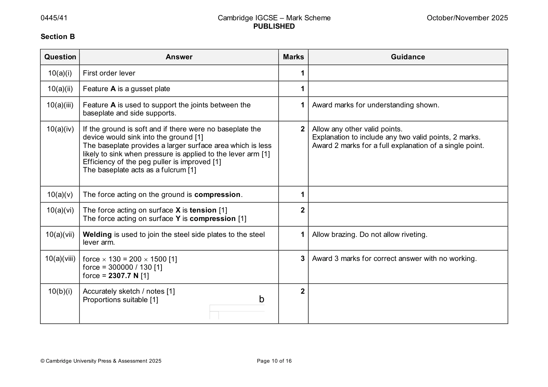
10 Fig. 10.1 shows a peg puller for removing large tent pegs from the ground. gripping jaws side supports A baseplate 200 × 120 steel lever arm tent peg Fig. 10.1 (a) (i) State the order of lever used in the peg puller. ..................................................................................................................................... [1] (ii) Give the name of feature A on the baseplate in Fig. 10.1. ..................................................................................................................................... [1] (iii) State the purpose of feature A. ..................................................................................................................................... [1] (iv) Explain why the base plate is needed at the point of contact with the ground. ........................................................................................................................................... ........................................................................................................................................... ..................................................................................................................................... [2] (v) Name the force that will act on the ground beneath the base plate. ..................................................................................................................................... [1] (vi) Fig. 10.2 shows a dimensioned view of the peg puller. steel lever arm X Y steel side plates 1500 steel lever arm 130 Fig. 10.2 Name the forces that will act on the upper surface X and the lower surface Y of the steel lever arm when it is operated. X ........................................................................................................................................ Y ........................................................................................................................................ [2] (vii) State one method that could be used to permanently join the steel side plates to the steel lever arm. ..................................................................................................................................... [1] (viii) Calculate the approximate force that is available to pull the tent peg when an effort of 200 N is applied to the end of the lever arm. Include units in your answer. ........................................................................................................................................... ........................................................................................................................................... ........................................................................................................................................... ..................................................................................................................................... [3] (b) (i) Using sketches and notes, complete Fig. 10.3 to show a beam supported by walls A and B. A B Fig. 10.3 [2] (ii) Using sketches and notes, complete Fig. 10.4 to show a tie at joint C. C Fig. 10.4 [2] (iii) Using sketches and notes, complete Fig. 10.5 to show a strut at joint D. D Fig. 10.5 [2] (c) Fig. 10.6 shows the layout of timber in the base of a small wooden building. spacing pieces Fig. 10.6 (i) Give two features of the timber used in the layout that will affect performance of the structure. 1 ........................................................................................................................................ 2 ........................................................................................................................................ [2] (ii) Give two reasons for using the spacing pieces in Fig. 10.6. 1 ........................................................................................................................................ 2 ........................................................................................................................................ [2] (iii) Use sketches and notes to show one way of securing the spacing pieces in position. List any fixings that will be used. [3]
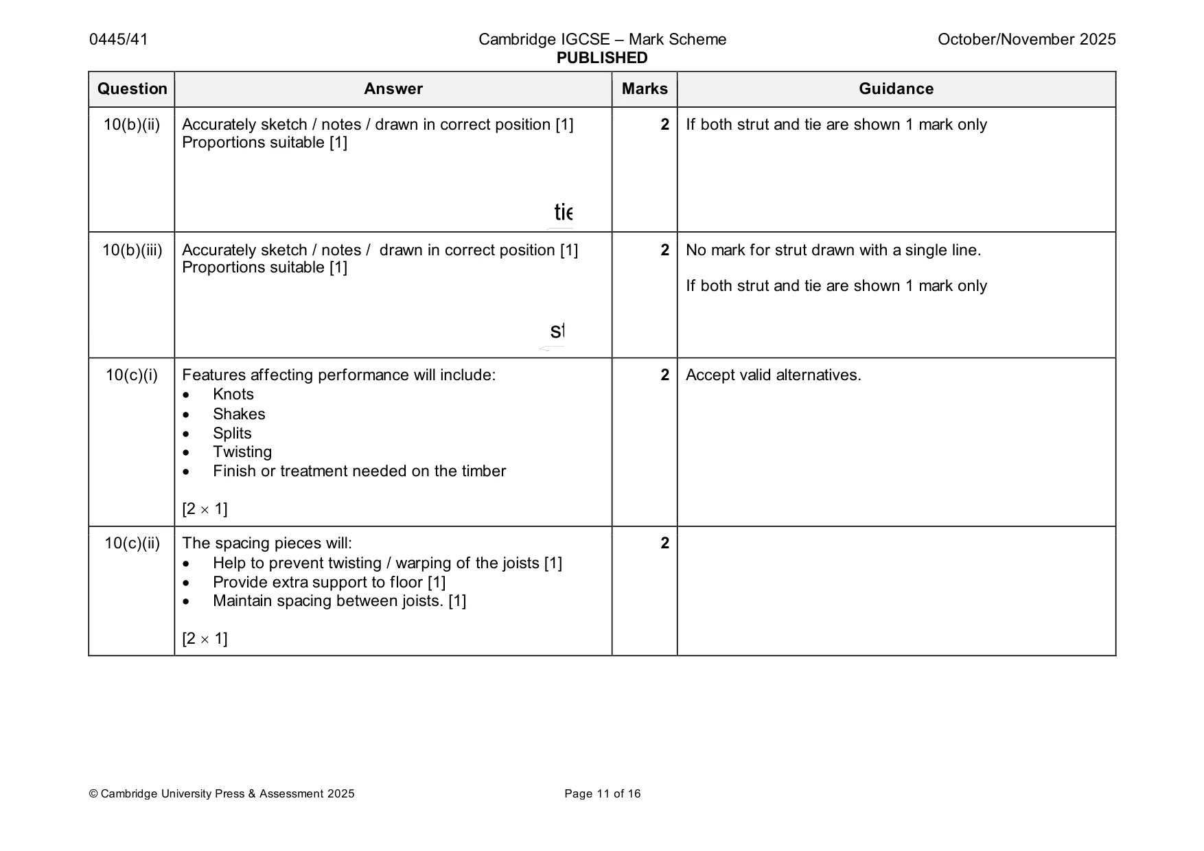
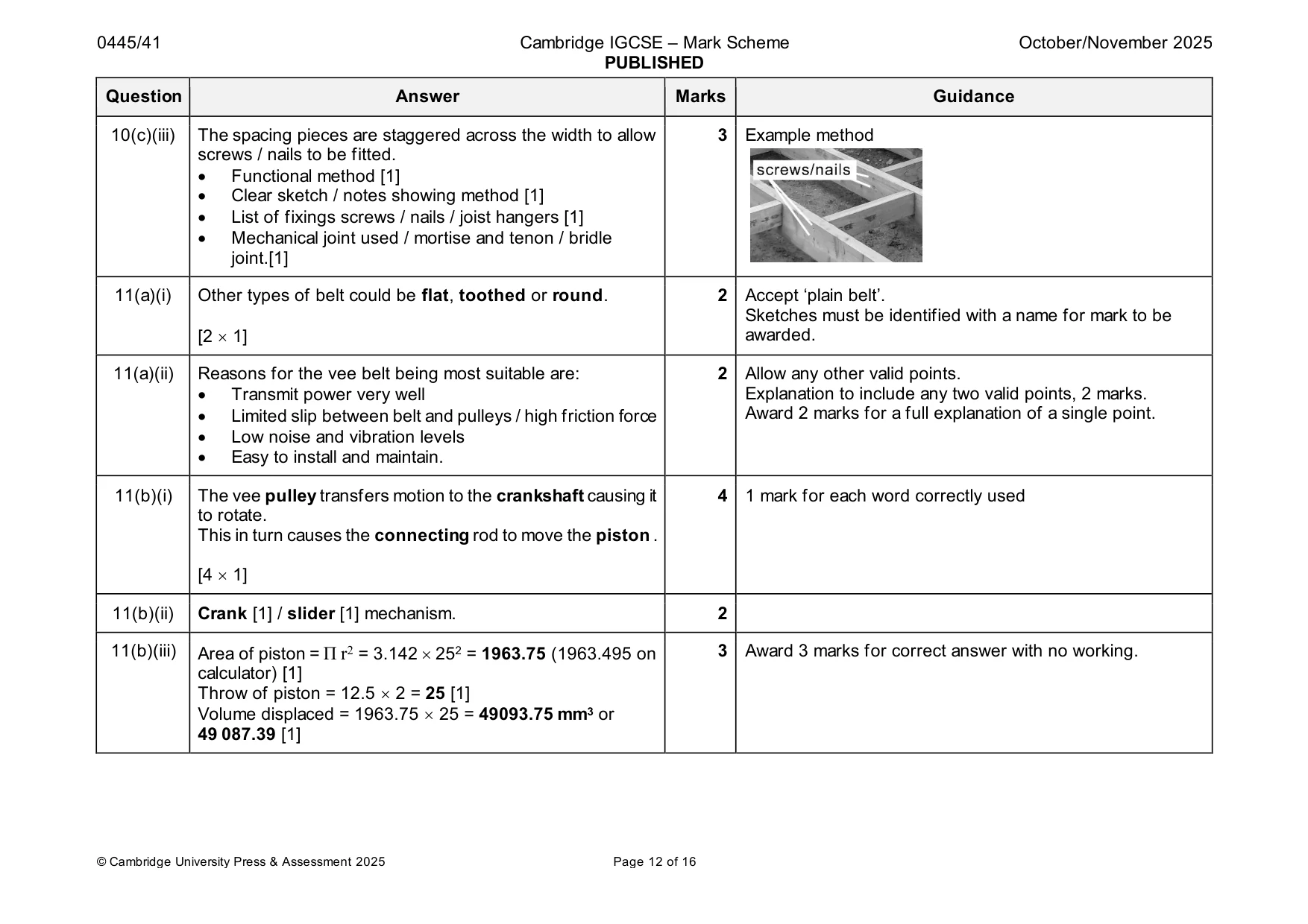
Mark scheme: 10(a)(i) First order lever 1 10(a)(ii) Feature A is a gusset plate 1 10(a)(iii) Feature A is used to support the joints between the 1 Award marks for understanding shown. baseplate and side supports. 10(a)(iv) If the ground is soft and if there were no baseplate the 2 Allow any other valid points. device would sink into the ground [1] Explanation to include any two valid points, 2 marks. The baseplate provides a larger surface area which is less Award 2 marks for a full explanation of a single point. likely to sink when pressure is applied to the lever arm [1] Efficiency of the peg puller is improved [1] The baseplate acts as a fulcrum [1] 10(a)(v) The force acting on the ground is compression. 1 10(a)(vi) The force acting on surface X is tension [1] 2 The force acting on surface Y is compression [1] 10(a)(vii) Welding is used to join the steel side plates to the steel 1 Allow brazing. Do not allow riveting. lever arm. 10(a)(viii) force 130 = 200 1500 [1] 3 Award 3 marks for correct answer with no working. force = 300000 / 130 [1] force = 2307.7 N [1] 10(b)(i) Accurately sketch / notes [1] 2 Proportions suitable [1] 10(b)(ii) Accurately sketch / notes / drawn in correct position [1] 2 If both strut and tie are shown 1 mark only Proportions suitable [1] 10(b)(iii) Accurately sketch / notes / drawn in correct position [1] 2 No mark for strut drawn with a single line. Proportions suitable [1] If both strut and tie are shown 1 mark only 10(c)(i) Features affecting performance will include: 2 Accept valid alternatives. • Knots • Shakes • Splits • Twisting • Finish or treatment needed on the timber [2 1] 10(c)(ii) The spacing pieces will: 2 • Help to prevent twisting / warping of the joists [1] • Provide extra support to floor [1] • Maintain spacing between joists. [1] [2 1] 10(c)(iii) The spacing pieces are staggered across the width to allow 3 Example method screws / nails to be fitted. • Functional method [1] • Clear sketch / notes showing method [1] • List of fixings screws / nails / joist hangers [1] • Mechanical joint used / mortise and tenon / bridle joint.[1]
Q11 · An air compressor driven by an electric motor
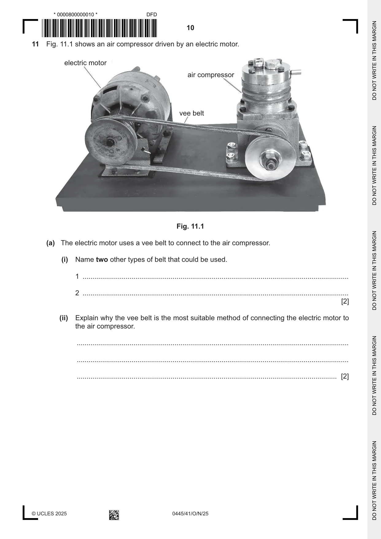
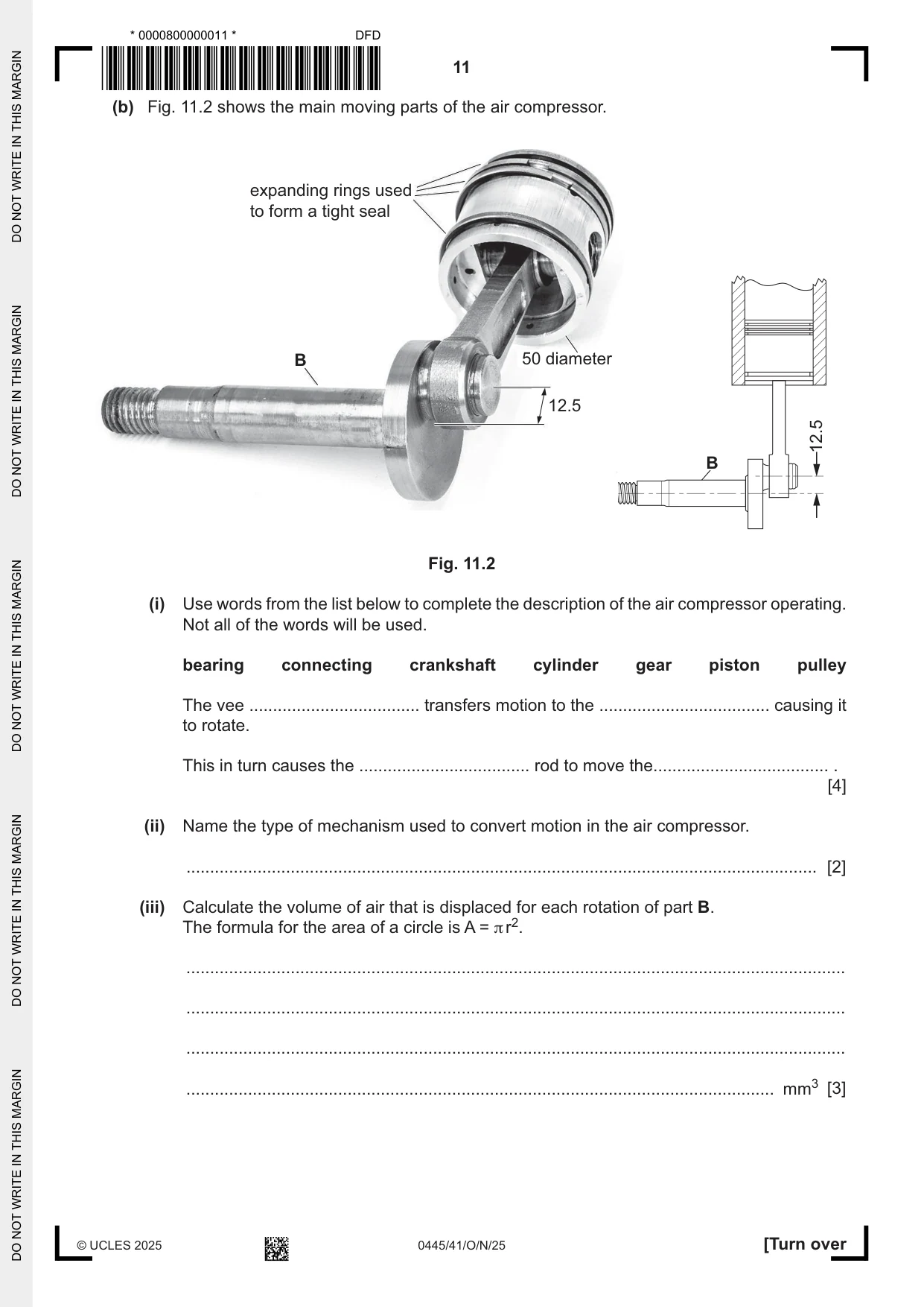
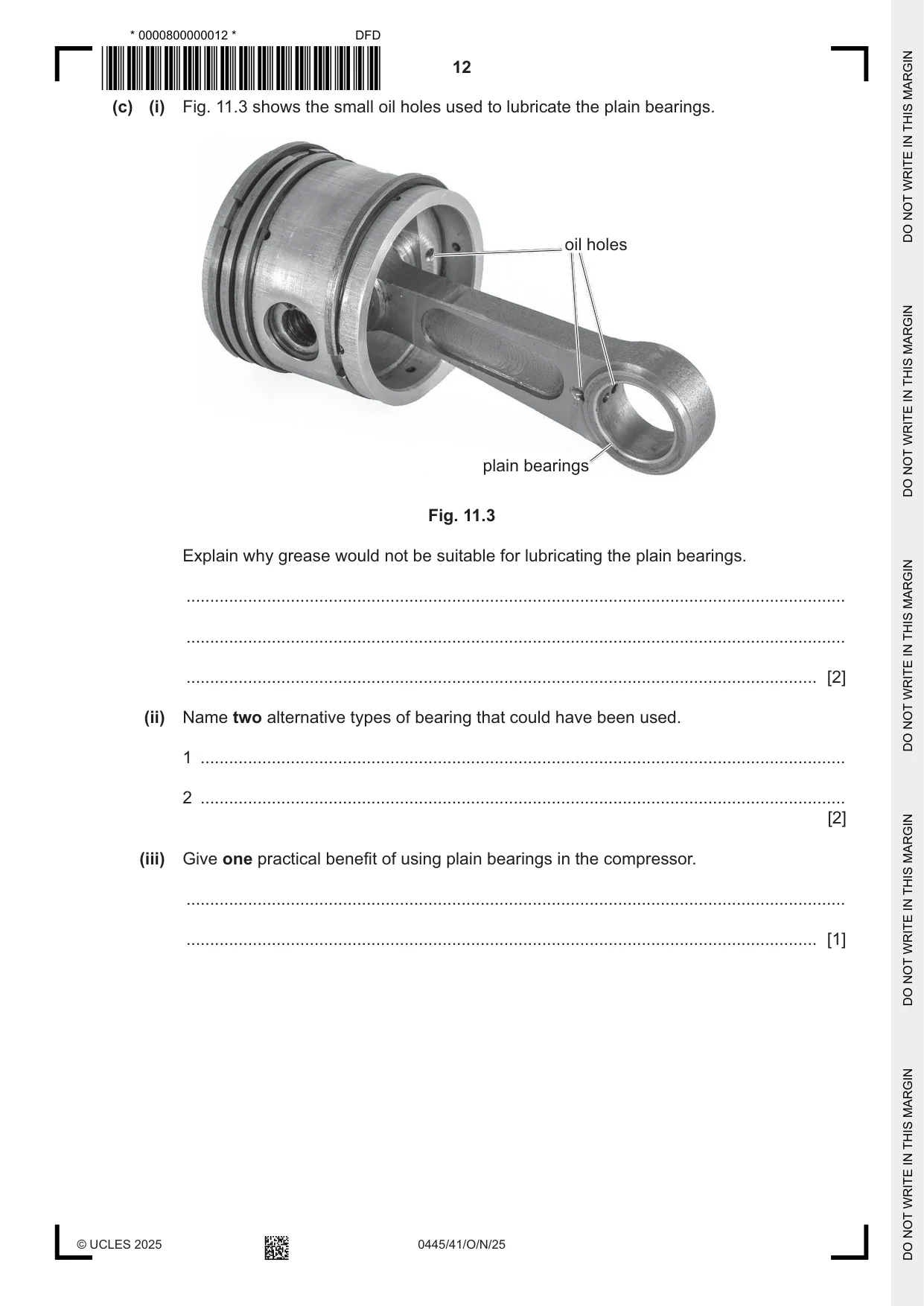
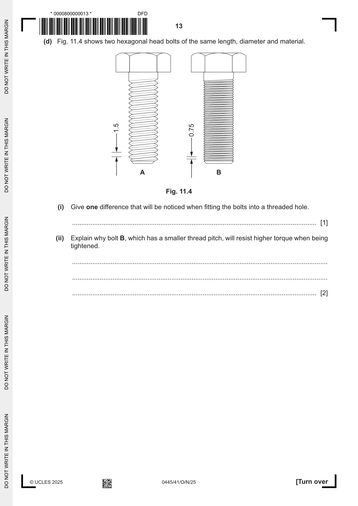
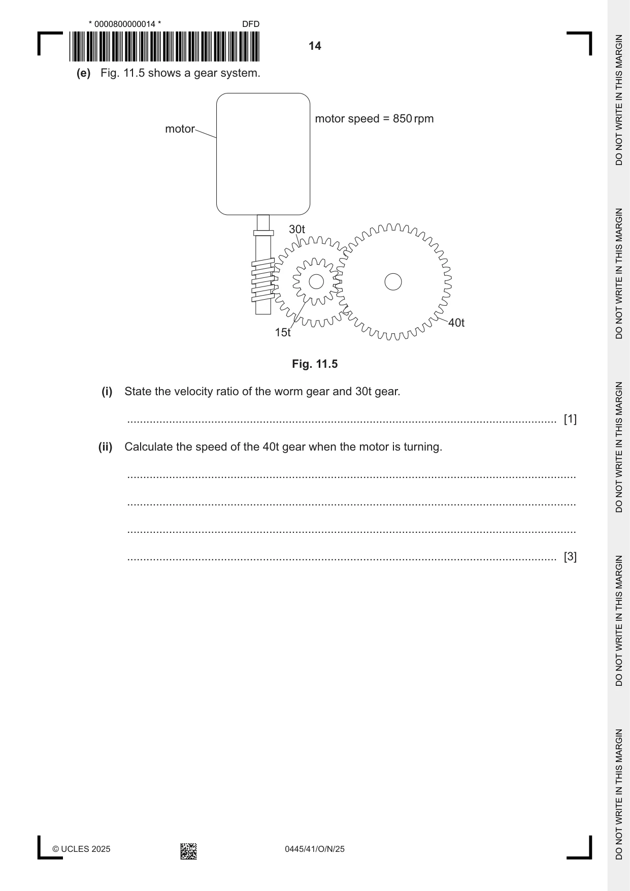
11 Fig. 11.1 shows an air compressor driven by an electric motor. electric motor air compressor vee belt Fig. 11.1 (a) The electric motor uses a vee belt to connect to the air compressor. (i) Name two other types of belt that could be used. 1 ........................................................................................................................................ 2 ........................................................................................................................................ [2] (ii) Explain why the vee belt is the most suitable method of connecting the electric motor to the air compressor. ........................................................................................................................................... ........................................................................................................................................... ..................................................................................................................................... [2] (b) Fig. 11.2 shows the main moving parts of the air compressor. expanding rings used to form a tight seal B 50 diameter 12.5 12.5 B Fig. 11.2 (i) Use words from the list below to complete the description of the air compressor operating. Not all of the words will be used. bearing connecting crankshaft cylinder gear piston pulley The vee .................................... transfers motion to the .................................... causing it to rotate. This in turn causes the .................................... rod to move the..................................... . [4] (ii) Name the type of mechanism used to convert motion in the air compressor. ..................................................................................................................................... [2] (iii) Calculate the volume of air that is displaced for each rotation of part B. The formula for the area of a circle is A = π r2. ........................................................................................................................................... ........................................................................................................................................... ........................................................................................................................................... ............................................................................................................................ mm3 [3] (c) (i) Fig. 11.3 shows the small oil holes used to lubricate the plain bearings. oil holes plain bearings Fig. 11.3 Explain why grease would not be suitable for lubricating the plain bearings. ........................................................................................................................................... ........................................................................................................................................... ..................................................................................................................................... [2] (ii) Name two alternative types of bearing that could have been used. 1 ........................................................................................................................................ 2 ........................................................................................................................................ [2] (iii) Give one practical benefit of using plain bearings in the compressor. ........................................................................................................................................... ..................................................................................................................................... [1] (d) Fig. 11.4 shows two hexagonal head bolts of the same length, diameter and material. 1.5 0.75 A B Fig. 11.4 (i) Give one difference that will be noticed when fitting the bolts into a threaded hole. ..................................................................................................................................... [1] (ii) Explain why bolt B, which has a smaller thread pitch, will resist higher torque when being tightened. ........................................................................................................................................... ........................................................................................................................................... ..................................................................................................................................... [2] (e) Fig. 11.5 shows a gear system. motor speed = 850 rpm motor 30t 40t 15t Fig. 11.5 (i) State the velocity ratio of the worm gear and 30t gear. ..................................................................................................................................... [1] (ii) Calculate the speed of the 40t gear when the motor is turning. ........................................................................................................................................... ........................................................................................................................................... ........................................................................................................................................... ..................................................................................................................................... [3]
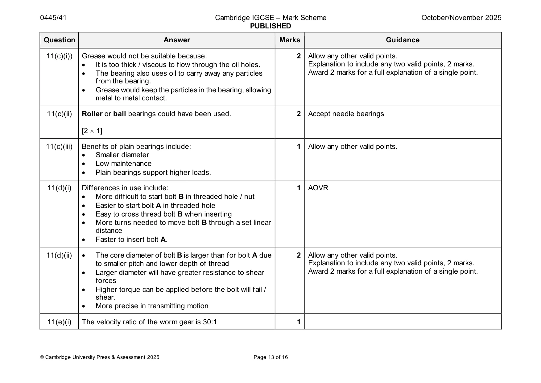
Mark scheme: 11(a)(i) Other types of belt could be flat, toothed or round. 2 Accept ‘plain belt’. Sketches must be identified with a name for mark to be [2 1] awarded. 11(a)(ii) Reasons for the vee belt being most suitable are: 2 Allow any other valid points. • Transmit power very well Explanation to include any two valid points, 2 marks. • Limited slip between belt and pulleys / high friction force Award 2 marks for a full explanation of a single point. • Low noise and vibration levels • Easy to install and maintain. 11(b)(i) The vee pulley transfers motion to the crankshaft causing it 4 1 mark for each word correctly used to rotate. This in turn causes the connecting rod to move the piston . [4 1] 11(b)(ii) Crank [1] / slider [1] mechanism. 2 11(b)(iii) Area of piston = Π r2 = 3.142 252 = 1963.75 (1963.495 on 3 Award 3 marks for correct answer with no working. calculator) [1] Throw of piston = 12.5 2 = 25 [1] Volume displaced = 1963.75 25 = 49093.75 mm3 or 49 087.39 [1] 11(c)(i)) Grease would not be suitable because: 2 Allow any other valid points. • It is too thick / viscous to flow through the oil holes. Explanation to include any two valid points, 2 marks. • The bearing also uses oil to carry away any particles Award 2 marks for a full explanation of a single point. from the bearing. • Grease would keep the particles in the bearing, allowing metal to metal contact. 11(c)(ii) Roller or ball bearings could have been used. 2 Accept needle bearings [2 1] 11(c)(iii) Benefits of plain bearings include: 1 Allow any other valid points. • Smaller diameter • Low maintenance • Plain bearings support higher loads. 11(d)(i) Differences in use include: 1 AOVR • More difficult to start bolt B in threaded hole / nut • Easier to start bolt A in threaded hole • Easy to cross thread bolt B when inserting • More turns needed to move bolt B through a set linear distance • Faster to insert bolt A. 11(d)(ii) • The core diameter of bolt B is larger than for bolt A due 2 Allow any other valid points. to smaller pitch and lower depth of thread Explanation to include any two valid points, 2 marks. • Larger diameter will have greater resistance to shear Award 2 marks for a full explanation of a single point. forces • Higher torque can be applied before the bolt will fail / shear. • More precise in transmitting motion 11(e)(i) The velocity ratio of the worm gear is 30:1 1 11(e)(ii) Worm gear ratio 30:1 15 t:40 t ratio 2.666:1 [1] 3 Allow ecf from (d)(ii). Total reduction ratio = 30 2.666 = 80:1 [1] Speed of 40 t gear = 850 / 80 = 10.625 rpm [1] Award 3 marks for correct answer with no working.
Q12 · Complete Table 12.1 by adding ticks (3) to identify the type of material
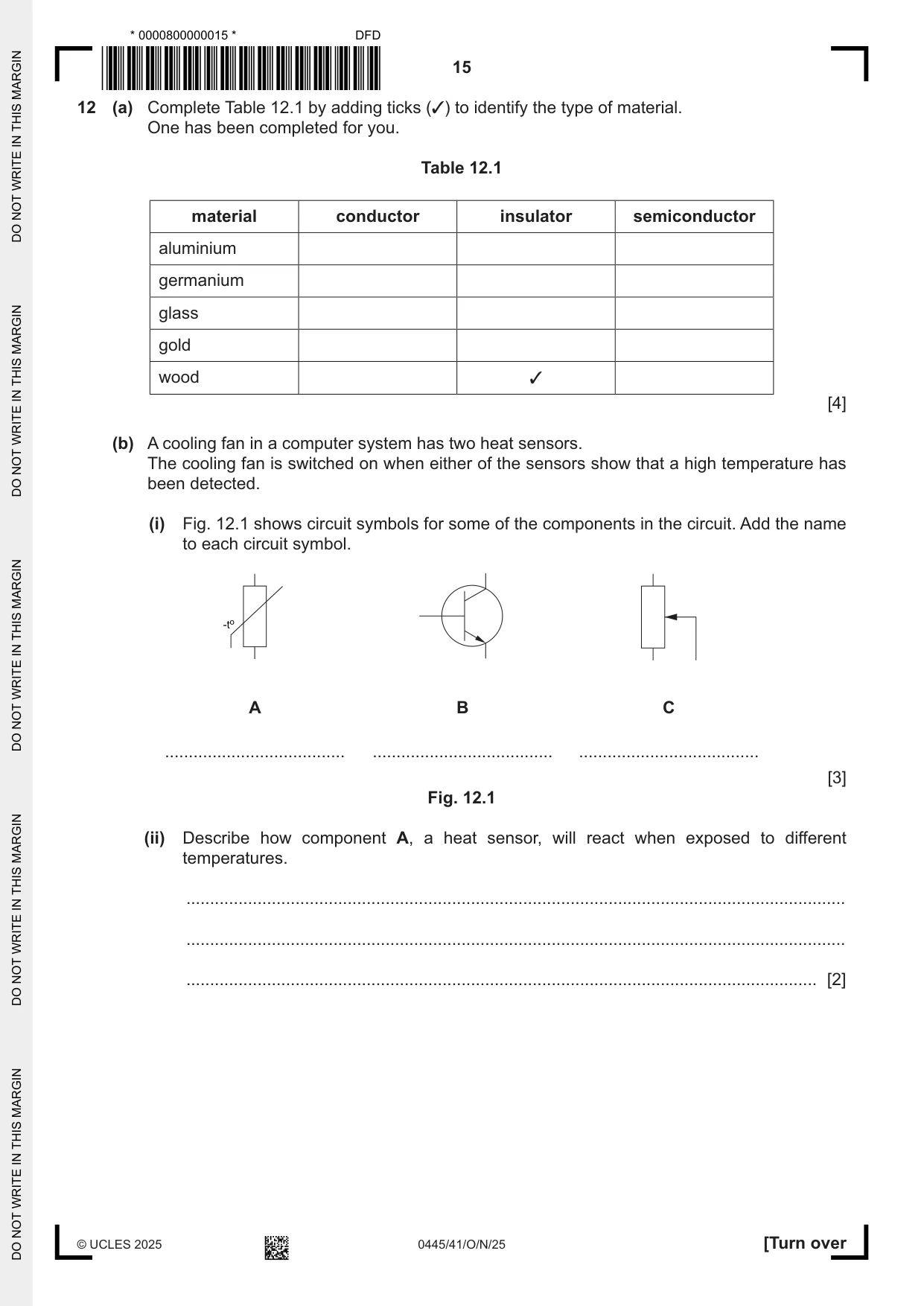
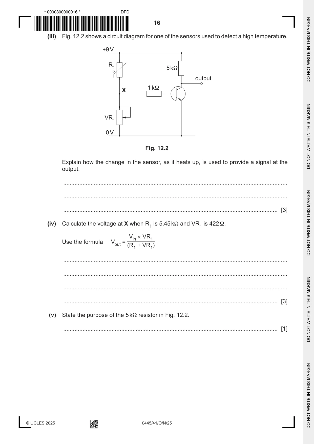
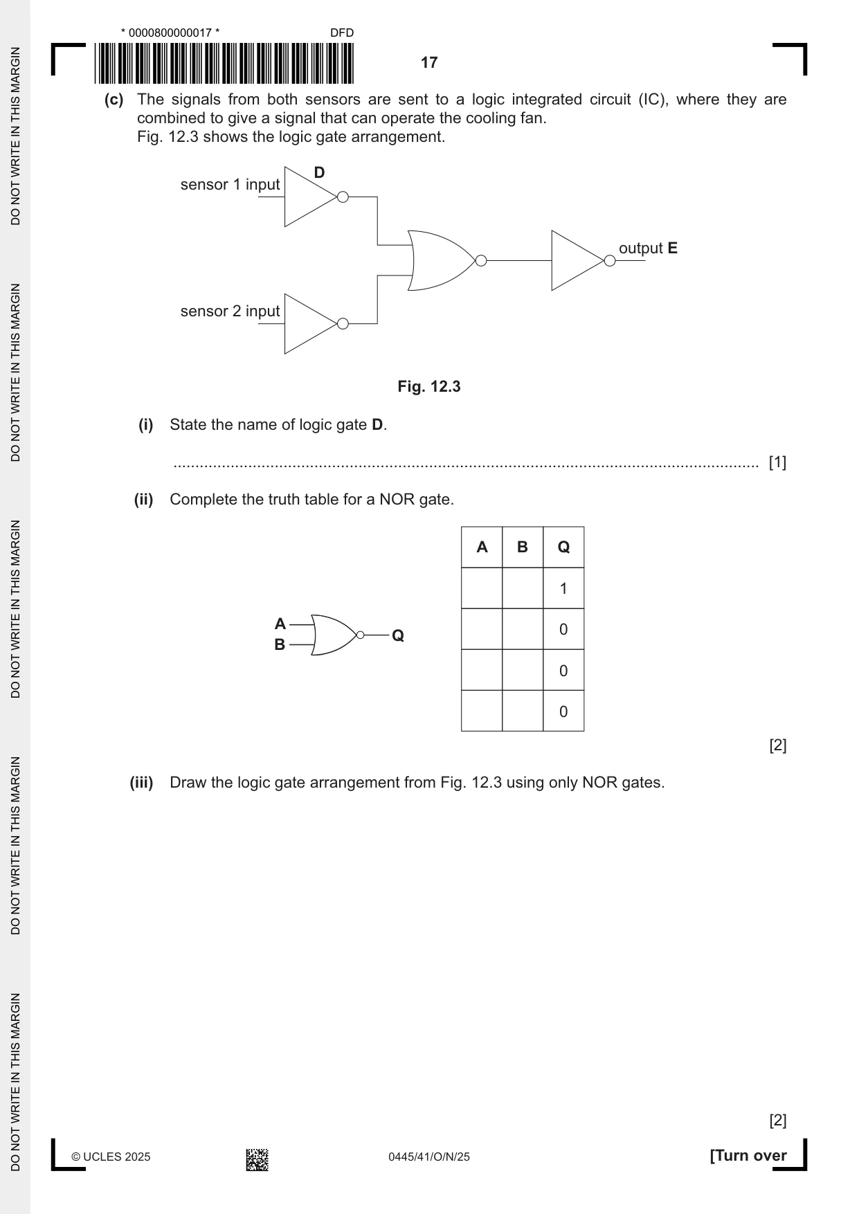
12 (a) Complete Table 12.1 by adding ticks (3) to identify the type of material. One has been completed for you. Table 12.1 material conductor insulator semiconductor aluminium germanium glass gold wood 3 [4] (b) A cooling fan in a computer system has two heat sensors. The cooling fan is switched on when either of the sensors show that a high temperature has been detected. (i) Fig. 12.1 shows circuit symbols for some of the components in the circuit. Add the name to each circuit symbol. A B C ...................................... ...................................... ...................................... [3] Fig. 12.1 (ii) Describe how component A, a heat sensor, will react when exposed to different temperatures. ........................................................................................................................................... ........................................................................................................................................... ..................................................................................................................................... [2] (iii) Fig. 12.2 shows a circuit diagram for one of the sensors used to detect a high temperature. +9 V R1 5 kΩ output 1 kΩ X VR1 0 V Fig. 12.2 Explain how the change in the sensor, as it heats up, is used to provide a signal at the output. ........................................................................................................................................... ........................................................................................................................................... ..................................................................................................................................... [3] (iv) Calculate the voltage at X when R1 is 5.45 kΩ and VR1 is 422 Ω. Vin × VR1 Use the formula Vout = + (R1 VR1) ........................................................................................................................................... ........................................................................................................................................... ........................................................................................................................................... ..................................................................................................................................... [3] (v) State the purpose of the 5 kΩ resistor in Fig. 12.2. ..................................................................................................................................... [1] (c) The signals from both sensors are sent to a logic integrated circuit (IC), where they are combined to give a signal that can operate the cooling fan. Fig. 12.3 shows the logic gate arrangement. D sensor 1 input output E sensor 2 input Fig. 12.3 (i) State the name of logic gate D. ..................................................................................................................................... [1] (ii) Complete the truth table for a NOR gate. A B Q 1 A 0 Q B 0 0 [2] (iii) Draw the logic gate arrangement from Fig. 12.3 using only NOR gates. [2]
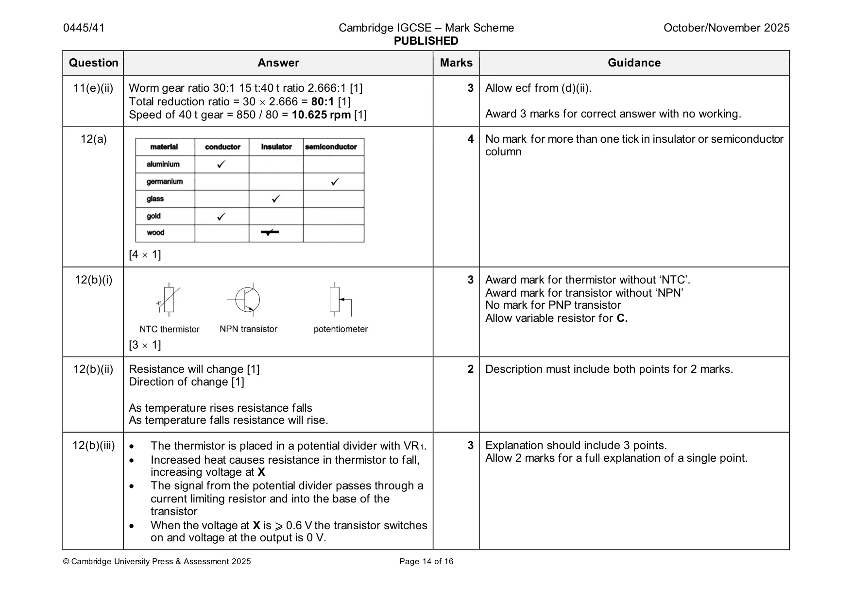
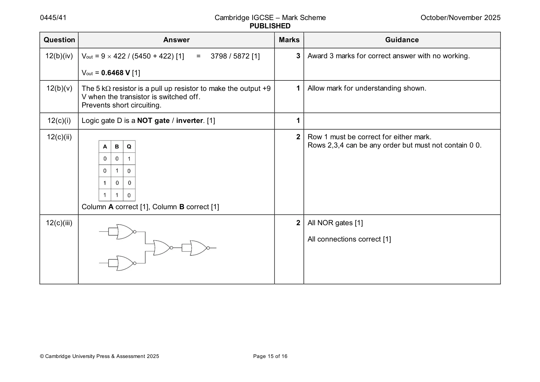
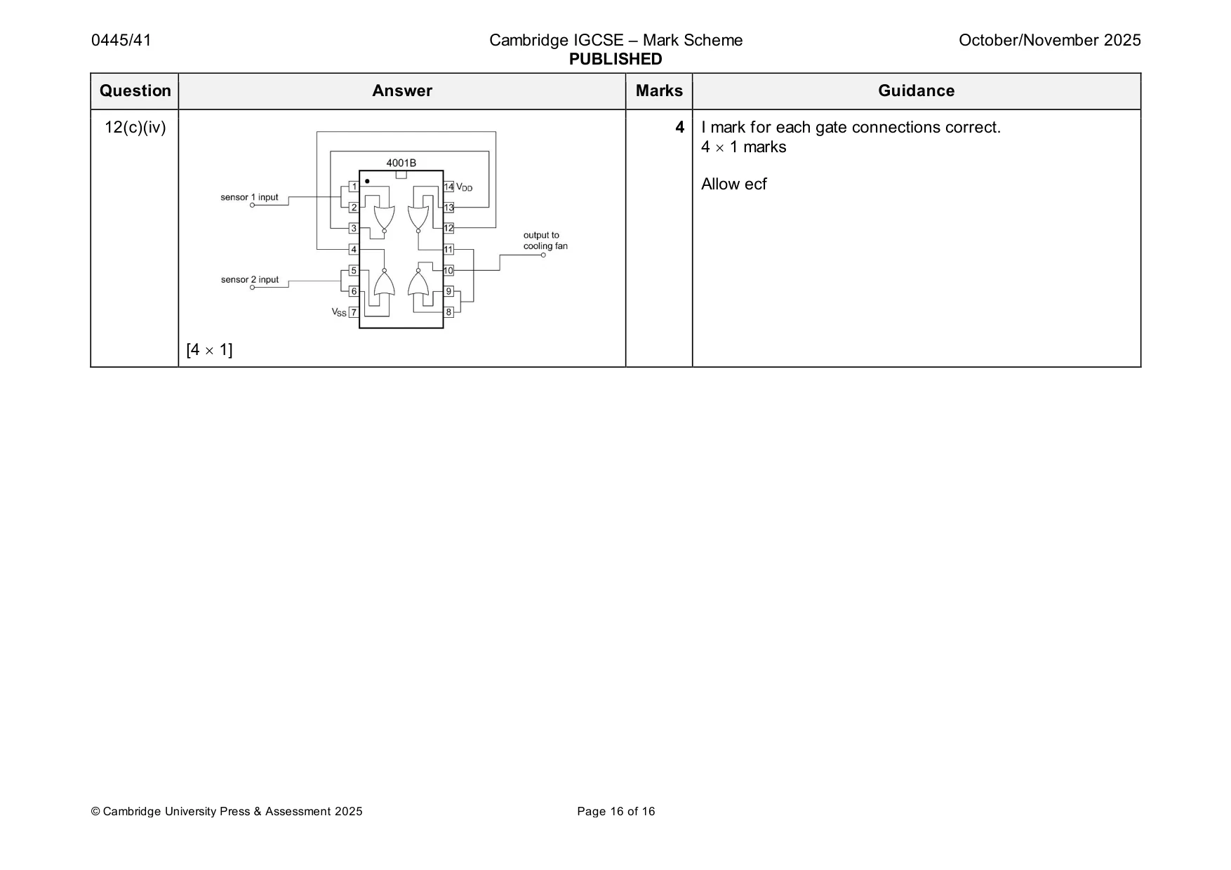
Mark scheme: 12(a) 4 No mark for more than one tick in insulator or semiconductor column [4 1] 12(b)(i) 3 Award mark for thermistor without ‘NTC’. Award mark for transistor without ‘NPN’ No mark for PNP transistor Allow variable resistor for C. [3 1] 12(b)(ii) Resistance will change [1] 2 Description must include both points for 2 marks. Direction of change [1] As temperature rises resistance falls As temperature falls resistance will rise. 12(b)(iii) • The thermistor is placed in a potential divider with VR1. 3 Explanation should include 3 points. • Increased heat causes resistance in thermistor to fall, Allow 2 marks for a full explanation of a single point. increasing voltage at X • The signal from the potential divider passes through a current limiting resistor and into the base of the transistor • When the voltage at X is ⩾ 0.6 V the transistor switches on and voltage at the output is 0 V. 12(b)(iv) Vout = 9 422 / (5450 + 422) [1] = 3798 / 5872 [1] 3 Award 3 marks for correct answer with no working. Vout = 0.6468 V [1] 12(b)(v) The 5 k resistor is a pull up resistor to make the output +9 1 Allow mark for understanding shown. V when the transistor is switched off. Prevents short circuiting. 12(c)(i) Logic gate D is a NOT gate / inverter. [1] 1 12(c)(ii) 2 Row 1 must be correct for either mark. Rows 2,3,4 can be any order but must not contain 0 0. Column A correct [1], Column B correct [1] 12(c)(iii) 2 All NOR gates [1] All connections correct [1] 12(c)(iv) 4 I mark for each gate connections correct. 4 1 marks Allow ecf [4 1]
What was in this paper
The subtopics covered by these 12 questions, and how many questions each got. Open one in a new tab to see every Cambridge question on it.
What you needed in this session
Cambridge’s own grade thresholds for 2025 Oct/Nov, Paper 4 · Variant 1. A higher threshold means an easier paper — the bar moves with how the cohort did.