Cambridge IGCSE Design and Technology 0445 — 2019 May/June Paper 4 · Variant 3
0445/43/M/J/19 · 11 questions · 50 marks · ≈56 min
The question paper and its mark scheme, free to read here and free to download. This is Cambridge’s own paper, exactly as it was sat.
Question paper24 pages




Mark scheme12 pages
Answers below. Sit the paper first if you are practising.
Questions as text
Q1 · Safety symbols that could be found in a workshop
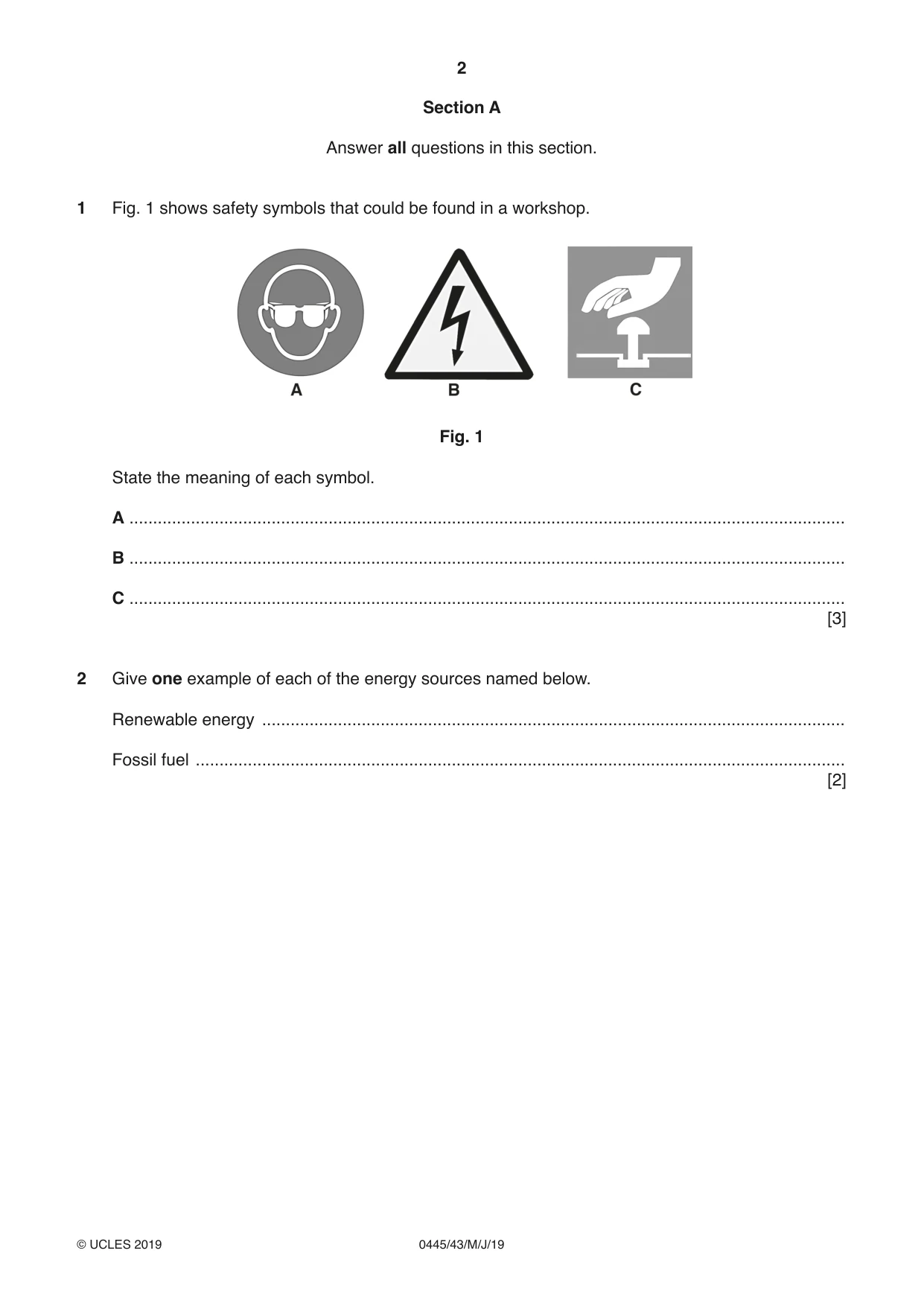
1 Fig. 1 shows safety symbols that could be found in a workshop. Fig. 1 State the meaning of each symbol. A ....................................................................................................................................................... B ....................................................................................................................................................... C ....................................................................................................................................................... [3]
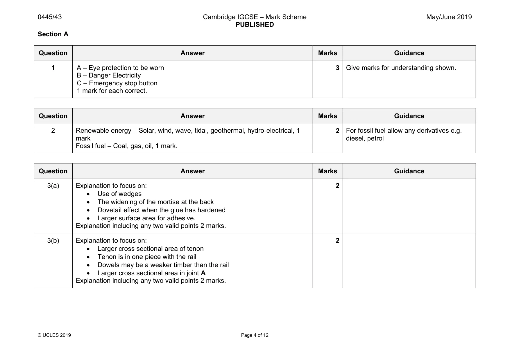
Mark scheme: 1 A – Eye protection to be worn B – Danger Electricity C – Emergency stop button 1 mark for each correct. 3
Q2 · Give one example of each of the energy sources named below
2 Give one example of each of the energy sources named below. Renewable energy ........................................................................................................................... Fossil fuel ......................................................................................................................................... [2]
Mark scheme: 2 Renewable energy – Solar, wind, wave, tidal, geothermal, hydro-electrical, 1 mark Fossil fuel – Coal, gas, oil, 1 mark. 2 For fossil fuel allow any derivatives e.g. diesel, petrol
Q3 · Two types of joint that can be used for joining a chair rail to a leg
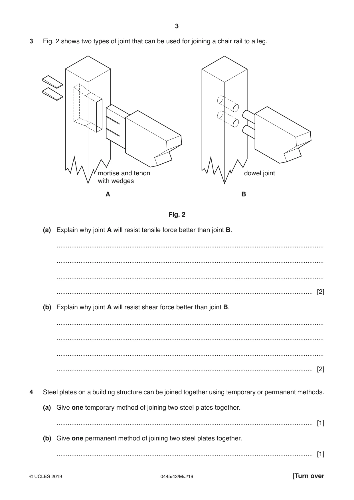
3 Fig. 2 shows two types of joint that can be used for joining a chair rail to a leg. mortise and tenon dowel joint with wedges A B Fig. 2 (a) Explain why joint A will resist tensile force better than joint B. ................................................................................................................................................... ................................................................................................................................................... ................................................................................................................................................... ............................................................................................................................................. [2] (b) Explain why joint A will resist shear force better than joint B. ................................................................................................................................................... ................................................................................................................................................... ................................................................................................................................................... ............................................................................................................................................. [2]
Mark scheme: 3(a) Explanation to focus on: • Use of wedges • The widening of the mortise at the back • Dovetail effect when the glue has hardened • Larger surface area for adhesive. Explanation including any two valid points 2 marks. 2 3(b) Explanation to focus on: • Larger cross sectional area of tenon • Tenon is in one piece with the rail • Dowels may be a weaker timber than the rail • Larger cross sectional area in joint A Explanation including any two valid points 2 marks. 2
Q4 · Steel plates on a building structure can be joined together using temporary or permanent…
4 Steel plates on a building structure can be joined together using temporary or permanent methods. (a) Give one temporary method of joining two steel plates together. ............................................................................................................................................. [1] (b) Give one permanent method of joining two steel plates together. ............................................................................................................................................. [1]
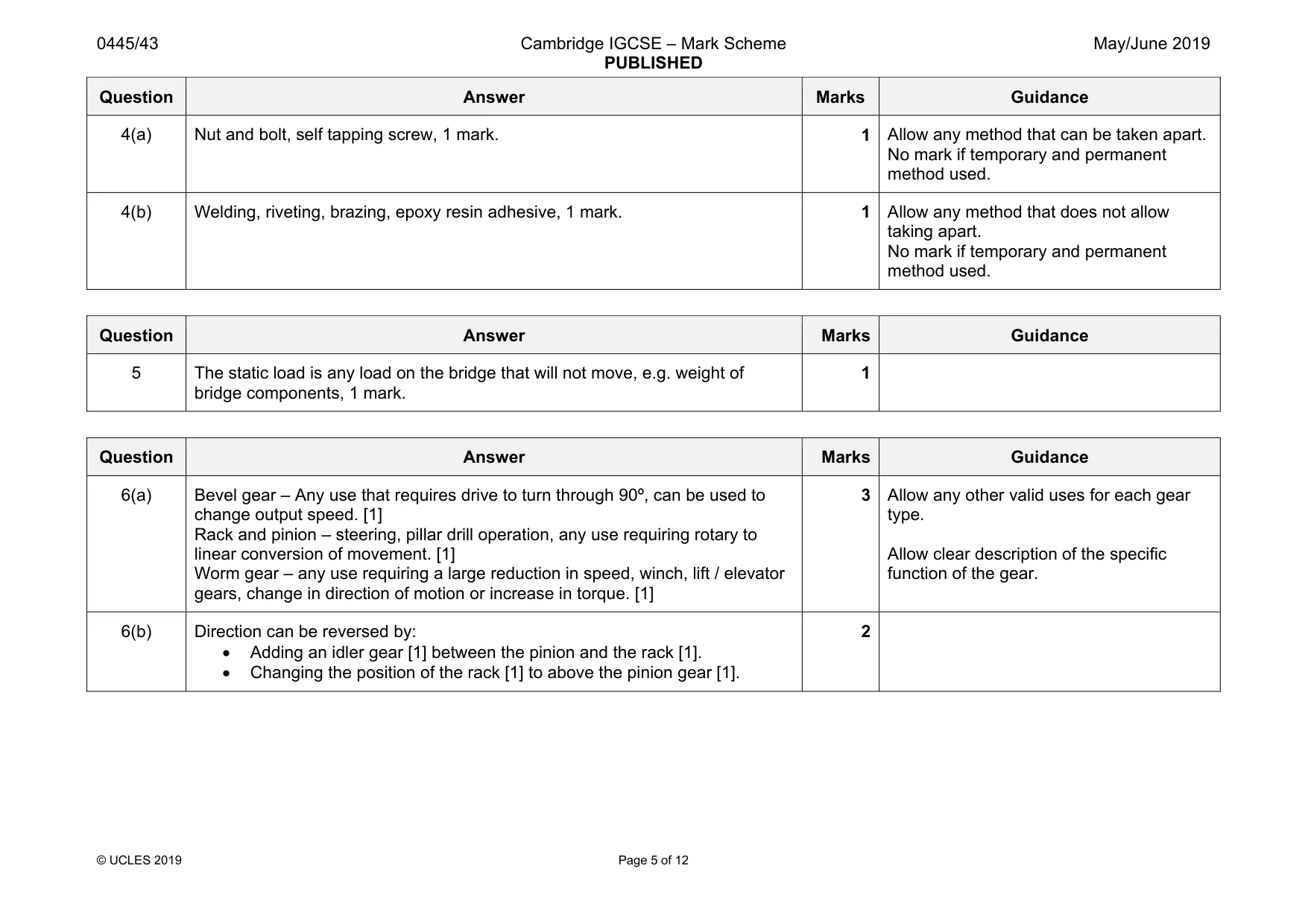
Mark scheme: 4(a) Nut and bolt, self tapping screw, 1 mark. 1 Allow any method that can be taken apart. No mark if temporary and permanent method used. 4(b) Welding, riveting, brazing, epoxy resin adhesive, 1 mark. 1 Allow any method that does not allow taking apart. No mark if temporary and permanent method used.
Q5 · State what is meant by ‘static load’ on a bridge
5 State what is meant by ‘static load’ on a bridge. .................................................................................................................................................... [1]
Mark scheme: 5 The static load is any load on the bridge that will not move, e.g. weight of bridge components, 1 mark. 1
Q6 · Give one specific use for each of the following types of gear
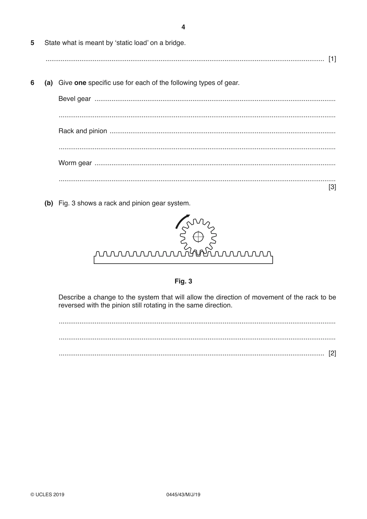
6 (a) Give one specific use for each of the following types of gear. Bevel gear ................................................................................................................................ ................................................................................................................................................... Rack and pinion ........................................................................................................................ ................................................................................................................................................... Worm gear ................................................................................................................................ ................................................................................................................................................... [3] (b) Fig. 3 shows a rack and pinion gear system. Fig. 3 Describe a change to the system that will allow the direction of movement of the rack to be reversed with the pinion still rotating in the same direction. ................................................................................................................................................... ................................................................................................................................................... ............................................................................................................................................. [2]
Mark scheme: 6(a) Bevel gear – Any use that requires drive to turn through 90º, can be used to change output speed. [1] Rack and pinion – steering, pillar drill operation, any use requiring rotary to linear conversion of movement. [1] Worm gear – any use requiring a large reduction in speed, winch, lift / elevator gears, change in direction of motion or increase in torque. [1] 3 type. Allow clear description of the specific function of the gear. 6(b) Direction can be reversed by: • Adding an idler gear [1] between the pinion and the rack [1]. • Changing the position of the rack [1] to above the pinion gear [1]. 2
Q7 · Use sketches and notes to show what is meant by a compound gear arrangement
7 Use sketches and notes to show what is meant by a compound gear arrangement. [2]
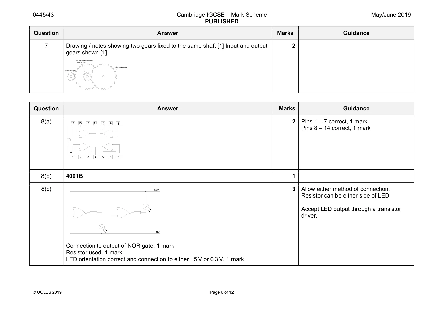
Mark scheme: 7 Drawing / notes showing two gears fixed to the same shaft [1] Input and output gears shown [1]. 2 input/driver gear output/driven gear two gears fixed together on single shaft
Q8 · The outline of an IC
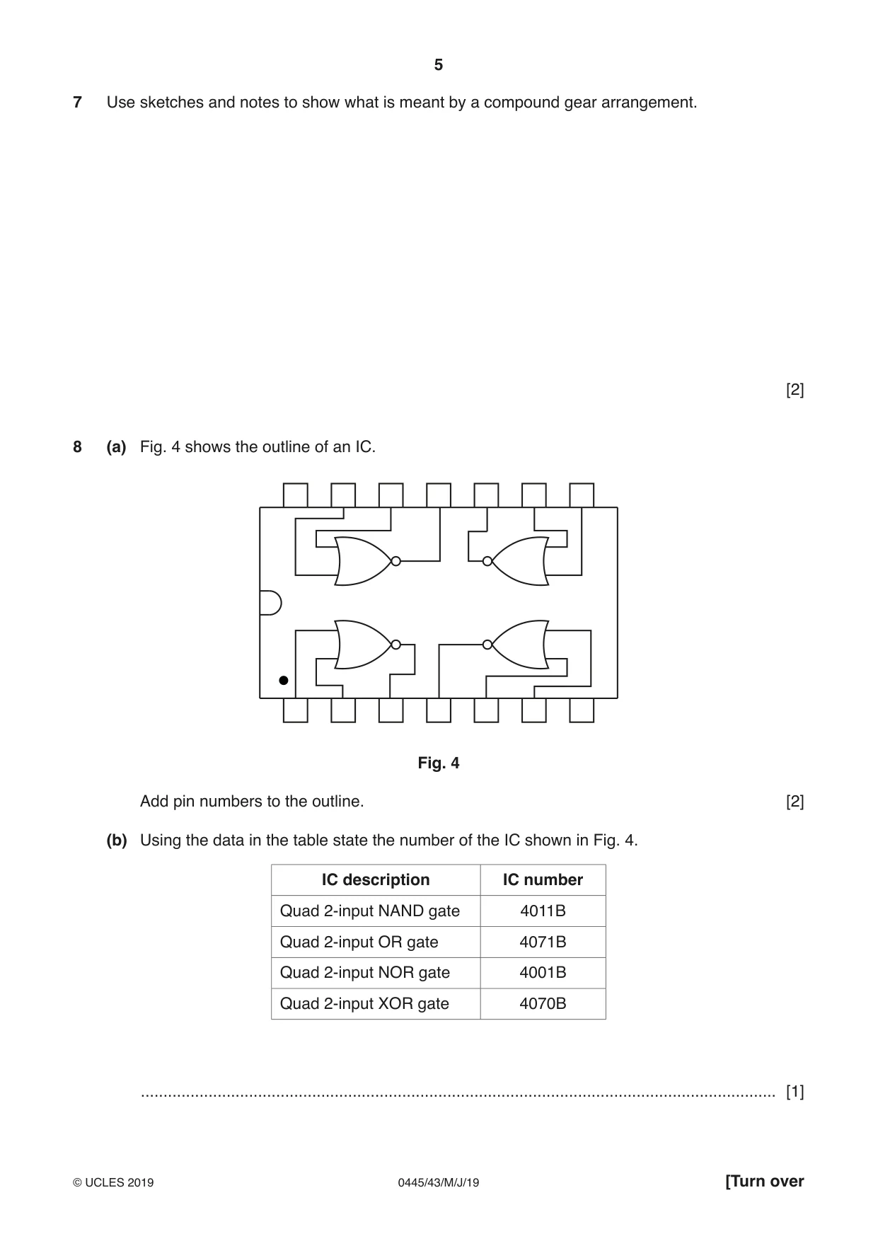
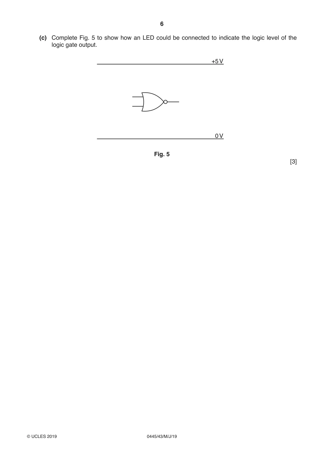
8 (a) Fig. 4 shows the outline of an IC. Fig. 4 Add pin numbers to the outline. [2] (b) Using the data in the table state the number of the IC shown in Fig. 4. IC description IC number Quad 2-input NAND gate 4011B Quad 2-input OR gate 4071B Quad 2-input NOR gate 4001B Quad 2-input XOR gate 4070B ............................................................................................................................................. [1] (c) Complete Fig. 5 to show how an LED could be connected to indicate the logic level of the logic gate output. +5 V 0 V Fig. 5 [3]
Mark scheme: 8(a) 2 Pins 1 – 7 correct, 1 mark Pins 8 – 14 correct, 1 mark 8(b) 4001B 1 8(c) Connection to output of NOR gate, 1 mark Resistor used, 1 mark LED orientation correct and connection to either +5 V or 0 3 V, 1 mark 3 Allow either method of connection. Resistor can be either side of LED Accept LED output through a transistor driver. 1 2 3 4 5 6 7 8 9 10 11 12 13 14 +5V 0V
Q9 · A model truss bridge that has been made in a school to span a 270 mm gap
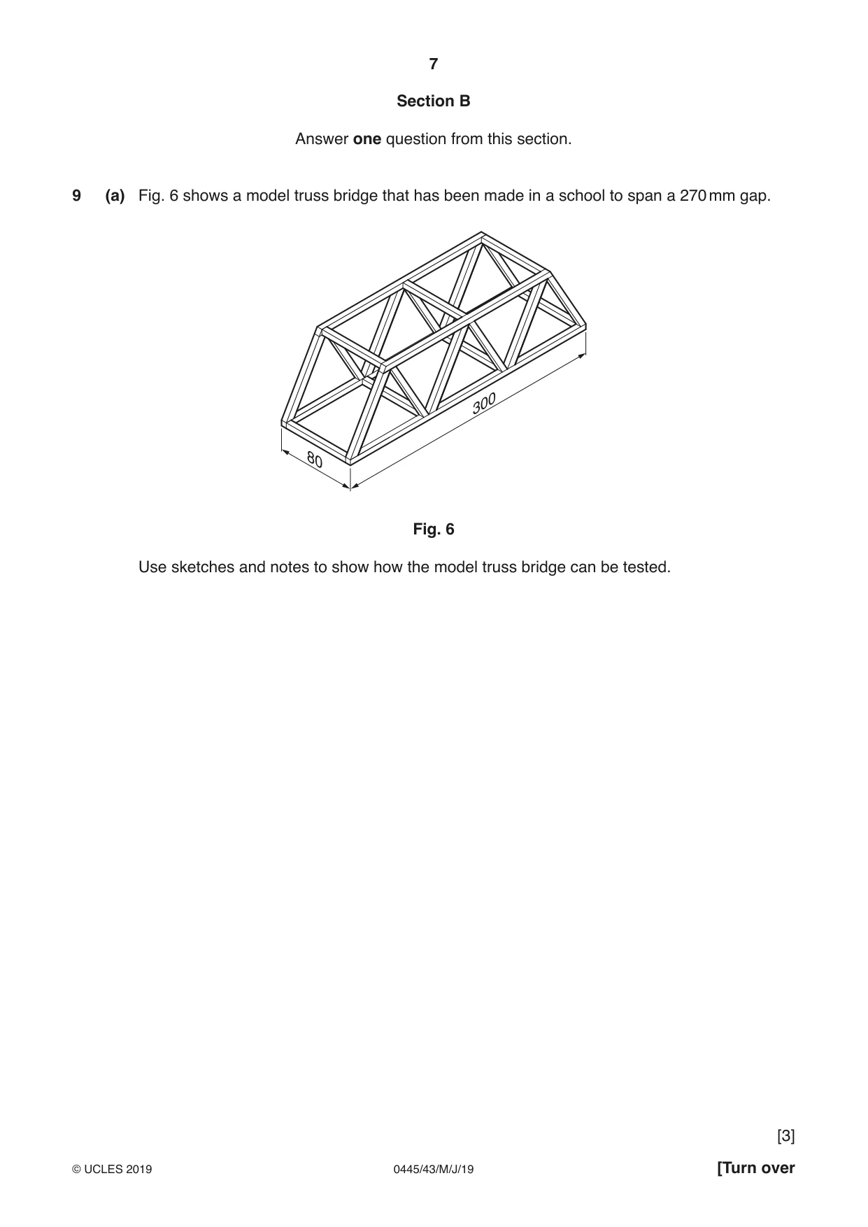
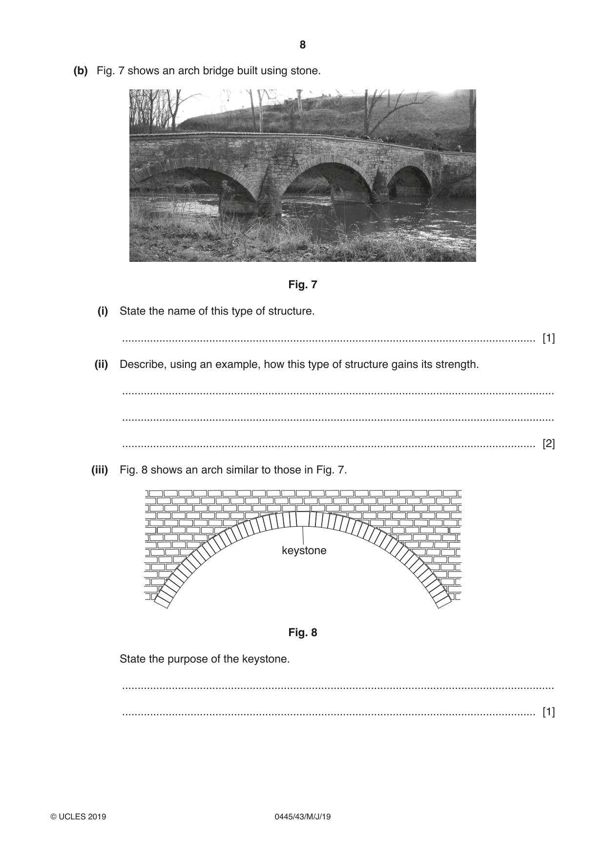
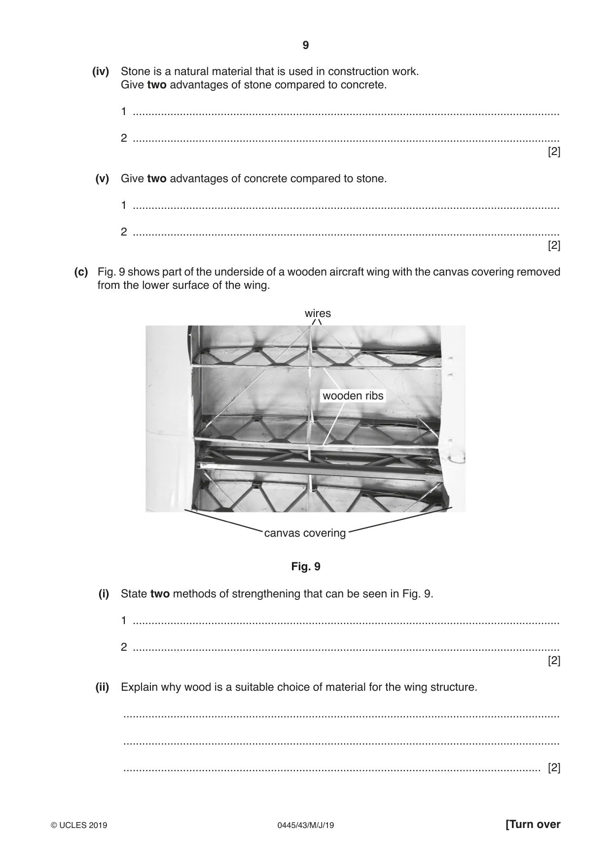
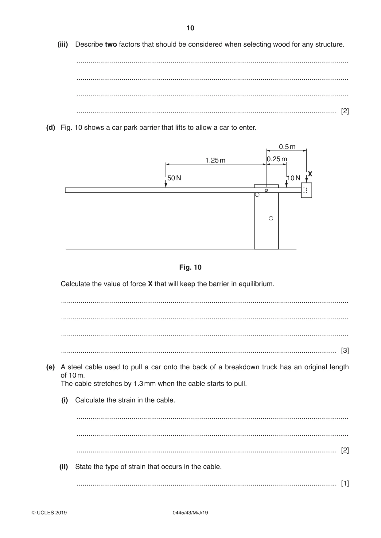
9 (a) Fig. 6 shows a model truss bridge that has been made in a school to span a 270 mm gap. 300 80 Fig. 6 Use sketches and notes to show how the model truss bridge can be tested. [3] (b) Fig. 7 shows an arch bridge built using stone. Fig. 7 (i) State the name of this type of structure. ..................................................................................................................................... [1] (ii) Describe, using an example, how this type of structure gains its strength. ........................................................................................................................................... ........................................................................................................................................... ..................................................................................................................................... [2] (iii) Fig. 8 shows an arch similar to those in Fig. 7. keystone Fig. 8 State the purpose of the keystone. ........................................................................................................................................... ..................................................................................................................................... [1] (iv) Stone is a natural material that is used in construction work. Give two advantages of stone compared to concrete. 1 ........................................................................................................................................ 2 ........................................................................................................................................ [2] (v) Give two advantages of concrete compared to stone. 1 ........................................................................................................................................ 2 ........................................................................................................................................ [2] (c) Fig. 9 shows part of the underside of a wooden aircraft wing with the canvas covering removed from the lower surface of the wing. wires wooden ribs canvas covering Fig. 9 (i) State two methods of strengthening that can be seen in Fig. 9. 1 ........................................................................................................................................ 2 ........................................................................................................................................ [2] (ii) Explain why wood is a suitable choice of material for the wing structure. ........................................................................................................................................... ........................................................................................................................................... ..................................................................................................................................... [2] (iii) Describe two factors that should be considered when selecting wood for any structure. ........................................................................................................................................... ........................................................................................................................................... ........................................................................................................................................... ..................................................................................................................................... [2] (d) Fig. 10 shows a car park barrier that lifts to allow a car to enter. 0.5 m 1.25 m 0.25 m X 50 N 10 N Fig. 10 Calculate the value of force X that will keep the barrier in equilibrium. ................................................................................................................................................... ................................................................................................................................................... ................................................................................................................................................... ............................................................................................................................................. [3] (e) A steel cable used to pull a car onto the back of a breakdown truck has an original length of 10 m. The cable stretches by 1.3 mm when the cable starts to pull. (i) Calculate the strain in the cable. ........................................................................................................................................... ........................................................................................................................................... ..................................................................................................................................... [2] (ii) State the type of strain that occurs in the cable. ..................................................................................................................................... [1] (iii) The ‘elastic limit’ of the cable is important to the manufacturer when deciding the maximum load that can be placed on the cable. Explain what is meant by elastic limit. ........................................................................................................................................... ........................................................................................................................................... ..................................................................................................................................... [2]
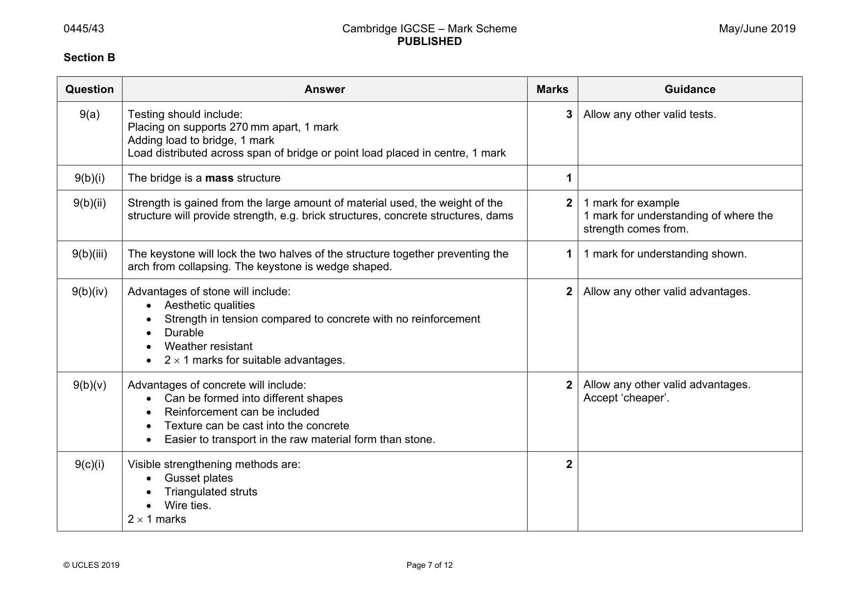
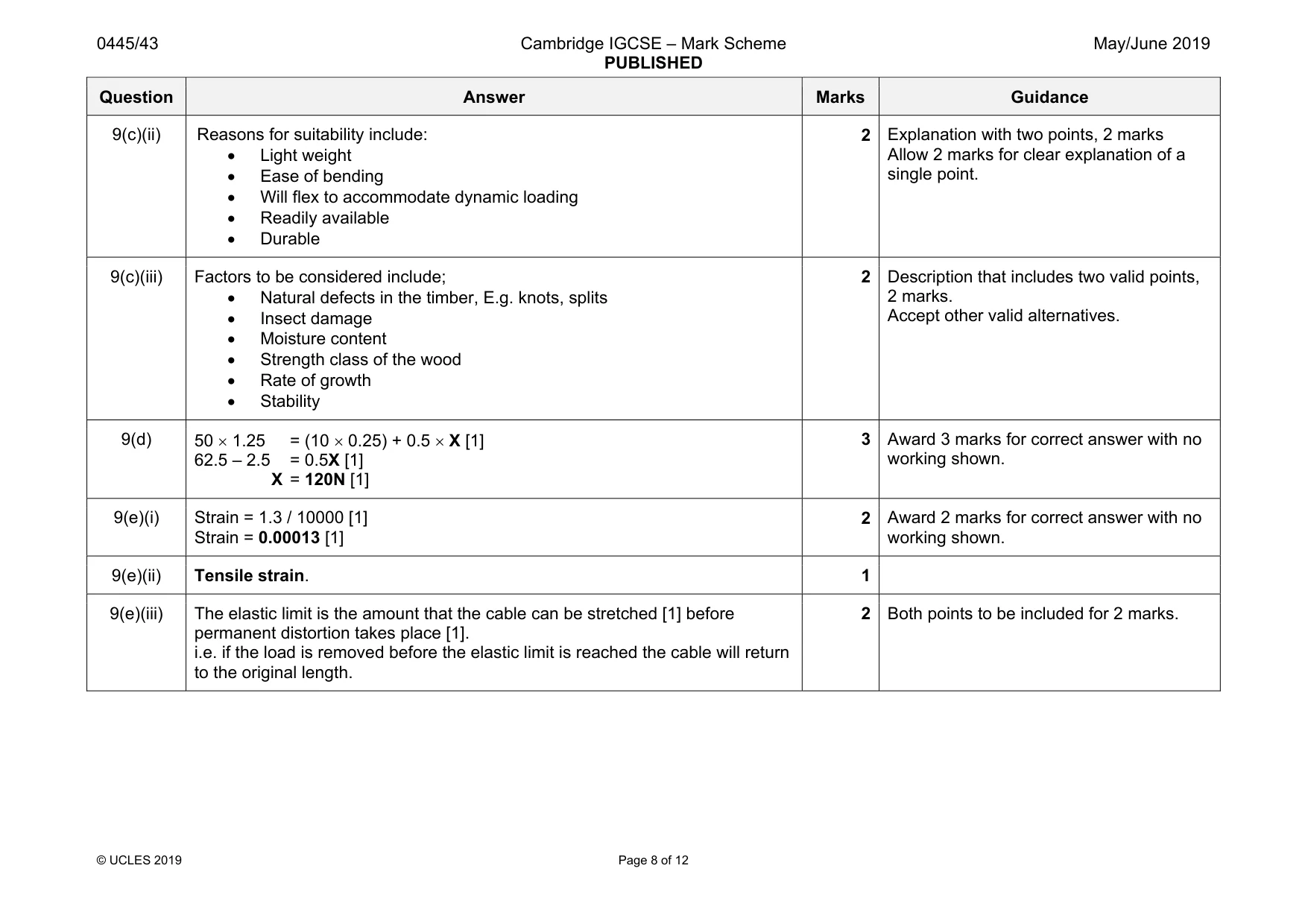
Mark scheme: 9(a) Testing should include: Placing on supports 270 mm apart, 1 mark Adding load to bridge, 1 mark Load distributed across span of bridge or point load placed in centre, 1 mark 3 9(b)(i) The bridge is a mass structure 1 9(b)(ii) Strength is gained from the large amount of material used, the weight of the structure will provide strength, e.g. brick structures, concrete structures, dams 2 1 mark for example 1 mark for understanding of where the strength comes from. 9(b)(iii) The keystone will lock the two halves of the structure together preventing the arch from collapsing. The keystone is wedge shaped. 1 1 mark for understanding shown. 9(b)(iv) Advantages of stone will include: • Aesthetic qualities • Strength in tension compared to concrete with no reinforcement • Durable • Weather resistant • 2 × 1 marks for suitable advantages. 2 Allow any other valid advantages. 9(b)(v) Advantages of concrete will include: • Can be formed into different shapes • Reinforcement can be included • Texture can be cast into the concrete • Easier to transport in the raw material form than stone. 2 Allow any other valid advantages. Accept ‘cheaper’. 9(c)(i) Visible strengthening methods are: • Gusset plates • Triangulated struts • Wire ties. 2 × 1 marks 2 Question Answer Marks Guidance 9(c)(ii) Reasons for suitability include: • Light weight • Ease of bending • Will flex to accommodate dynamic loading • Readily available • Durable 2 Explanation with two points, 2 marks Allow 2 marks for clear explanation of a single point. 9(c)(iii) Factors to be considered include; • Natural defects in the timber, E.g. knots, splits • Insect damage • Moisture content • Strength class of the wood • Rate of growth • Stability 2 Description that includes two valid points, 2 marks. Accept other valid alternatives. 9(d) 50 × 1.25 = (10 × 0.25) + 0.5 × X [1] 62.5 – 2.5 = 0.5X [1] X = 120N [1] 3 Award 3 marks for correct answer with no working shown. 9(e)(i) Strain = 1.3 / 10000 [1] Strain = 0.00013 [1] 2 Award 2 marks for correct answer with no working shown. 9(e)(ii) Tensile strain. 1 9(e)(iii) The elastic limit is the amount that the cable can be stretched [1] before permanent distortion takes place [1]. i.e. if the load is removed before the elastic limit is reached the cable will return to the original length. 2 Both points to be included for 2 marks.
Q10 · A ‘sit-on’ toy digger for a child
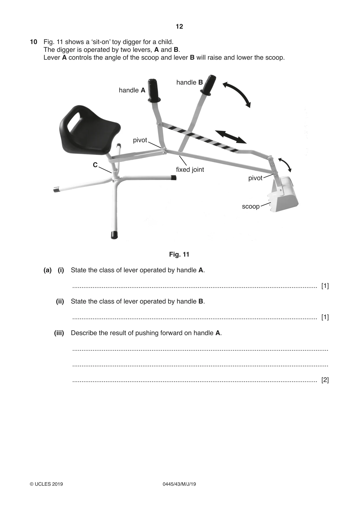
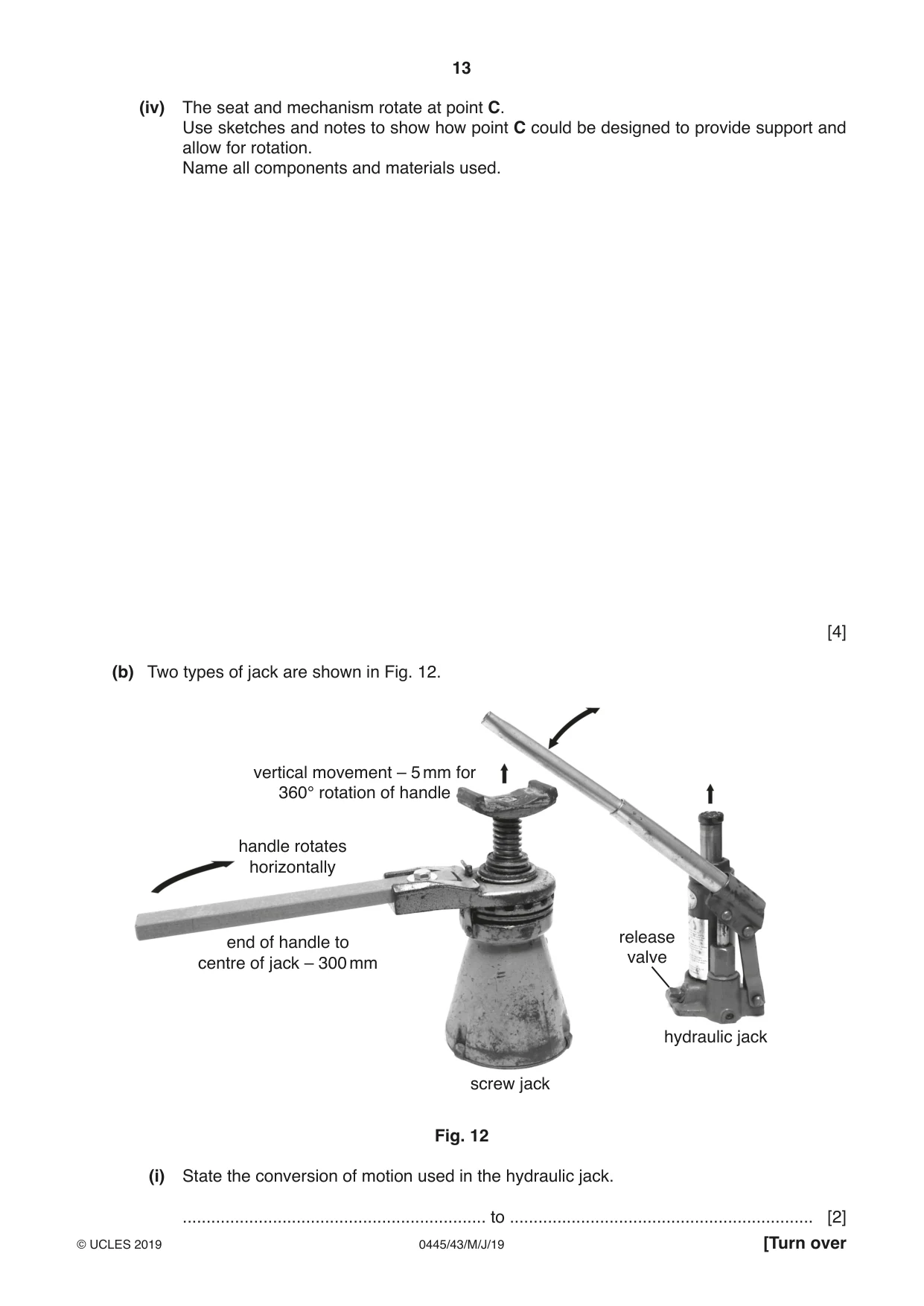
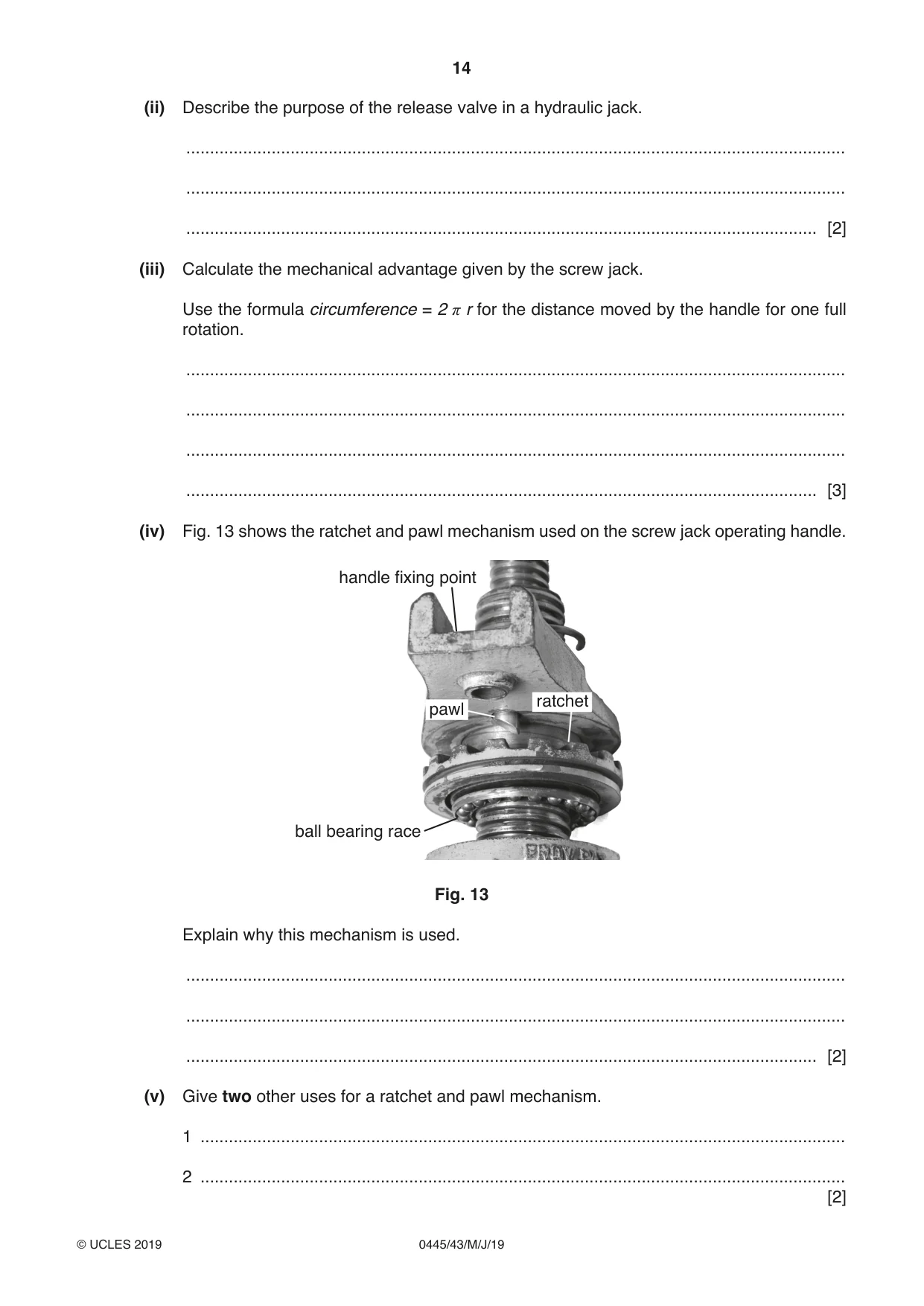
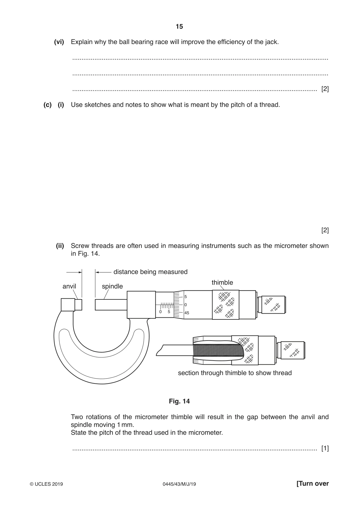
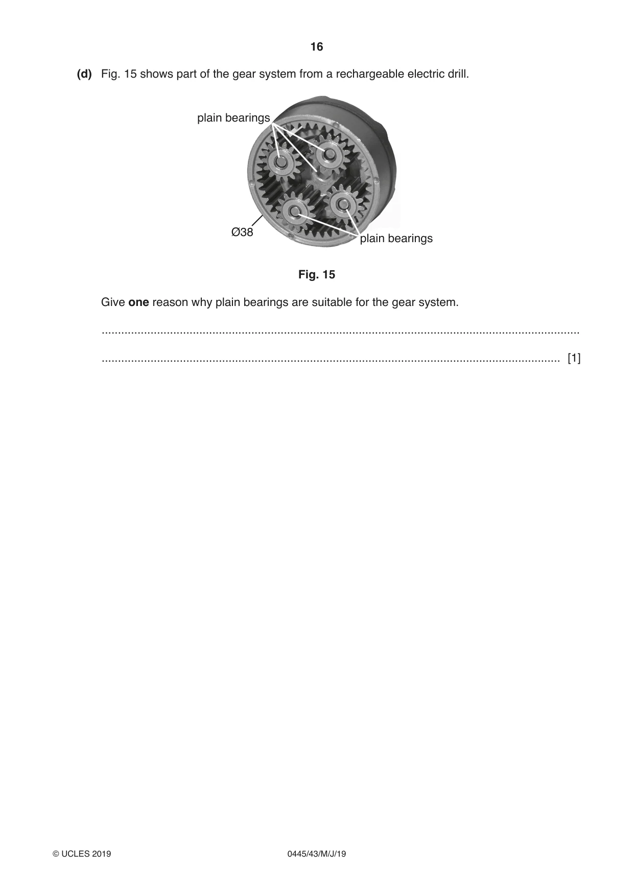
10 Fig. 11 shows a ‘sit-on’ toy digger for a child. The digger is operated by two levers, A and B. Lever A controls the angle of the scoop and lever B will raise and lower the scoop. handle B handle A pivot C fixed joint pivot scoop Fig. 11 (a) (i) State the class of lever operated by handle A. ..................................................................................................................................... [1] (ii) State the class of lever operated by handle B. ..................................................................................................................................... [1] (iii) Describe the result of pushing forward on handle A. ........................................................................................................................................... ........................................................................................................................................... ..................................................................................................................................... [2] (iv) The seat and mechanism rotate at point C. Use sketches and notes to show how point C could be designed to provide support and allow for rotation. Name all components and materials used. [4] (b) Two types of jack are shown in Fig. 12. vertical movement – 5 mm for 360° rotation of handle handle rotates horizontally release end of handle to valve centre of jack – 300 mm hydraulic jack screw jack Fig. 12 (i) State the conversion of motion used in the hydraulic jack. ................................................................ to ................................................................ [2] (ii) Describe the purpose of the release valve in a hydraulic jack. ........................................................................................................................................... ........................................................................................................................................... ..................................................................................................................................... [2] (iii) Calculate the mechanical advantage given by the screw jack. Use the formula circumference = 2 π r for the distance moved by the handle for one full rotation. ........................................................................................................................................... ........................................................................................................................................... ........................................................................................................................................... ..................................................................................................................................... [3] (iv) Fig. 13 shows the ratchet and pawl mechanism used on the screw jack operating handle. handle fixing point ratchet pawl ball bearing race Fig. 13 Explain why this mechanism is used. ........................................................................................................................................... ........................................................................................................................................... ..................................................................................................................................... [2] (v) Give two other uses for a ratchet and pawl mechanism. 1 ........................................................................................................................................ 2 ........................................................................................................................................ [2] (vi) Explain why the ball bearing race will improve the efficiency of the jack. ........................................................................................................................................... ........................................................................................................................................... ..................................................................................................................................... [2] (c) (i) Use sketches and notes to show what is meant by the pitch of a thread. [2] (ii) Screw threads are often used in measuring instruments such as the micrometer shown in Fig. 14. distance being measured thimble anvil spindle 5 0 0 5 45 section through thimble to show thread Fig. 14 Two rotations of the micrometer thimble will result in the gap between the anvil and spindle moving 1 mm. State the pitch of the thread used in the micrometer. ..................................................................................................................................... [1] (d) Fig. 15 shows part of the gear system from a rechargeable electric drill. plain bearings Ø38 plain bearings Fig. 15 Give one reason why plain bearings are suitable for the gear system. ................................................................................................................................................... ............................................................................................................................................. [1]
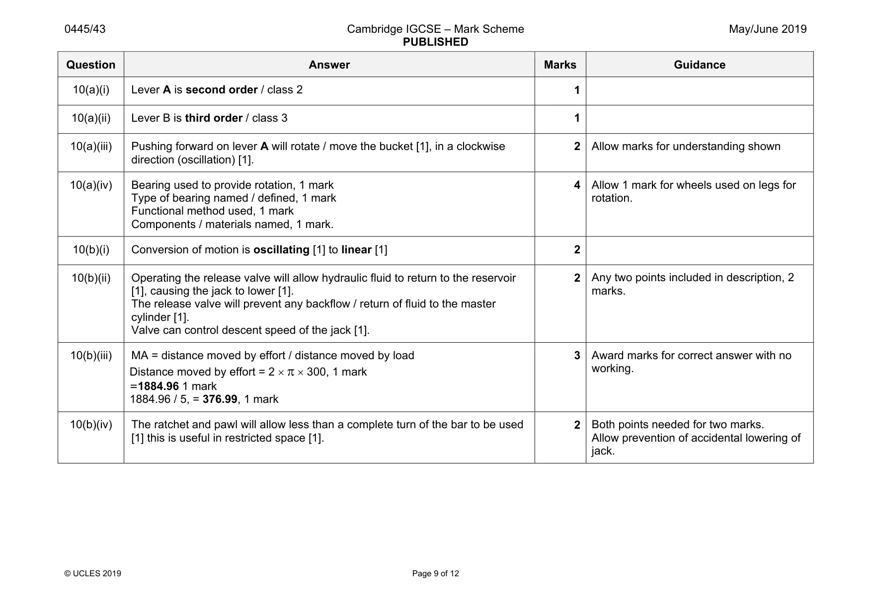
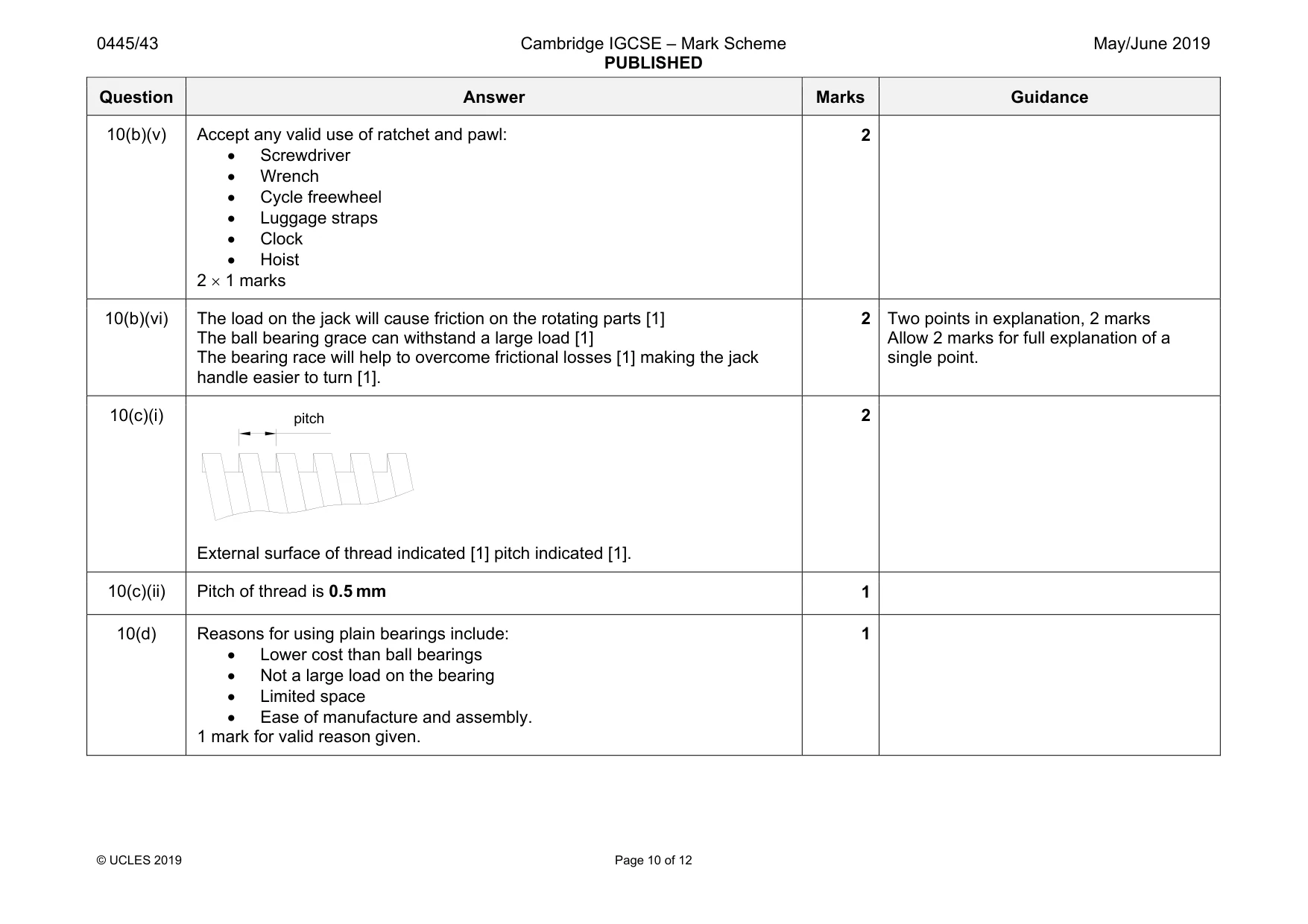
Mark scheme: 10(a)(i) Lever A is second order / class 2 1 10(a)(ii) Lever B is third order / class 3 1 10(a)(iii) Pushing forward on lever A will rotate / move the bucket [1], in a clockwise direction (oscillation) [1]. 2 Allow marks for understanding shown 10(a)(iv) Bearing used to provide rotation, 1 mark Type of bearing named / defined, 1 mark Functional method used, 1 mark Components / materials named, 1 mark. 4 Allow 1 mark for wheels used on legs for rotation. 10(b)(i) Conversion of motion is oscillating [1] to linear [1] 2 10(b)(ii) Operating the release valve will allow hydraulic fluid to return to the reservoir [1], causing the jack to lower [1]. The release valve will prevent any backflow / return of fluid to the master cylinder [1]. Valve can control descent speed of the jack [1]. 2 Any two points included in description, 2 marks. 10(b)(iii) MA = distance moved by effort / distance moved by load Distance moved by effort = 2 × π × 300, 1 mark =1884.96 1 mark 1884.96 / 5, = 376.99, 1 mark 3 Award marks for correct answer with no working. 10(b)(iv) The ratchet and pawl will allow less than a complete turn of the bar to be used [1] this is useful in restricted space [1]. 2 Both points needed for two marks. Allow prevention of accidental lowering of jack. Question Answer Marks Guidance 10(b)(v) Accept any valid use of ratchet and pawl: • Screwdriver • Wrench • Cycle freewheel • Luggage straps • Clock • Hoist 2 × 1 marks 2 10(b)(vi) The load on the jack will cause friction on the rotating parts [1] The ball bearing grace can withstand a large load [1] The bearing race will help to overcome frictional losses [1] making the jack handle easier to turn [1]. 2 Two points in explanation, 2 marks Allow 2 marks for full explanation of a single point. 10(c)(i) External surface of thread indicated [1] pitch indicated [1]. 2 10(c)(ii) Pitch of thread is 0.5 mm 1 10(d) Reasons for using plain bearings include: • Lower cost than ball bearings • Not a large load on the bearing • Limited space • Ease of manufacture and assembly. 1 mark for valid reason given. 1 pitch
Q11 · Four components and their symbols
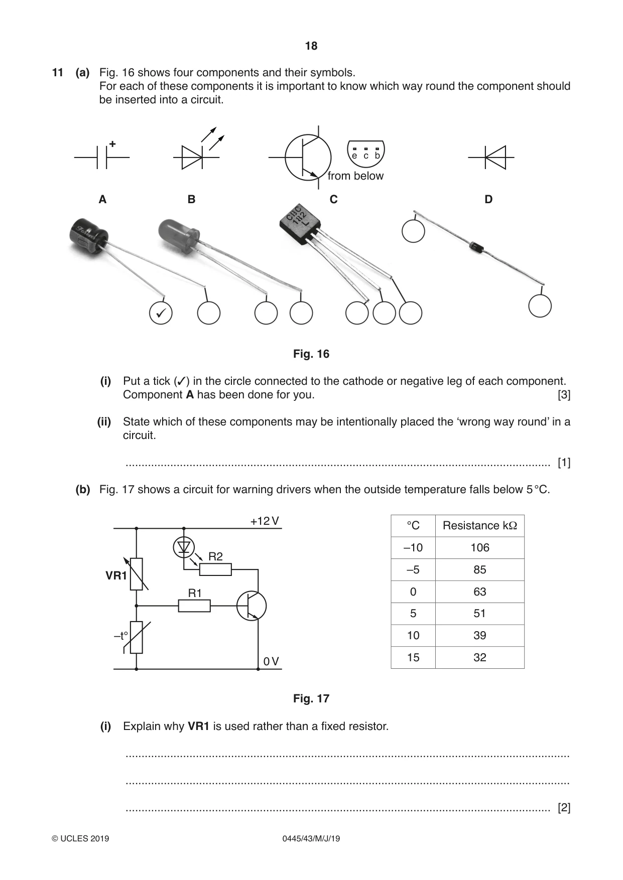
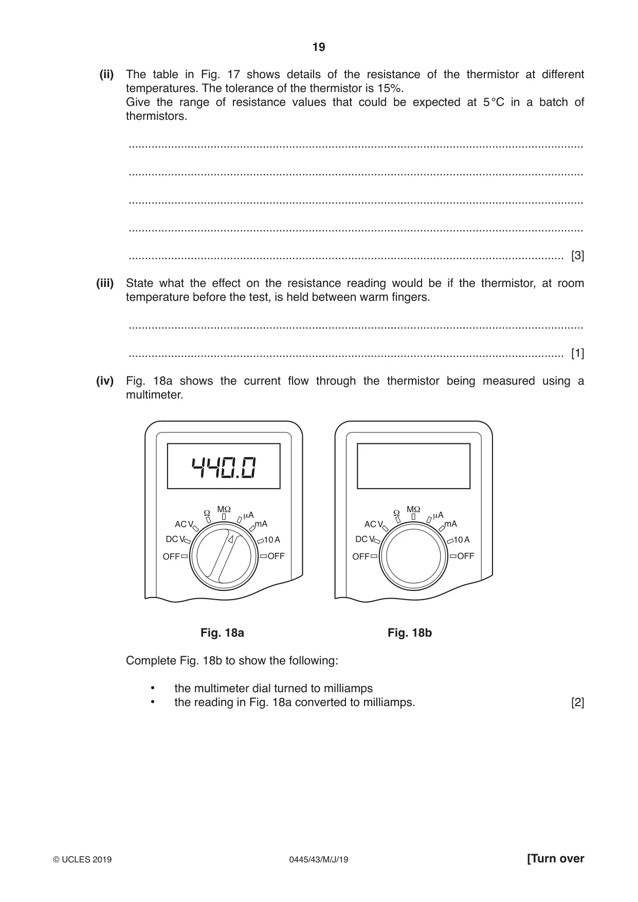
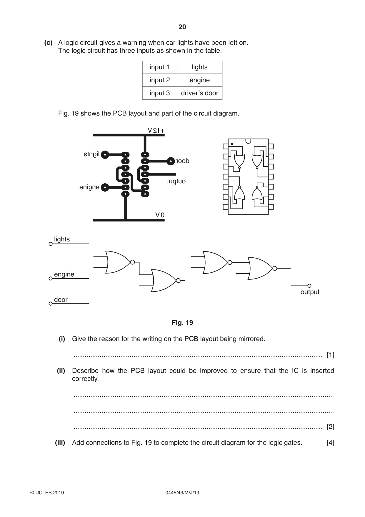
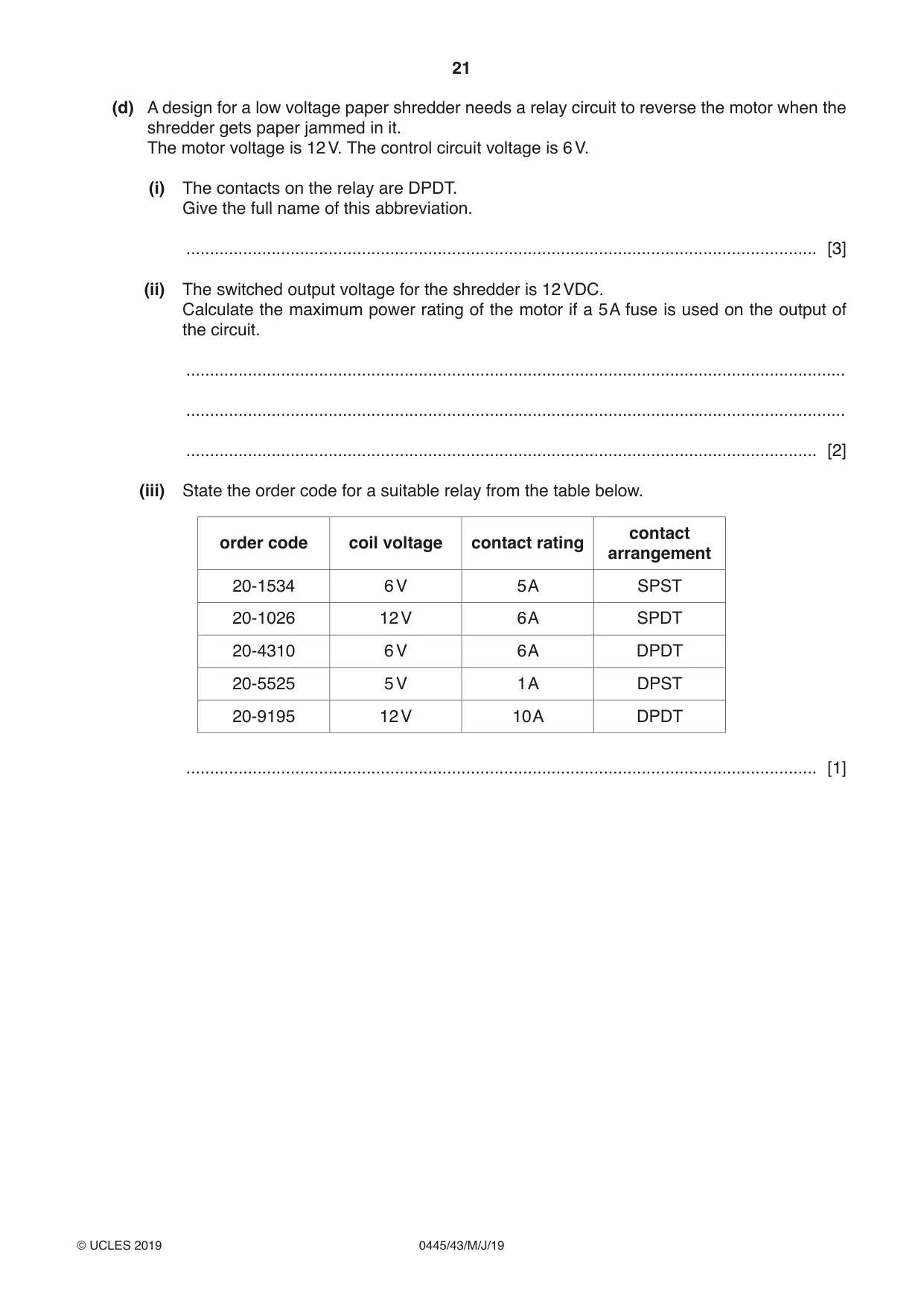
11 (a) Fig. 16 shows four components and their symbols. For each of these components it is important to know which way round the component should be inserted into a circuit. + e c b from below A B C D Fig. 16 (i) Put a tick (✓) in the circle connected to the cathode or negative leg of each component. Component A has been done for you. [3] (ii) State which of these components may be intentionally placed the ‘wrong way round’ in a circuit. ..................................................................................................................................... [1] (b) Fig. 17 shows a circuit for warning drivers when the outside temperature falls below 5 °C. +12 V °C Resistance kΩ –10 106 R2 –5 85 VR1 R1 0 63 5 51 –t° 10 39 15 32 0 V Fig. 17 (i) Explain why VR1 is used rather than a fixed resistor. ........................................................................................................................................... ........................................................................................................................................... ..................................................................................................................................... [2] (ii) The table in Fig. 17 shows details of the resistance of the thermistor at different temperatures. The tolerance of the thermistor is 15%. Give the range of resistance values that could be expected at 5 °C in a batch of thermistors. ........................................................................................................................................... ........................................................................................................................................... ........................................................................................................................................... ........................................................................................................................................... ..................................................................................................................................... [3] (iii) State what the effect on the resistance reading would be if the thermistor, at room temperature before the test, is held between warm fingers. ........................................................................................................................................... ..................................................................................................................................... [1] (iv) Fig. 18a shows the current flow through the thermistor being measured using a multimeter. Ω MΩ Ω MΩ μA μA AC V mA AC V mA DC V 10 A DC V 10 A OFF OFF OFF OFF Fig. 18a Fig. 18b Complete Fig. 18b to show the following: • the multimeter dial turned to milliamps • the reading in Fig. 18a converted to milliamps. [2] (c) A logic circuit gives a warning when car lights have been left on. The logic circuit has three inputs as shown in the table. input 1 lights input 2 engine input 3 driver’s door Fig. 19 shows the PCB layout and part of the circuit diagram. V +12 lights door output engine V 0 lights engine door Fig. 19 (i) Give the reason for the writing on the PCB layout being mirrored. ..................................................................................................................................... [1] (ii) Describe how the PCB layout could be improved to ensure that the IC is inserted correctly. ........................................................................................................................................... ........................................................................................................................................... ..................................................................................................................................... [2] (iii) Add connections to Fig. 19 to complete the circuit diagram for the logic gates. [4]
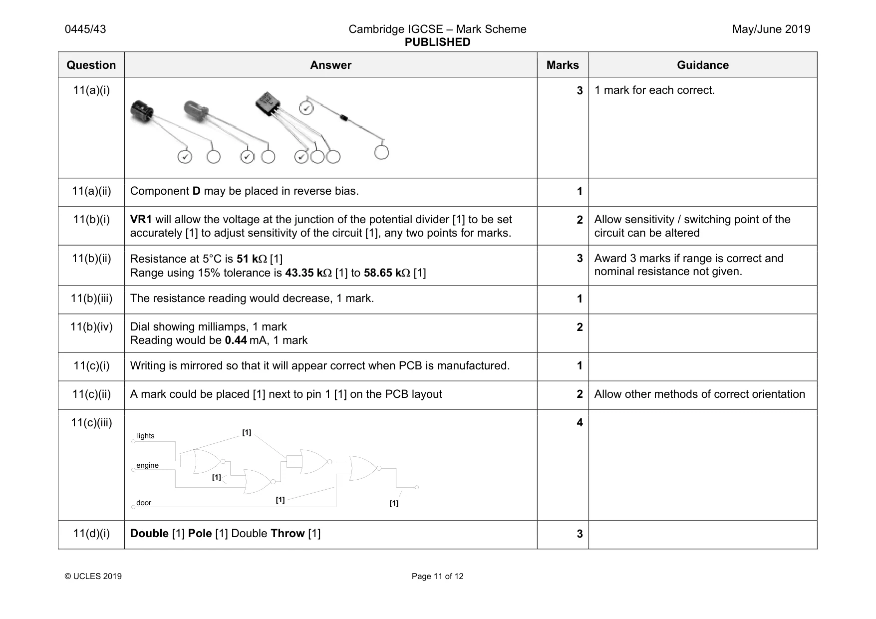
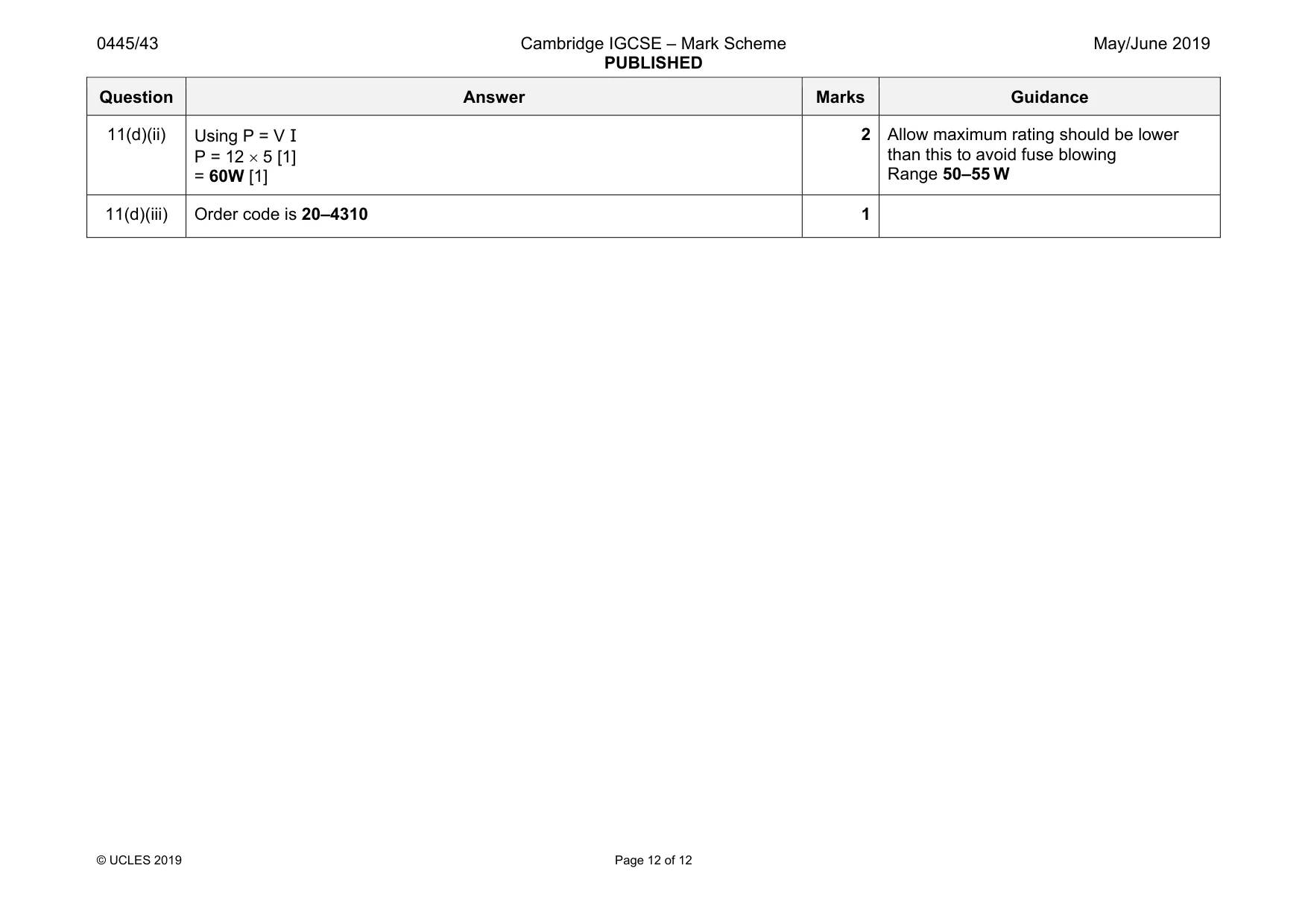
Mark scheme: 11(a)(i) 3 1 mark for each correct. 11(a)(ii) Component D may be placed in reverse bias. 1 11(b)(i) VR1 will allow the voltage at the junction of the potential divider [1] to be set accurately [1] to adjust sensitivity of the circuit [1], any two points for marks. 2 Allow sensitivity / switching point of the circuit can be altered 11(b)(ii) Resistance at 5°C is 51 kΩ [1] Range using 15% tolerance is 43.35 kΩ [1] to 58.65 kΩ [1] 3 Award 3 marks if range is correct and nominal resistance not given. 11(b)(iii) The resistance reading would decrease, 1 mark. 1 11(b)(iv) Dial showing milliamps, 1 mark Reading would be 0.44 mA, 1 mark 2 11(c)(i) Writing is mirrored so that it will appear correct when PCB is manufactured. 1 11(c)(ii) A mark could be placed [1] next to pin 1 [1] on the PCB layout 2 Allow other methods of correct orientation 11(c)(iii) 4 11(d)(i) Double [1] Pole [1] Double Throw [1] 3 lights engine door [1] [1] [1] [1] Question Answer Marks Guidance 11(d)(ii) Using P = V I P = 12 × 5 [1] = 60W [1] 2 Allow maximum rating should be lower than this to avoid fuse blowing Range 50–55 W 11(d)(iii) Order code is 20–4310 1
What was in this paper
The subtopics covered by these 11 questions, and how many questions each got. Open one in a new tab to see every Cambridge question on it.
What you needed in this session
Cambridge’s own grade thresholds for 2019 May/June, Paper 4 · Variant 3. A higher threshold means an easier paper — the bar moves with how the cohort did.