Cambridge IGCSE Design and Technology 0445 — 2019 May/June Paper 4 · Variant 2
0445/42/M/J/19 · 10 questions · 50 marks · ≈56 min
The question paper and its mark scheme, free to read here and free to download. This is Cambridge’s own paper, exactly as it was sat.
Question paper20 pages




Mark scheme12 pages
Answers below. Sit the paper first if you are practising.

Questions as text
Q1 · Name two machines used in manufacturing that can be controlled by a computer
1 (a) Name two machines used in manufacturing that can be controlled by a computer. 1 ................................................................................................................................................ 2 ................................................................................................................................................ [2] (b) Give two benefits of using CAM in batch production. 1 ................................................................................................................................................ ................................................................................................................................................... 2 ................................................................................................................................................ ................................................................................................................................................... [2]
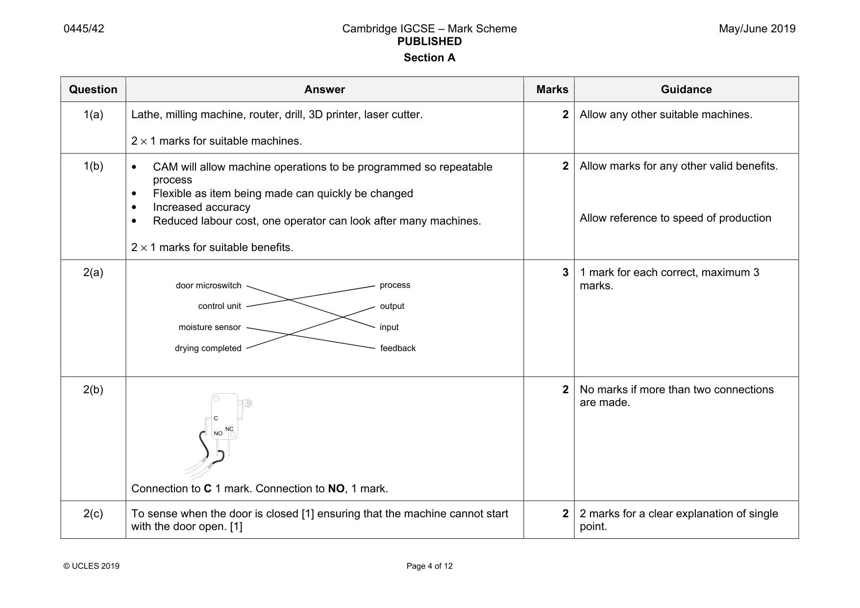
Mark scheme: 1(a) Lathe, milling machine, router, drill, 3D printer, laser cutter. 2 × 1 marks for suitable machines. 2 Allow any other suitable machines. 1(b) • CAM will allow machine operations to be programmed so repeatable process • Flexible as item being made can quickly be changed • Increased accuracy • Reduced labour cost, one operator can look after many machines. 2 × 1 marks for suitable benefits. 2 Allow marks for any other valid benefits. Allow reference to speed of production 1 mark for each correct, maximum 3
Q2 · A block diagram for the system used in a tumble drier
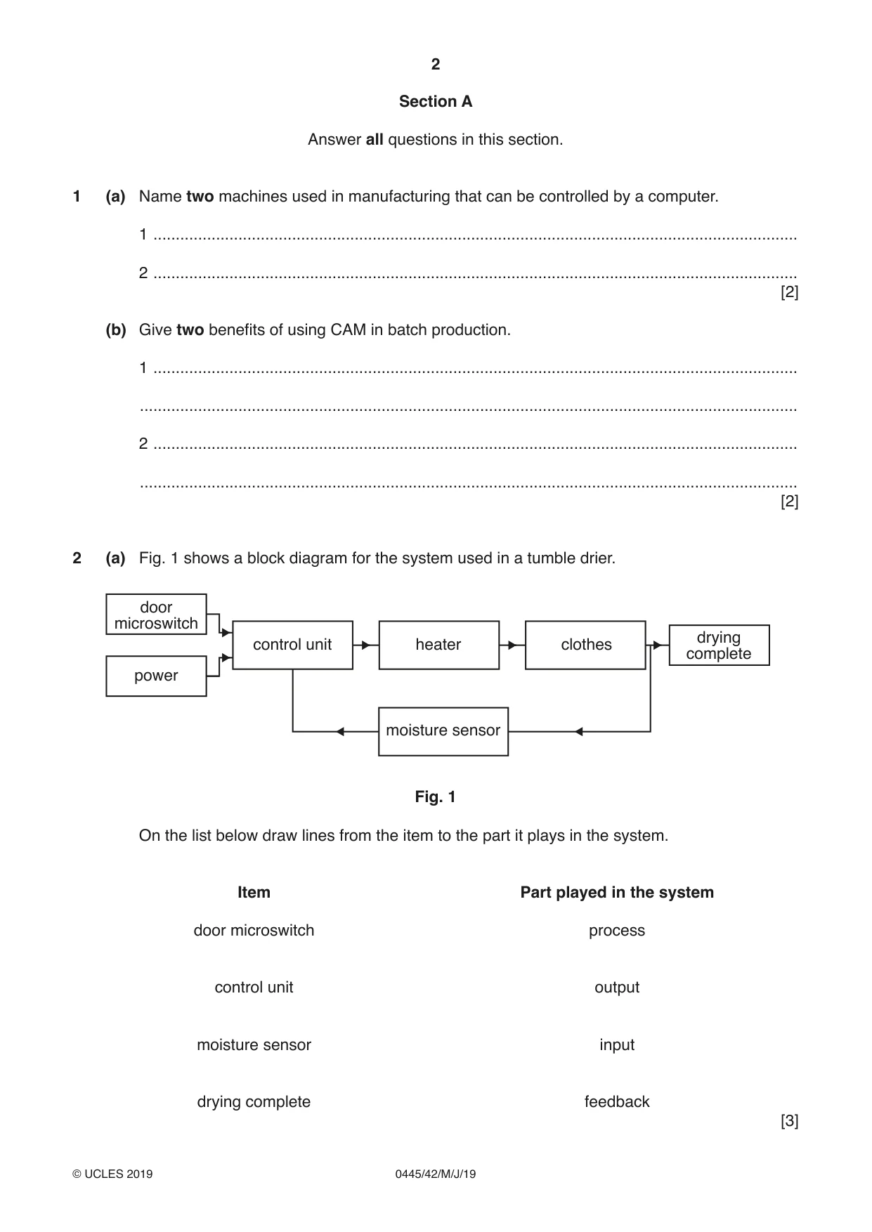
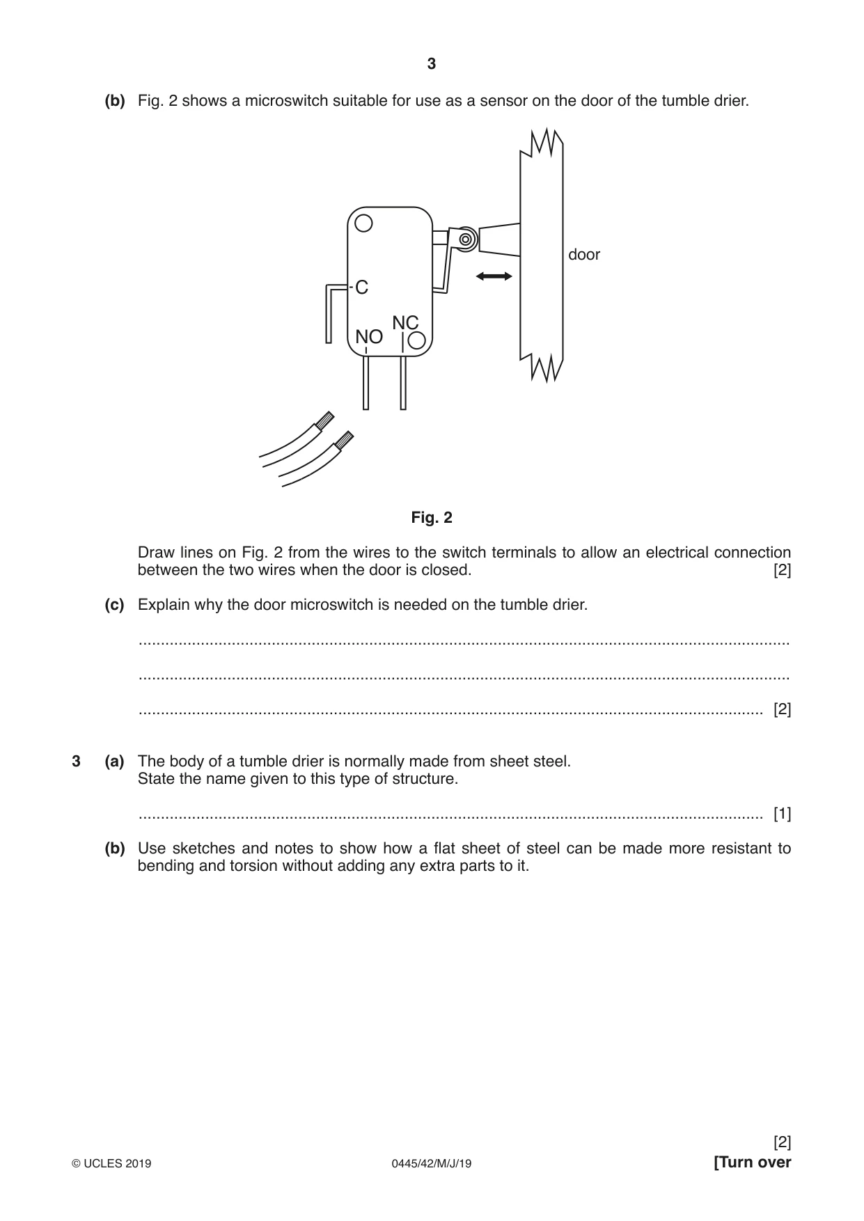
2 (a) Fig. 1 shows a block diagram for the system used in a tumble drier. door microswitch drying control unit heater clothes complete power moisture sensor Fig. 1 On the list below draw lines from the item to the part it plays in the system. Item Part played in the system door microswitch process control unit output moisture sensor input drying complete feedback [3] (b) Fig. 2 shows a microswitch suitable for use as a sensor on the door of the tumble drier. door C NC NO Fig. 2 Draw lines on Fig. 2 from the wires to the switch terminals to allow an electrical connection between the two wires when the door is closed. [2] (c) Explain why the door microswitch is needed on the tumble drier. ................................................................................................................................................... ................................................................................................................................................... ............................................................................................................................................. [2]
Mark scheme: 2(a) 3 marks. 2(b) Connection to C 1 mark. Connection to NO, 1 mark. 2 No marks if more than two connections are made. 2(c) To sense when the door is closed [1] ensuring that the machine cannot start with the door open. [1] 2 2 marks for a clear explanation of single point. door microswitch control unit moisture sensor drying completed process output input feedback C NO NC
Q3 · The body of a tumble drier is normally made from sheet steel
3 (a) The body of a tumble drier is normally made from sheet steel. State the name given to this type of structure. ............................................................................................................................................. [1] (b) Use sketches and notes to show how a flat sheet of steel can be made more resistant to bending and torsion without adding any extra parts to it.
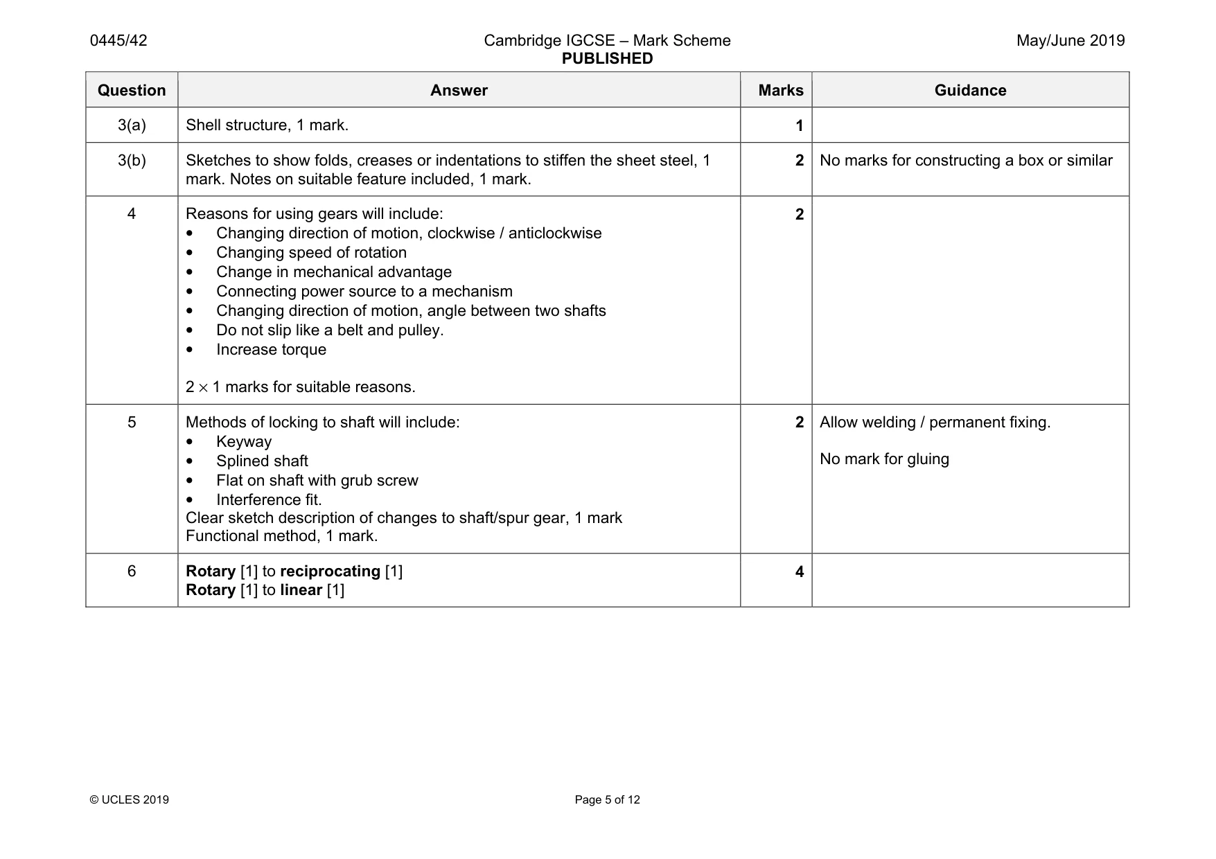
Mark scheme: 3(a) Shell structure, 1 mark. 1 3(b) Sketches to show folds, creases or indentations to stiffen the sheet steel, 1 mark. Notes on suitable feature included, 1 mark. 2 No marks for constructing a box or similar
Q4 · Give two reasons for using gears in a mechanism
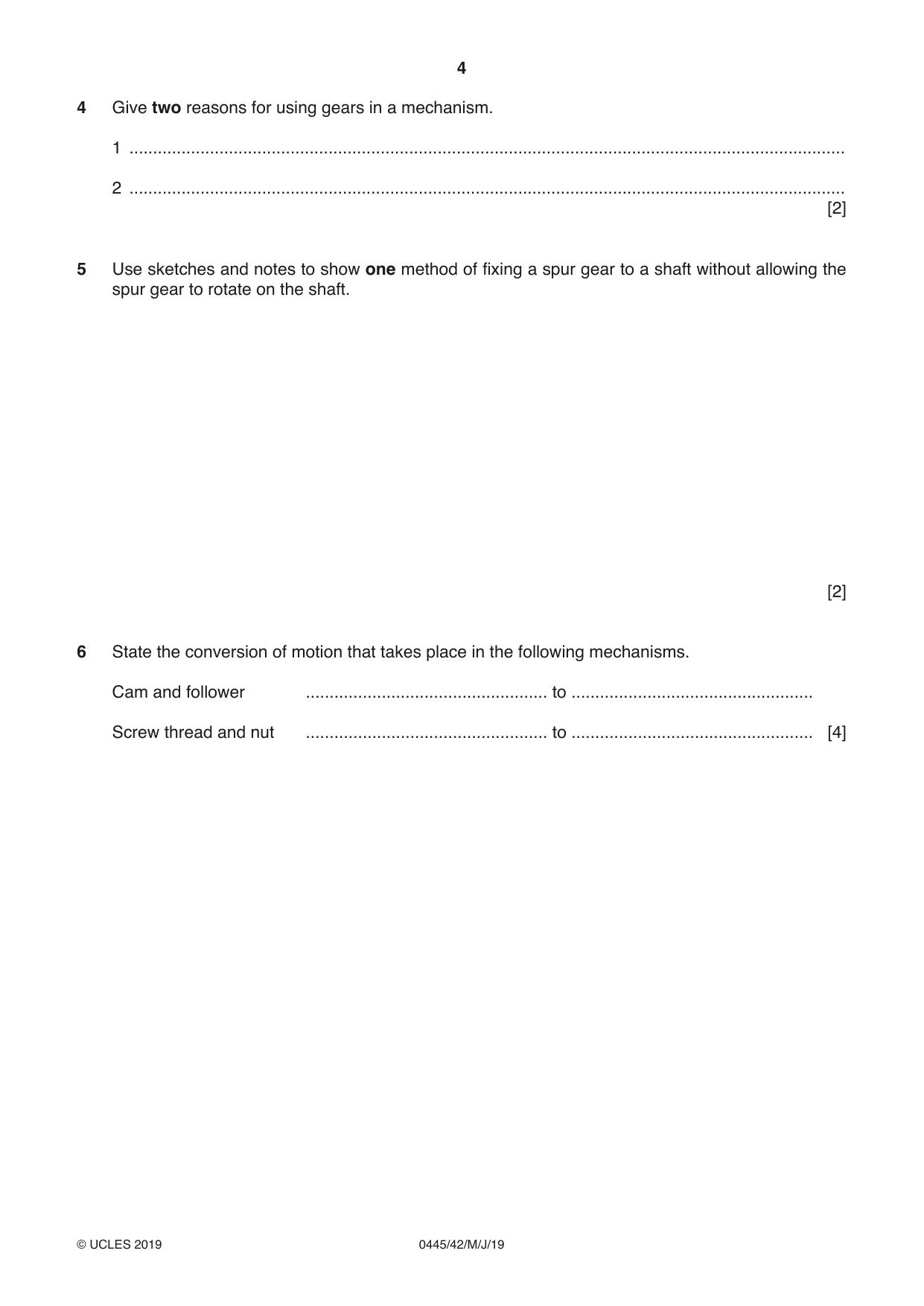
4 Give two reasons for using gears in a mechanism. 1 ....................................................................................................................................................... 2 ....................................................................................................................................................... [2]
Mark scheme: 4 Reasons for using gears will include: • Changing direction of motion, clockwise / anticlockwise • Changing speed of rotation • Change in mechanical advantage • Connecting power source to a mechanism • Changing direction of motion, angle between two shafts • Do not slip like a belt and pulley. • Increase torque 2 × 1 marks for suitable reasons. 2 Allow welding / permanent fixing.
Q5 · Use sketches and notes to show one method of fixing a spur gear to a shaft without…
5 Use sketches and notes to show one method of fixing a spur gear to a shaft without allowing the spur gear to rotate on the shaft. [2]
Mark scheme: 5 Methods of locking to shaft will include: • Keyway • Splined shaft • Flat on shaft with grub screw • Interference fit. Clear sketch description of changes to shaft/spur gear, 1 mark Functional method, 1 mark. 2 No mark for gluing
Q6 · State the conversion of motion that takes place in the following mechanisms
6 State the conversion of motion that takes place in the following mechanisms. Cam and follower ................................................... to ................................................... Screw thread and nut ................................................... to ................................................... [4]
Mark scheme: 6 Rotary [1] to reciprocating [1] Rotary [1] to linear [1] 4
Q7 · Two methods of fixing wires to a circuit board
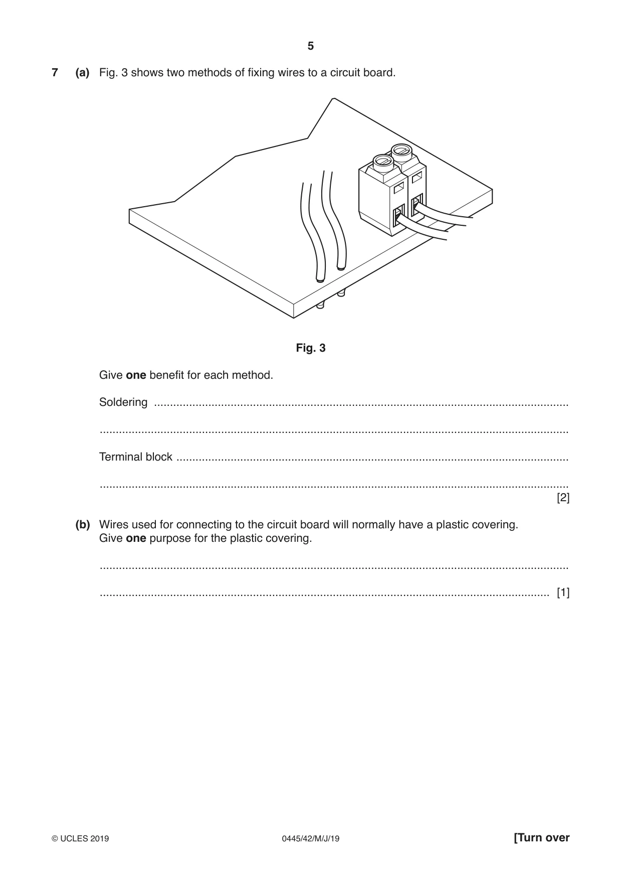
7 (a) Fig. 3 shows two methods of fixing wires to a circuit board. Fig. 3 Give one benefit for each method. Soldering .................................................................................................................................. ................................................................................................................................................... Terminal block ........................................................................................................................... ................................................................................................................................................... [2] (b) Wires used for connecting to the circuit board will normally have a plastic covering. Give one purpose for the plastic covering. ................................................................................................................................................... ............................................................................................................................................. [1]
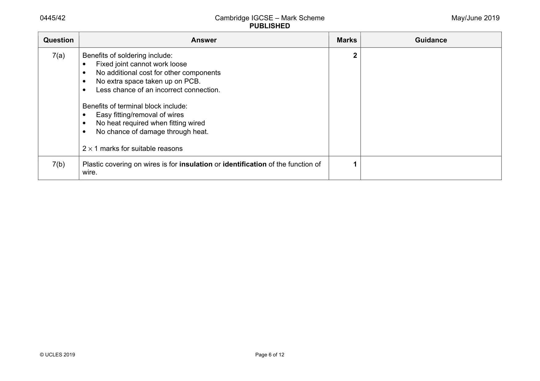
Mark scheme: 7(a) Benefits of soldering include: • Fixed joint cannot work loose • No additional cost for other components • No extra space taken up on PCB. • Less chance of an incorrect connection. Benefits of terminal block include: • Easy fitting/removal of wires • No heat required when fitting wired • No chance of damage through heat. 2 × 1 marks for suitable reasons 2 7(b) Plastic covering on wires is for insulation or identification of the function of wire. 1
Q8 · A table of materials that can be used for a load bearing beam and a list of properties…
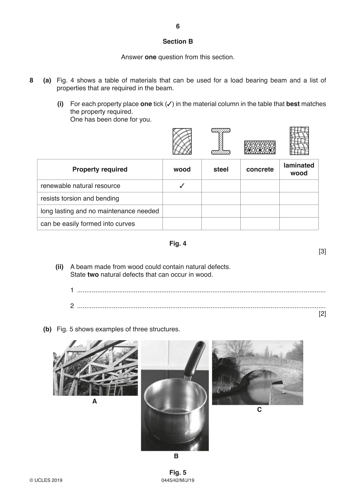
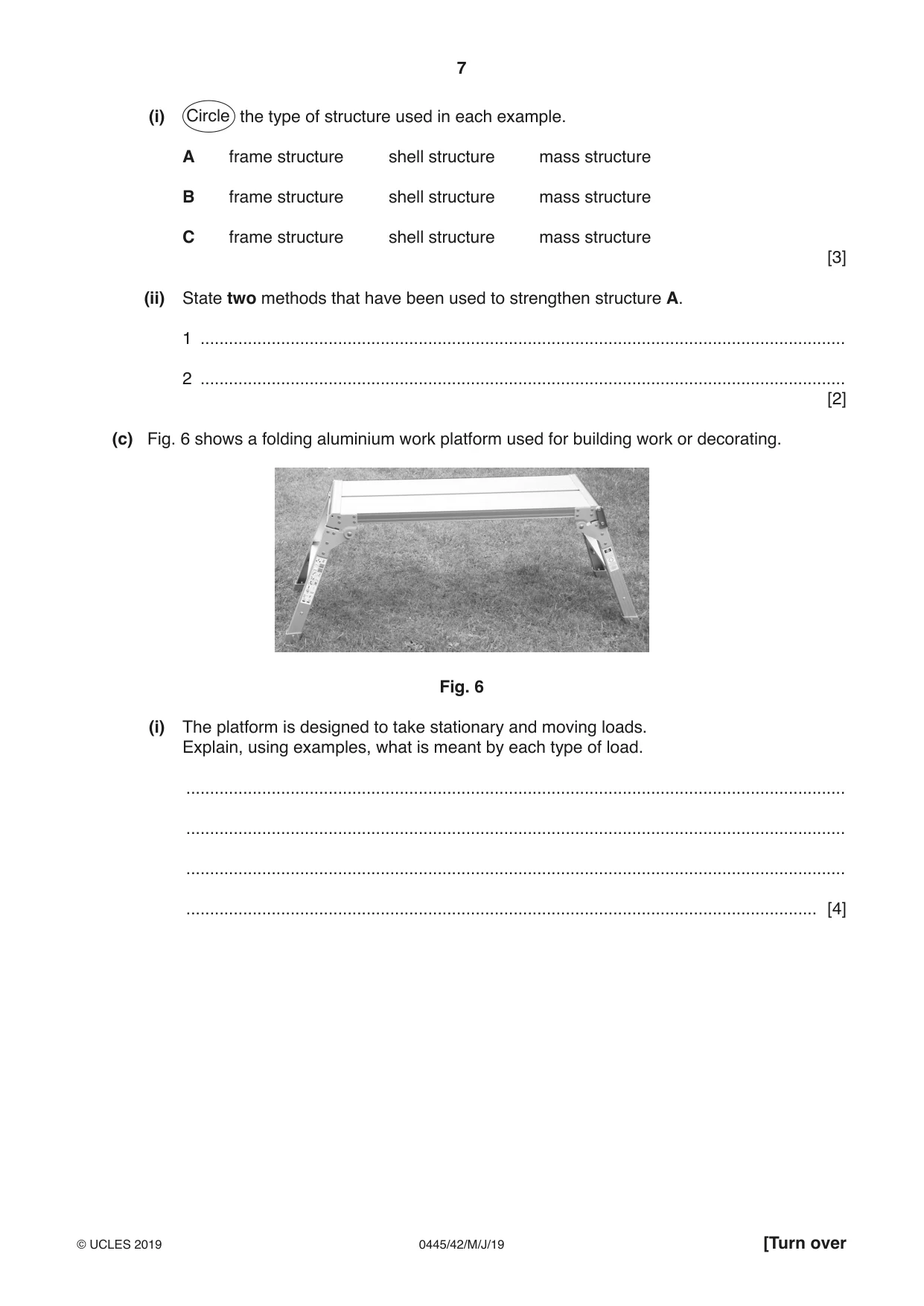
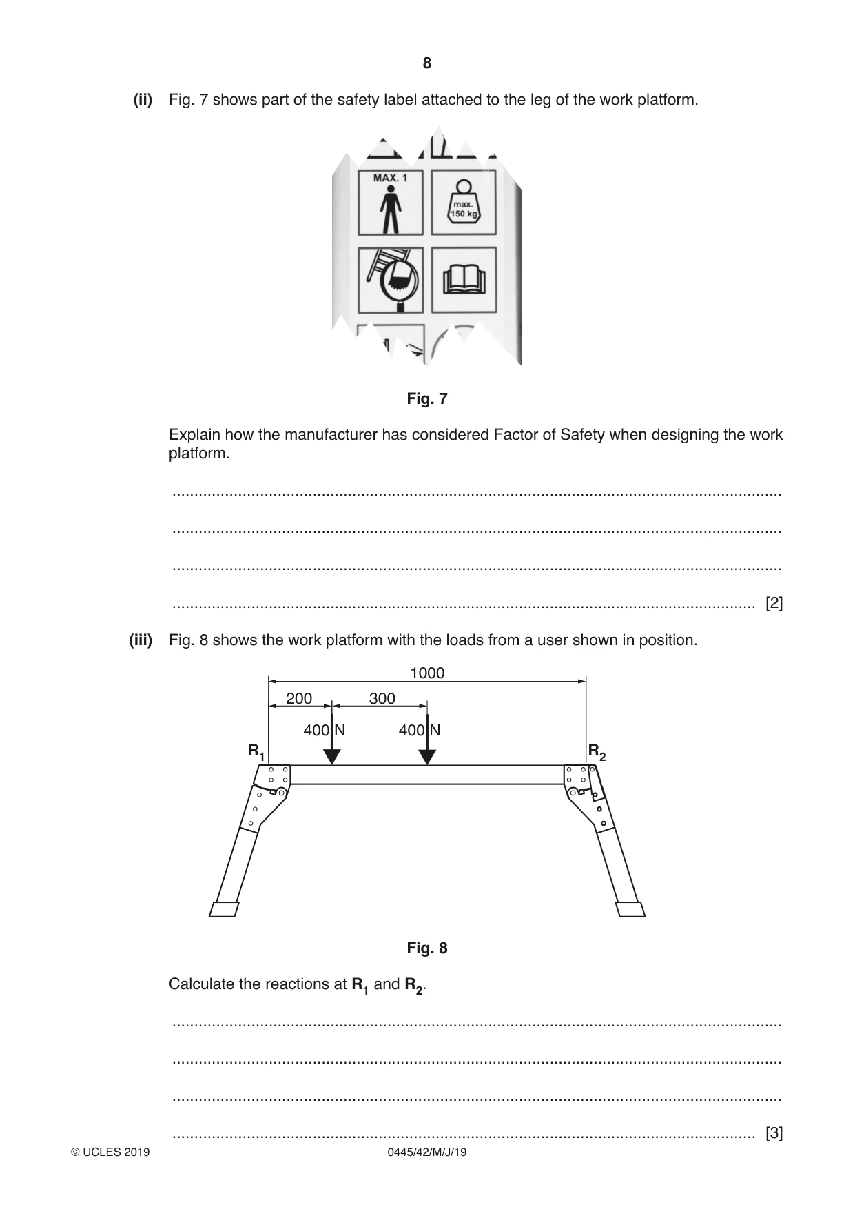
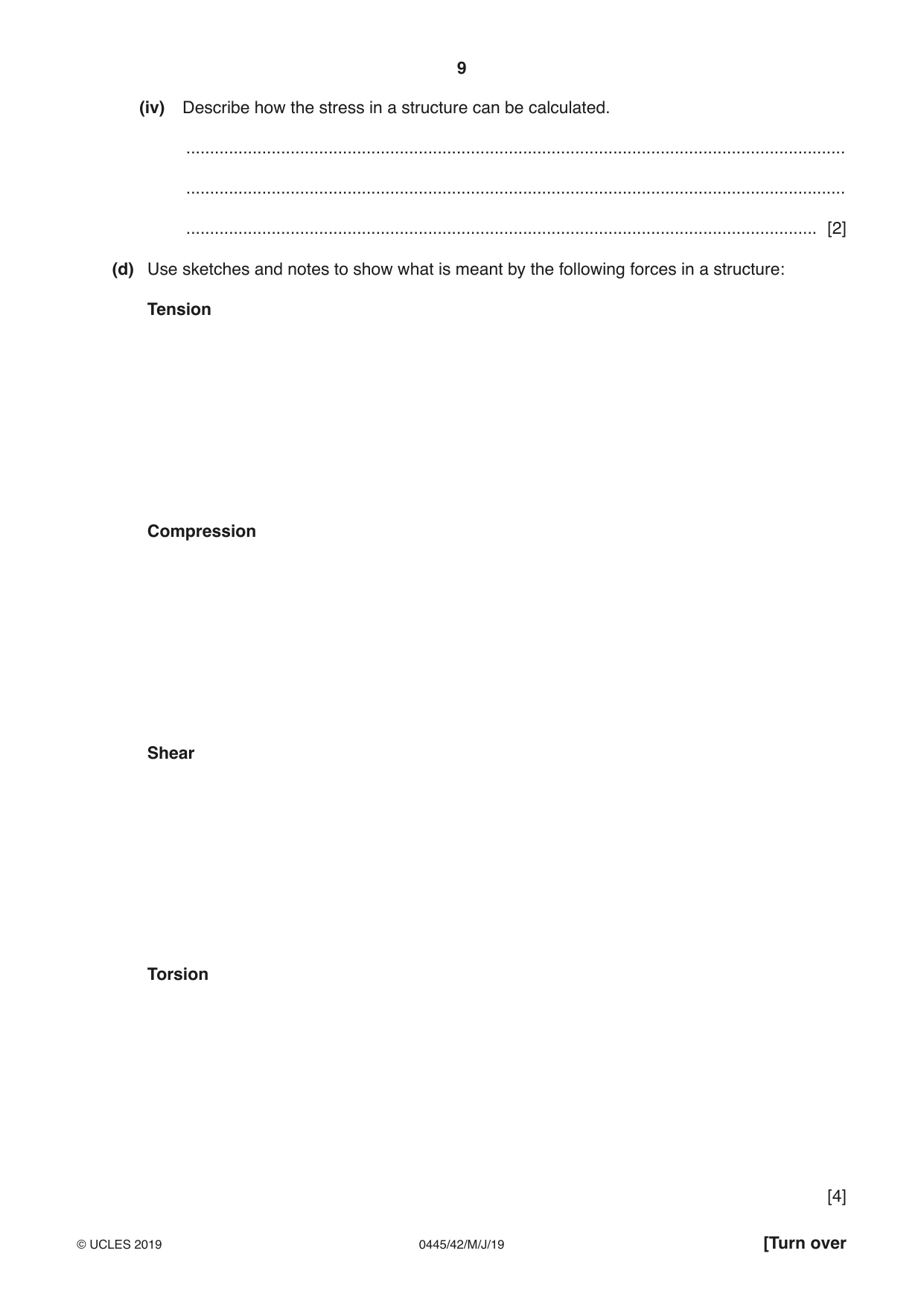
8 (a) Fig. 4 shows a table of materials that can be used for a load bearing beam and a list of properties that are required in the beam. (i) For each property place one tick (✓) in the material column in the table that best matches the property required. One has been done for you. laminated Property required wood steel concrete wood ✓ renewable natural resource resists torsion and bending long lasting and no maintenance needed can be easily formed into curves Fig. 4 [3] (ii) A beam made from wood could contain natural defects. State two natural defects that can occur in wood. 1 ........................................................................................................................................ 2 ........................................................................................................................................ [2] (b) Fig. 5 shows examples of three structures. A C B Fig. 5 (i) Circle the type of structure used in each example. A frame structure shell structure mass structure B frame structure shell structure mass structure C frame structure shell structure mass structure [3] (ii) State two methods that have been used to strengthen structure A. 1 ........................................................................................................................................ 2 ........................................................................................................................................ [2] (c) Fig. 6 shows a folding aluminium work platform used for building work or decorating. Fig. 6 (i) The platform is designed to take stationary and moving loads. Explain, using examples, what is meant by each type of load. ........................................................................................................................................... ........................................................................................................................................... ........................................................................................................................................... ..................................................................................................................................... [4] (ii) Fig. 7 shows part of the safety label attached to the leg of the work platform. Fig. 7 Explain how the manufacturer has considered Factor of Safety when designing the work platform. ........................................................................................................................................... ........................................................................................................................................... ........................................................................................................................................... ..................................................................................................................................... [2] (iii) Fig. 8 shows the work platform with the loads from a user shown in position. 1000 200 300 400 N 400 N R1 R2 Fig. 8 Calculate the reactions at R1 and R2. ........................................................................................................................................... ........................................................................................................................................... ........................................................................................................................................... ..................................................................................................................................... [3] (iv) Describe how the stress in a structure can be calculated. ........................................................................................................................................... ........................................................................................................................................... ..................................................................................................................................... [2] (d) Use sketches and notes to show what is meant by the following forces in a structure: Tension Compression Shear Torsion [4]
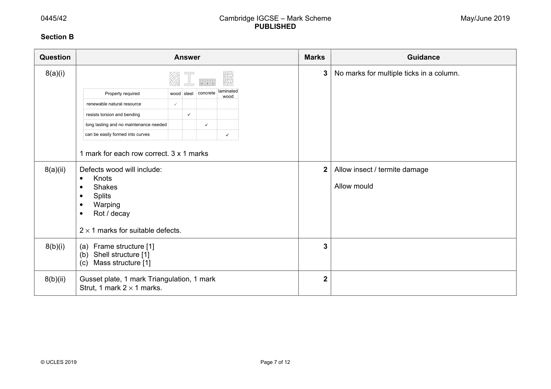
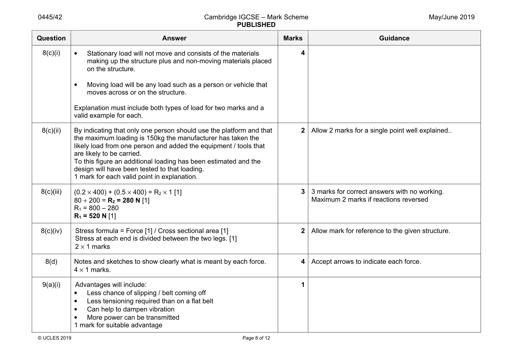
Mark scheme: 8(a)(i) 1 mark for each row correct. 3 x 1 marks 3 8(a)(ii) Defects wood will include: • Knots • Shakes • Splits • Warping • Rot / decay 2 × 1 marks for suitable defects. 2 Allow insect / termite damage Allow mould 8(b)(i) (a) Frame structure [1] (b) Shell structure [1] (c) Mass structure [1] 3 8(b)(ii) Gusset plate, 1 mark Triangulation, 1 mark Strut, 1 mark 2 × 1 marks. 2 renewable natural resource resists torsion and bending long lasting and no maintenance needed can be easily formed into curves Property required steel concrete wood laminated wood 9 9 9 9 Question Answer Marks Guidance 8(c)(i) • Stationary load will not move and consists of the materials making up the structure plus and non-moving materials placed on the structure. • Moving load will be any load such as a person or vehicle that moves across or on the structure. Explanation must include both types of load for two marks and a valid example for each. 4 8(c)(ii) By indicating that only one person should use the platform and that the maximum loading is 150kg the manufacturer has taken the likely load from one person and added the equipment / tools that are likely to be carried. To this figure an additional loading has been estimated and the design will have been tested to that loading. 1 mark for each valid point in explanation. 2 Allow 2 marks for a single point well explained.. 8(c)(iii) (0.2 × 400) + (0.5 × 400) = R2 × 1 [1] 80 + 200 = R2 = 280 N [1] R1 = 800 – 280 R1 = 520 N [1] 3 3 marks for correct answers with no working. Maximum 2 marks if reactions reversed 8(c)(iv) Stress formula = Force [1] / Cross sectional area [1] Stress at each end is divided between the two legs. [1] 2 × 1 marks 2 Allow mark for reference to the given structure. 8(d) Notes and sketches to show clearly what is meant by each force. 4 × 1 marks. 4 Accept arrows to indicate each force.
Q9 · A vee belt and pulley system
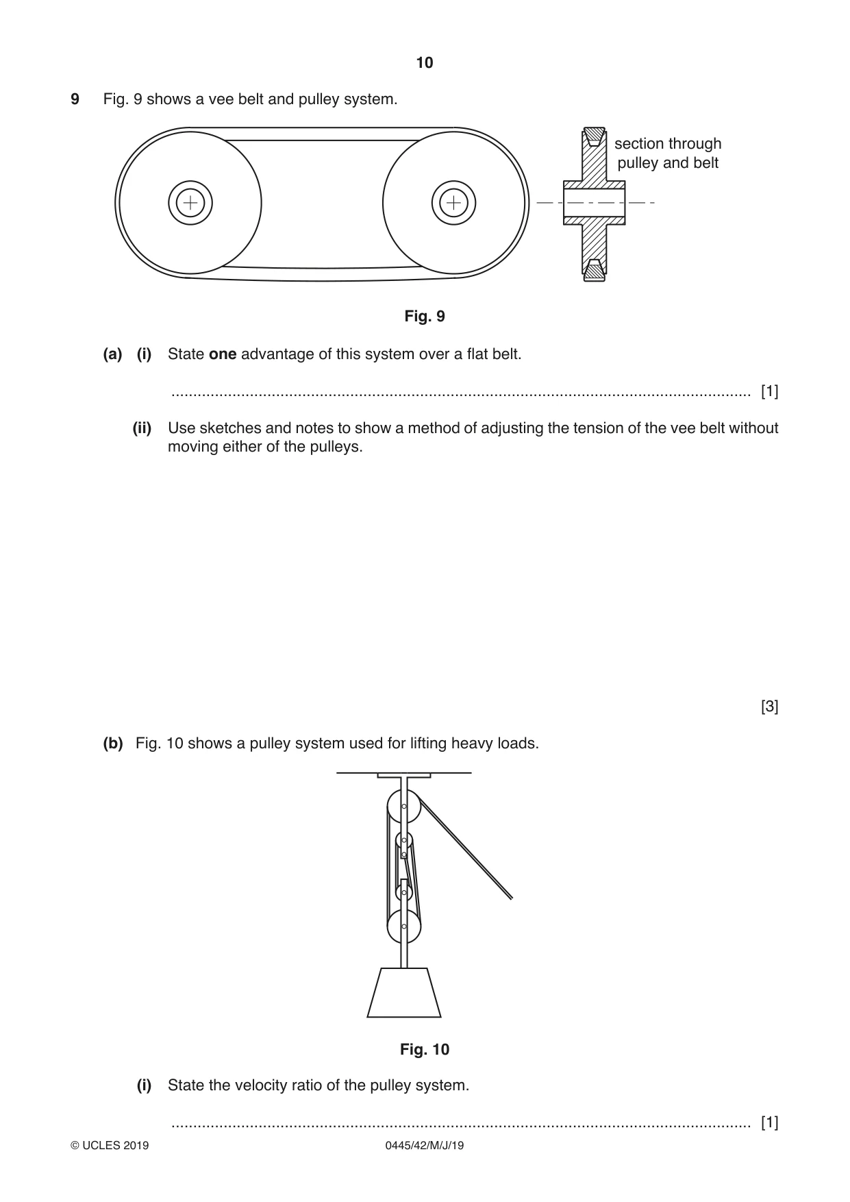
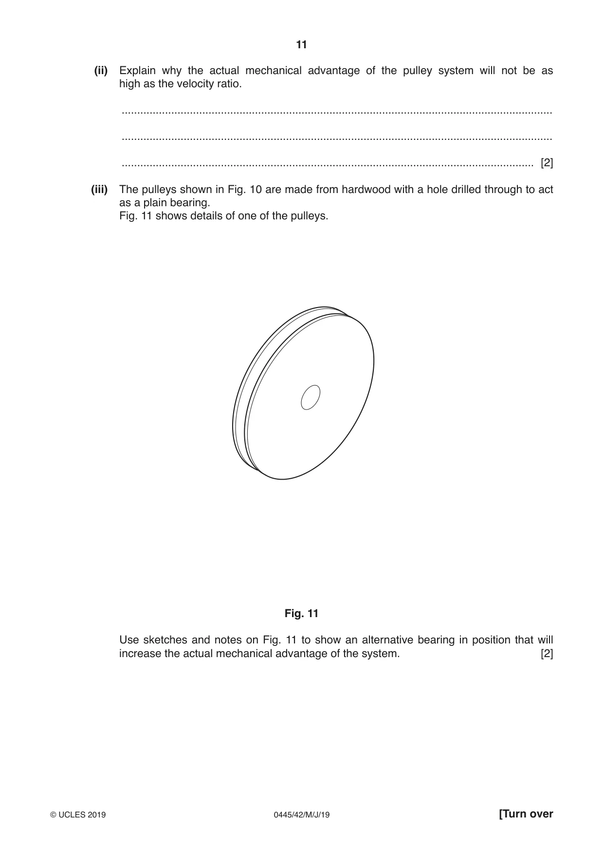
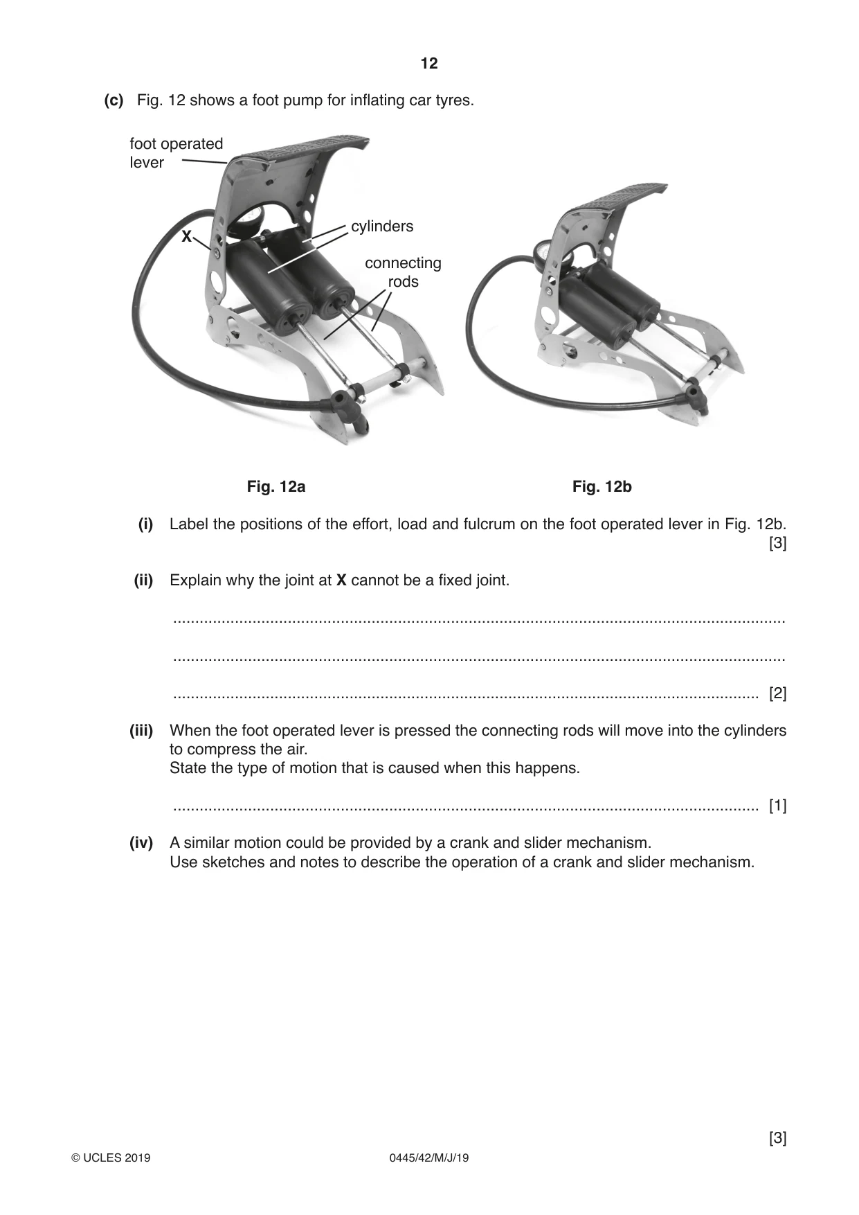
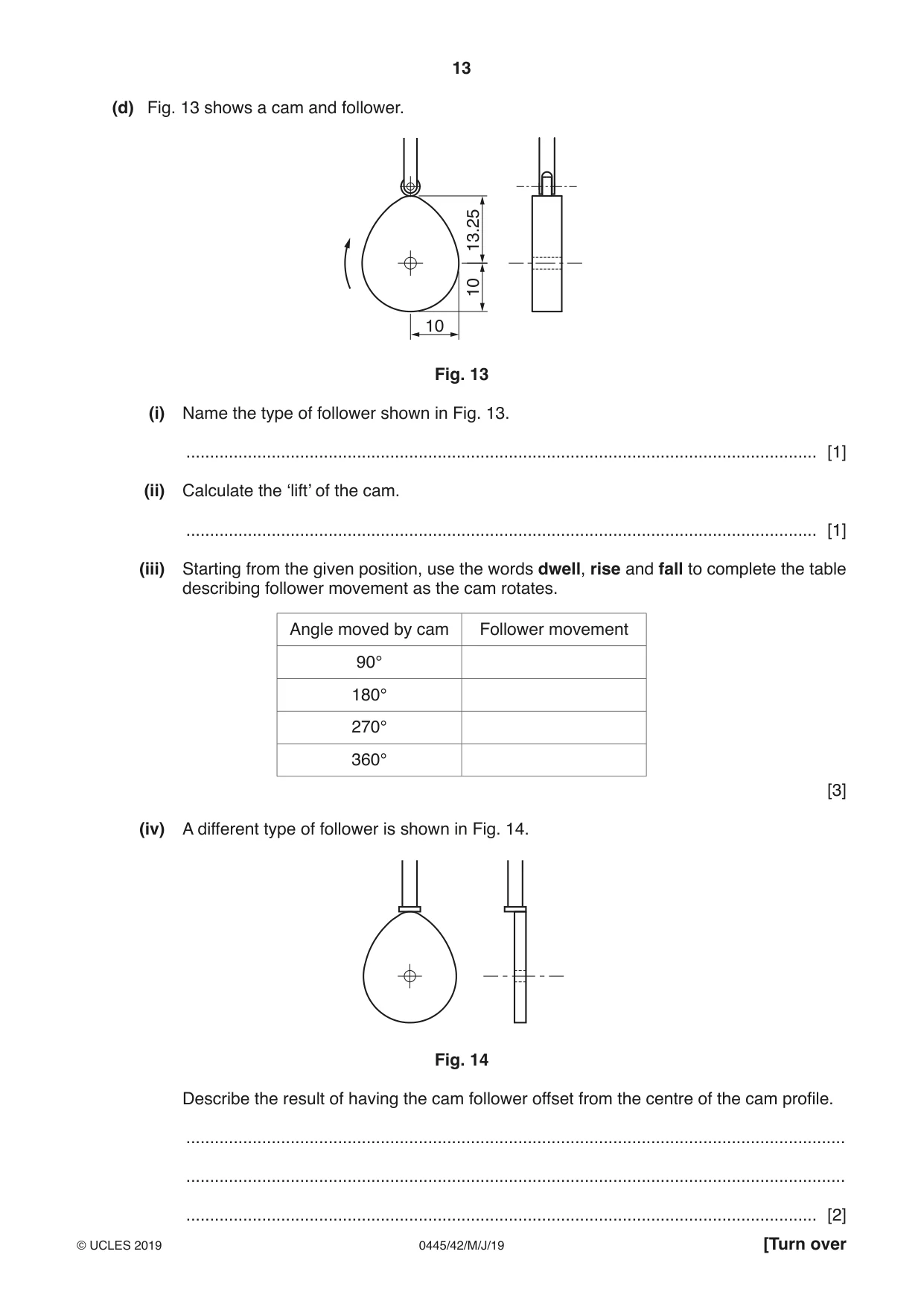
9 Fig. 9 shows a vee belt and pulley system. section through pulley and belt Fig. 9 (a) (i) State one advantage of this system over a flat belt. ..................................................................................................................................... [1] (ii) Use sketches and notes to show a method of adjusting the tension of the vee belt without moving either of the pulleys. [3] (b) Fig. 10 shows a pulley system used for lifting heavy loads. Fig. 10 (i) State the velocity ratio of the pulley system. ..................................................................................................................................... [1] (ii) Explain why the actual mechanical advantage of the pulley system will not be as high as the velocity ratio. ........................................................................................................................................... ........................................................................................................................................... ..................................................................................................................................... [2] (iii) The pulleys shown in Fig. 10 are made from hardwood with a hole drilled through to act as a plain bearing. Fig. 11 shows details of one of the pulleys. Fig. 11 Use sketches and notes on Fig. 11 to show an alternative bearing in position that will increase the actual mechanical advantage of the system. [2] (c) Fig. 12 shows a foot pump for inflating car tyres. foot operated lever cylinders X connecting rods Fig. 12a Fig. 12b (i) Label the positions of the effort, load and fulcrum on the foot operated lever in Fig. 12b. [3] (ii) Explain why the joint at X cannot be a fixed joint. ........................................................................................................................................... ........................................................................................................................................... ..................................................................................................................................... [2] (iii) When the foot operated lever is pressed the connecting rods will move into the cylinders to compress the air. State the type of motion that is caused when this happens. ..................................................................................................................................... [1] (iv) A similar motion could be provided by a crank and slider mechanism. Use sketches and notes to describe the operation of a crank and slider mechanism. [3] (d) Fig. 13 shows a cam and follower. 13.25 10 10 Fig. 13 (i) Name the type of follower shown in Fig. 13. ..................................................................................................................................... [1] (ii) Calculate the ‘lift’ of the cam. ..................................................................................................................................... [1] (iii) Starting from the given position, use the words dwell, rise and fall to complete the table describing follower movement as the cam rotates. Angle moved by cam Follower movement 90° 180° 270° 360° [3] (iv) A different type of follower is shown in Fig. 14. Fig. 14 Describe the result of having the cam follower offset from the centre of the cam profile. ........................................................................................................................................... ........................................................................................................................................... ..................................................................................................................................... [2]
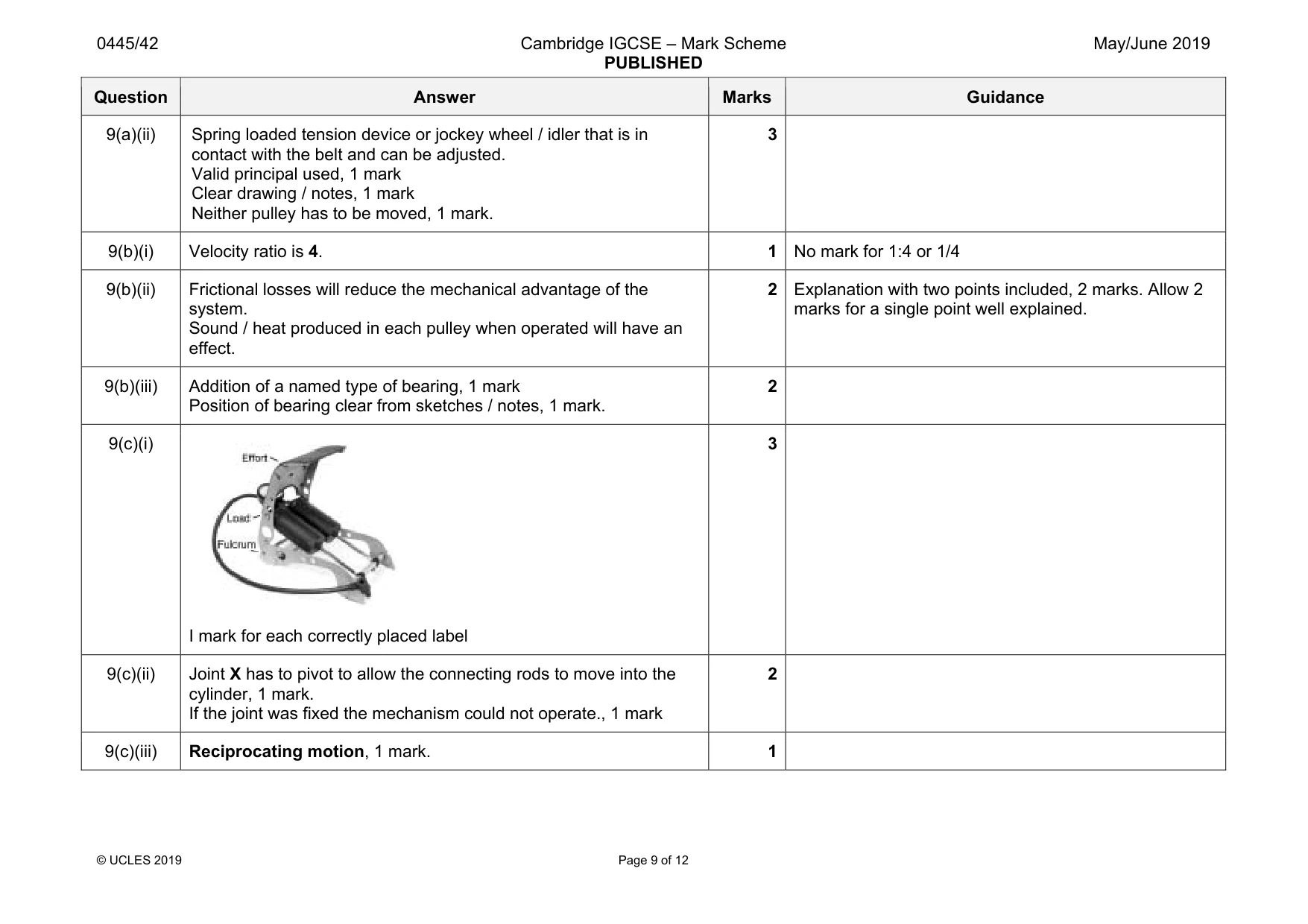
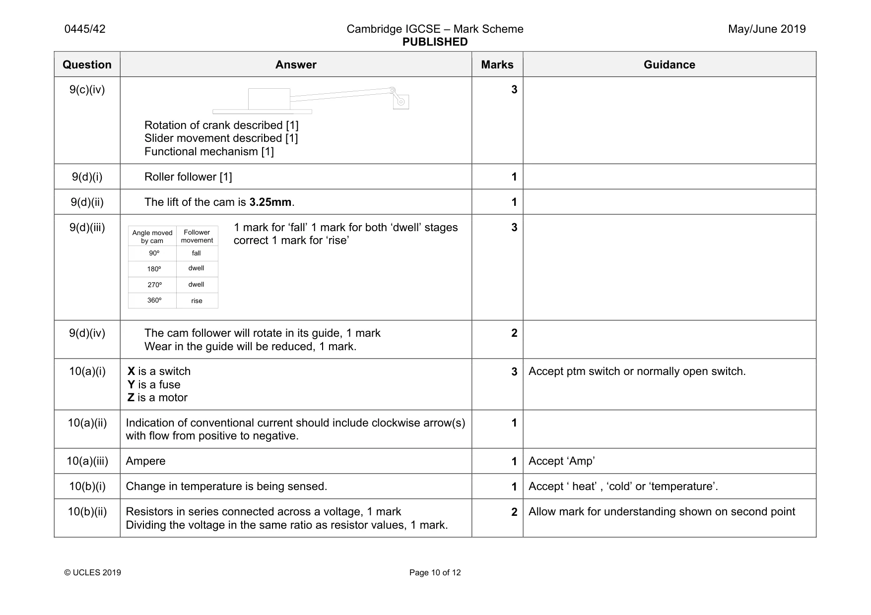
Mark scheme: 9(a)(i) Advantages will include: • Less chance of slipping / belt coming off • Less tensioning required than on a flat belt • Can help to dampen vibration • More power can be transmitted 1 mark for suitable advantage 1 Question Answer Marks Guidance 9(a)(ii) Spring loaded tension device or jockey wheel / idler that is in contact with the belt and can be adjusted. Valid principal used, 1 mark Clear drawing / notes, 1 mark Neither pulley has to be moved, 1 mark. 3 9(b)(i) Velocity ratio is 4. 1 No mark for 1:4 or 1/4 9(b)(ii) Frictional losses will reduce the mechanical advantage of the system. Sound / heat produced in each pulley when operated will have an effect. 2 Explanation with two points included, 2 marks. Allow 2 marks for a single point well explained. 9(b)(iii) Addition of a named type of bearing, 1 mark Position of bearing clear from sketches / notes, 1 mark. 2 9(c)(i) I mark for each correctly placed label 3 9(c)(ii) Joint X has to pivot to allow the connecting rods to move into the cylinder, 1 mark. If the joint was fixed the mechanism could not operate., 1 mark 2 9(c)(iii) Reciprocating motion, 1 mark. 1 Question Answer Marks Guidance 9(c)(iv) Rotation of crank described [1] Slider movement described [1] Functional mechanism [1] 3 9(d)(i) Roller follower [1] 1 9(d)(ii) The lift of the cam is 3.25mm. 1 9(d)(iii) 1 mark for ‘fall’ 1 mark for both ‘dwell’ stages correct 1 mark for ‘rise’ 3 9(d)(iv) The cam follower will rotate in its guide, 1 mark Wear in the guide will be reduced, 1 mark. 2 Angle moved by cam Follower movement 90º 180º 270º 360º fall dwell rise dwell
Q10 · A simple electronic circuit is shown in Fig
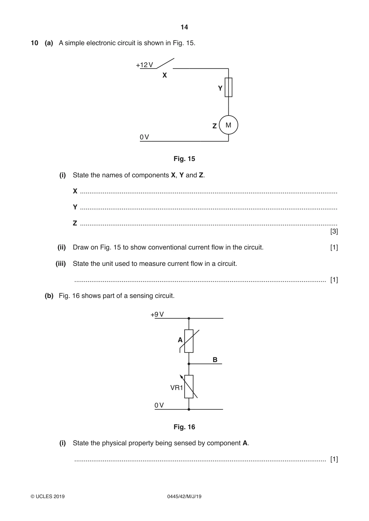
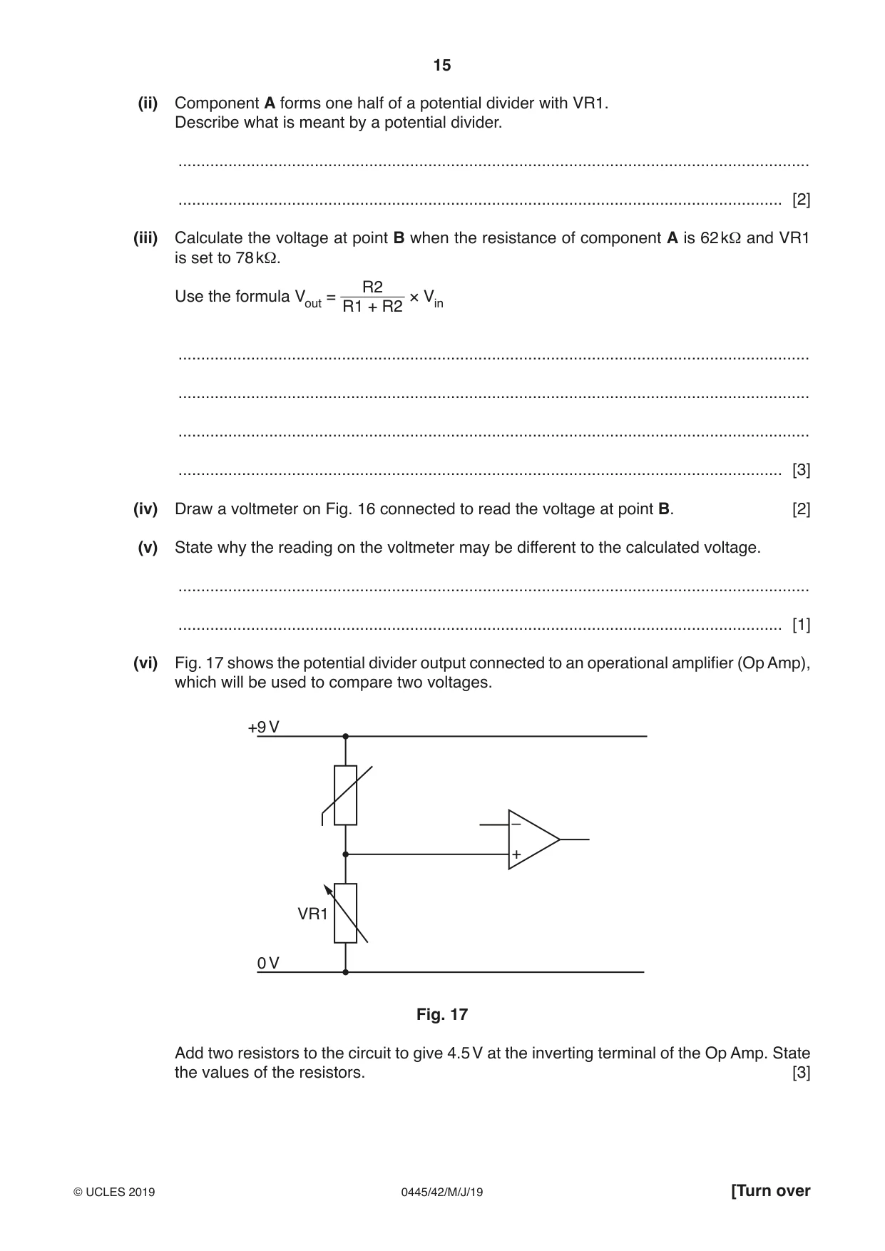
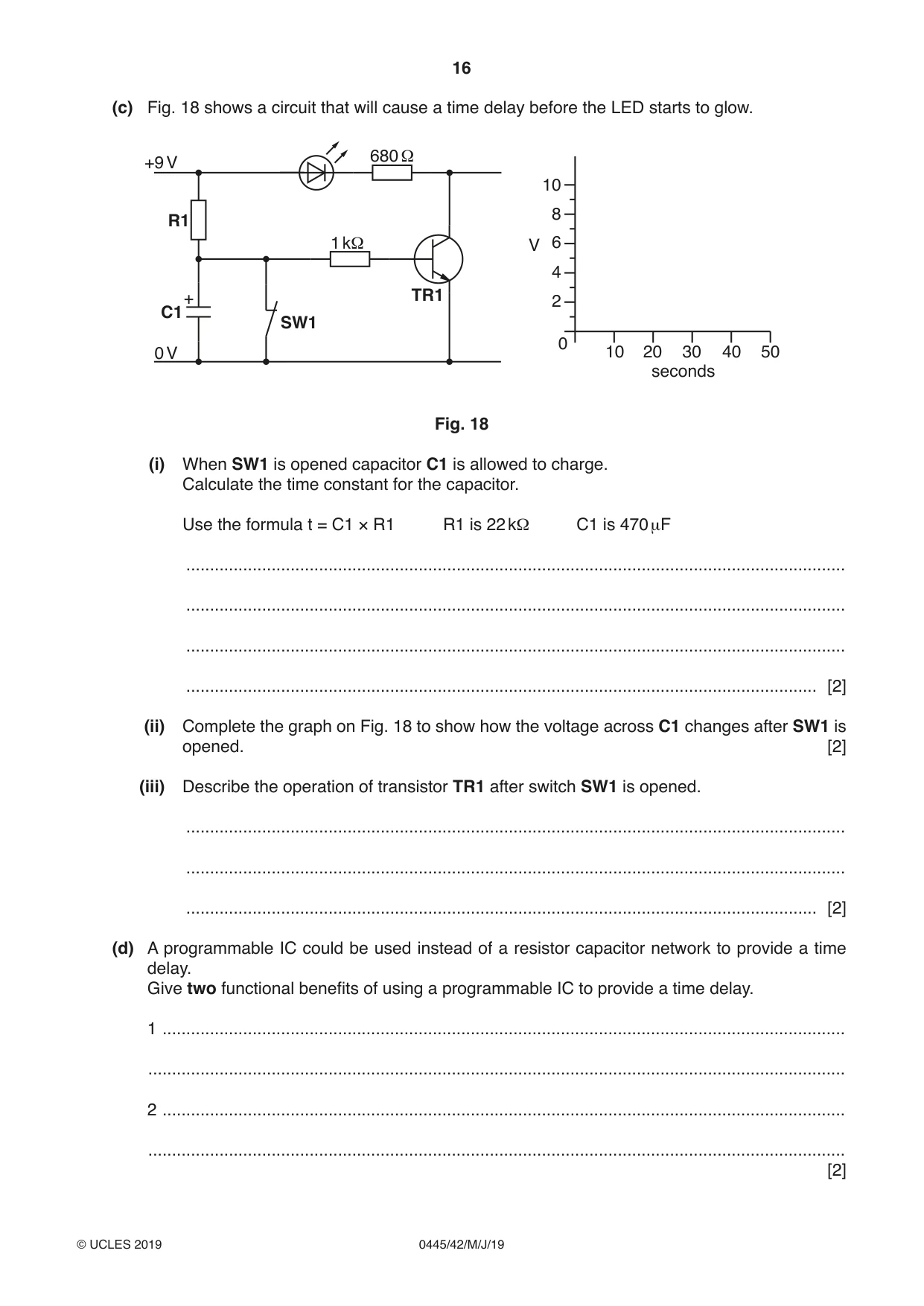
10 (a) A simple electronic circuit is shown in Fig. 15. +12 V X Y Z M 0 V Fig. 15 (i) State the names of components X, Y and Z. X ........................................................................................................................................ Y ........................................................................................................................................ Z ........................................................................................................................................ [3] (ii) Draw on Fig. 15 to show conventional current flow in the circuit. [1] (iii) State the unit used to measure current flow in a circuit. ..................................................................................................................................... [1] (b) Fig. 16 shows part of a sensing circuit. +9 V A B VR1 0 V Fig. 16 (i) State the physical property being sensed by component A. ..................................................................................................................................... [1] (ii) Component A forms one half of a potential divider with VR1. Describe what is meant by a potential divider. ........................................................................................................................................... ..................................................................................................................................... [2] (iii) Calculate the voltage at point B when the resistance of component A is 62 kΩ and VR1 is set to 78 kΩ. R2 Use the formula Vout = × Vin R1 + R2 ........................................................................................................................................... ........................................................................................................................................... ........................................................................................................................................... ..................................................................................................................................... [3] (iv) Draw a voltmeter on Fig. 16 connected to read the voltage at point B. [2] (v) State why the reading on the voltmeter may be different to the calculated voltage. ........................................................................................................................................... ..................................................................................................................................... [1] (vi) Fig. 17 shows the potential divider output connected to an operational amplifier (Op Amp), which will be used to compare two voltages. +9 V – + VR1 0 V Fig. 17 Add two resistors to the circuit to give 4.5 V at the inverting terminal of the Op Amp. State the values of the resistors. [3] (c) Fig. 18 shows a circuit that will cause a time delay before the LED starts to glow. 680 Ω +9 V 10 8 R1 1 kΩ V 6 4 + TR1 2 C1 SW1 0 0 V 10 20 30 40 50 seconds Fig. 18 (i) When SW1 is opened capacitor C1 is allowed to charge. Calculate the time constant for the capacitor. Use the formula t = C1 × R1 R1 is 22 kΩ C1 is 470 μF ........................................................................................................................................... ........................................................................................................................................... ........................................................................................................................................... ..................................................................................................................................... [2] (ii) Complete the graph on Fig. 18 to show how the voltage across C1 changes after SW1 is opened. [2] (iii) Describe the operation of transistor TR1 after switch SW1 is opened. ........................................................................................................................................... ........................................................................................................................................... ..................................................................................................................................... [2] (d) A programmable IC could be used instead of a resistor capacitor network to provide a time delay. Give two functional benefits of using a programmable IC to provide a time delay. 1 ................................................................................................................................................ ................................................................................................................................................... 2 ................................................................................................................................................ ................................................................................................................................................... [2]
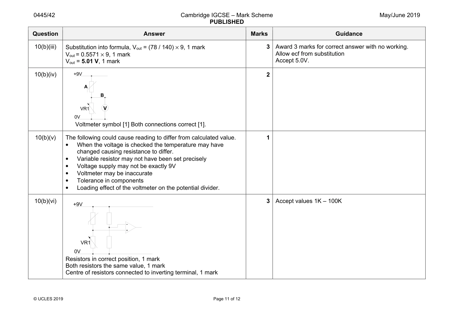
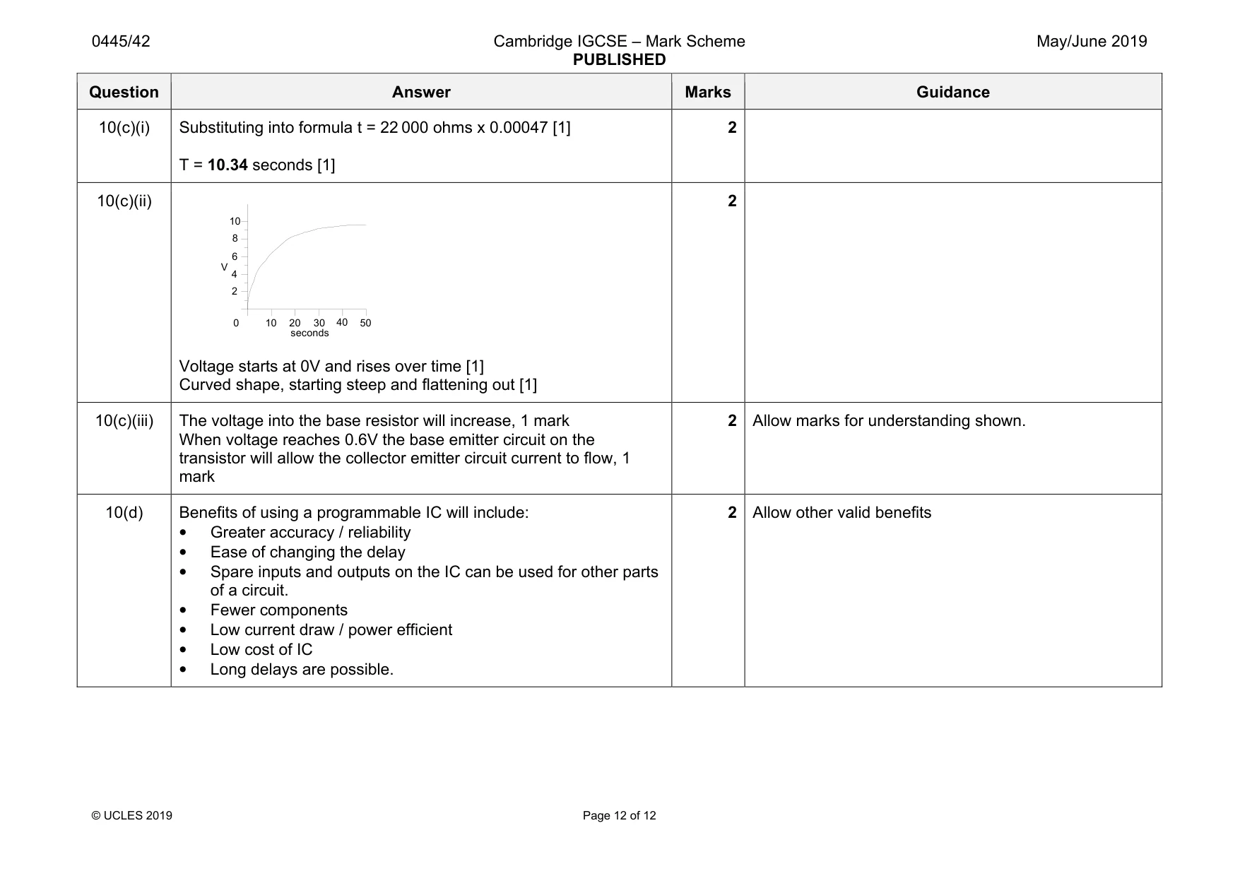
Mark scheme: 10(a)(i) X is a switch Y is a fuse Z is a motor 3 Accept ptm switch or normally open switch. 10(a)(ii) Indication of conventional current should include clockwise arrow(s) with flow from positive to negative. 1 10(a)(iii) Ampere 1 Accept ‘Amp’ 10(b)(i) Change in temperature is being sensed. 1 Accept ‘ heat’ , ‘cold’ or ‘temperature’. 10(b)(ii) Resistors in series connected across a voltage, 1 mark Dividing the voltage in the same ratio as resistor values, 1 mark. 2 Allow mark for understanding shown on second point Question Answer Marks Guidance 10(b)(iii) Substitution into formula, Vout = (78 / 140) × 9, 1 mark Vout = 0.5571 × 9, 1 mark Vout = 5.01 V, 1 mark 3 Award 3 marks for correct answer with no working. Allow ecf from substitution Accept 5.0V. 10(b)(iv) Voltmeter symbol [1] Both connections correct [1]. 2 10(b)(v) The following could cause reading to differ from calculated value. • When the voltage is checked the temperature may have changed causing resistance to differ. • Variable resistor may not have been set precisely • Voltage supply may not be exactly 9V • Voltmeter may be inaccurate • Tolerance in components • Loading effect of the voltmeter on the potential divider. 1 10(b)(vi) Resistors in correct position, 1 mark Both resistors the same value, 1 mark Centre of resistors connected to inverting terminal, 1 mark 3 Accept values 1K – 100K A VR1 B +9V 0V V - + VR1 +9V 0V Question Answer Marks Guidance 10(c)(i) Substituting into formula t = 22 000 ohms x 0.00047 [1] T = 10.34 seconds [1] 2 10(c)(ii) Voltage starts at 0V and rises over time [1] Curved shape, starting steep and flattening out [1] 2 10(c)(iii) The voltage into the base resistor will increase, 1 mark When voltage reaches 0.6V the base emitter circuit on the transistor will allow the collector emitter circuit current to flow, 1 mark 2 Allow marks for understanding shown. 10(d) Benefits of using a programmable IC will include: • Greater accuracy / reliability • Ease of changing the delay • Spare inputs and outputs on the IC can be used for other parts of a circuit. • Fewer components • Low current draw / power efficient • Low cost of IC • Long delays are possible. 2 Allow other valid benefits 2 4 6 8 10 0 50 seconds V 10 20 30 40
What was in this paper
The subtopics covered by these 10 questions, and how many questions each got. Open one in a new tab to see every Cambridge question on it.
What you needed in this session
Cambridge’s own grade thresholds for 2019 May/June, Paper 4 · Variant 2. A higher threshold means an easier paper — the bar moves with how the cohort did.