Cambridge IGCSE Design and Technology 0445 — 2014 Oct/Nov Paper 3 · Variant 3
0445/33/O/N/14 · 50 marks · ≈56 min
The question paper and its mark scheme, free to read here and free to download. This is Cambridge’s own paper, exactly as it was sat.
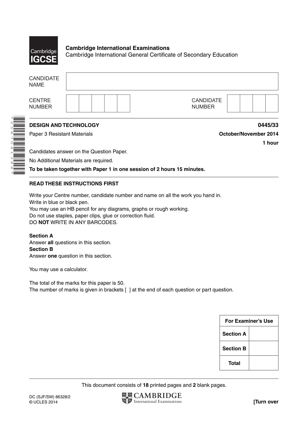
Question paper20 pages




Mark scheme6 pages
Answers below. Sit the paper first if you are practising.
Paper as text
Question paper, page 1
This document consists of 18 printed pages and 2 blank pages. DC (SJF/SW) 86328/2 © UCLES 2014 [Turn over Cambridge International Examinations Cambridge International General Certificate of Secondary Education * 2 5 8 7 0 4 1 3 8 8 * DESIGN AND TECHNOLOGY 0445/33 Paper 3 Resistant Materials October/November 2014 1 hour Candidates answer on the Question Paper. No Additional Materials are required. To be taken together with Paper 1 in one session of 2 hours 15 minutes. READ THESE INSTRUCTIONS FIRST Write your Centre number, candidate number and name on all the work you hand in. Write in blue or black pen. You may use an HB pencil for any diagrams, graphs or rough working. Do not use staples, paper clips, glue or correction fl uid. DO NOT WRITE IN ANY BARCODES. Section A Answer all questions in this section. Section B Answer one question in this section. You may use a calculator. The total of the marks for this paper is 50. The number of marks is given in brackets [ ] at the end of each question or part question. For Examiner’s Use Section A Section B Total
Question paper, page 2
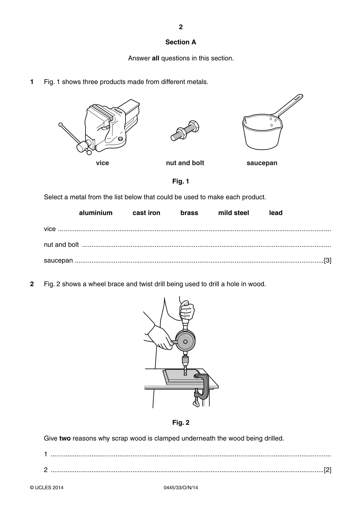
2 0445/33/O/N/14 © UCLES 2014 Section A Answer all questions in this section. 1 Fig. 1 shows three products made from different metals. vice nut and bolt saucepan Fig. 1 Select a metal from the list below that could be used to make each product. aluminium cast iron brass mild steel lead vice … nut and bolt … saucepan …[3] 2 Fig. 2 shows a wheel brace and twist drill being used to drill a hole in wood. Fig. 2 Give two reasons why scrap wood is clamped underneath the wood being drilled. 1 … 2 …[2]
Question paper, page 3
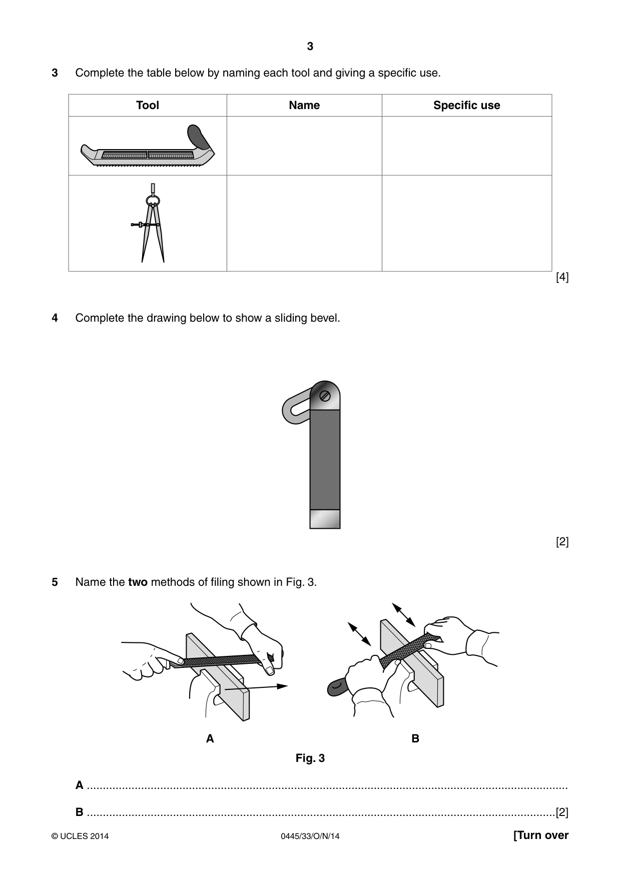
3 0445/33/O/N/14 © UCLES 2014 [Turn over 3 Complete the table below by naming each tool and giving a specific use. Tool Name Specific use [4] 4 Complete the drawing below to show a sliding bevel. [2] 5 Name the two methods of filing shown in Fig. 3. A B Fig. 3 A … B …[2]
Question paper, page 4
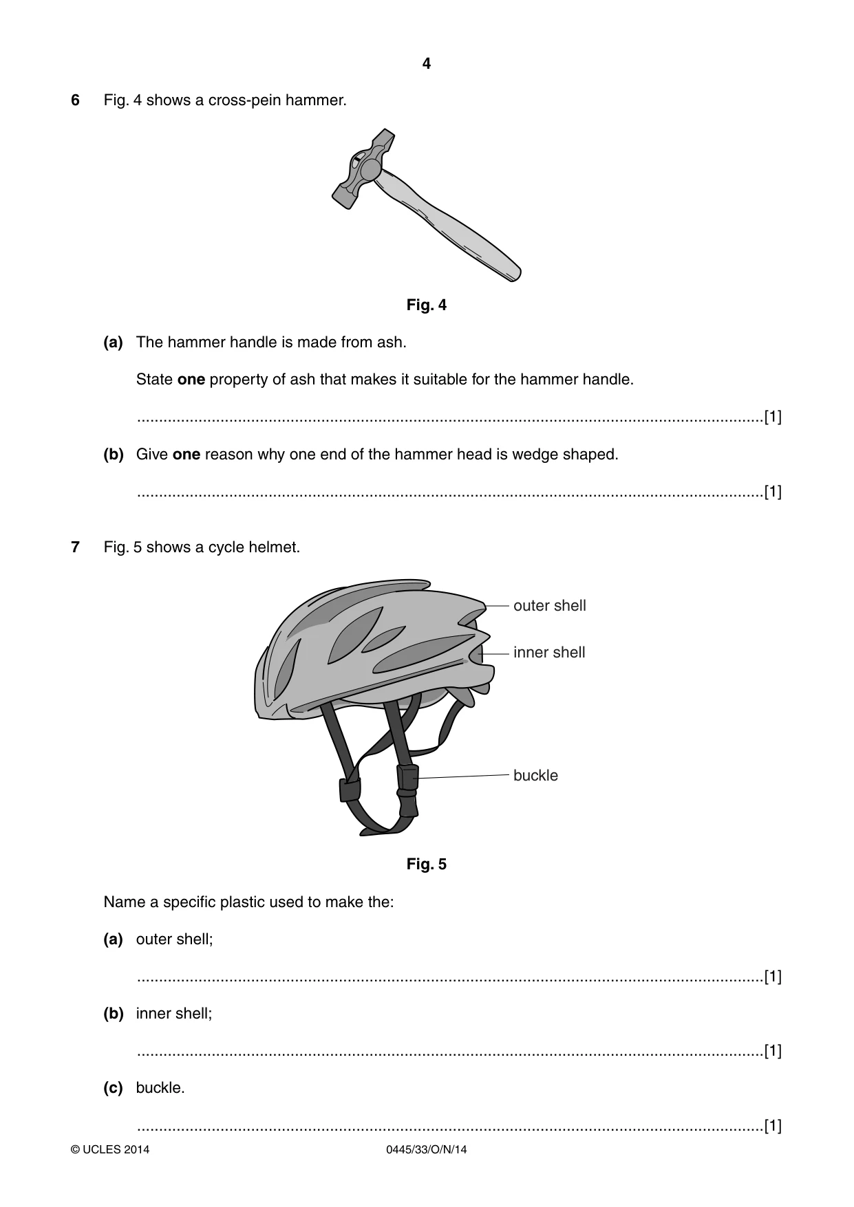
4 0445/33/O/N/14 © UCLES 2014 6 Fig. 4 shows a cross-pein hammer. Fig. 4 (a) The hammer handle is made from ash. State one property of ash that makes it suitable for the hammer handle. …[1] (b) Give one reason why one end of the hammer head is wedge shaped. …[1] 7 Fig. 5 shows a cycle helmet. outer shell inner shell buckle Fig. 5 Name a specific plastic used to make the: (a) outer shell; …[1] (b) inner shell; …[1] (c) buckle. …[1]
Question paper, page 5
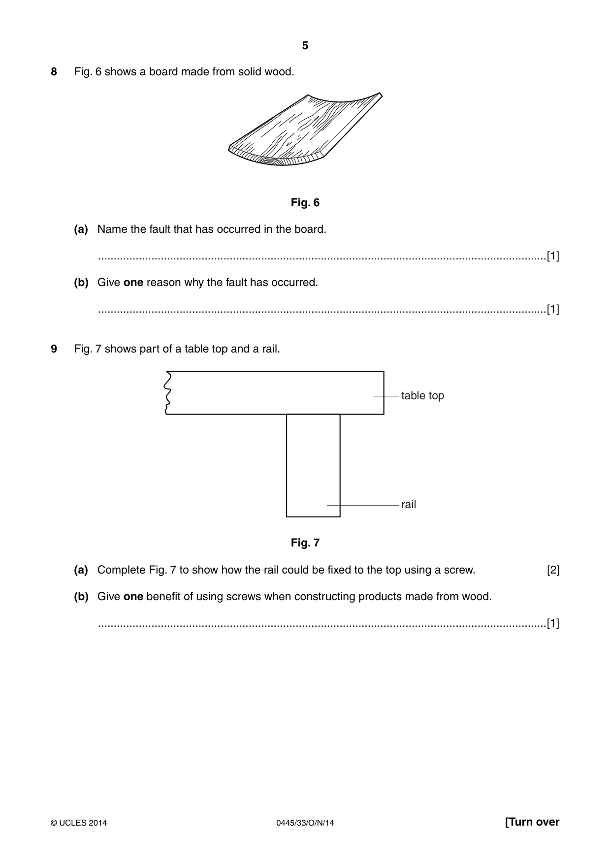
5 0445/33/O/N/14 © UCLES 2014 [Turn over 8 Fig. 6 shows a board made from solid wood. Fig. 6 (a) Name the fault that has occurred in the board. …[1] (b) Give one reason why the fault has occurred. …[1] 9 Fig. 7 shows part of a table top and a rail. table top rail Fig. 7 (a) Complete Fig. 7 to show how the rail could be fixed to the top using a screw. [2] (b) Give one benefit of using screws when constructing products made from wood. …[1]
Question paper, page 6
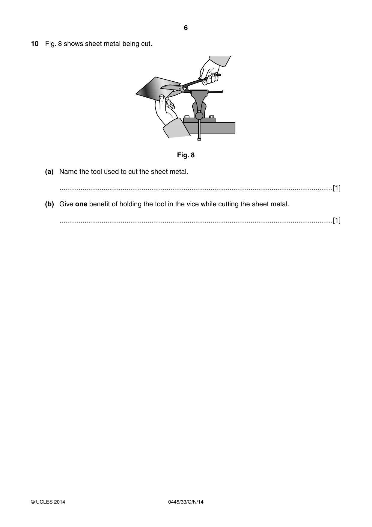
6 0445/33/O/N/14 © UCLES 2014 10 Fig. 8 shows sheet metal being cut. Fig. 8 (a) Name the tool used to cut the sheet metal. …[1] (b) Give one benefit of holding the tool in the vice while cutting the sheet metal. …[1]
Question paper, page 7
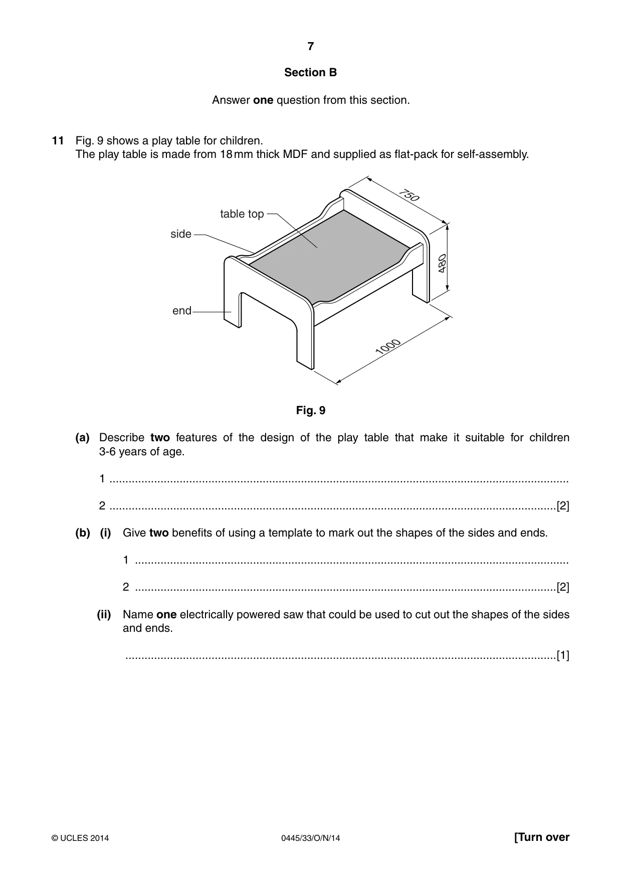
7 0445/33/O/N/14 © UCLES 2014 [Turn over Section B Answer one question from this section. 11 Fig. 9 shows a play table for children. The play table is made from 18 mm thick MDF and supplied as flat-pack for self-assembly. 1000 480 750 end side table top Fig. 9 (a) Describe two features of the design of the play table that make it suitable for children 3-6 years of age. 1 … 2 …[2] (b) (i) Give two benefits of using a template to mark out the shapes of the sides and ends. 1 … 2 …[2] (ii) Name one electrically powered saw that could be used to cut out the shapes of the sides and ends. …[1]
Question paper, page 8
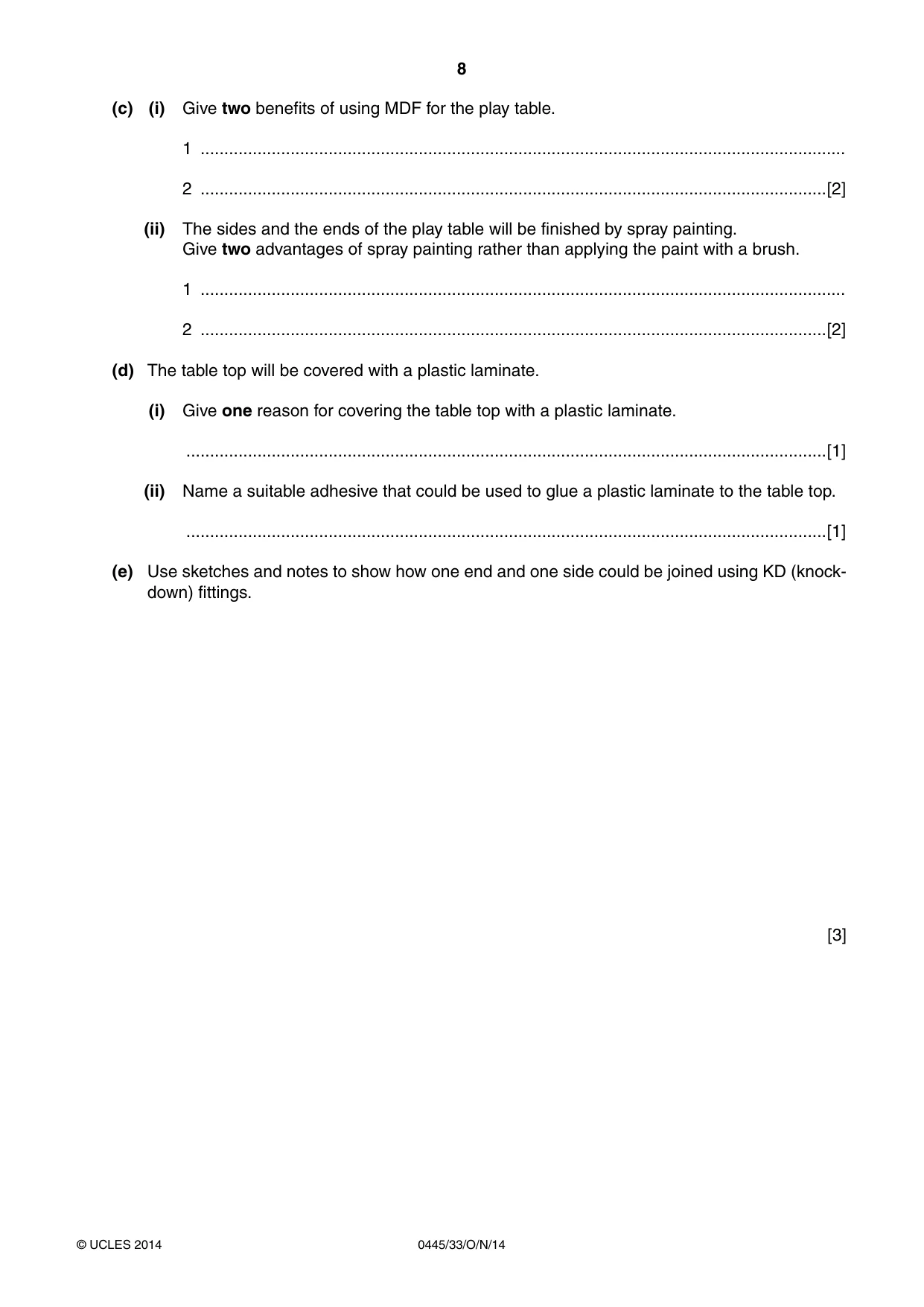
8 0445/33/O/N/14 © UCLES 2014 (c) (i) Give two benefits of using MDF for the play table. 1 … 2 …[2] (ii) The sides and the ends of the play table will be finished by spray painting. Give two advantages of spray painting rather than applying the paint with a brush. 1 … 2 …[2] (d) The table top will be covered with a plastic laminate. (i) Give one reason for covering the table top with a plastic laminate. …[1] (ii) Name a suitable adhesive that could be used to glue a plastic laminate to the table top. …[1] (e) Use sketches and notes to show how one end and one side could be joined using KD (knock- down) fittings. [3]
Question paper, page 9
9 0445/33/O/N/14 © UCLES 2014 [Turn over (f) Use sketches and notes to show how the table top could be supported inside the sides and ends. Your method must allow for removal. [3] (g) Use sketches and notes to show a modification to the play table so that it could be lifted easily. Include details describing how the modification would be carried out in a school workshop. [3]
Question paper, page 10
10 0445/33/O/N/14 © UCLES 2014 (h) The play table could be made using legs and rails made from solid wood. Use sketches and notes to show how the play table could be made from solid wood. Show the sizes of the legs and rails on your sketches. [5]
Question paper, page 11
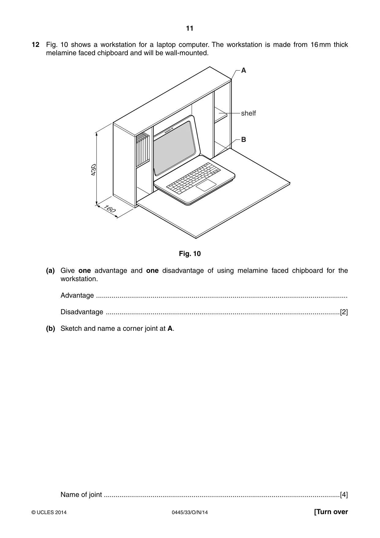
11 0445/33/O/N/14 © UCLES 2014 [Turn over 12 Fig. 10 shows a workstation for a laptop computer. The workstation is made from 16 mm thick melamine faced chipboard and will be wall-mounted. 430 160 shelf A B Fig. 10 (a) Give one advantage and one disadvantage of using melamine faced chipboard for the workstation. Advantage … Disadvantage …[2] (b) Sketch and name a corner joint at A. Name of joint …[4]
Question paper, page 12
12 0445/33/O/N/14 © UCLES 2014 (c) (i) Name two marking out tools, other than a pencil and rule, that could be used to mark out the joint named in (b). 1 … 2 …[2] (ii) Give the specific names of two other tools that could be used to produce the joint named in (b). 1 … 2 …[2] (d) Sketch and name a permanent joint that could be used to join the upright partition to the base at B. Name of joint … [4] (e) Use sketches and notes to show how each shelf could be adjusted to three different heights. [3]
Question paper, page 13
13 0445/33/O/N/14 © UCLES 2014 [Turn over (f) The workstation has a 4 mm thick plywood back. Use sketches and notes to show how the back of the workstation could be strengthened so that it could be screwed to a wall. [3] (g) The design of the workstation could involve the use of a variety of pre-manufactured fittings. (i) Describe how three different pre-manufactured fittings could be used in the construction of the workstation. 1 … 2 … 3 …[3] (ii) Give two advantages of using pre-manufactured fittings. 1 … 2 …[2]
Question paper, page 14
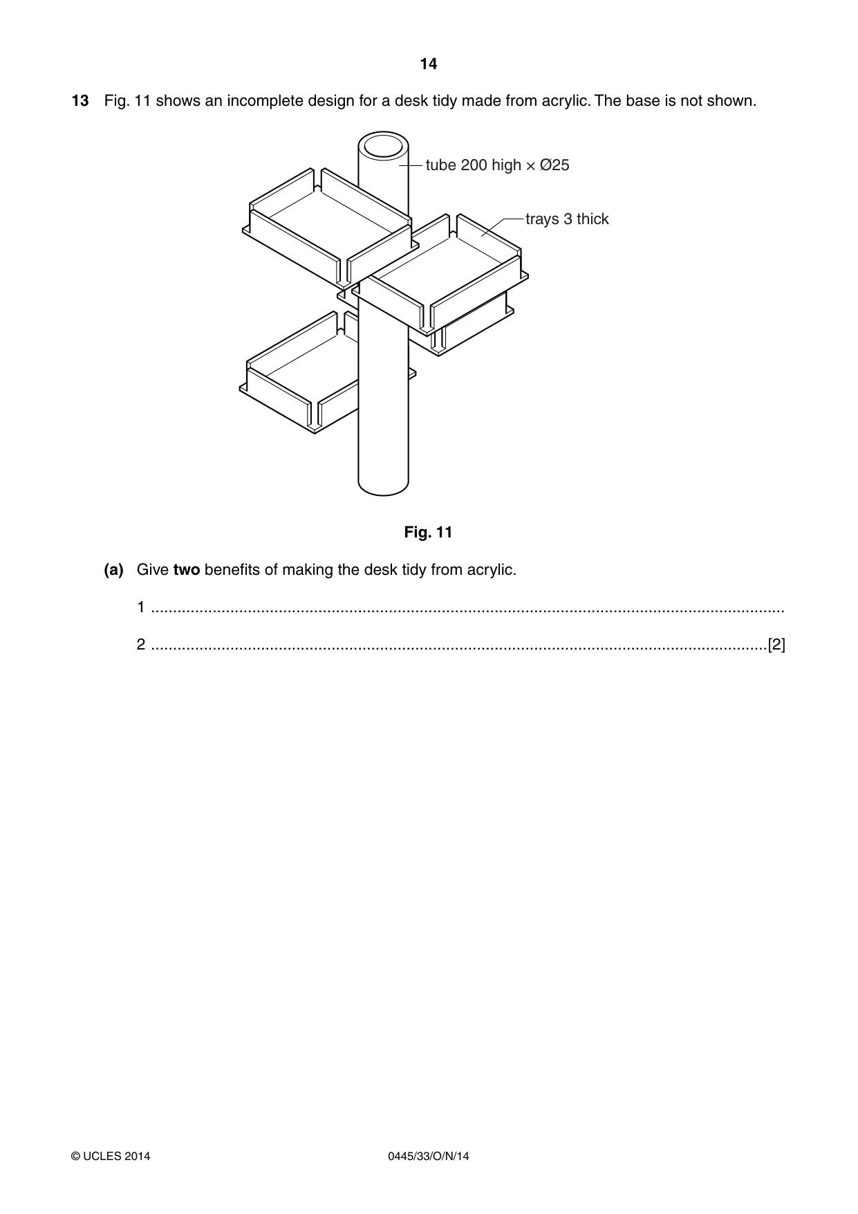
14 0445/33/O/N/14 © UCLES 2014 13 Fig. 11 shows an incomplete design for a desk tidy made from acrylic. The base is not shown. tube 200 high × Ø25 trays 3 thick Fig. 11 (a) Give two benefits of making the desk tidy from acrylic. 1 … 2 …[2]
Question paper, page 15
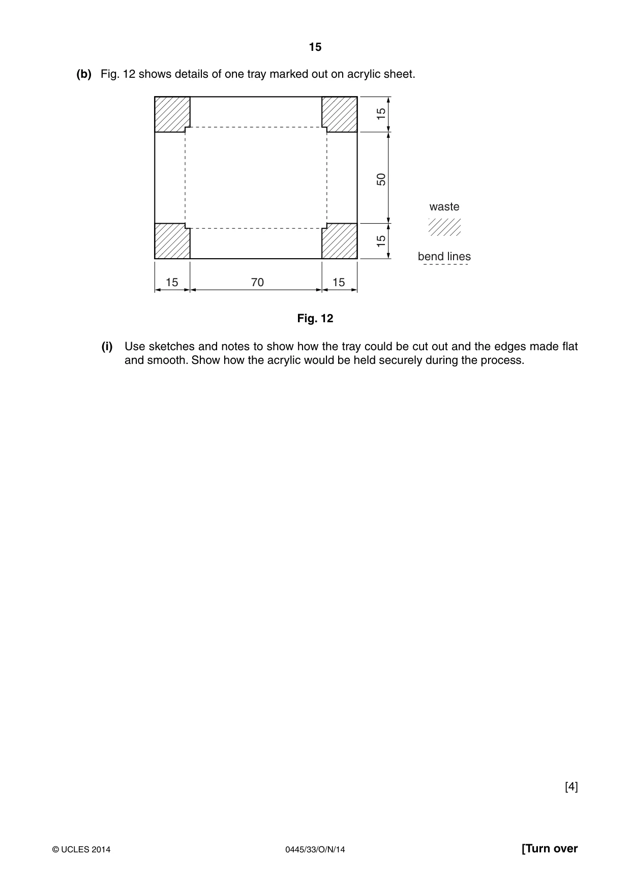
15 0445/33/O/N/14 © UCLES 2014 [Turn over (b) Fig. 12 shows details of one tray marked out on acrylic sheet. 15 15 15 15 50 70 waste bend lines Fig. 12 (i) Use sketches and notes to show how the tray could be cut out and the edges made flat and smooth. Show how the acrylic would be held securely during the process. [4]
Question paper, page 16
16 0445/33/O/N/14 © UCLES 2014 (ii) Use sketches and notes to show how the sides of the tray could be bent to shape. Include the following details: • the method of heating the acrylic; • use of a former; • the method of holding the acrylic while it cools. [5]
Question paper, page 17
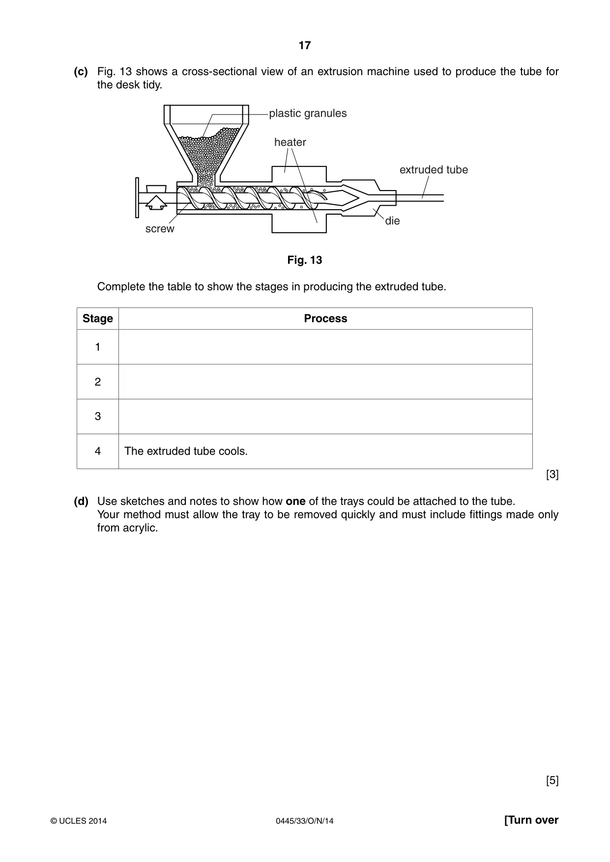
17 0445/33/O/N/14 © UCLES 2014 [Turn over (c) Fig. 13 shows a cross-sectional view of an extrusion machine used to produce the tube for the desk tidy. heater die extruded tube plastic granules screw Fig. 13 Complete the table to show the stages in producing the extruded tube. Stage Process 1 2 3 4 The extruded tube cools. [3] (d) Use sketches and notes to show how one of the trays could be attached to the tube. Your method must allow the tray to be removed quickly and must include fittings made only from acrylic. [5]
Question paper, page 18
18 0445/33/O/N/14 © UCLES 2014 (e) (i) Use sketches and notes to show a design for a base into which the tube will fit permanently. Include details of sizes and construction. [4] (ii) Use sketches and notes to show how you would check that the tube is upright when fitted to the base. [2]
Question paper, page 19
19 0445/33/O/N/14 © UCLES 2014 BLANK PAGE
Question paper, page 20
20 0445/33/O/N/14 © UCLES 2014 Permission to reproduce items where third-party owned material protected by copyright is included has been sought and cleared where possible. Every reasonable effort has been made by the publisher (UCLES) to trace copyright holders, but if any items requiring clearance have unwittingly been included, the publisher will be pleased to make amends at the earliest possible opportunity. Cambridge International Examinations is part of the Cambridge Assessment Group. Cambridge Assessment is the brand name of University of Cambridge Local Examinations Syndicate (UCLES), which is itself a department of the University of Cambridge. BLANK PAGE
Mark scheme, page 1
® IGCSE is the registered trademark of Cambridge International Examinations. CAMBRIDGE INTERNATIONAL EXAMINATIONS Cambridge International General Certificate of Secondary Education MARK SCHEME for the October/November 2014 series 0445 DESIGN AND TECHNOLOGY 0445/33 Paper 3 (Resistant Materials), maximum raw mark 50 This mark scheme is published as an aid to teachers and candidates, to indicate the requirements of the examination. It shows the basis on which Examiners were instructed to award marks. It does not indicate the details of the discussions that took place at an Examiners’ meeting before marking began, which would have considered the acceptability of alternative answers. Mark schemes should be read in conjunction with the question paper and the Principal Examiner Report for Teachers. Cambridge will not enter into discussions about these mark schemes. Cambridge is publishing the mark schemes for the October/November 2014 series for most Cambridge IGCSE®, Cambridge International A and AS Level components and some Cambridge O Level components.
Mark scheme, page 2
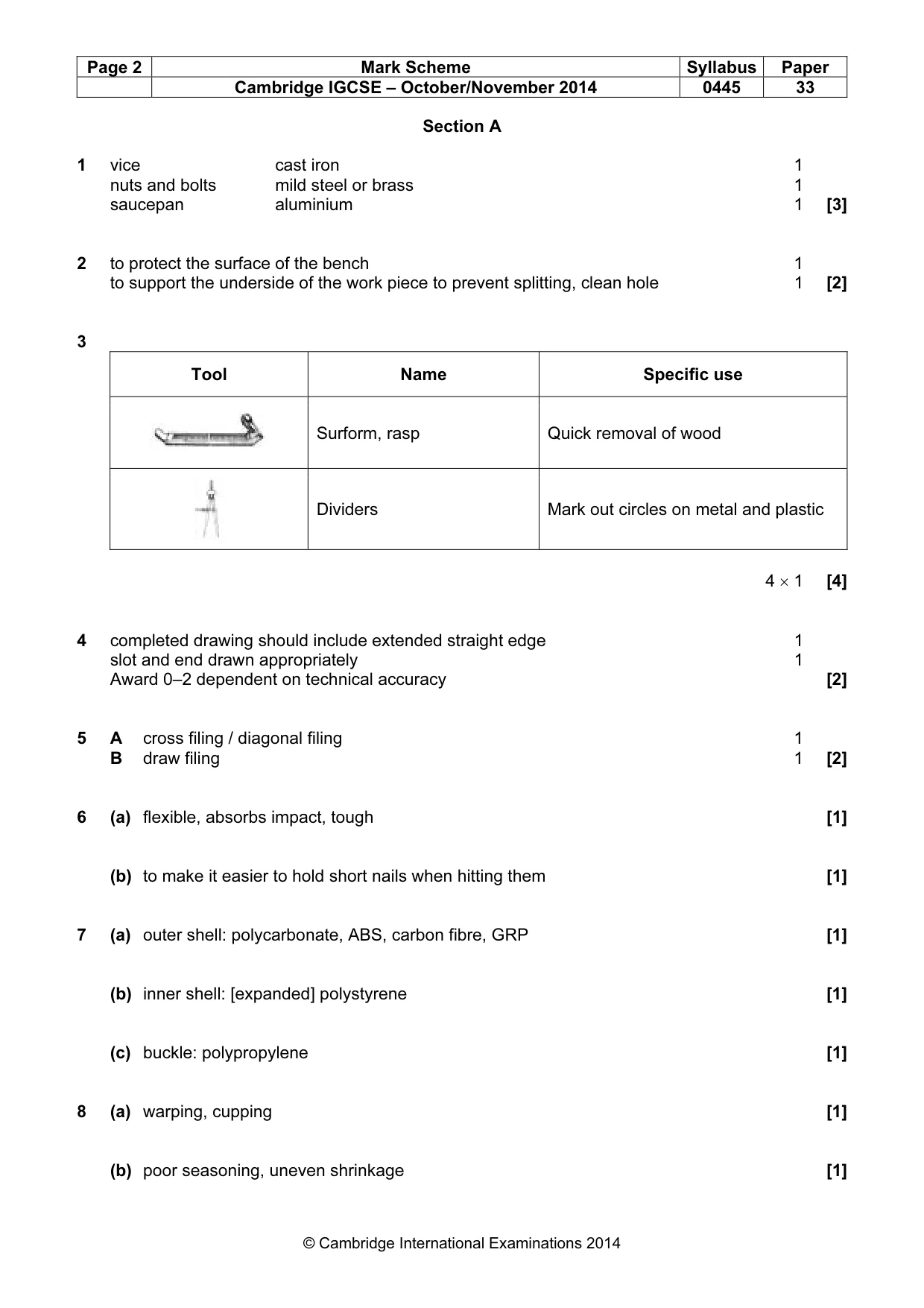
Page 2 Mark Scheme Syllabus Paper Cambridge IGCSE – October/November 2014 0445 33 © Cambridge International Examinations 2014 Section A 1 vice cast iron 1 nuts and bolts mild steel or brass 1 saucepan aluminium 1 [3] 2 to protect the surface of the bench 1 to support the underside of the work piece to prevent splitting, clean hole 1 [2] 3 Tool Name Specific use Surform, rasp Quick removal of wood Dividers Mark out circles on metal and plastic 4 × 1 [4] 4 completed drawing should include extended straight edge 1 slot and end drawn appropriately 1 Award 0–2 dependent on technical accuracy [2] 5 A cross filing / diagonal filing 1 B draw filing 1 [2] 6 (a) flexible, absorbs impact, tough [1] (b) to make it easier to hold short nails when hitting them [1] 7 (a) outer shell: polycarbonate, ABS, carbon fibre, GRP [1] (b) inner shell: [expanded] polystyrene [1] (c) buckle: polypropylene [1] 8 (a) warping, cupping [1] (b) poor seasoning, uneven shrinkage [1]
Mark scheme, page 3
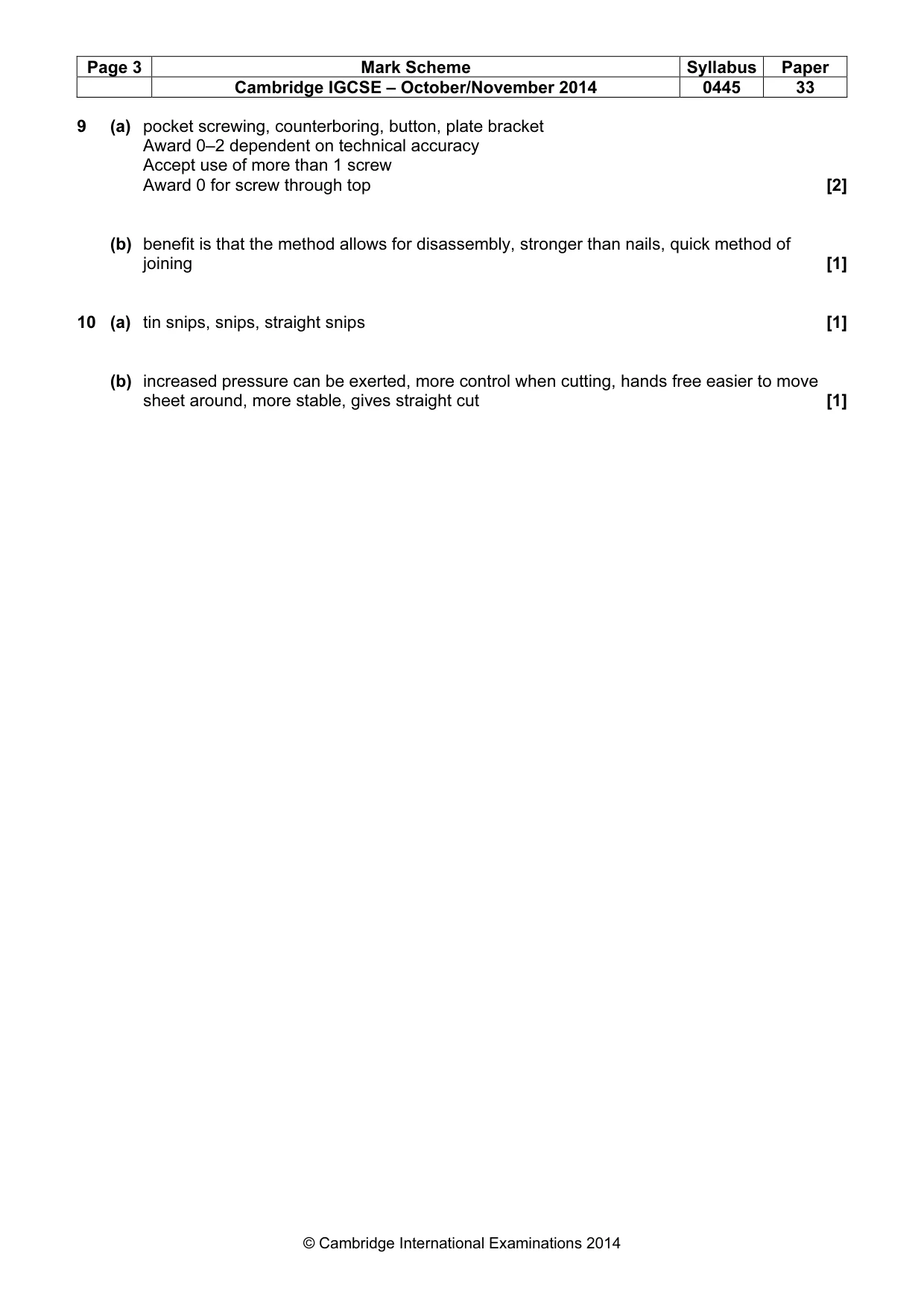
Page 3 Mark Scheme Syllabus Paper Cambridge IGCSE – October/November 2014 0445 33 © Cambridge International Examinations 2014 9 (a) pocket screwing, counterboring, button, plate bracket Award 0–2 dependent on technical accuracy Accept use of more than 1 screw Award 0 for screw through top [2] (b) benefit is that the method allows for disassembly, stronger than nails, quick method of joining [1] 10 (a) tin snips, snips, straight snips [1] (b) increased pressure can be exerted, more control when cutting, hands free easier to move sheet around, more stable, gives straight cut [1]
Mark scheme, page 4
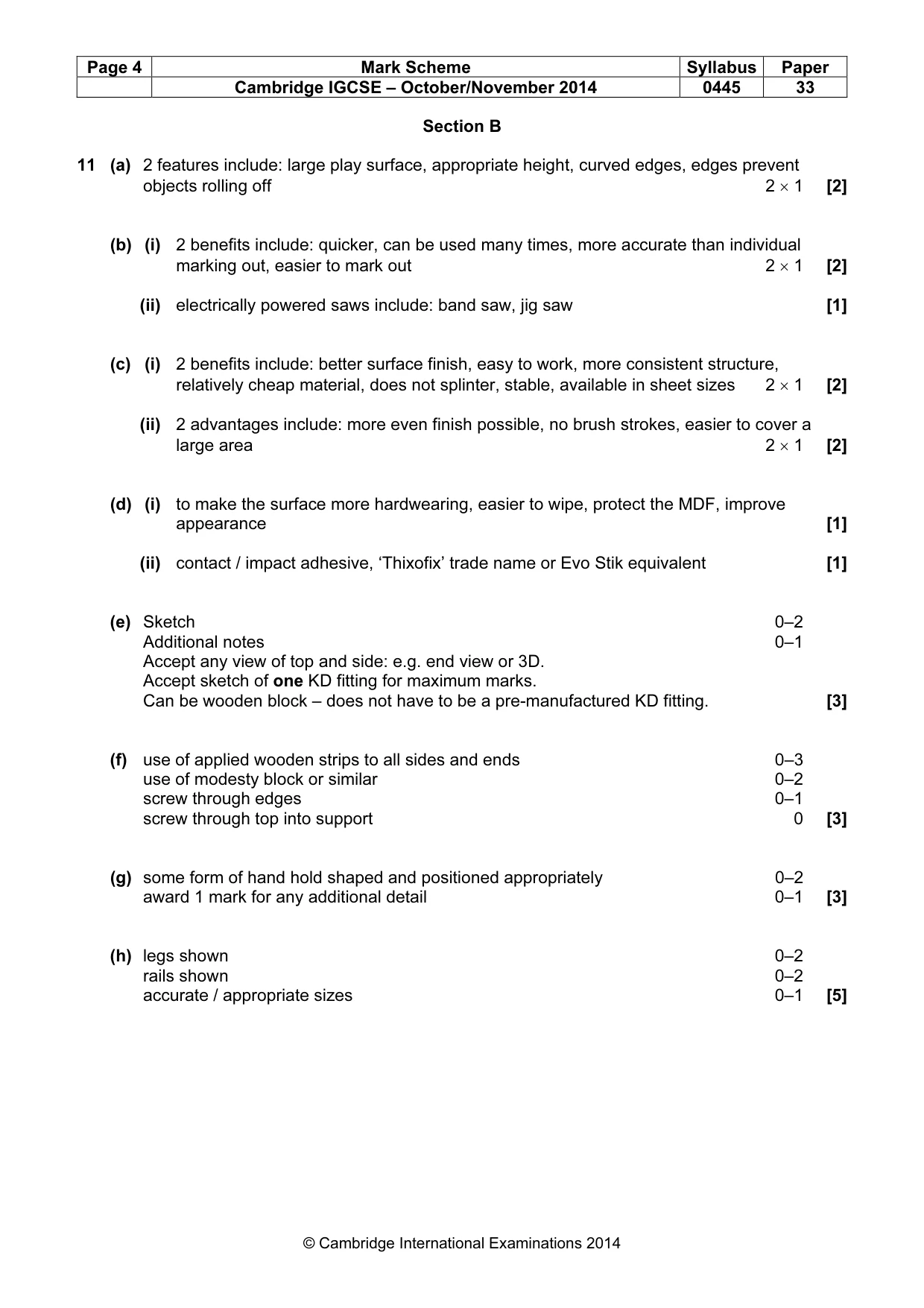
Page 4 Mark Scheme Syllabus Paper Cambridge IGCSE – October/November 2014 0445 33 © Cambridge International Examinations 2014 Section B 11 (a) 2 features include: large play surface, appropriate height, curved edges, edges prevent objects rolling off 2 × 1 [2] (b) (i) 2 benefits include: quicker, can be used many times, more accurate than individual marking out, easier to mark out 2 × 1 [2] (ii) electrically powered saws include: band saw, jig saw [1] (c) (i) 2 benefits include: better surface finish, easy to work, more consistent structure, relatively cheap material, does not splinter, stable, available in sheet sizes 2 × 1 [2] (ii) 2 advantages include: more even finish possible, no brush strokes, easier to cover a large area 2 × 1 [2] (d) (i) to make the surface more hardwearing, easier to wipe, protect the MDF, improve appearance [1] (ii) contact / impact adhesive, ‘Thixofix’ trade name or Evo Stik equivalent [1] (e) Sketch 0–2 Additional notes 0–1 Accept any view of top and side: e.g. end view or 3D. Accept sketch of one KD fitting for maximum marks. Can be wooden block – does not have to be a pre-manufactured KD fitting. [3] (f) use of applied wooden strips to all sides and ends 0–3 use of modesty block or similar 0–2 screw through edges 0–1 screw through top into support 0 [3] (g) some form of hand hold shaped and positioned appropriately 0–2 award 1 mark for any additional detail 0–1 [3] (h) legs shown 0–2 rails shown 0–2 accurate / appropriate sizes 0–1 [5]
Mark scheme, page 5
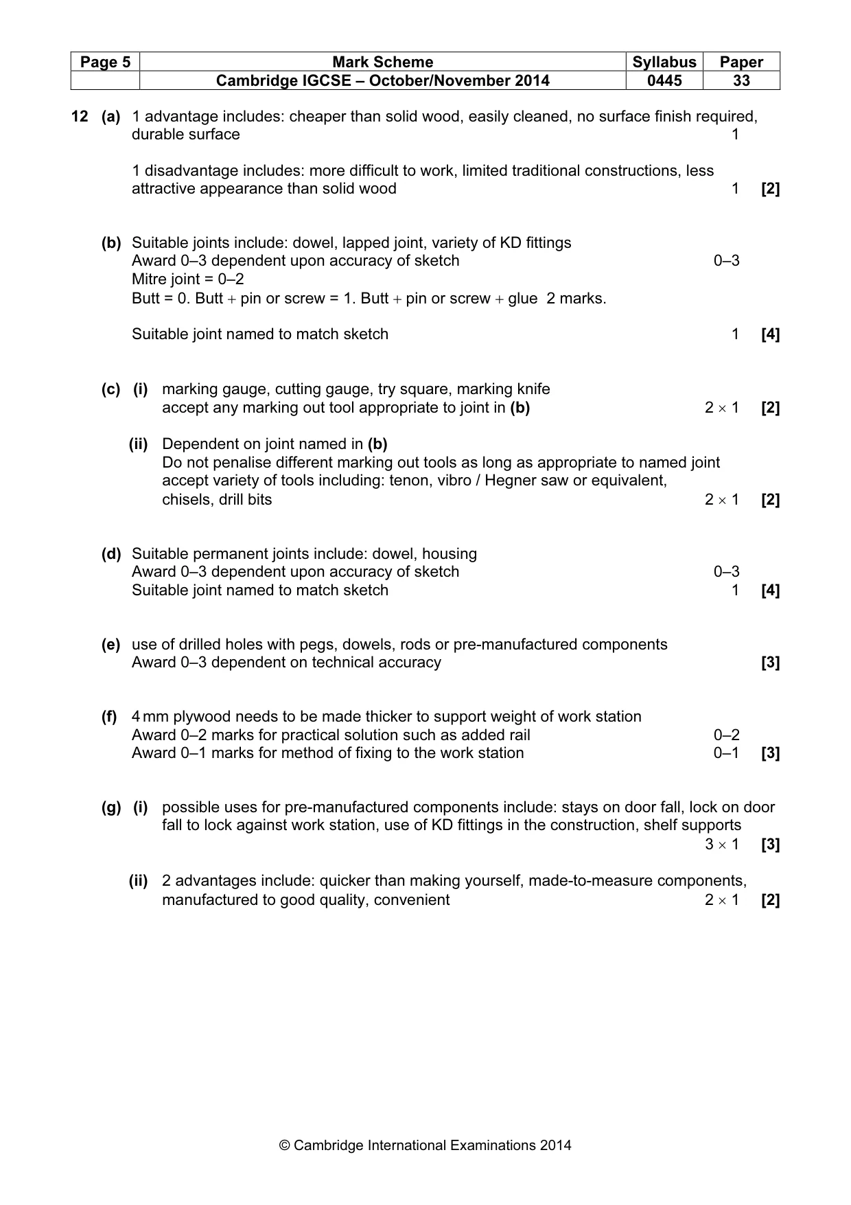
Page 5 Mark Scheme Syllabus Paper Cambridge IGCSE – October/November 2014 0445 33 © Cambridge International Examinations 2014 12 (a) 1 advantage includes: cheaper than solid wood, easily cleaned, no surface finish required, durable surface 1 1 disadvantage includes: more difficult to work, limited traditional constructions, less attractive appearance than solid wood 1 [2] (b) Suitable joints include: dowel, lapped joint, variety of KD fittings Award 0–3 dependent upon accuracy of sketch 0–3 Mitre joint = 0–2 Butt = 0. Butt + pin or screw = 1. Butt + pin or screw + glue 2 marks. Suitable joint named to match sketch 1 [4] (c) (i) marking gauge, cutting gauge, try square, marking knife accept any marking out tool appropriate to joint in (b) 2 × 1 [2] (ii) Dependent on joint named in (b) Do not penalise different marking out tools as long as appropriate to named joint accept variety of tools including: tenon, vibro / Hegner saw or equivalent, chisels, drill bits 2 × 1 [2] (d) Suitable permanent joints include: dowel, housing Award 0–3 dependent upon accuracy of sketch 0–3 Suitable joint named to match sketch 1 [4] (e) use of drilled holes with pegs, dowels, rods or pre-manufactured components Award 0–3 dependent on technical accuracy [3] (f) 4 mm plywood needs to be made thicker to support weight of work station Award 0–2 marks for practical solution such as added rail 0–2 Award 0–1 marks for method of fixing to the work station 0–1 [3] (g) (i) possible uses for pre-manufactured components include: stays on door fall, lock on door fall to lock against work station, use of KD fittings in the construction, shelf supports 3 × 1 [3] (ii) 2 advantages include: quicker than making yourself, made-to-measure components, manufactured to good quality, convenient 2 × 1 [2]
Mark scheme, page 6
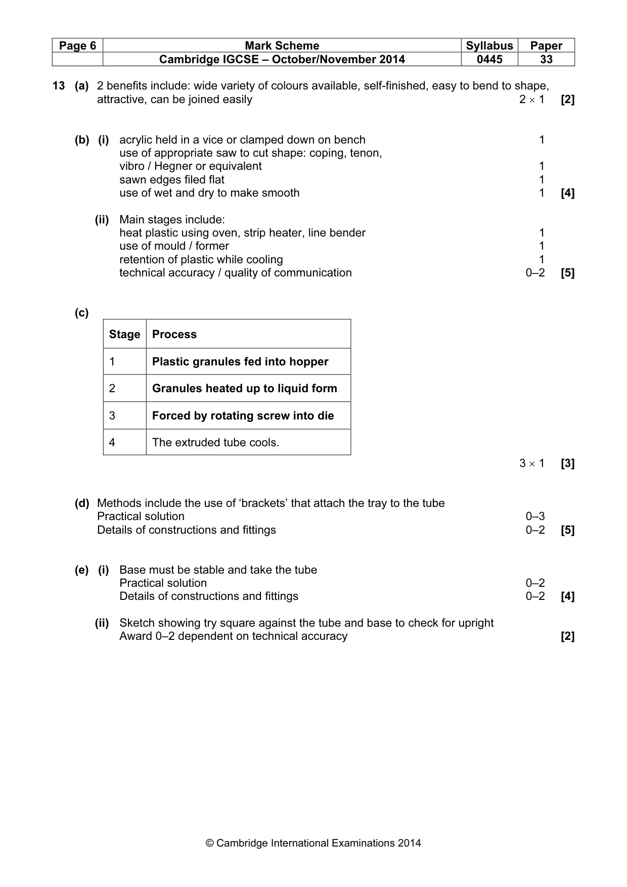
Page 6 Mark Scheme Syllabus Paper Cambridge IGCSE – October/November 2014 0445 33 © Cambridge International Examinations 2014 13 (a) 2 benefits include: wide variety of colours available, self-finished, easy to bend to shape, attractive, can be joined easily 2 × 1 [2] (b) (i) acrylic held in a vice or clamped down on bench 1 use of appropriate saw to cut shape: coping, tenon, vibro / Hegner or equivalent 1 sawn edges filed flat 1 use of wet and dry to make smooth 1 [4] (ii) Main stages include: heat plastic using oven, strip heater, line bender 1 use of mould / former 1 retention of plastic while cooling 1 technical accuracy / quality of communication 0–2 [5] (c) Stage Process 1 Plastic granules fed into hopper 2 Granules heated up to liquid form 3 Forced by rotating screw into die 4 The extruded tube cools. 3 × 1 [3] (d) Methods include the use of ‘brackets’ that attach the tray to the tube Practical solution 0–3 Details of constructions and fittings 0–2 [5] (e) (i) Base must be stable and take the tube Practical solution 0–2 Details of constructions and fittings 0–2 [4] (ii) Sketch showing try square against the tube and base to check for upright Award 0–2 dependent on technical accuracy [2]
What you needed in this session
Cambridge’s own grade thresholds for 2014 Oct/Nov, Paper 3 · Variant 3. A higher threshold means an easier paper — the bar moves with how the cohort did.