Cambridge A Level Physics 9702 — 2015 Oct/Nov Paper 2 · Variant 3
9702/23/O/N/15 · 8 questions · 60 marks · ≈68 min
The question paper and its mark scheme, free to read here and free to download. This is Cambridge’s own paper, exactly as it was sat.
Question paper16 pages
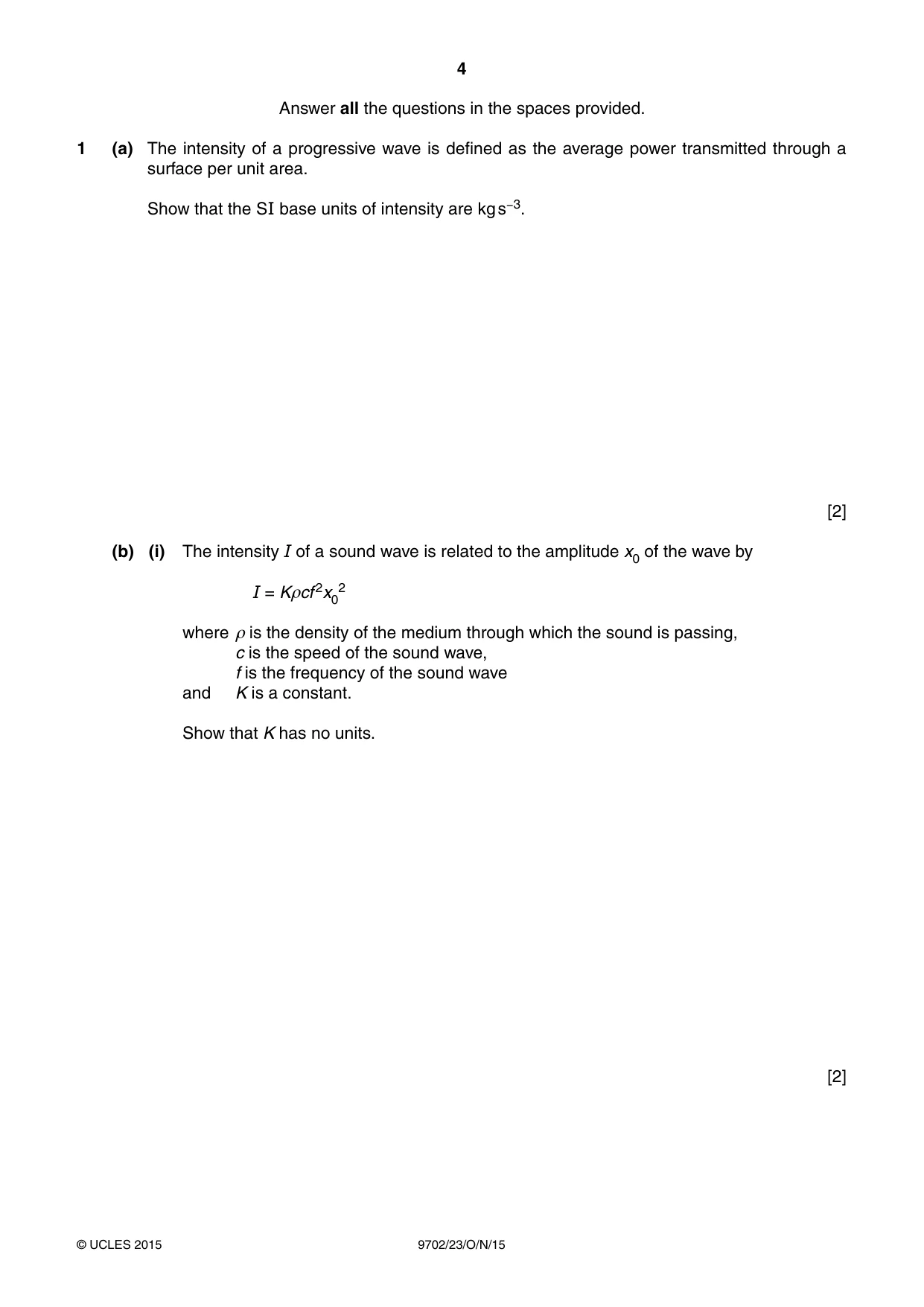
Mark scheme5 pages
Answers below. Sit the paper first if you are practising.
Questions as text
Q1 · The intensity of a progressive wave is defined as the average power transmitted through a…
1 (a) The intensity of a progressive wave is defined as the average power transmitted through a surface per unit area. Show that the SI base units of intensity are kg s−3. [2] (b) (i) The intensity I of a sound wave is related to the amplitude x0 of the wave by I = Kρcf 2x02 where ρ is the density of the medium through which the sound is passing, c is the speed of the sound wave, f is the frequency of the sound wave and K is a constant. Show that K has no units. [2] (ii) Calculate the intensity, in pW m−2, of a sound wave where K = 20, ρ = 1.2 in SI base units, c = 330 in SI base units, f = 260 in SI base units and x0 = 0.24 nm. intensity = ..............................................pW m−2 [3]
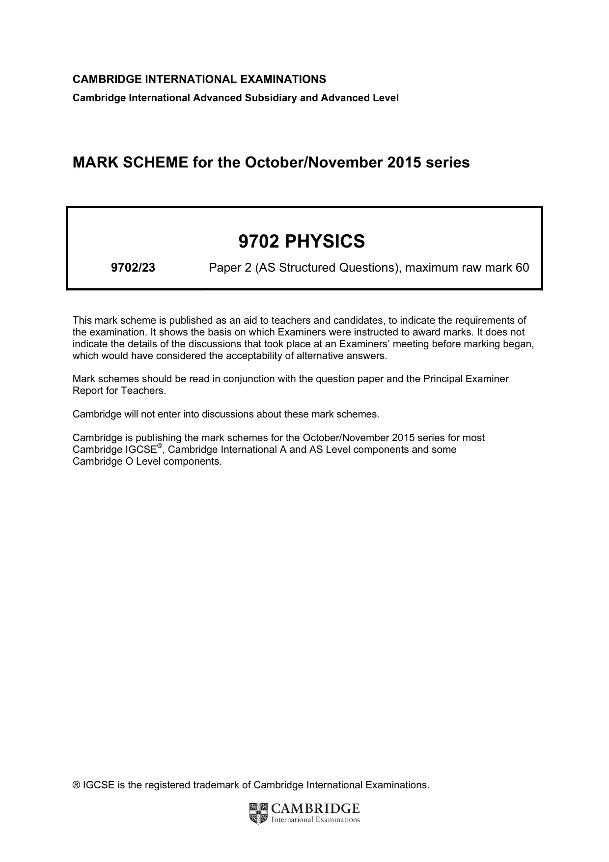
Mark scheme: 1 (a) energy or W: kg m2 s–2 or power or P: kg m2 s–3 M1 intensity or I: kg m2 s–2 m–2 s–1 (from use of energy expression) or kg m2 s–3 m–2 (from use of power expression) indication of simplification to kg s–3 A1 [2] (b) (i) ρ: kg m–3, c: m s–1, f: s–1, x0: m M1 substitution of terms in an appropriate equation and simplification to show K has no units A1 [2] (ii) I = 20 × 1.2 × 330 × (260)2 × (0.24 × 10–9)2 C1 = 3.1 × 10⁻¹¹ (W m–2) C1 = 31 (30.8) pW m–2 A1 [3]
Q2 · A signal generator is connected to two loudspeakers L1 and L2, as shown in Fig
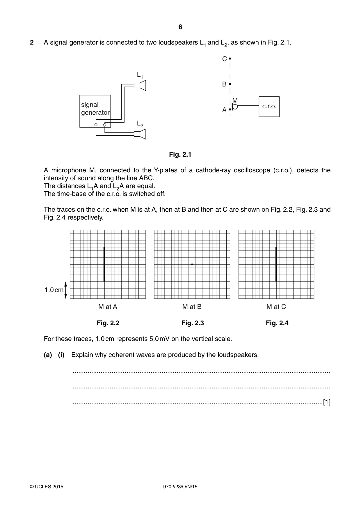
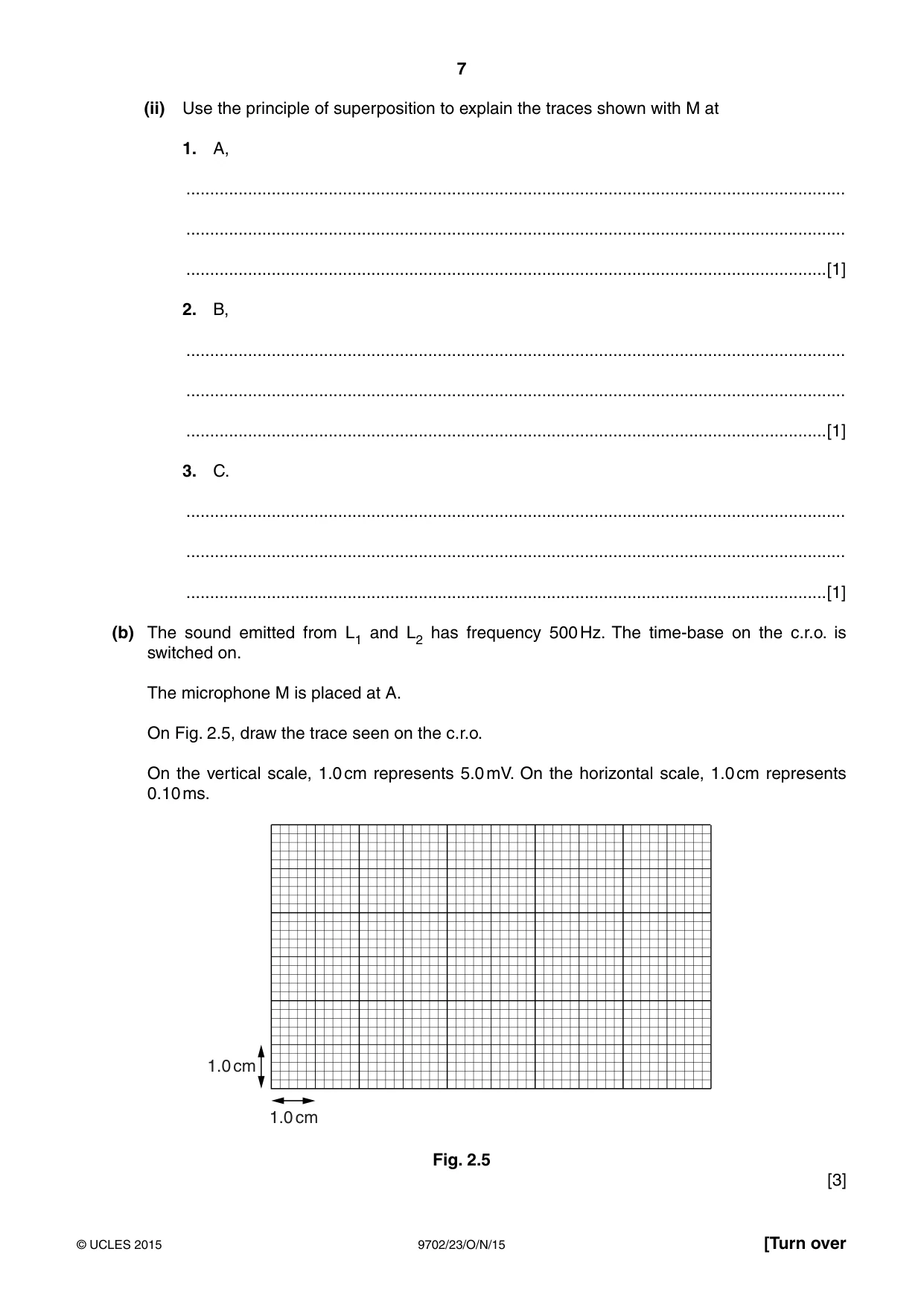
2 A signal generator is connected to two loudspeakers L1 and L2, as shown in Fig. 2.1. C L1 B M signal c.r.o. A generator L2 Fig. 2.1 A microphone M, connected to the Y-plates of a cathode-ray oscilloscope (c.r.o.), detects the intensity of sound along the line ABC. The distances L1A and L2A are equal. The time-base of the c.r.o. is switched off. The traces on the c.r.o. when M is at A, then at B and then at C are shown on Fig. 2.2, Fig. 2.3 and Fig. 2.4 respectively. 1.0 cm M at A M at B M at C Fig. 2.2 Fig. 2.3 Fig. 2.4 For these traces, 1.0 cm represents 5.0 mV on the vertical scale. (a) (i) Explain why coherent waves are produced by the loudspeakers. ........................................................................................................................................... ........................................................................................................................................... .......................................................................................................................................[1] (ii) Use the principle of superposition to explain the traces shown with M at 1. A, ........................................................................................................................................... ........................................................................................................................................... .......................................................................................................................................[1] 2. B, ........................................................................................................................................... ........................................................................................................................................... .......................................................................................................................................[1] 3. C. ........................................................................................................................................... ........................................................................................................................................... .......................................................................................................................................[1] (b) The sound emitted from L1 and L2 has frequency 500 Hz. The time-base on the c.r.o. is switched on. The microphone M is placed at A. On Fig. 2.5, draw the trace seen on the c.r.o. On the vertical scale, 1.0 cm represents 5.0 mV. On the horizontal scale, 1.0 cm represents 0.10 ms. 1.0 cm 1.0 cm Fig. 2.5 [3]
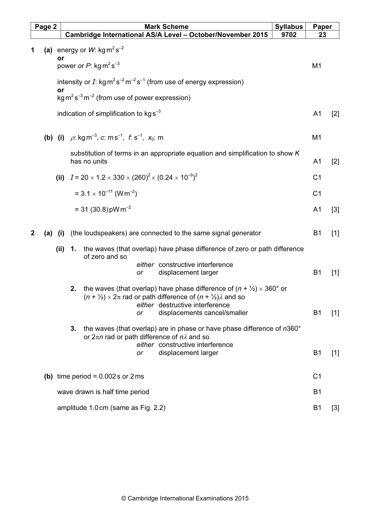
Mark scheme: 2 (a) (i) (the loudspeakers) are connected to the same signal generator B1 [1] (ii) 1. the waves (that overlap) have phase difference of zero or path difference of zero and so either constructive interference or displacement larger B1 [1] 2. the waves (that overlap) have phase difference of (n + ½) × 360° or (n + ½) × 2π rad or path difference of (n + ½)λ and so either destructive interference or displacements cancel/smaller B1 [1] 3. the waves (that overlap) are in phase or have phase difference of n360° or 2πn rad or path difference of nλ and so either constructive interference or displacement larger B1 [1] (b) time period = 0.002 s or 2 ms C1 wave drawn is half time period B1 amplitude 1.0 cm (same as Fig. 2.2) B1 [3] 2
Q3 · A steel ball falls from a platform on a tower to the ground below, as shown in Fig
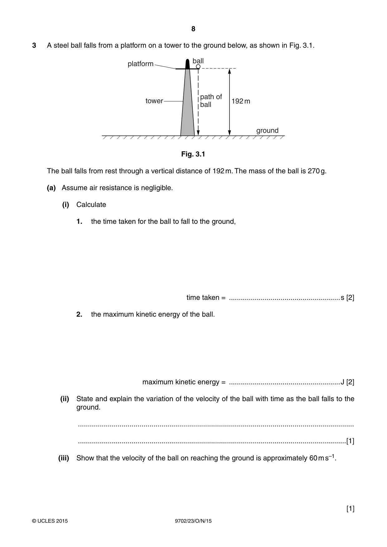
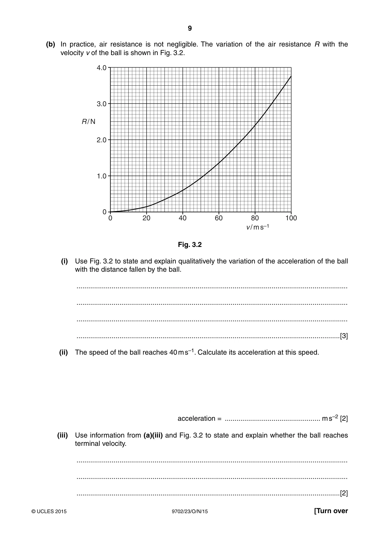
3 A steel ball falls from a platform on a tower to the ground below, as shown in Fig. 3.1. ball platform path of tower 192 m ball ground Fig. 3.1 The ball falls from rest through a vertical distance of 192 m. The mass of the ball is 270 g. (a) Assume air resistance is negligible. (i) Calculate 1. the time taken for the ball to fall to the ground, time taken = ........................................................s [2] 2. the maximum kinetic energy of the ball. maximum kinetic energy = ........................................................J [2] (ii) State and explain the variation of the velocity of the ball with time as the ball falls to the ground. ........................................................................................................................................... .......................................................................................................................................[1] (iii) Show that the velocity of the ball on reaching the ground is approximately 60 m s–1. [1] (b) In practice, air resistance is not negligible. The variation of the air resistance R with the velocity v of the ball is shown in Fig. 3.2. 4.0 3.0 R / N 2.0 1.0 0 0 20 40 60 80 100 v / m s–1 Fig. 3.2 (i) Use Fig. 3.2 to state and explain qualitatively the variation of the acceleration of the ball with the distance fallen by the ball. ........................................................................................................................................... ........................................................................................................................................... ........................................................................................................................................... .......................................................................................................................................[3] (ii) The speed of the ball reaches 40 m s–1. Calculate its acceleration at this speed. acceleration = ................................................. m s–2 [2] (iii) Use information from (a)(iii) and Fig. 3.2 to state and explain whether the ball reaches terminal velocity. ........................................................................................................................................... ........................................................................................................................................... .......................................................................................................................................[2]
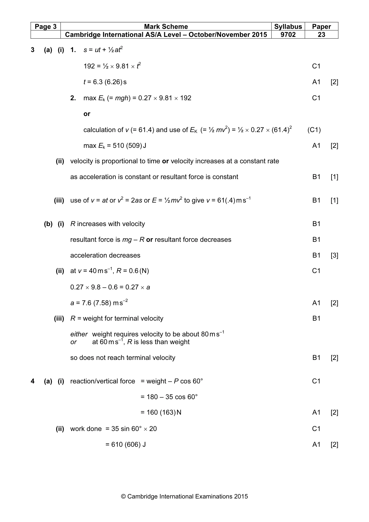
Mark scheme: 3 (a) (i) 1. s = ut + ½ at2 192 = ½ × 9.81 × t2 C1 t = 6.3 (6.26) s A1 [2] 2. max Ek (= mgh) = 0.27 × 9.81 × 192 C1 or calculation of v (= 61.4) and use of EK (= ½ mv2) = ½ × 0.27 × (61.4)2 (C1) max Ek = 510 (509) J A1 [2] (ii) velocity is proportional to time or velocity increases at a constant rate as acceleration is constant or resultant force is constant B1 [1] (iii) use of v = at or v2 = 2as or E = ½ mv2 to give v = 61(.4) m s–1 B1 [1] (b) (i) R increases with velocity B1 resultant force is mg – R or resultant force decreases B1 acceleration decreases B1 [3] (ii) at v = 40 m s–1, R = 0.6 (N) C1 0.27 × 9.8 – 0.6 = 0.27 × a a = 7.6 (7.58) m s–2 A1 [2] (iii) R = weight for terminal velocity B1 either weight requires velocity to be about 80 m s–1 or at 60 m s–1, R is less than weight so does not reach terminal velocity B1 [2]
More questions on Gravitational potential energy and kinetic energy
Q4 · A block is pulled on a horizontal surface by a force P as shown in Fig
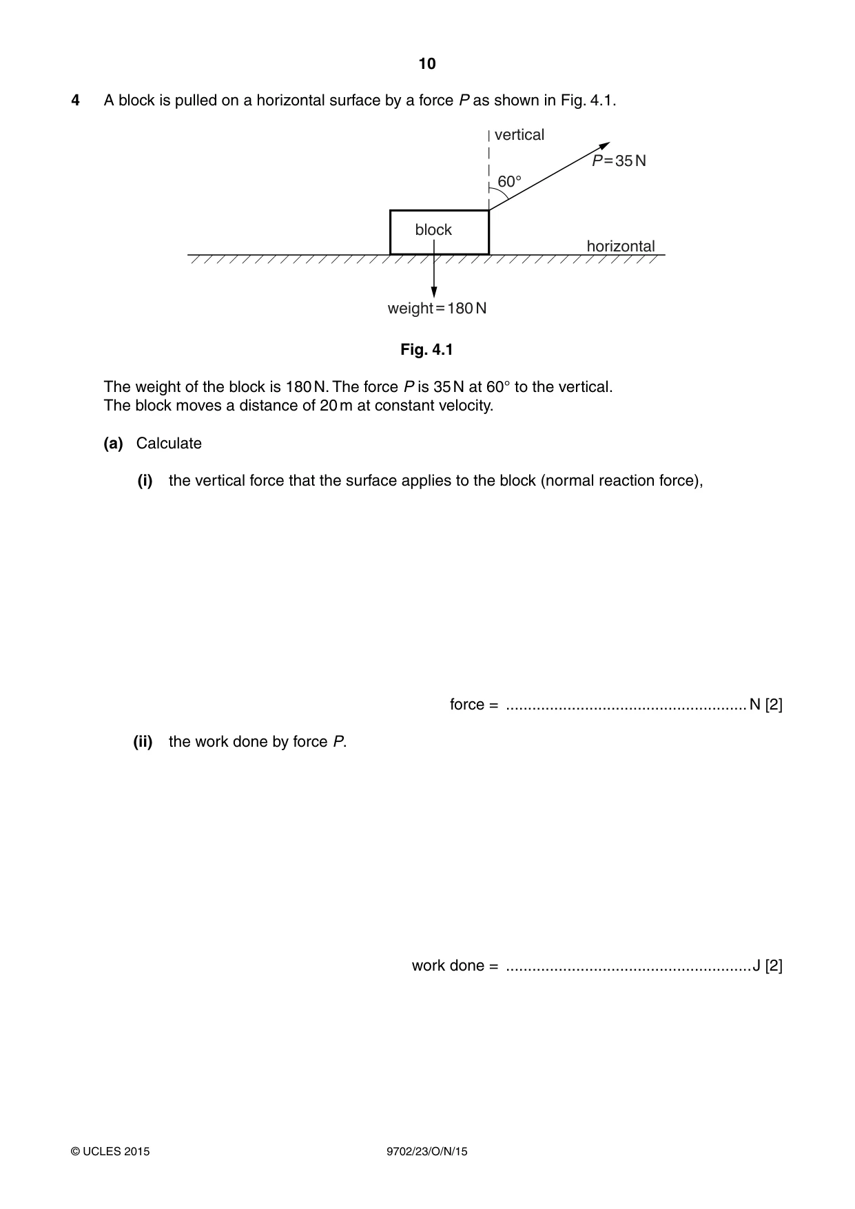
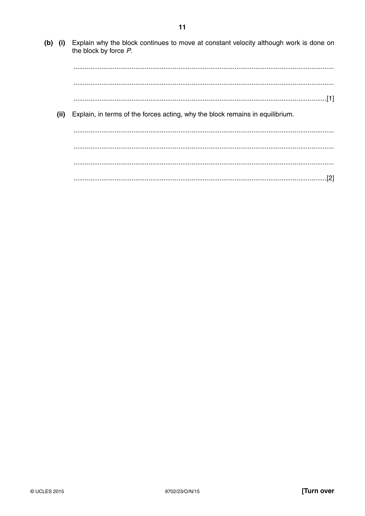
4 A block is pulled on a horizontal surface by a force P as shown in Fig. 4.1. vertical P = 35 N 60° block horizontal weight = 180 N Fig. 4.1 The weight of the block is 180 N. The force P is 35 N at 60° to the vertical. The block moves a distance of 20 m at constant velocity. (a) Calculate (i) the vertical force that the surface applies to the block (normal reaction force), force = .......................................................N [2] (ii) the work done by force P. work done = ........................................................J [2] (b) (i) Explain why the block continues to move at constant velocity although work is done on the block by force P. ........................................................................................................................................... ........................................................................................................................................... .......................................................................................................................................[1] (ii) Explain, in terms of the forces acting, why the block remains in equilibrium. ........................................................................................................................................... ........................................................................................................................................... ........................................................................................................................................... .......................................................................................................................................[2]
Mark scheme: 4 (a) (i) reaction/vertical force = weight – P cos 60° C1 = 180 – 35 cos 60° = 160 (163) N A1 [2] (ii) work done = 35 sin 60° × 20 C1 = 610 (606) J A1 [2] (b) (i) work done by force P = work done against frictional force B1 [1] (ii) horizontal component of P is equal and opposite to frictional force B1 vertical component of P + normal reaction force equal and opposite to weight B1 [2]
Q5 · The I-V characteristic of a semiconductor diode is shown in Fig
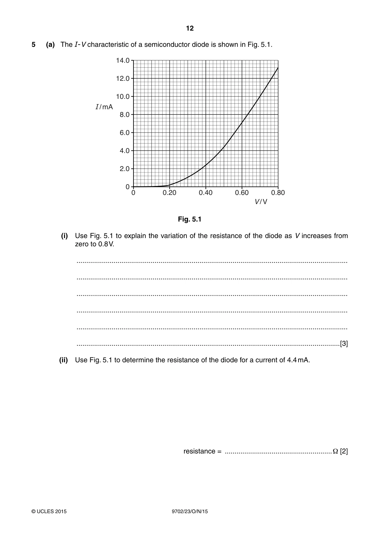
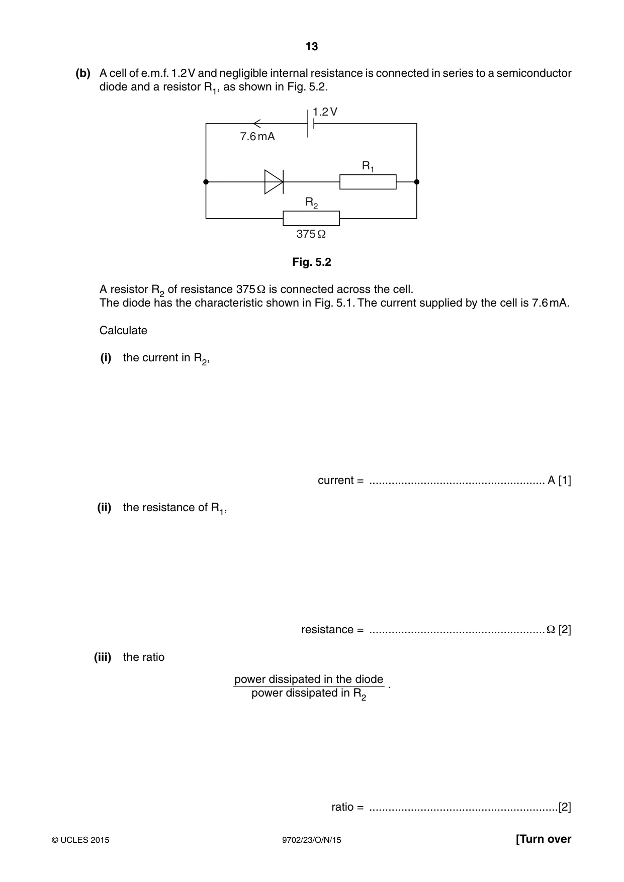
5 (a) The I-V characteristic of a semiconductor diode is shown in Fig. 5.1. 14.0 12.0 10.0 I / mA 8.0 6.0 4.0 2.0 0 0 0.20 0.40 0.60 0.80 V / V Fig. 5.1 (i) Use Fig. 5.1 to explain the variation of the resistance of the diode as V increases from zero to 0.8 V. ........................................................................................................................................... ........................................................................................................................................... ........................................................................................................................................... ........................................................................................................................................... ........................................................................................................................................... .......................................................................................................................................[3] (ii) Use Fig. 5.1 to determine the resistance of the diode for a current of 4.4 mA. resistance = .......................................................Ω [2] (b) A cell of e.m.f. 1.2 V and negligible internal resistance is connected in series to a semiconductor diode and a resistor R1, as shown in Fig. 5.2. 1.2 V 7.6 mA R1 R2 375 1 Fig. 5.2 A resistor R2 of resistance 375 Ω is connected across the cell. The diode has the characteristic shown in Fig. 5.1. The current supplied by the cell is 7.6 mA. Calculate (i) the current in R2, current = ....................................................... A [1] (ii) the resistance of R1, resistance = .......................................................Ω [2] (iii) the ratio power dissipated in the diode . power dissipated in R2 ratio = ...........................................................[2]
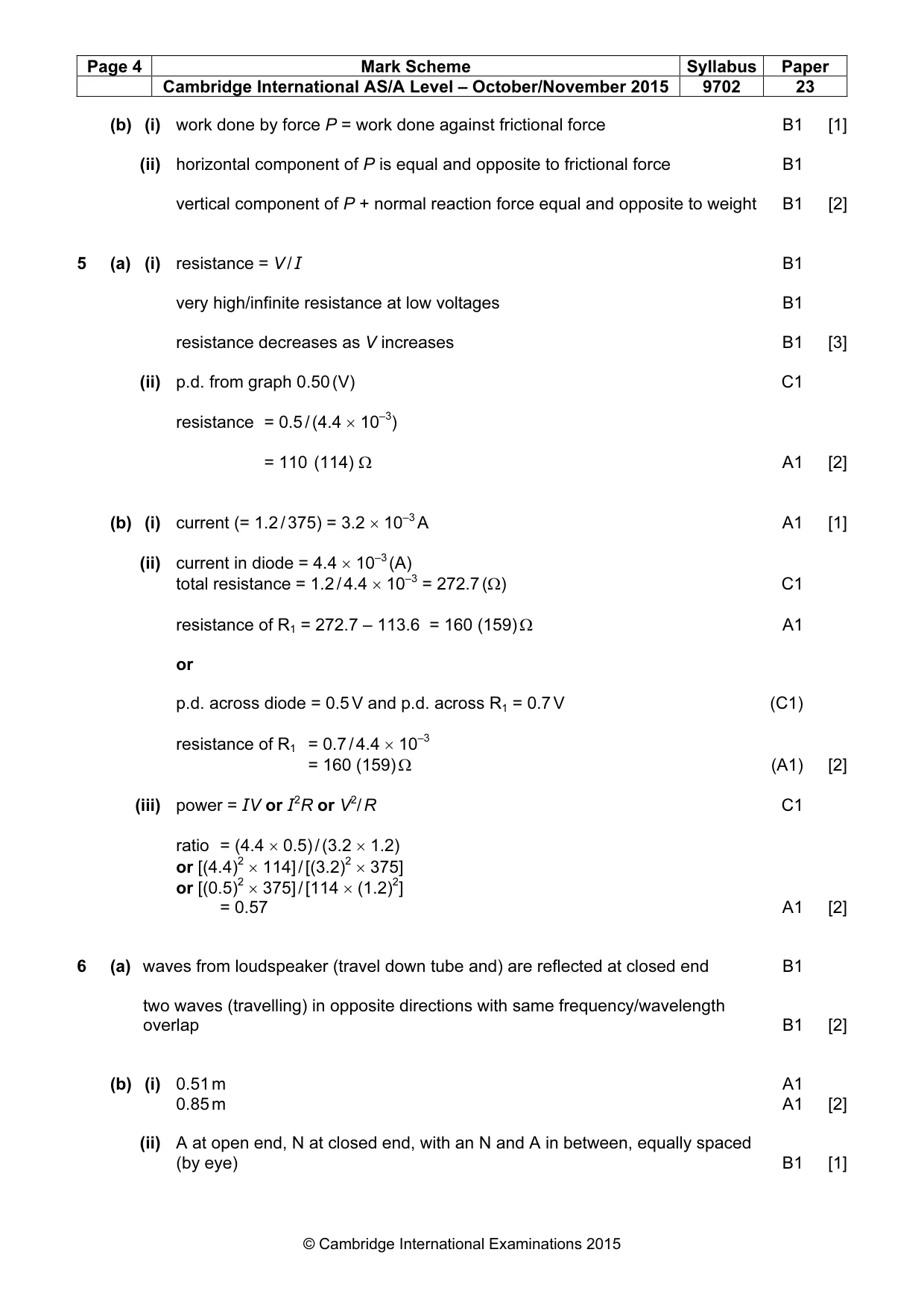
Mark scheme: 5 (a) (i) resistance = V / I B1 very high/infinite resistance at low voltages B1 resistance decreases as V increases B1 [3] (ii) p.d. from graph 0.50 (V) C1 resistance = 0.5 / (4.4 × 10⁻³) = 110 (114) Ω A1 [2] (b) (i) current (= 1.2 / 375) = 3.2 × 10⁻³ A A1 [1] (ii) current in diode = 4.4 × 10⁻³ (A) total resistance = 1.2 / 4.4 × 10–3 = 272.7 (Ω) C1 resistance of R1 = 272.7 – 113.6 = 160 (159) Ω A1 or p.d. across diode = 0.5 V and p.d. across R1 = 0.7 V (C1) resistance of R1 = 0.7 / 4.4 × 10–3 = 160 (159) Ω (A1) [2] (iii) power = IV or I2R or V2/ R C1 ratio = (4.4 × 0.5) / (3.2 × 1.2) or [(4.4)2 × 114] / [(3.2)2 × 375] or [(0.5)2 × 375] / [114 × (1.2)2] = 0.57 A1 [2]
Q6 · An arrangement for producing stationary waves in air in a tube that is closed at one end…
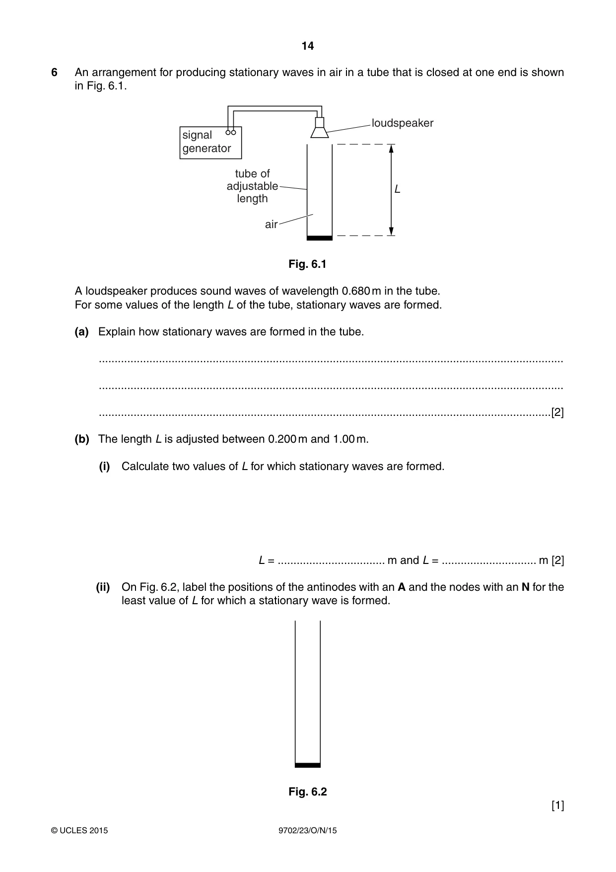
6 An arrangement for producing stationary waves in air in a tube that is closed at one end is shown in Fig. 6.1. loudspeaker signal generator tube of adjustable L length air Fig. 6.1 A loudspeaker produces sound waves of wavelength 0.680 m in the tube. For some values of the length L of the tube, stationary waves are formed. (a) Explain how stationary waves are formed in the tube. ................................................................................................................................................... ................................................................................................................................................... ...............................................................................................................................................[2] (b) The length L is adjusted between 0.200 m and 1.00 m. (i) Calculate two values of L for which stationary waves are formed. L = .................................. m and L = .............................. m [2] (ii) On Fig. 6.2, label the positions of the antinodes with an A and the nodes with an N for the least value of L for which a stationary wave is formed. Fig. 6.2 [1]
Mark scheme: 6 (a) waves from loudspeaker (travel down tube and) are reflected at closed end B1 two waves (travelling) in opposite directions with same frequency/wavelength overlap B1 [2] (b) (i) 0.51 m A1 0.85 m A1 [2] (ii) A at open end, N at closed end, with an N and A in between, equally spaced (by eye) B1 [1]
Q7 · A steel wire of cross-sectional area 15 mm2 has an ultimate tensile stress of 4.5 × 10⁸ N…
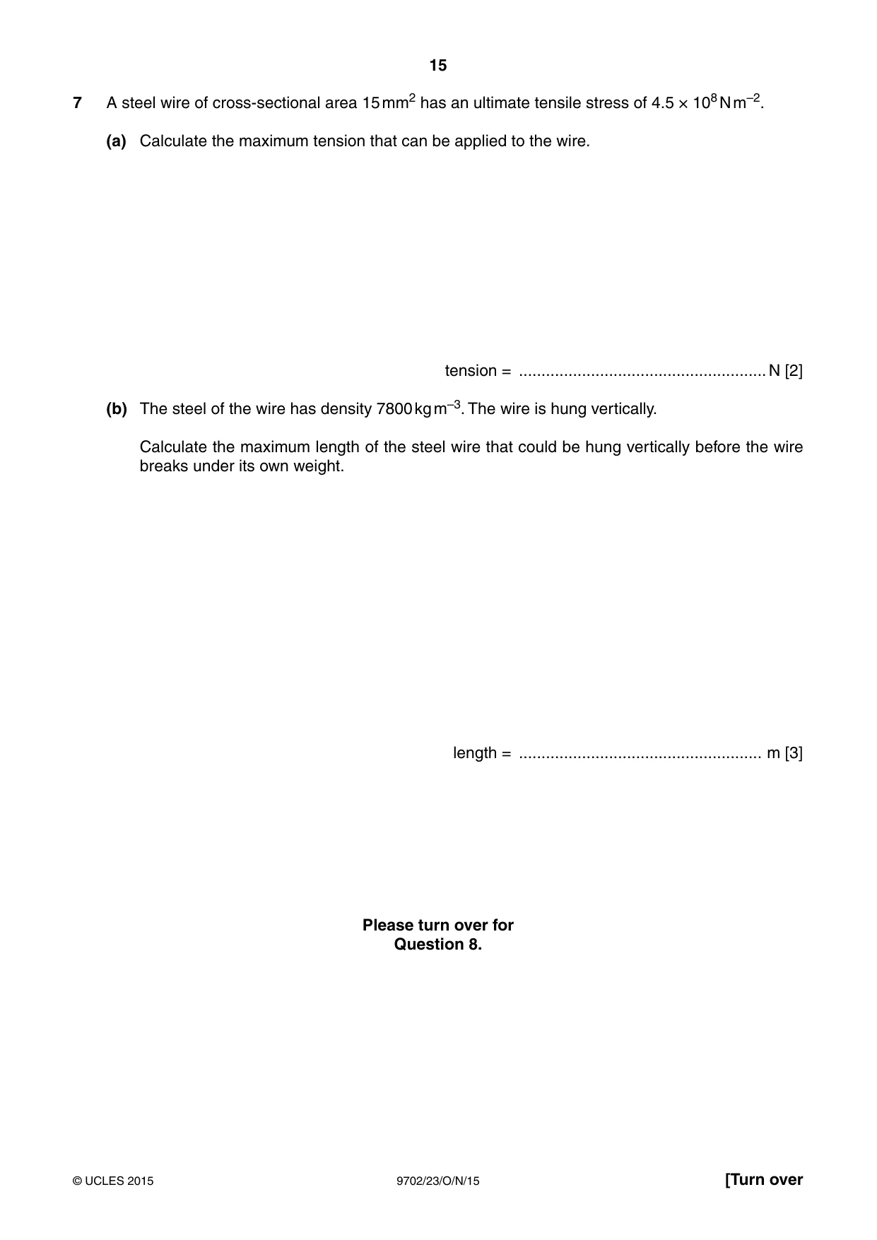
7 A steel wire of cross-sectional area 15 mm2 has an ultimate tensile stress of 4.5 × 10⁸ N m–2. (a) Calculate the maximum tension that can be applied to the wire. tension = .......................................................N [2] (b) The steel of the wire has density 7800 kg m–3. The wire is hung vertically. Calculate the maximum length of the steel wire that could be hung vertically before the wire breaks under its own weight. length = ...................................................... m [3] Please turn over for Question 8.
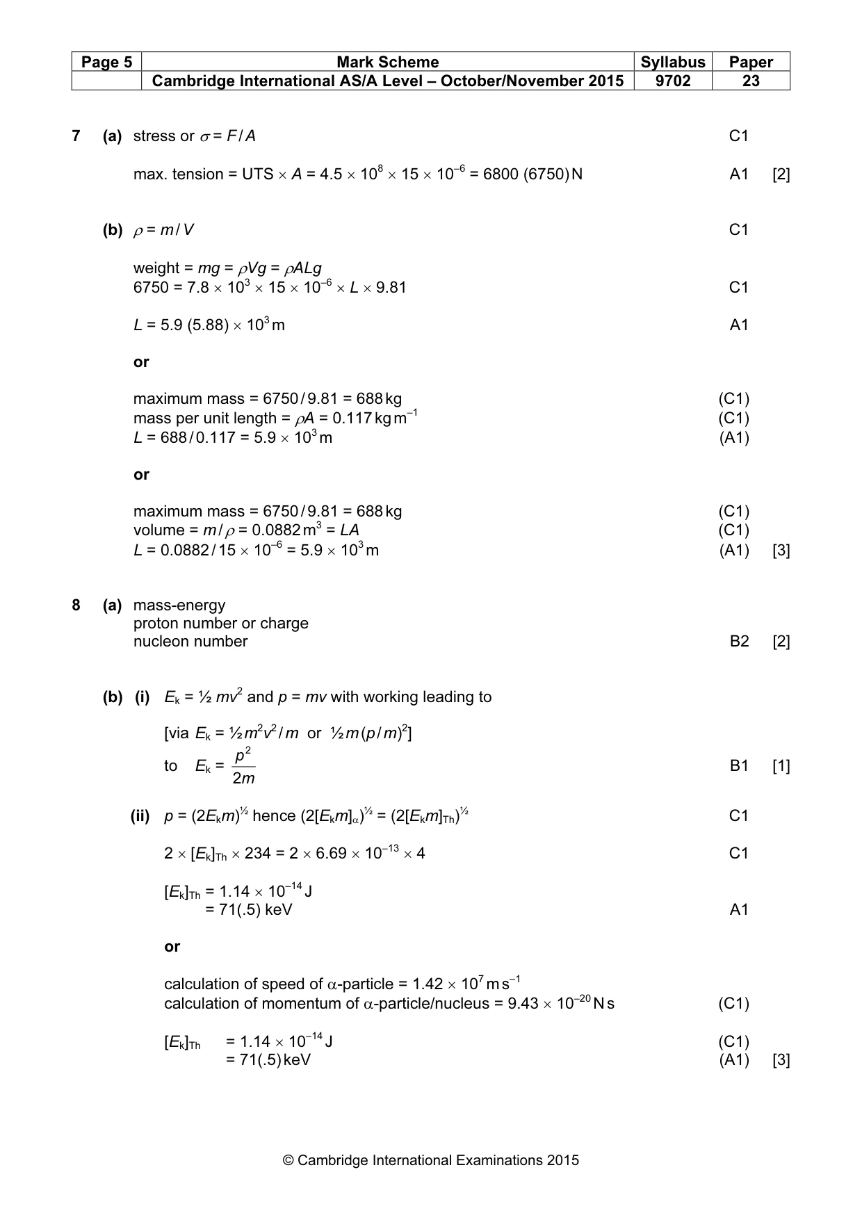
Mark scheme: 7 (a) stress or σ = F / A C1 max. tension = UTS × A = 4.5 × 108 × 15 × 10–6 = 6800 (6750) N A1 [2] (b) ρ = m / V C1 weight = mg = ρVg = ρALg 6750 = 7.8 × 103 × 15 × 10–6 × L × 9.81 C1 L = 5.9 (5.88) × 103 m A1 or maximum mass = 6750 / 9.81 = 688 kg (C1) mass per unit length = ρA = 0.117 kg m–1 (C1) L = 688 / 0.117 = 5.9 × 10³ m (A1) or maximum mass = 6750 / 9.81 = 688 kg (C1) volume = m / ρ = 0.0882 m3 = LA (C1) L = 0.0882 / 15 × 10–6 = 5.9 × 10³ m (A1) [3]
Q8 · State the quantities, other than momentum, that are conserved in a nuclear reaction
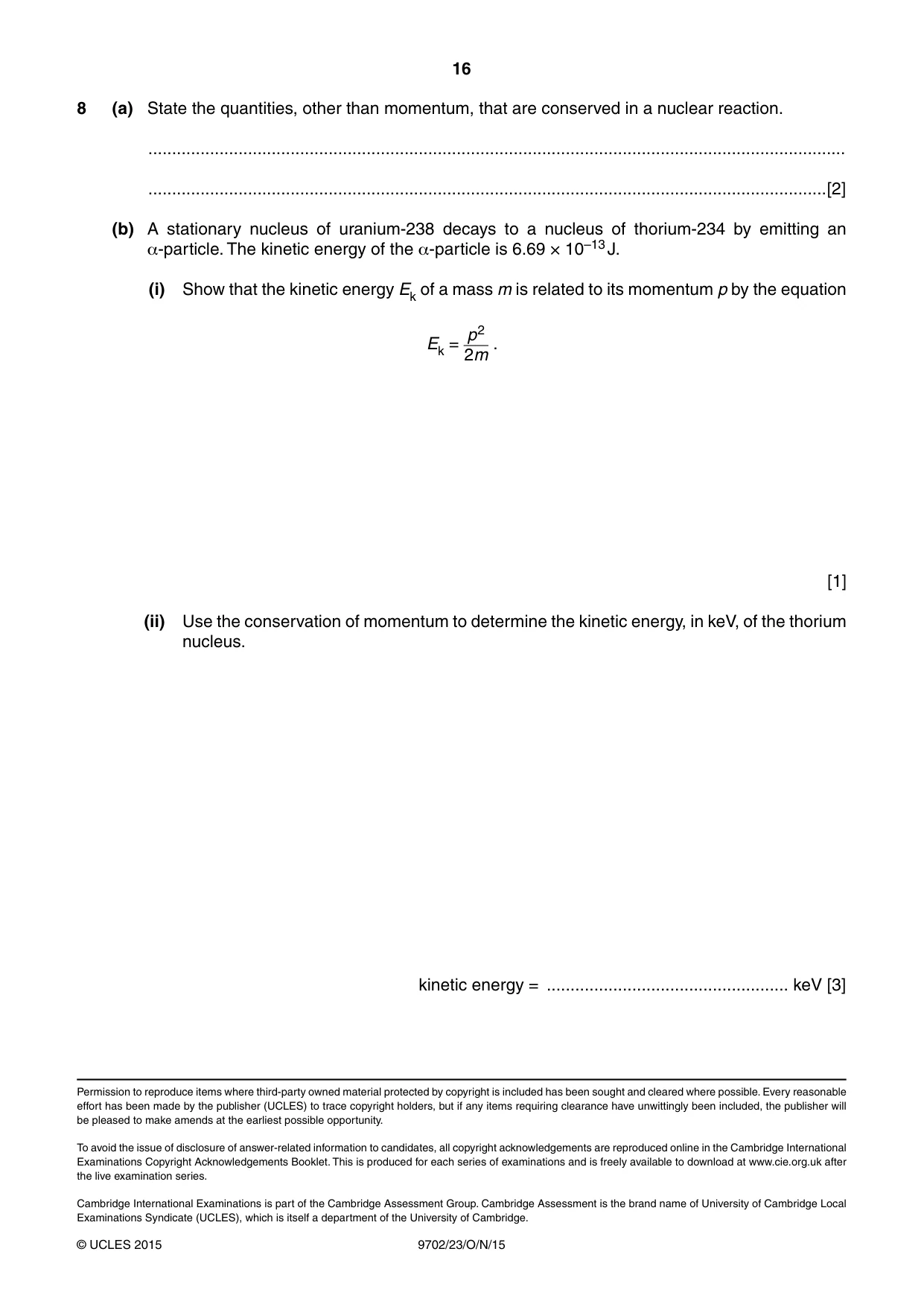
8 (a) State the quantities, other than momentum, that are conserved in a nuclear reaction. ................................................................................................................................................... ...............................................................................................................................................[2] (b) A stationary nucleus of uranium-238 decays to a nucleus of thorium-234 by emitting an α-particle. The kinetic energy of the α-particle is 6.69 × 10⁻¹³ J. (i) Show that the kinetic energy Ek of a mass m is related to its momentum p by the equation p2 Ek = . 2m [1] (ii) Use the conservation of momentum to determine the kinetic energy, in keV, of the thorium nucleus. kinetic energy = ................................................... keV [3]
Mark scheme: 8 (a) mass-energy proton number or charge nucleon number B2 [2] (b) (i) Ek = ½ mv2 and p = mv with working leading to [via Ek = ½ m2v2 / m or ½ m (p / m)2] p 2 to Ek = B1 [1] 2m (ii) p = (2Ekm)½ hence (2[Ekm]α)½ = (2[Ekm]Th)½ C1 2 × [Ek]Th × 234 = 2 × 6.69 × 10–13 × 4 C1 [Ek]Th = 1.14 × 10⁻¹⁴ J = 71(.5) keV A1 or calculation of speed of α-particle = 1.42 × 10⁷ m s–1 calculation of momentum of α-particle/nucleus = 9.43 × 10⁻²⁰ N s (C1) [Ek]Th = 1.14 × 10⁻¹⁴ J (C1) = 71(.5) keV (A1) [3]
What was in this paper
The subtopics covered by these 8 questions, and how many questions each got. Open one in a new tab to see every Cambridge question on it.
What you needed in this session
Cambridge’s own grade thresholds for 2015 Oct/Nov, Paper 2 · Variant 3. A higher threshold means an easier paper — the bar moves with how the cohort did.