Cambridge A Level Physics 9702 — 2023 Oct/Nov Paper 2 · Variant 3
9702/23/O/N/23 · 8 questions · 60 marks · ≈68 min
The question paper and its mark scheme, free to read here and free to download. This is Cambridge’s own paper, exactly as it was sat.
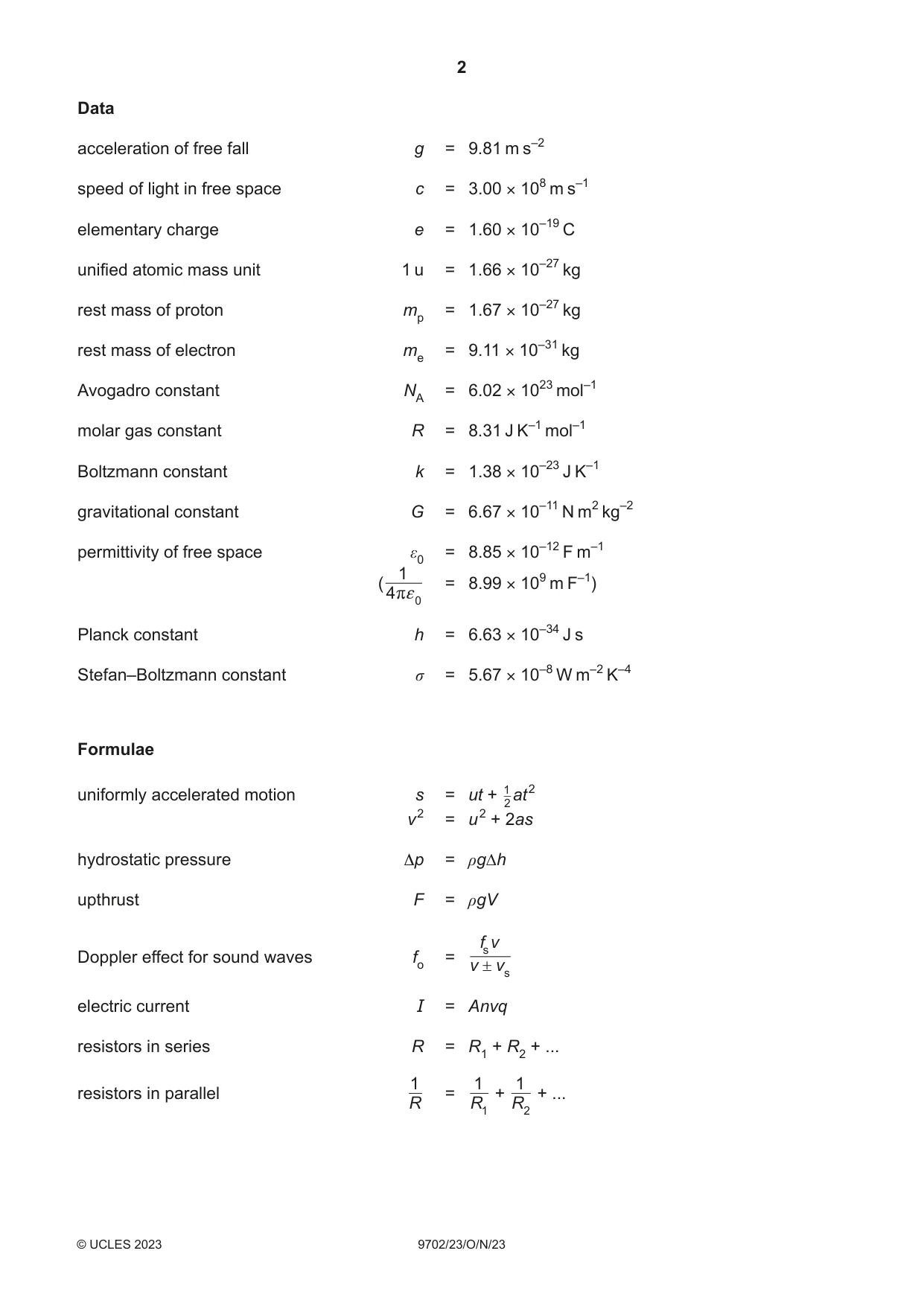
Question paper20 pages



Mark scheme12 pages
Answers below. Sit the paper first if you are practising.
Questions as text
Q1 · Table 1.1 lists some physical quantities
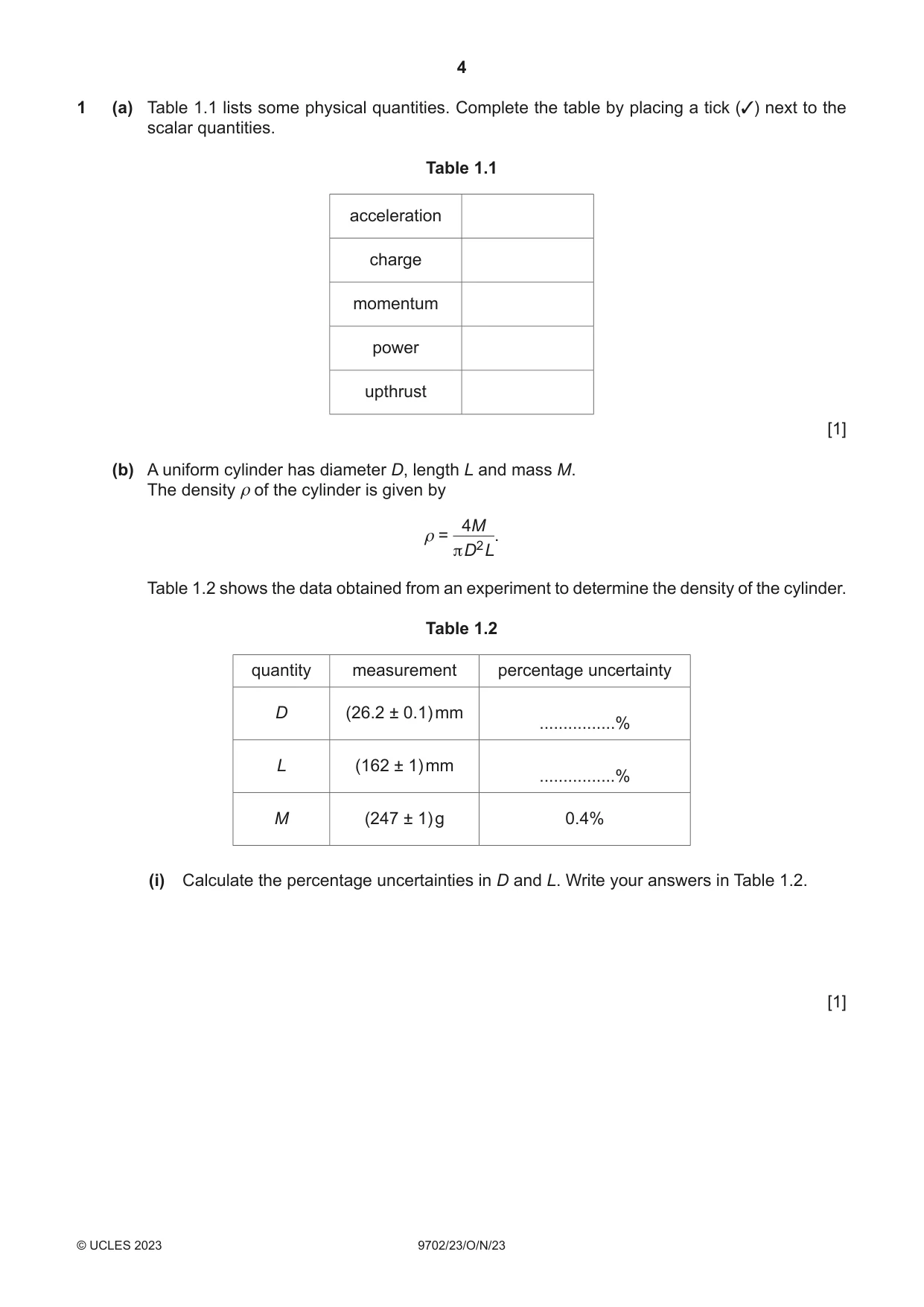
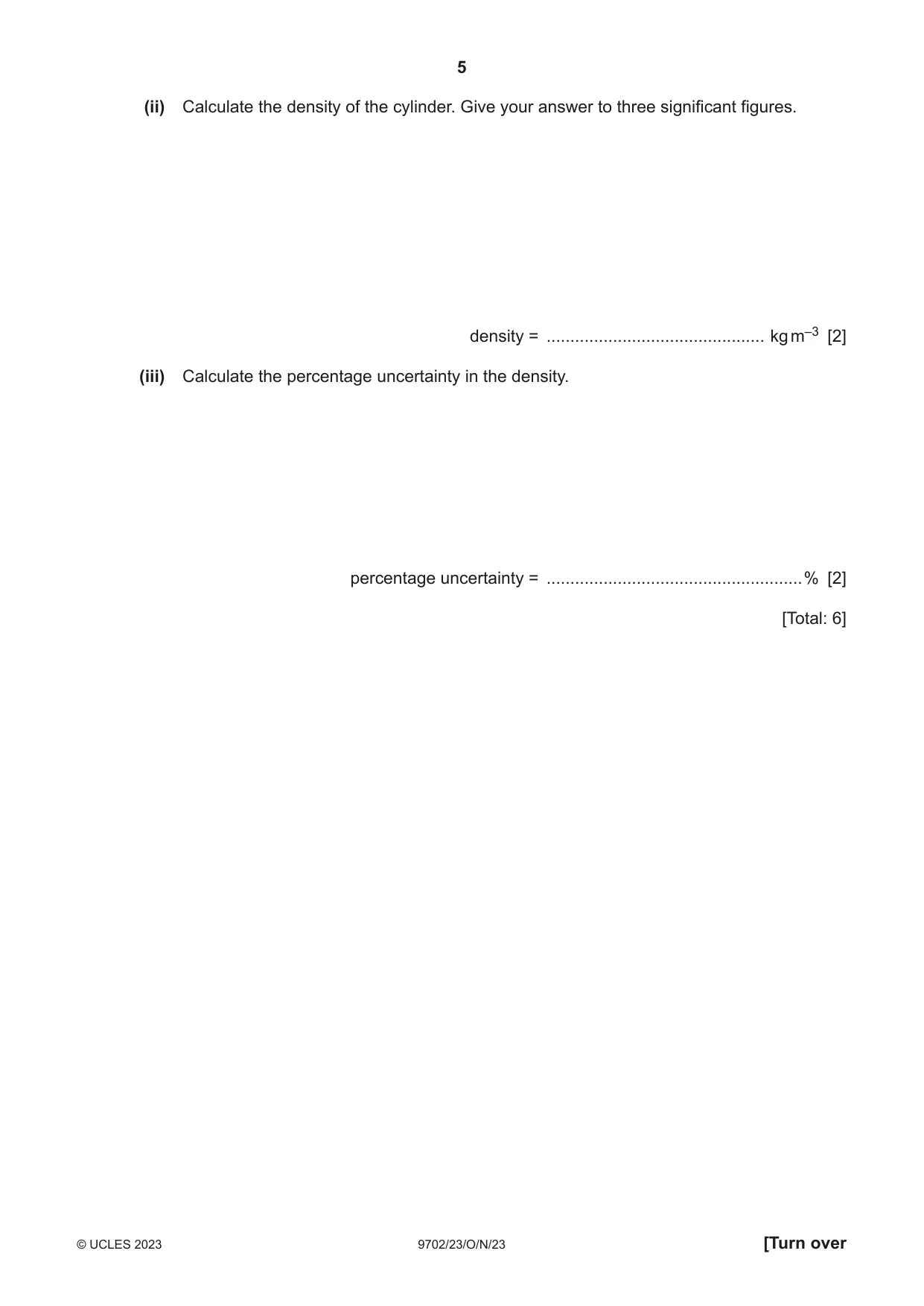
1 (a) Table 1.1 lists some physical quantities. Complete the table by placing a tick (✓) next to the scalar quantities. Table 1.1 acceleration charge momentum power upthrust [1] (b) A uniform cylinder has diameter D, length L and mass M. The density ρ of the cylinder is given by 4M ρ = . π D2 L Table 1.2 shows the data obtained from an experiment to determine the density of the cylinder. Table 1.2 quantity measurement percentage uncertainty D (26.2 ± 0.1) mm ................% L (162 ± 1) mm ................% M (247 ± 1) g 0.4% (i) Calculate the percentage uncertainties in D and L. Write your answers in Table 1.2. [1] (ii) Calculate the density of the cylinder. Give your answer to three significant figures. density = .............................................. kg m–3 [2] (iii) Calculate the percentage uncertainty in the density. percentage uncertainty = ......................................................% [2] [Total: 6]
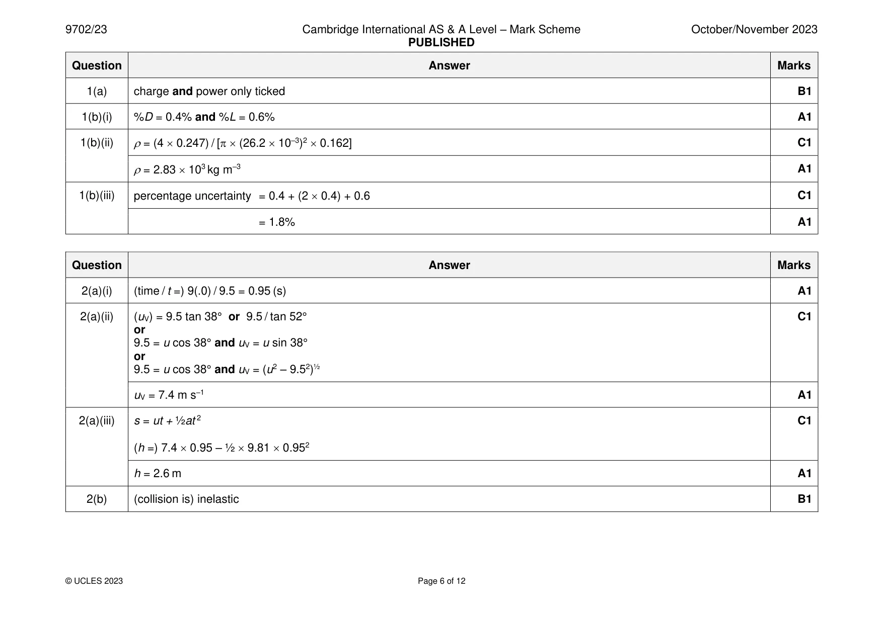
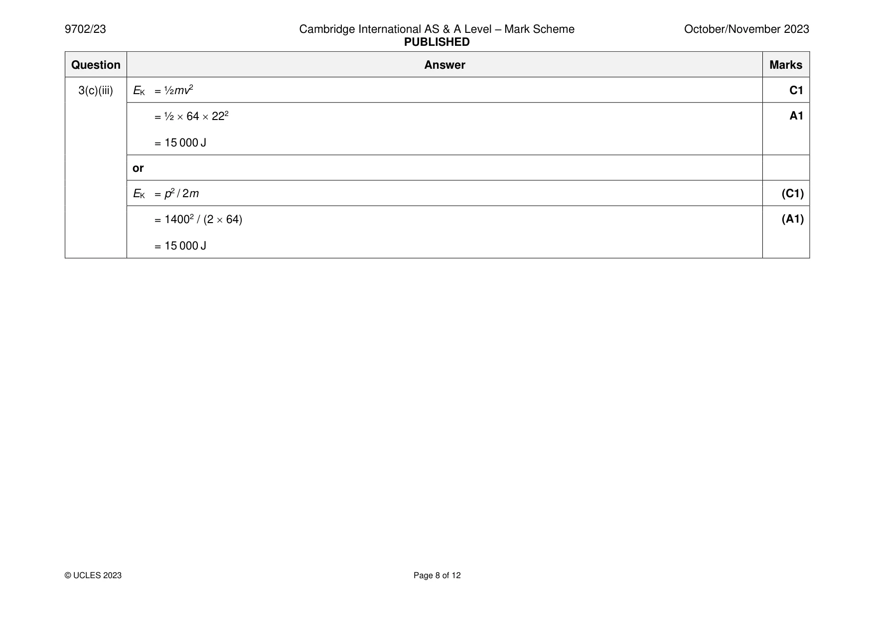
Mark scheme: Question Answer Marks 1(a) charge and power only ticked B1 1(b)(i) %D = 0.4% and %L = 0.6% A1 1(b)(ii) = (4 0.247) / [ (26.2 10–3)2 0.162] C1 = 2.83 103 kg m–3 A1 1(b)(iii) percentage uncertainty = 0.4 + (2 0.4) + 0.6 C1 = 1.8% A1
Q2 · A ball on horizontal ground is kicked towards a vertical wall
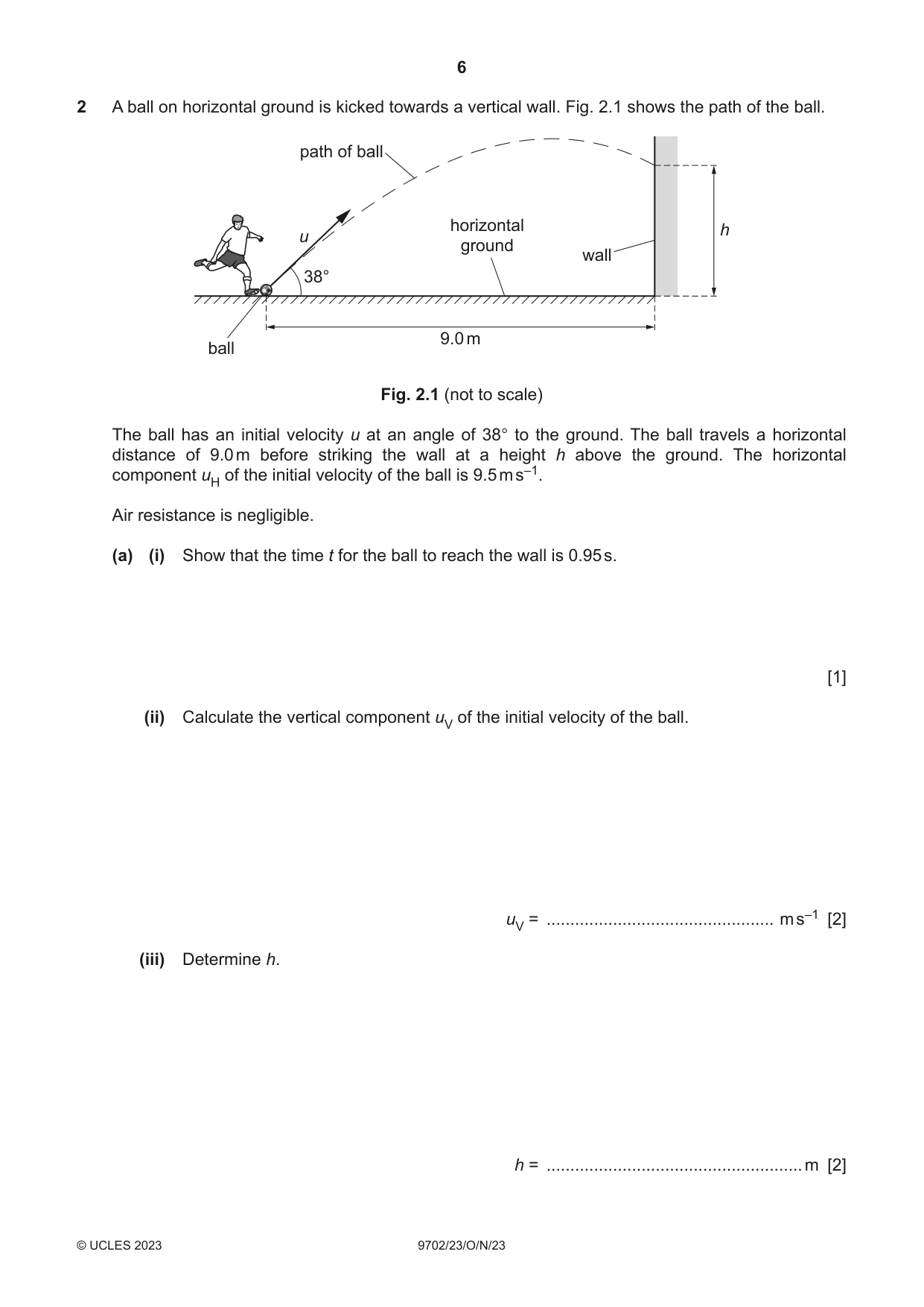
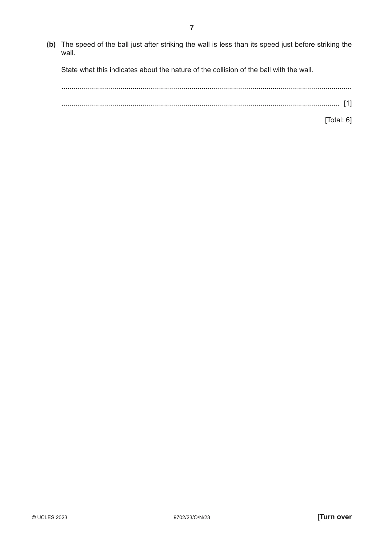
2 A ball on horizontal ground is kicked towards a vertical wall. Fig. 2.1 shows the path of the ball. path of ball horizontal h u ground wall 38° 9.0 m ball Fig. 2.1 (not to scale) The ball has an initial velocity u at an angle of 38° to the ground. The ball travels a horizontal distance of 9.0 m before striking the wall at a height h above the ground. The horizontal component uH of the initial velocity of the ball is 9.5 m s–1. Air resistance is negligible. (a) (i) Show that the time t for the ball to reach the wall is 0.95 s. [1] (ii) Calculate the vertical component uV of the initial velocity of the ball. uV = ................................................ m s–1 [2] (iii) Determine h. h = ...................................................... m [2] (b) The speed of the ball just after striking the wall is less than its speed just before striking the wall. State what this indicates about the nature of the collision of the ball with the wall. ................................................................................................................................................... ............................................................................................................................................. [1] [Total: 6]
Mark scheme: 2(a)(i) (time / t =) 9(.0) / 9.5 = 0.95 (s) A1 2(a)(ii) (uV) = 9.5 tan 38° or 9.5 / tan 52° C1 or 9.5 = u cos 38° and uV = u sin 38° or 9.5 = u cos 38° and uV = (u2 – 9.52)½ uV = 7.4 m s–1 A1 2(a)(iii) s = ut + ½at 2 C1 (h =) 7.4 0.95 – ½ 9.81 0.952 h = 2.6 m A1 2(b) (collision is) inelastic B1
Q3 · State the conditions for a system to be in equilibrium
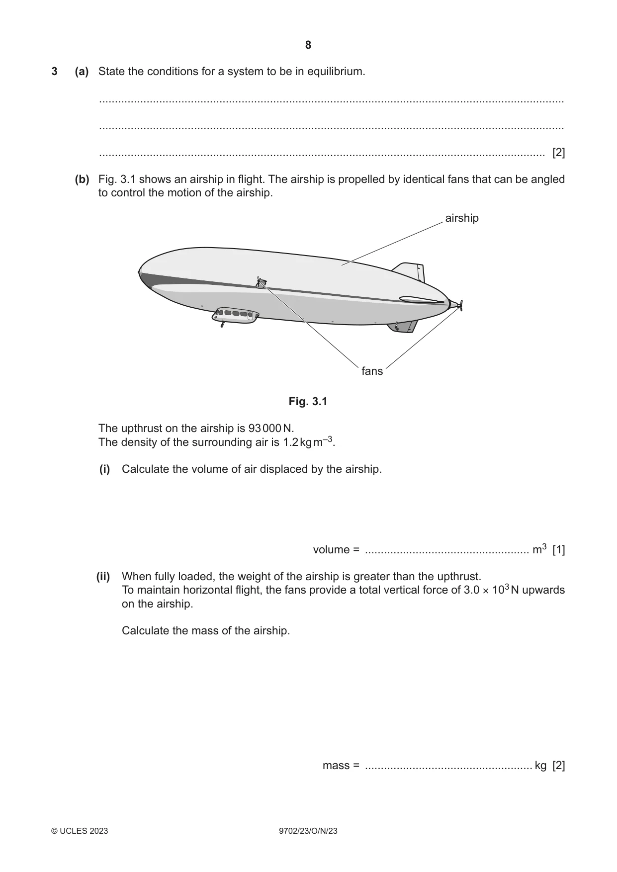
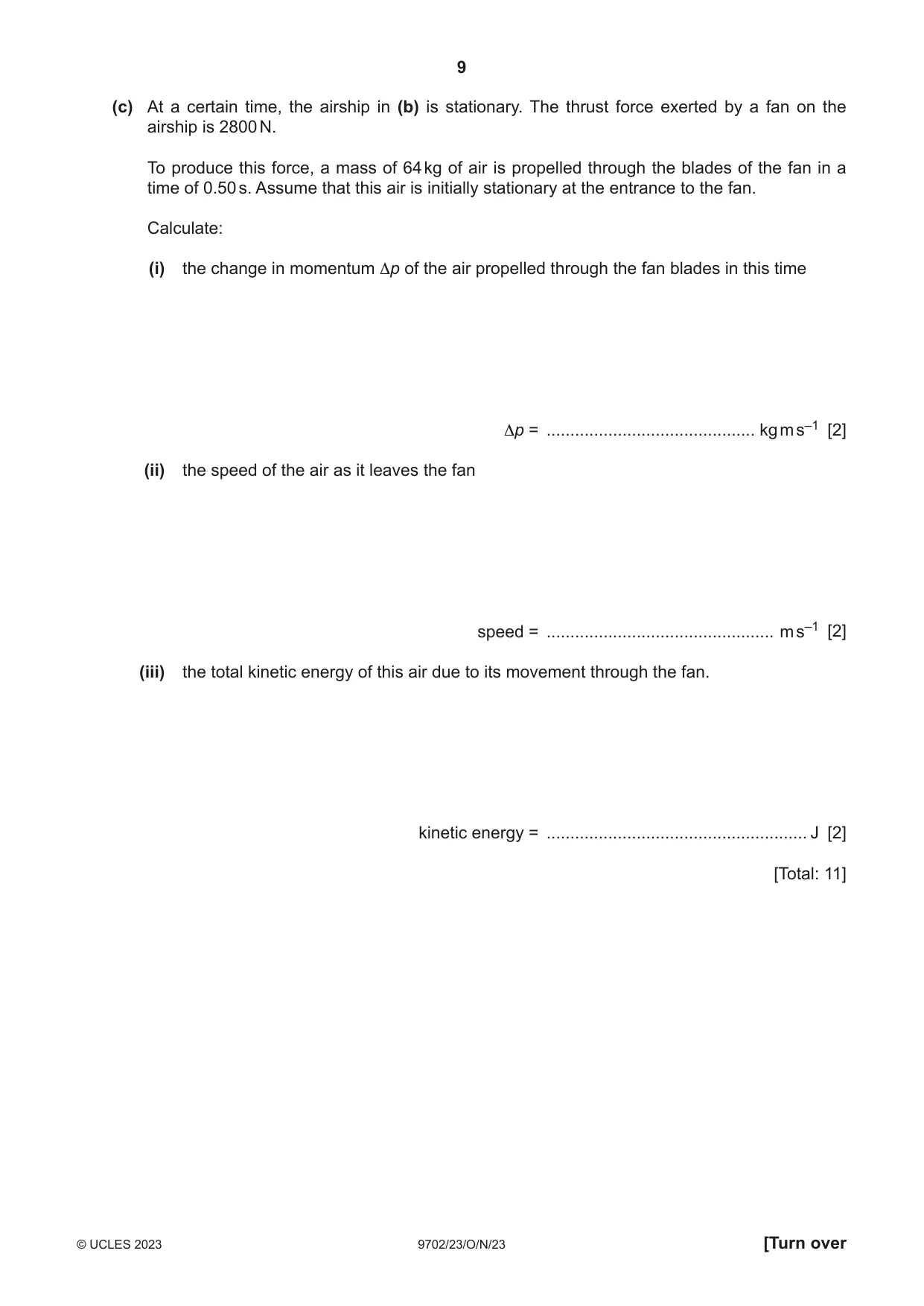
3 (a) State the conditions for a system to be in equilibrium. ................................................................................................................................................... ................................................................................................................................................... ............................................................................................................................................. [2] (b) Fig. 3.1 shows an airship in flight. The airship is propelled by identical fans that can be angled to control the motion of the airship. airship fans Fig. 3.1 The upthrust on the airship is 93 000 N. The density of the surrounding air is 1.2 kg m–3. (i) Calculate the volume of air displaced by the airship. volume = .................................................... m3 [1] (ii) When fully loaded, the weight of the airship is greater than the upthrust. To maintain horizontal flight, the fans provide a total vertical force of 3.0 × 10³ N upwards on the airship. Calculate the mass of the airship. mass = ..................................................... kg [2] (c) At a certain time, the airship in (b) is stationary. The thrust force exerted by a fan on the airship is 2800 N. To produce this force, a mass of 64 kg of air is propelled through the blades of the fan in a time of 0.50 s. Assume that this air is initially stationary at the entrance to the fan. Calculate: (i) the change in momentum ∆p of the air propelled through the fan blades in this time ∆p = ............................................ kg m s–1 [2] (ii) the speed of the air as it leaves the fan speed = ................................................ m s–1 [2] (iii) the total kinetic energy of this air due to its movement through the fan. kinetic energy = ....................................................... J [2] [Total: 11]
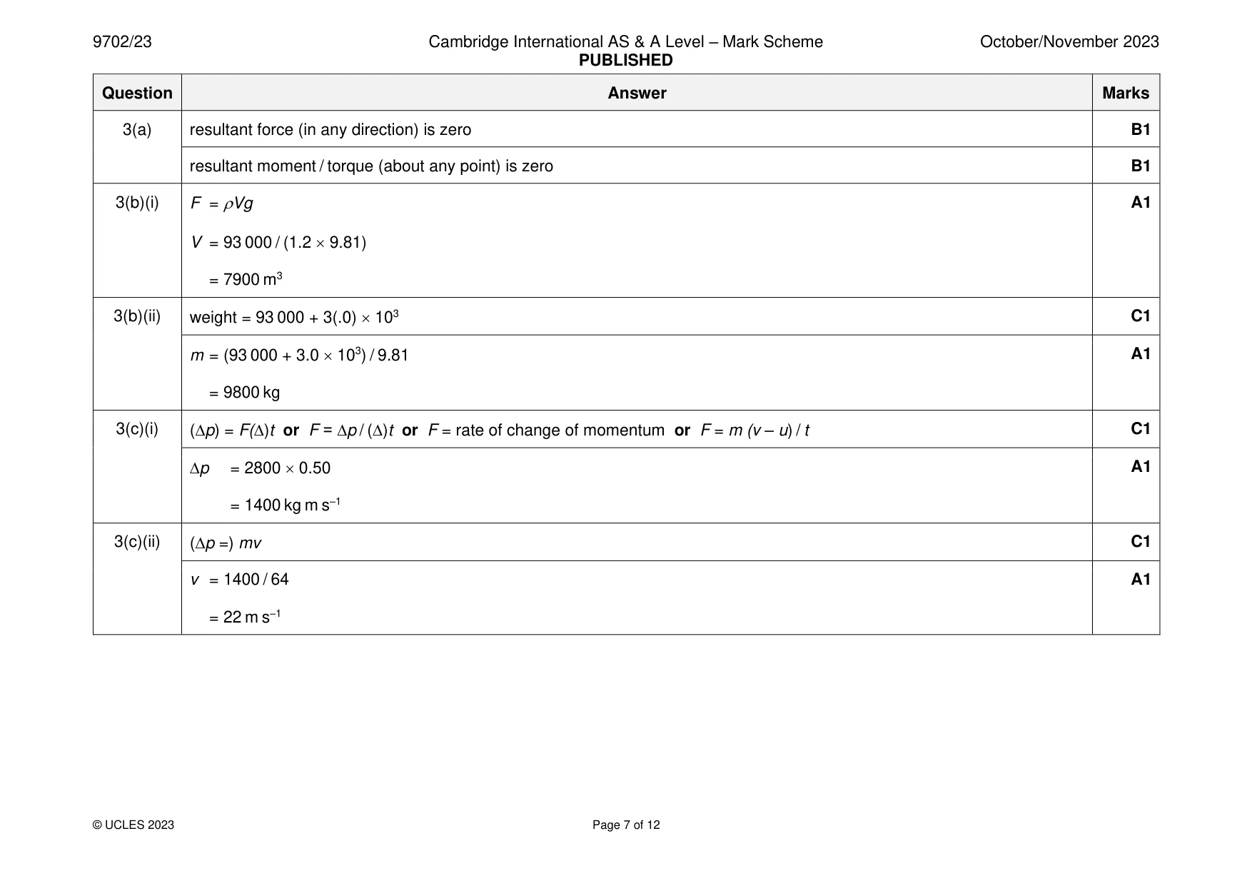
Mark scheme: 3(a) resultant force (in any direction) is zero B1 resultant moment / torque (about any point) is zero B1 3(b)(i) F = Vg A1 V = 93 000 / (1.2 9.81) = 7900 m3 3(b)(ii) weight = 93 000 + 3(.0) 103 C1 m = (93 000 + 3.0 103) / 9.81 A1 = 9800 kg 3(c)(i) (p) = F()t or F = ∆p / ()t or F = rate of change of momentum or F = m (v – u) / t C1 ∆p = 2800 0.50 A1 = 1400 kg m s–1 3(c)(ii) (p =) mv C1 v = 1400 / 64 A1 = 22 m s–1 3(c)(iii) EK = ½mv2 C1 = ½ 64 222 A1 = 15 000 J or EK = p2 / 2m (C1) = 14002 / (2 64) (A1) = 15 000 J
Q4 · The variation with extension x of the tensile force F for two wires, G and H, made from…
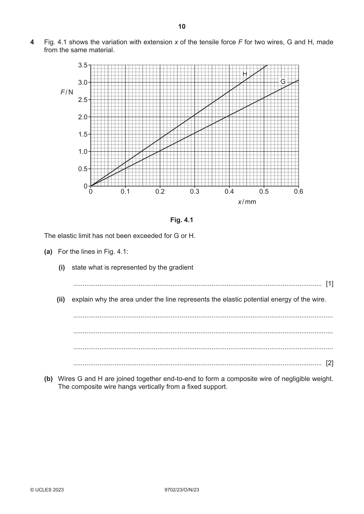
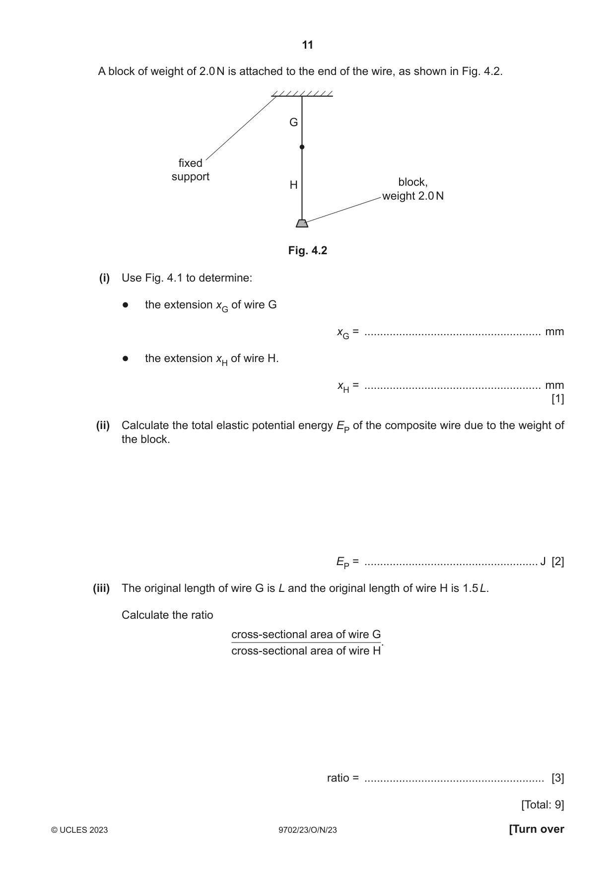
4 Fig. 4.1 shows the variation with extension x of the tensile force F for two wires, G and H, made from the same material. 3.5 H 3.0 G F / N 2.5 2.0 1.5 1.0 0.5 0 0 0.1 0.2 0.3 0.4 0.5 0.6 x / mm Fig. 4.1 The elastic limit has not been exceeded for G or H. (a) For the lines in Fig. 4.1: (i) state what is represented by the gradient ..................................................................................................................................... [1] (ii) explain why the area under the line represents the elastic potential energy of the wire. ........................................................................................................................................... ........................................................................................................................................... ........................................................................................................................................... ..................................................................................................................................... [2] (b) Wires G and H are joined together end‑to‑end to form a composite wire of negligible weight. The composite wire hangs vertically from a fixed support. A block of weight of 2.0 N is attached to the end of the wire, as shown in Fig. 4.2. G fixed support H block, weight 2.0 N Fig. 4.2 (i) Use Fig. 4.1 to determine: ● the extension xG of wire G xG = ........................................................ mm ● the extension xH of wire H. xH = ........................................................ mm [1] (ii) Calculate the total elastic potential energy EP of the composite wire due to the weight of the block. EP = ....................................................... J [2] (iii) The original length of wire G is L and the original length of wire H is 1.5 L. Calculate the ratio cross‑sectional area of wire G cross‑sectional area of wire H. ratio = ......................................................... [3] [Total: 9]
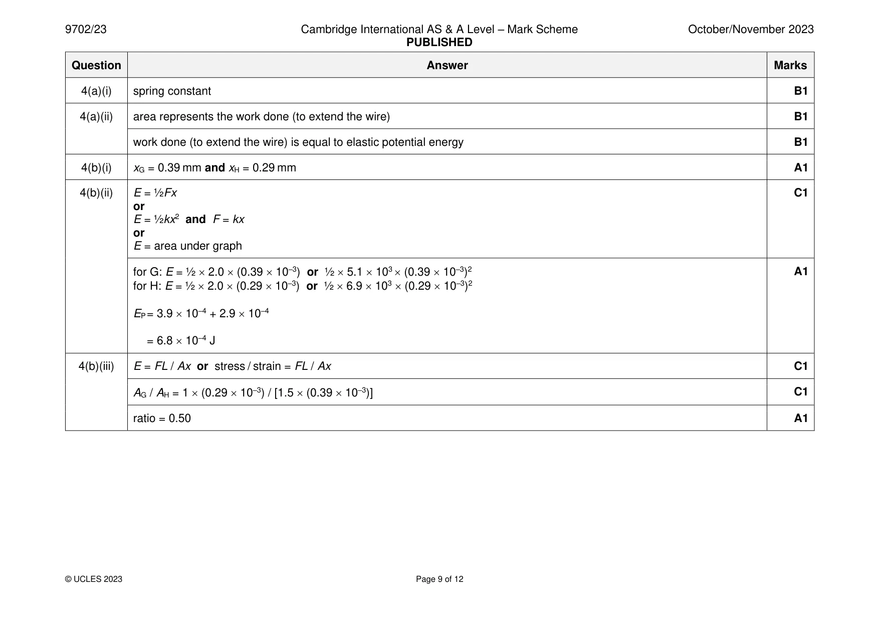
Mark scheme: 4(a)(i) spring constant B1 4(a)(ii) area represents the work done (to extend the wire) B1 work done (to extend the wire) is equal to elastic potential energy B1 4(b)(i) xG = 0.39 mm and xH = 0.29 mm A1 4(b)(ii) E = ½Fx C1 or E = ½kx2 and F = kx or E = area under graph for G: E = ½ 2.0 (0.39 10–3) or ½ 5.1 103 (0.39 10–3)2 A1 for H: E = ½ 2.0 (0.29 10–3) or ½ 6.9 103 (0.29 10–3)2 EP = 3.9 10–4 + 2.9 10–4 = 6.8 10–4 J 4(b)(iii) E = FL / Ax or stress / strain = FL / Ax C1 AG / AH = 1 (0.29 10–3) / [1.5 (0.39 10–3)] C1 ratio = 0.50 A1
Q5 · Two point sources, A and B, produce coherent electromagnetic waves
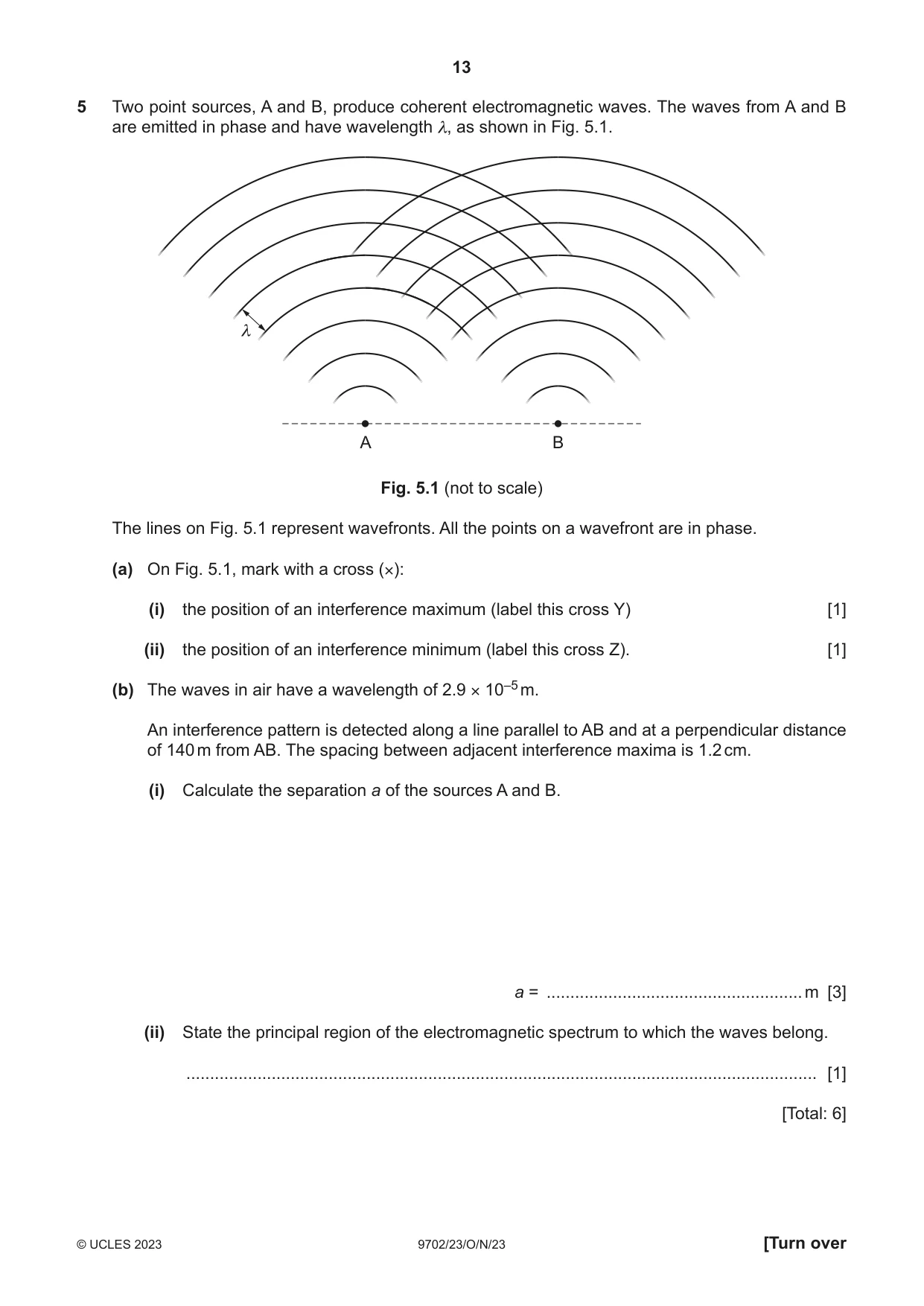
5 Two point sources, A and B, produce coherent electromagnetic waves. The waves from A and B are emitted in phase and have wavelength λ, as shown in Fig. 5.1. λ A B Fig. 5.1 (not to scale) The lines on Fig. 5.1 represent wavefronts. All the points on a wavefront are in phase. (a) On Fig. 5.1, mark with a cross (×): (i) the position of an interference maximum (label this cross Y) [1] (ii) the position of an interference minimum (label this cross Z). [1] (b) The waves in air have a wavelength of 2.9 × 10⁻⁵ m. An interference pattern is detected along a line parallel to AB and at a perpendicular distance of 140 m from AB. The spacing between adjacent interference maxima is 1.2 cm. (i) Calculate the separation a of the sources A and B. a = ...................................................... m [3] (ii) State the principal region of the electromagnetic spectrum to which the waves belong. ..................................................................................................................................... [1] [Total: 6]
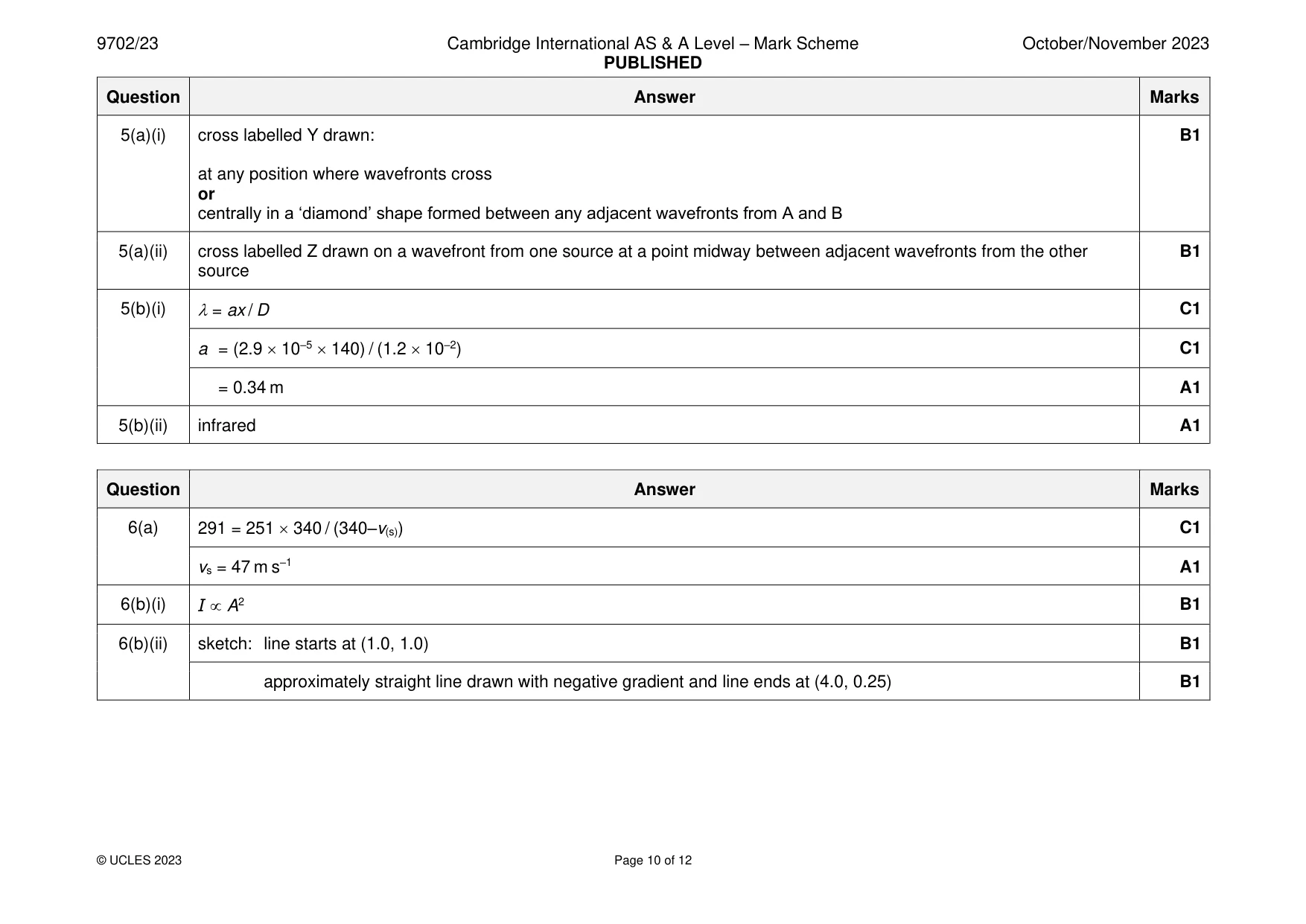
Mark scheme: 5(a)(i) cross labelled Y drawn: B1 at any position where wavefronts cross or centrally in a ‘diamond’ shape formed between any adjacent wavefronts from A and B 5(a)(ii) cross labelled Z drawn on a wavefront from one source at a point midway between adjacent wavefronts from the other B1 source 5(b)(i) = ax / D C1 a = (2.9 10–5 140) / (1.2 10–2) C1 = 0.34 m A1 5(b)(ii) infrared A1
Q6 · A train travels at constant speed along a straight horizontal track towards an observer…
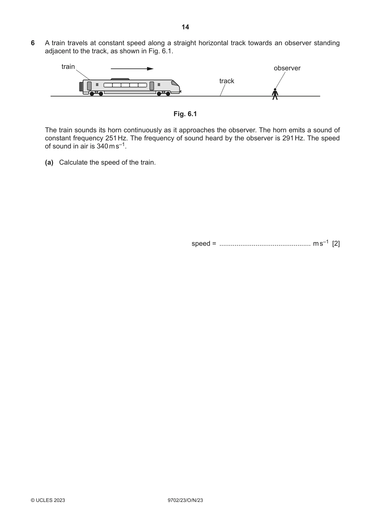
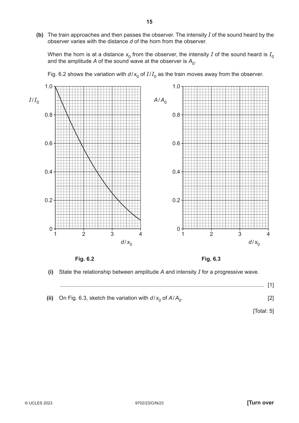
6 A train travels at constant speed along a straight horizontal track towards an observer standing adjacent to the track, as shown in Fig. 6.1. train observer track Fig. 6.1 The train sounds its horn continuously as it approaches the observer. The horn emits a sound of constant frequency 251 Hz. The frequency of sound heard by the observer is 291 Hz. The speed of sound in air is 340 m s–1. (a) Calculate the speed of the train. speed = ................................................ m s–1 [2] (b) The train approaches and then passes the observer. The intensity I of the sound heard by the observer varies with the distance d of the horn from the observer. When the horn is at a distance x0 from the observer, the intensity I of the sound heard is I0 and the amplitude A of the sound wave at the observer is A0. Fig. 6.2 shows the variation with d / x0 of I / I0 as the train moves away from the observer. 1.0 1.0 I / I0 A / A0 0.8 0.8 0.6 0.6 0.4 0.4 0.2 0.2 0 0 1 2 3 4 1 2 3 4 d / x0 d / x0 Fig. 6.2 Fig. 6.3 (i) State the relationship between amplitude A and intensity I for a progressive wave. ..................................................................................................................................... [1] (ii) On Fig. 6.3, sketch the variation with d / x0 of A / A0. [2] [Total: 5]
Mark scheme: 6(a) 291 = 251 340 / (340–v(s)) C1 vs = 47 m s–1 A1 6(b)(i) I A2 B1 6(b)(ii) sketch: line starts at (1.0, 1.0) B1 approximately straight line drawn with negative gradient and line ends at (4.0, 0.25) B1
Question 7
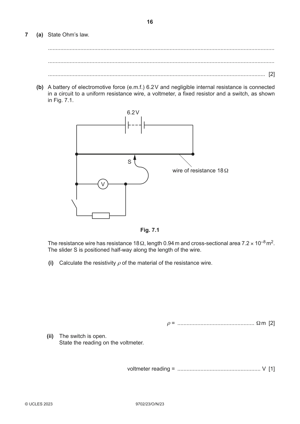
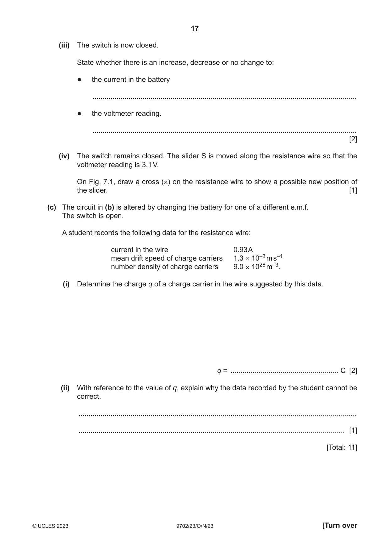
7 (a) State Ohm’s law. ................................................................................................................................................... ................................................................................................................................................... ............................................................................................................................................. [2] (b) A battery of electromotive force (e.m.f.) 6.2 V and negligible internal resistance is connected in a circuit to a uniform resistance wire, a voltmeter, a fixed resistor and a switch, as shown in Fig. 7.1. 6.2 V S wire of resistance 18 Ω V Fig. 7.1 The resistance wire has resistance 18 Ω, length 0.94 m and cross‑sectional area 7.2 × 10⁻⁸ m2. The slider S is positioned half‑way along the length of the wire. (i) Calculate the resistivity ρ of the material of the resistance wire. ρ = .................................................. Ω m [2] (ii) The switch is open. State the reading on the voltmeter. voltmeter reading = ...................................................... V [1] (iii) The switch is now closed. State whether there is an increase, decrease or no change to: ● the current in the battery .................................................................................................................................... ● the voltmeter reading. .................................................................................................................................... [2] (iv) The switch remains closed. The slider S is moved along the resistance wire so that the voltmeter reading is 3.1 V. On Fig. 7.1, draw a cross (×) on the resistance wire to show a possible new position of the slider. [1] (c) The circuit in (b) is altered by changing the battery for one of a different e.m.f. The switch is open. A student records the following data for the resistance wire: current in the wire 0.93 A mean drift speed of charge carriers 1.3 × 10⁻³ m s–1 number density of charge carriers 9.0 × 1028 m–3. (i) Determine the charge q of a charge carrier in the wire suggested by this data. q = ...................................................... C [2] (ii) With reference to the value of q, explain why the data recorded by the student cannot be correct. ........................................................................................................................................... ..................................................................................................................................... [1] [Total: 11]
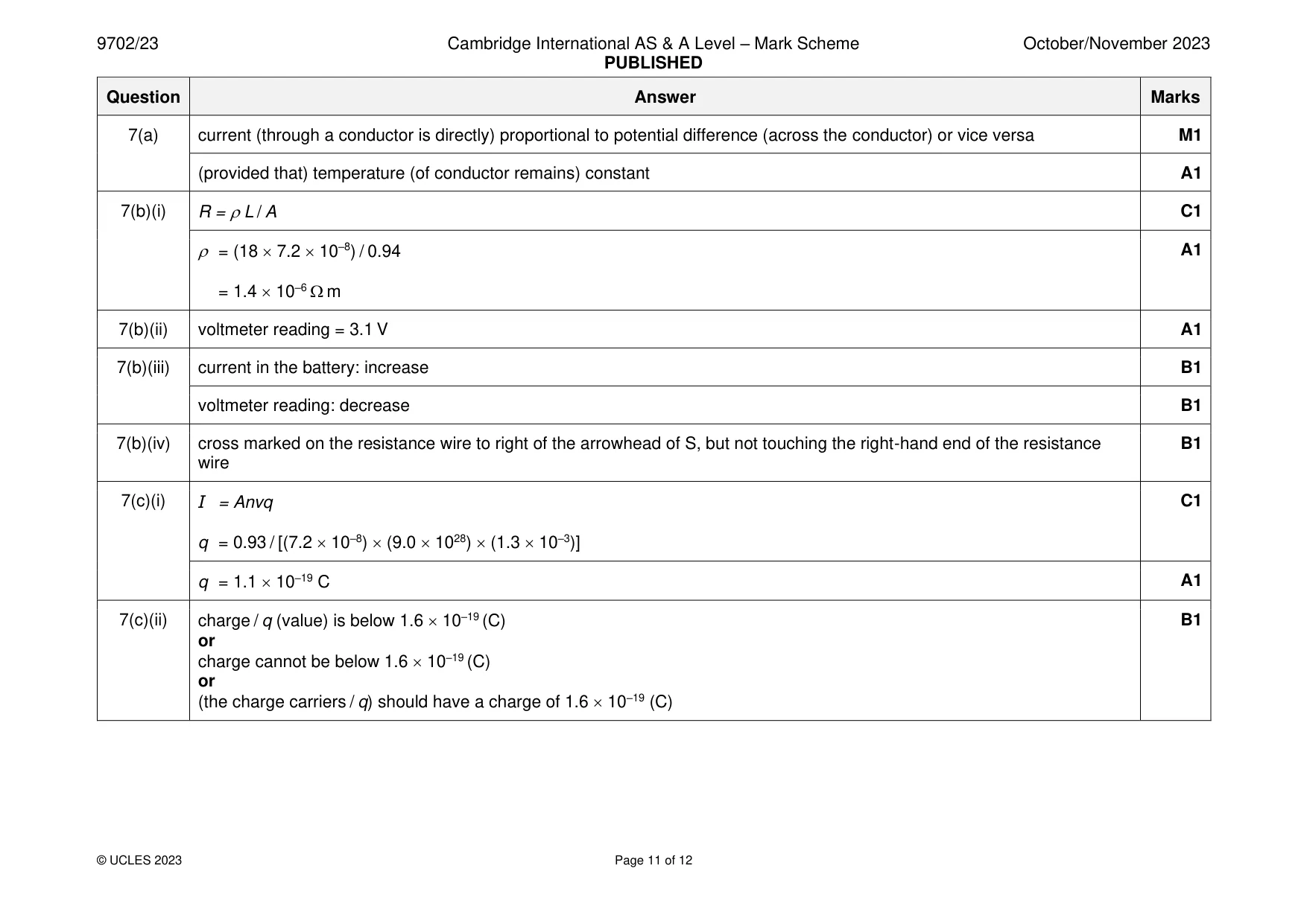
Mark scheme: 7(a) current (through a conductor is directly) proportional to potential difference (across the conductor) or vice versa M1 (provided that) temperature (of conductor remains) constant A1 7(b)(i) R = L / A C1 = (18 7.2 10–8) / 0.94 A1 = 1.4 10–6 m 7(b)(ii) voltmeter reading = 3.1 V A1 7(b)(iii) current in the battery: increase B1 voltmeter reading: decrease B1 7(b)(iv) cross marked on the resistance wire to right of the arrowhead of S, but not touching the right-hand end of the resistance B1 wire 7(c)(i) I = Anvq C1 q = 0.93 / [(7.2 10–8) (9.0 1028) (1.3 10–3)] q = 1.1 10–19 C A1 7(c)(ii) charge / q (value) is below 1.6 10–19 (C) B1 or charge cannot be below 1.6 10–19 (C) or (the charge carriers / q) should have a charge of 1.6 10–19 (C)
Q8 · The nuclide 2312Mg is an isotope of magnesium that undergoes β+ decay to form a new…
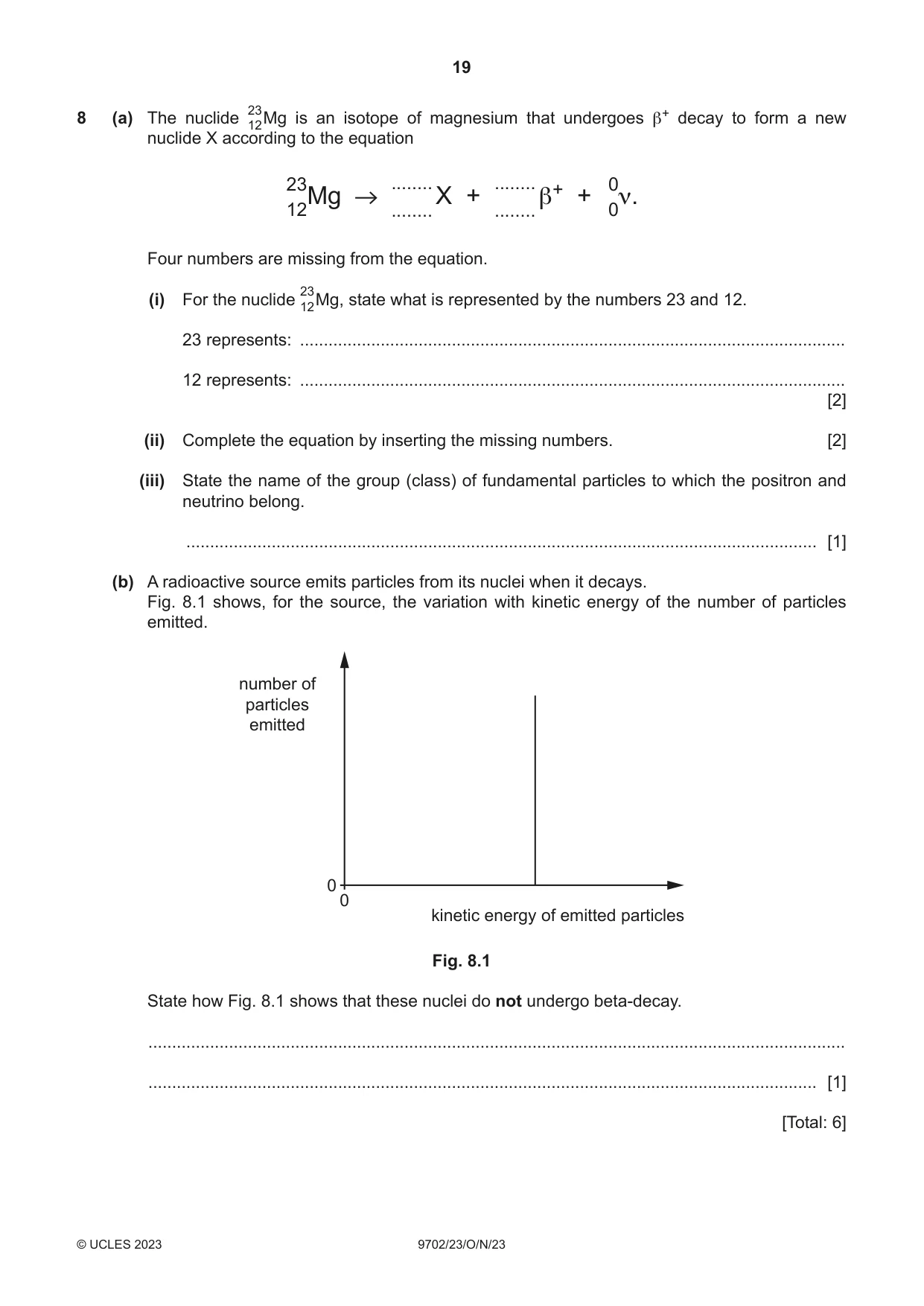
8 (a) The nuclide 2312Mg is an isotope of magnesium that undergoes β+ decay to form a new nuclide X according to the equation 23 ........ ........ 0 12Mg ........ X + ........ β+ + 0ν. Four numbers are missing from the equation. (i) For the nuclide 2312Mg, state what is represented by the numbers 23 and 12. 23 represents: ................................................................................................................... 12 represents: ................................................................................................................... [2] (ii) Complete the equation by inserting the missing numbers. [2] (iii) State the name of the group (class) of fundamental particles to which the positron and neutrino belong. ..................................................................................................................................... [1] (b) A radioactive source emits particles from its nuclei when it decays. Fig. 8.1 shows, for the source, the variation with kinetic energy of the number of particles emitted. number of particles emitted 0 0 kinetic energy of emitted particles Fig. 8.1 State how Fig. 8.1 shows that these nuclei do not undergo beta‑decay. ................................................................................................................................................... ............................................................................................................................................. [1] [Total: 6]
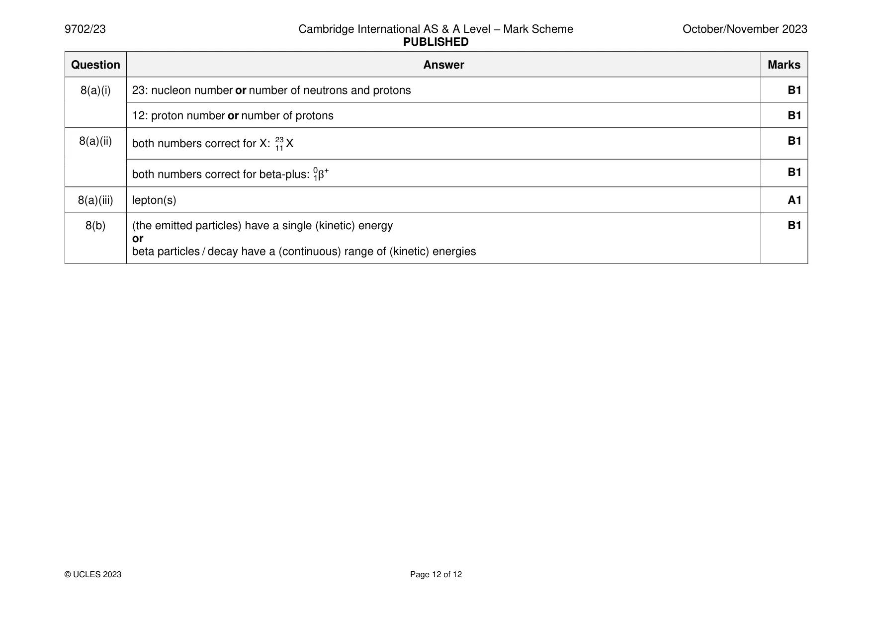
Mark scheme: 8(a)(i) 23: nucleon number or number of neutrons and protons B1 12: proton number or number of protons B1 8(a)(ii) both numbers correct for X: 2311 X B1 both numbers correct for beta-plus: 01β+ B1 8(a)(iii) lepton(s) A1 8(b) (the emitted particles) have a single (kinetic) energy B1 or beta particles / decay have a (continuous) range of (kinetic) energies
What was in this paper
The subtopics covered by these 8 questions, and how many questions each got. Open one in a new tab to see every Cambridge question on it.
What you needed in this session
Cambridge’s own grade thresholds for 2023 Oct/Nov, Paper 2 · Variant 3. A higher threshold means an easier paper — the bar moves with how the cohort did.