Cambridge IGCSE Physics (9-1) 0972 — 2020 May/June Paper 4 · Variant 1
0972/41/M/J/20 · 10 questions · 80 marks · ≈90 min
The question paper and its mark scheme, free to read here and free to download. This is Cambridge’s own paper, exactly as it was sat.
Question paper16 pages

Mark scheme10 pages
Answers below. Sit the paper first if you are practising.

Questions as text
Q1 · An aeroplane of mass 2.5 × 10⁵ kg lands with a speed of 62 m / s, on a horizontal runway…
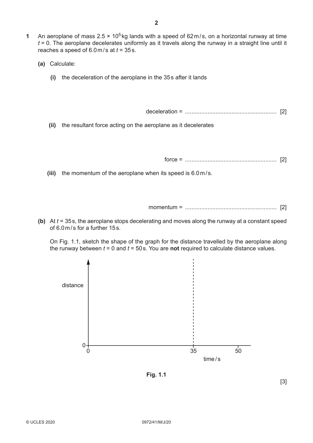
1 An aeroplane of mass 2.5 × 10⁵ kg lands with a speed of 62 m / s, on a horizontal runway at time t = 0. The aeroplane decelerates uniformly as it travels along the runway in a straight line until it reaches a speed of 6.0 m / s at t = 35 s. (a) Calculate: (i) the deceleration of the aeroplane in the 35 s after it lands deceleration = ......................................................... [2] (ii) the resultant force acting on the aeroplane as it decelerates force = ......................................................... [2] (iii) the momentum of the aeroplane when its speed is 6.0 m / s. momentum = ......................................................... [2] (b) At t = 35 s, the aeroplane stops decelerating and moves along the runway at a constant speed of 6.0 m / s for a further 15 s. On Fig. 1.1, sketch the shape of the graph for the distance travelled by the aeroplane along the runway between t = 0 and t = 50 s. You are not required to calculate distance values. distance 0 0 35 50 time / s Fig. 1.1 [3] (c) As the aeroplane decelerates, its kinetic energy decreases. Suggest what happens to this energy. ................................................................................................................................................... ............................................................................................................................................. [1] [Total: 10]
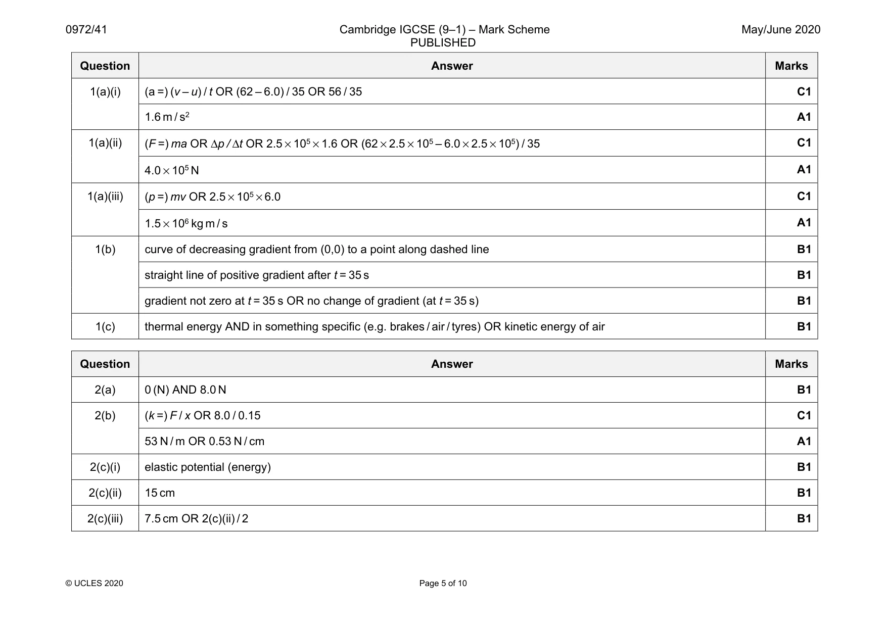
Mark scheme: 1(a)(i) (a =) (v – u) / t OR (62 – 6.0) / 35 OR 56 / 35 C1 1.6 m / s2 A1 1(a)(ii) (F =) ma OR Δp / Δt OR 2.5 × 105 × 1.6 OR (62 × 2.5 × 105 – 6.0 × 2.5 × 105) / 35 C1 4.0 × 10⁵ N A1 1(a)(iii) (p =) mv OR 2.5 × 105 × 6.0 C1 1.5 × 10⁶ kg m / s A1 1(b) curve of decreasing gradient from (0,0) to a point along dashed line B1 straight line of positive gradient after t = 35 s B1 gradient not zero at t = 35 s OR no change of gradient (at t = 35 s) B1 1(c) thermal energy AND in something specific (e.g. brakes / air / tyres) OR kinetic energy of air B1
Q2 · The extension–load graph for a light spring S
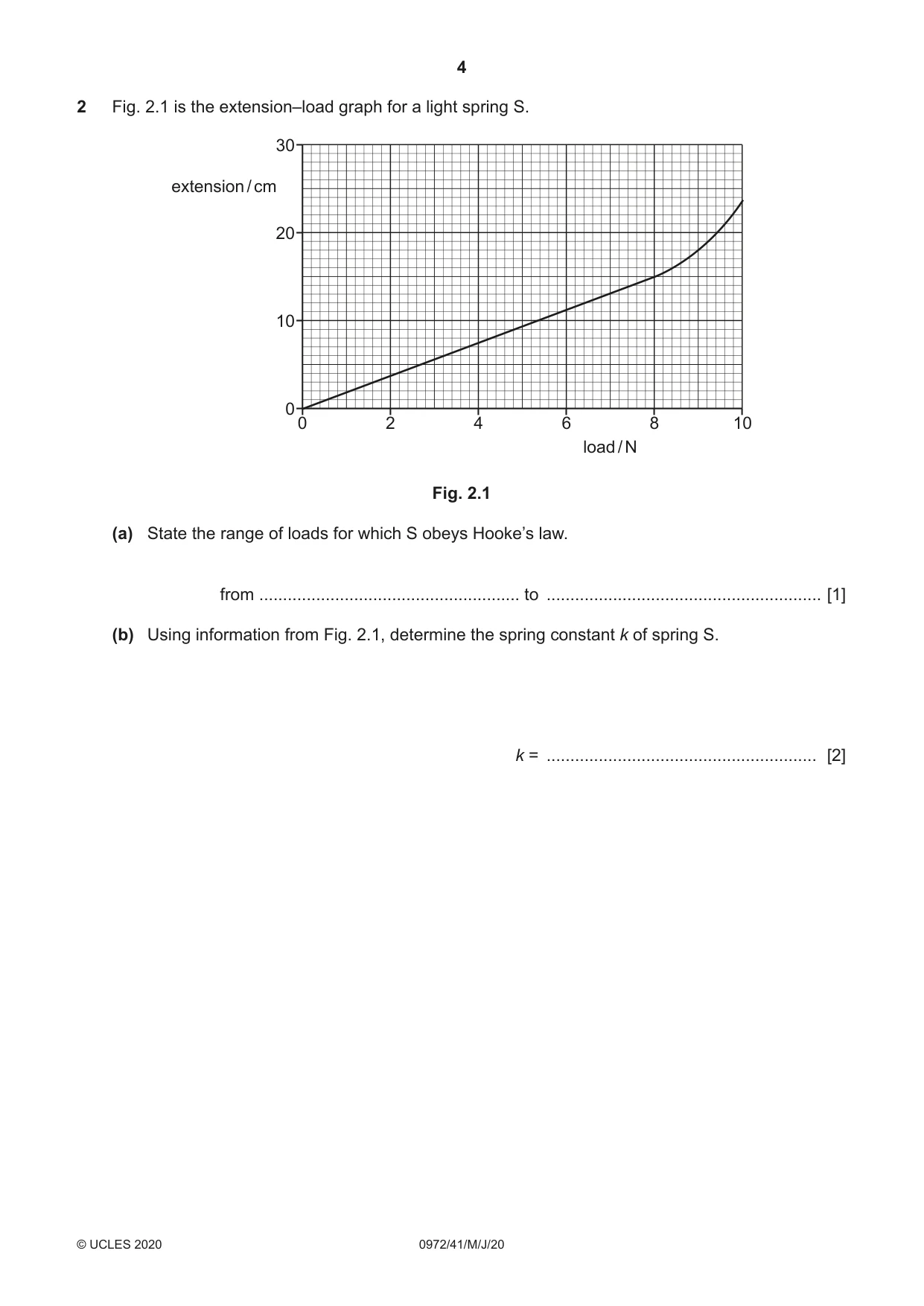
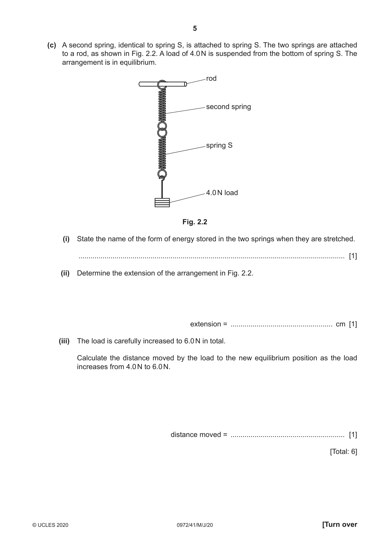
2 Fig. 2.1 is the extension–load graph for a light spring S. 30 extension / cm 20 10 0 0 2 4 6 8 10 load / N Fig. 2.1 (a) State the range of loads for which S obeys Hooke’s law. from ....................................................... to .......................................................... [1] (b) Using information from Fig. 2.1, determine the spring constant k of spring S. k = ......................................................... [2] (c) A second spring, identical to spring S, is attached to spring S. The two springs are attached to a rod, as shown in Fig. 2.2. A load of 4.0 N is suspended from the bottom of spring S. The arrangement is in equilibrium. rod second spring spring S 4.0 N load Fig. 2.2 (i) State the name of the form of energy stored in the two springs when they are stretched. ..................................................................................................................................... [1] (ii) Determine the extension of the arrangement in Fig. 2.2. extension = ................................................... cm [1] (iii) The load is carefully increased to 6.0 N in total. Calculate the distance moved by the load to the new equilibrium position as the load increases from 4.0 N to 6.0 N. distance moved = ......................................................... [1] [Total: 6]
Mark scheme: 2(a) 0 (N) AND 8.0 N B1 2(b) (k =) F / x OR 8.0 / 0.15 C1 53 N / m OR 0.53 N / cm A1 2(c)(i) elastic potential (energy) B1 2(c)(ii) 15 cm B1 2(c)(iii) 7.5 cm OR 2(c)(ii) / 2 B1
Q3 · Gas trapped in the sealed end of a tube by a dense liquid
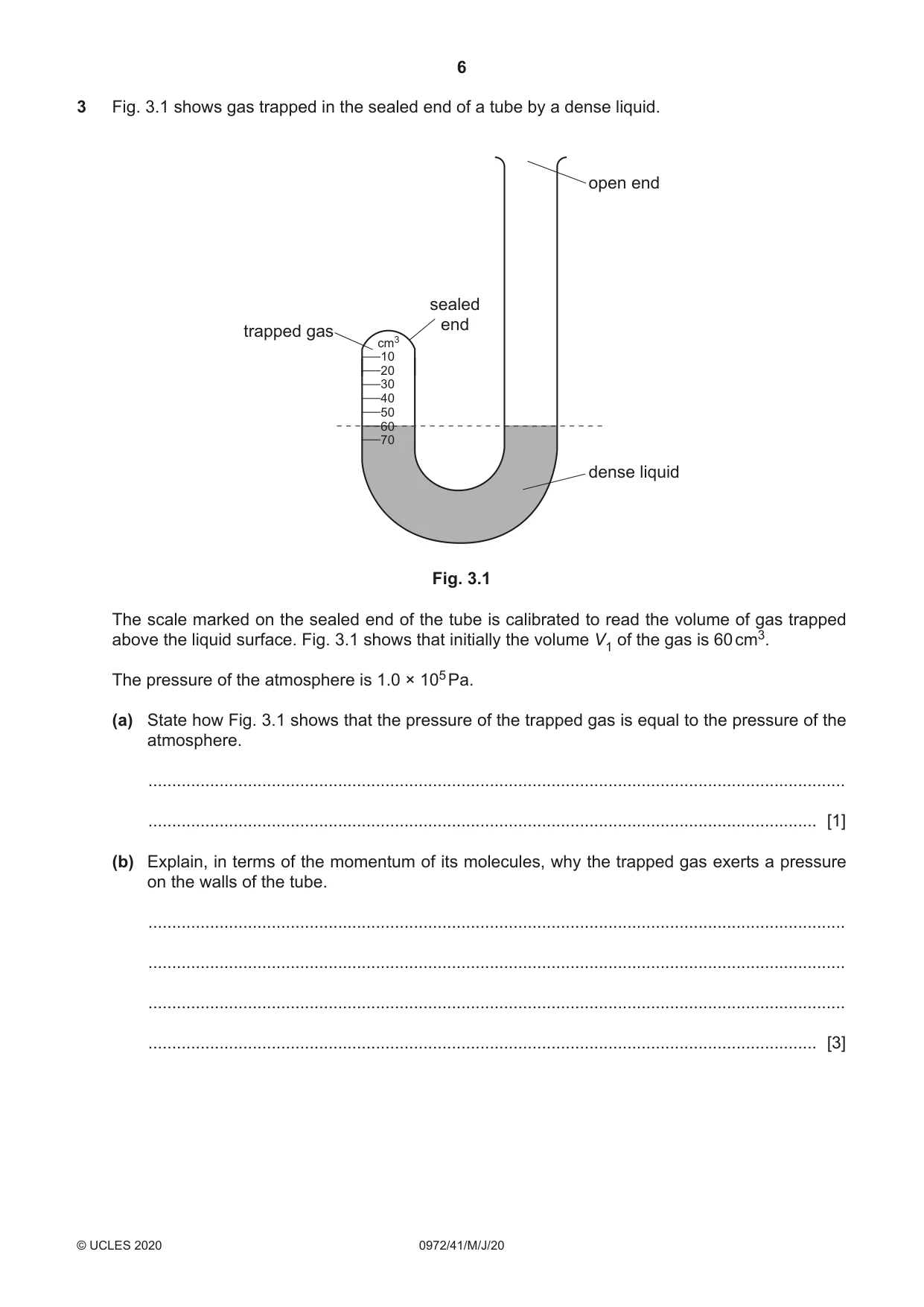
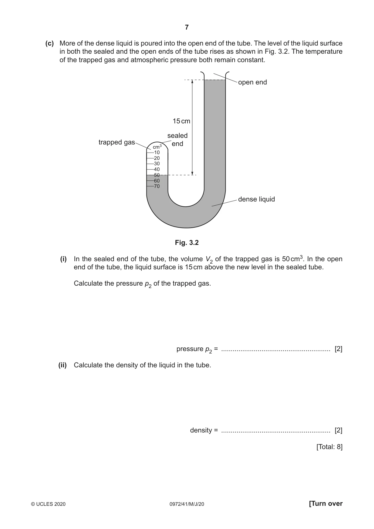
3 Fig. 3.1 shows gas trapped in the sealed end of a tube by a dense liquid. open end sealed end trapped gas cm3 10 20 30 40 50 60 70 dense liquid Fig. 3.1 The scale marked on the sealed end of the tube is calibrated to read the volume of gas trapped above the liquid surface. Fig. 3.1 shows that initially the volume V1 of the gas is 60 cm3. The pressure of the atmosphere is 1.0 × 10⁵ Pa. (a) State how Fig. 3.1 shows that the pressure of the trapped gas is equal to the pressure of the atmosphere. ................................................................................................................................................... ............................................................................................................................................. [1] (b) Explain, in terms of the momentum of its molecules, why the trapped gas exerts a pressure on the walls of the tube. ................................................................................................................................................... ................................................................................................................................................... ................................................................................................................................................... ............................................................................................................................................. [3] (c) More of the dense liquid is poured into the open end of the tube. The level of the liquid surface in both the sealed and the open ends of the tube rises as shown in Fig. 3.2. The temperature of the trapped gas and atmospheric pressure both remain constant. open end 15 cm sealed trapped gas end cm3 10 20 30 40 50 60 70 dense liquid Fig. 3.2 (i) In the sealed end of the tube, the volume V2 of the trapped gas is 50 cm3. In the open end of the tube, the liquid surface is 15 cm above the new level in the sealed tube. Calculate the pressure p2 of the trapped gas. pressure p2 = ......................................................... [2] (ii) Calculate the density of the liquid in the tube. density = ......................................................... [2] [Total: 8]
Mark scheme: 3(a) liquid levels in the two limbs of the tube are equal B1 3(b) molecules collide with the walls (of the container) B1 momentum of molecules changes (reverses) B1 this causes a force AND force spread out (over area of walls) B1 3(c)(i) (p2 =) p1V1 / V2 = 1.0 × 105 × 60 / 50 C1 1.2 × 10⁵ Pa A1 3(c)(ii) p2 = patm + hρg OR 1.2 × 10⁵ – 1.0 × 10⁵ OR 2.0 × 10⁴ OR (ρ =) 2.0 × 10⁴ / (0.15 × 10) C1 1.3 × 10⁴ kg m–3 A1
Q4 · Water has a specific heat capacity of 4200 J / (kg °C) and a boiling point of 100 °C
4 Water has a specific heat capacity of 4200 J / (kg °C) and a boiling point of 100 °C. (a) State what is meant by boiling point. ................................................................................................................................................... ............................................................................................................................................. [1] (b) A mass of 0.30 kg of water at its boiling point is poured into a copper container which is initially at 11 °C. After a few seconds, the temperature of the container and the water are both 95 °C. (i) Calculate the energy transferred from the water. energy transferred = ......................................................... [2] (ii) Calculate the thermal capacity of the copper container. thermal capacity of the copper container = ......................................................... [2] (iii) Water from the container evaporates and the temperature of the remaining water decreases slowly. Explain, in terms of molecules, why evaporation causes the temperature of the remaining water to decrease. ........................................................................................................................................... ........................................................................................................................................... ........................................................................................................................................... ..................................................................................................................................... [3] [Total: 8]
Mark scheme: 4(a) temperature at which liquid turns into gas B1 4(b)(i) (E =) mcΔT OR 0.30 × 4200 × (100 – 95) C1 6300 J A1 4(b)(ii) (C =) E / ΔT OR 6300 / 84 C1 75 J / °C A1 4(b)(iii) molecules do work against attractive force as they evaporate B1 more energetic molecules more likely to escape B1 average energy of remaining molecules decreases B1
Q5 · The distance between the centre of a thin converging lens and each principal focus is 5.0…
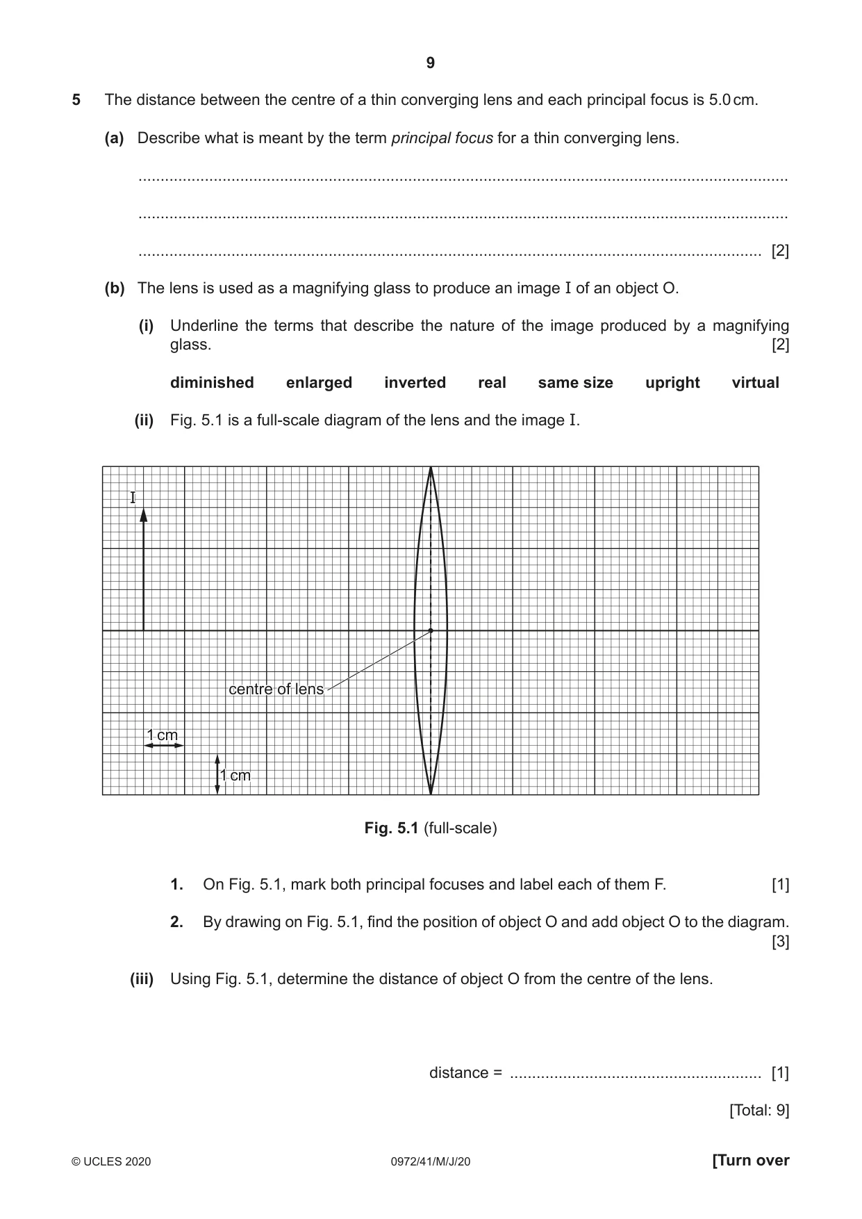
5 The distance between the centre of a thin converging lens and each principal focus is 5.0 cm. (a) Describe what is meant by the term principal focus for a thin converging lens. ................................................................................................................................................... ................................................................................................................................................... ............................................................................................................................................. [2] (b) The lens is used as a magnifying glass to produce an image I of an object O. (i) Underline the terms that describe the nature of the image produced by a magnifying glass. [2] diminished enlarged inverted real same size upright virtual (ii) Fig. 5.1 is a full-scale diagram of the lens and the image I. II centrecentre ofof lenslens 11 cmcm 11 cmcm Fig. 5.1 (full-scale) 1. On Fig. 5.1, mark both principal focuses and label each of them F. [1] 2. By drawing on Fig. 5.1, find the position of object O and add object O to the diagram. [3] (iii) Using Fig. 5.1, determine the distance of object O from the centre of the lens. distance = ......................................................... [1] [Total: 9]
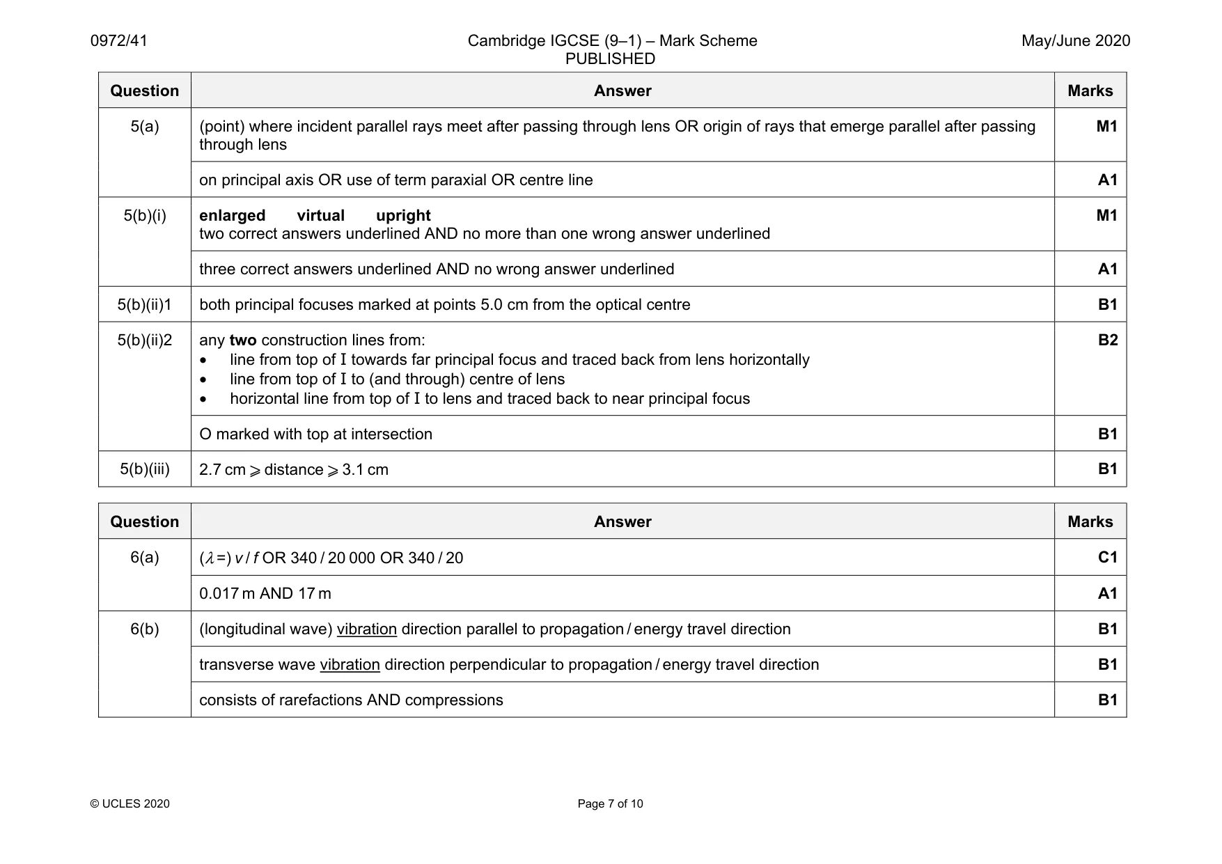
Mark scheme: 5(a) (point) where incident parallel rays meet after passing through lens OR origin of rays that emerge parallel after passing through lens M1 on principal axis OR use of term paraxial OR centre line A1 5(b)(i) enlarged virtual upright two correct answers underlined AND no more than one wrong answer underlined M1 three correct answers underlined AND no wrong answer underlined A1 5(b)(ii)1 both principal focuses marked at points 5.0 cm from the optical centre B1 5(b)(ii)2 any two construction lines from: • line from top of I towards far principal focus and traced back from lens horizontally • line from top of I to (and through) centre of lens • horizontal line from top of I to lens and traced back to near principal focus B2 O marked with top at intersection B1 5(b)(iii) 2.7 cm ⩾ distance ⩾ 3.1 cm B1
Q6 · The speed of sound in air is 340 m / s
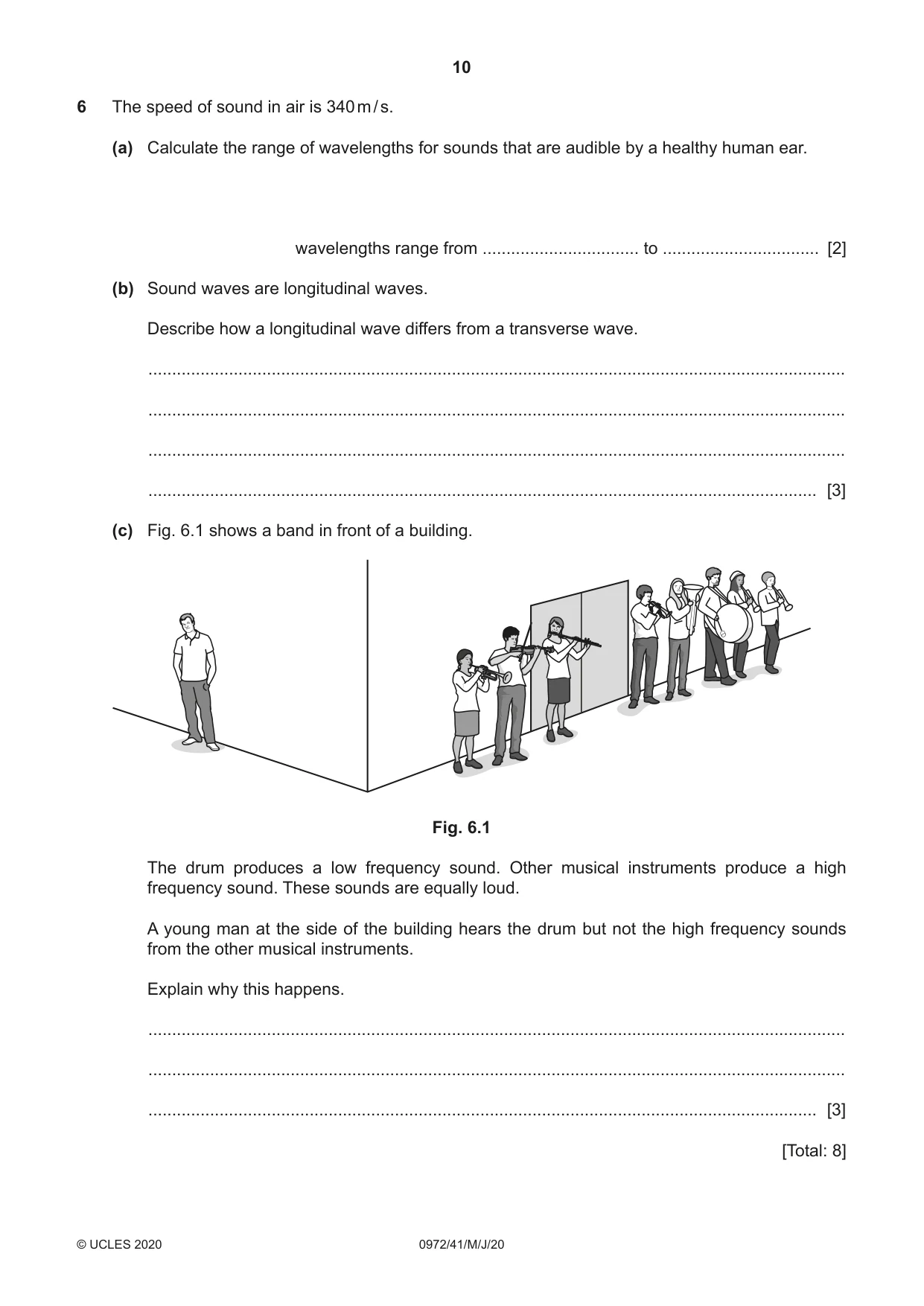
6 The speed of sound in air is 340 m / s. (a) Calculate the range of wavelengths for sounds that are audible by a healthy human ear. wavelengths range from ................................. to ................................. [2] (b) Sound waves are longitudinal waves. Describe how a longitudinal wave differs from a transverse wave. ................................................................................................................................................... ................................................................................................................................................... ................................................................................................................................................... ............................................................................................................................................. [3] (c) Fig. 6.1 shows a band in front of a building. Fig. 6.1 The drum produces a low frequency sound. Other musical instruments produce a high frequency sound. These sounds are equally loud. A young man at the side of the building hears the drum but not the high frequency sounds from the other musical instruments. Explain why this happens. ................................................................................................................................................... ................................................................................................................................................... ............................................................................................................................................. [3] [Total: 8]
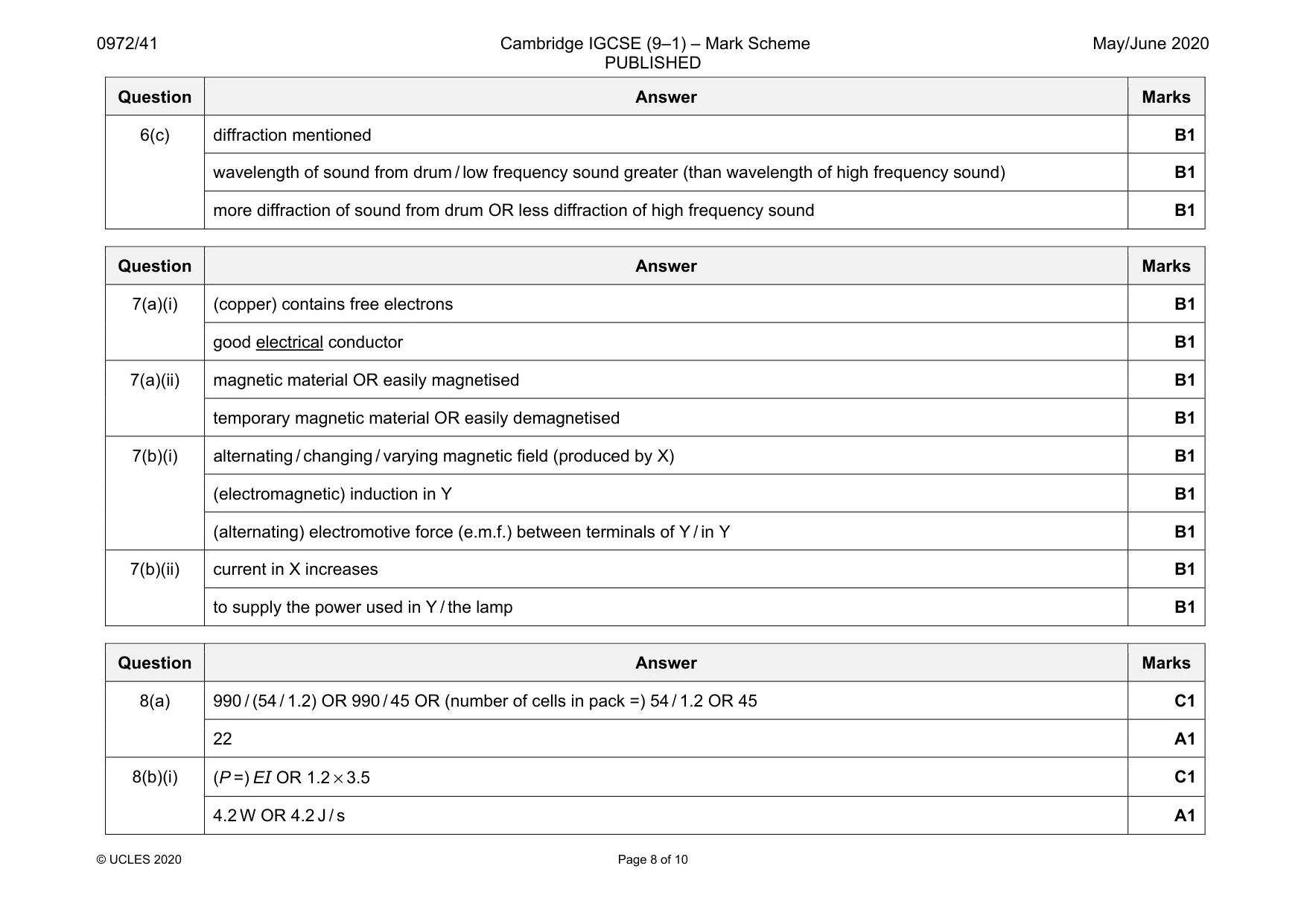
Mark scheme: 6(a) (λ =) v / f OR 340 / 20 000 OR 340 / 20 C1 0.017 m AND 17 m A1 6(b) (longitudinal wave) vibration direction parallel to propagation / energy travel direction B1 transverse wave vibration direction perpendicular to propagation / energy travel direction B1 consists of rarefactions AND compressions B1 Question Answer Marks 6(c) diffraction mentioned B1 wavelength of sound from drum / low frequency sound greater (than wavelength of high frequency sound) B1 more diffraction of sound from drum OR less diffraction of high frequency sound B1
Q7 · An electromagnet consists of a solenoid X that is made of copper wire
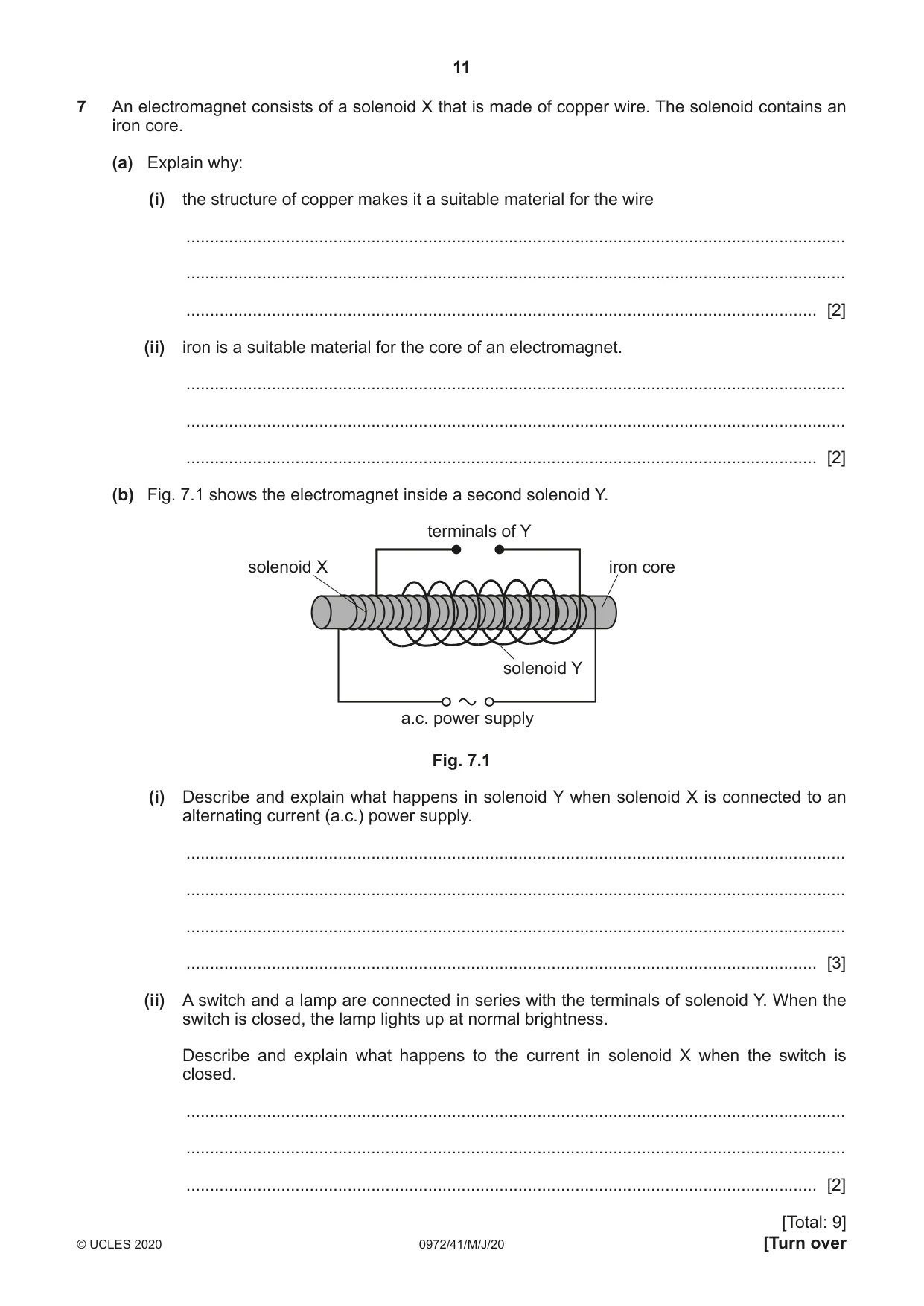
7 An electromagnet consists of a solenoid X that is made of copper wire. The solenoid contains an iron core. (a) Explain why: (i) the structure of copper makes it a suitable material for the wire ........................................................................................................................................... ........................................................................................................................................... ..................................................................................................................................... [2] (ii) iron is a suitable material for the core of an electromagnet. ........................................................................................................................................... ........................................................................................................................................... ..................................................................................................................................... [2] (b) Fig. 7.1 shows the electromagnet inside a second solenoid Y. terminals of Y solenoid X iron core solenoid Y a.c. power supply Fig. 7.1 (i) Describe and explain what happens in solenoid Y when solenoid X is connected to an alternating current (a.c.) power supply. ........................................................................................................................................... ........................................................................................................................................... ........................................................................................................................................... ..................................................................................................................................... [3] (ii) A switch and a lamp are connected in series with the terminals of solenoid Y. When the switch is closed, the lamp lights up at normal brightness. Describe and explain what happens to the current in solenoid X when the switch is closed. ........................................................................................................................................... ........................................................................................................................................... ..................................................................................................................................... [2] [Total: 9]
Mark scheme: 7(a)(i) (copper) contains free electrons B1 good electrical conductor B1 7(a)(ii) magnetic material OR easily magnetised B1 temporary magnetic material OR easily demagnetised B1 7(b)(i) alternating / changing / varying magnetic field (produced by X) B1 (electromagnetic) induction in Y B1 (alternating) electromotive force (e.m.f.) between terminals of Y / in Y B1 7(b)(ii) current in X increases B1 to supply the power used in Y / the lamp B1
Q8 · The power supply used in an electric vehicle contains 990 rechargeable cells each of…
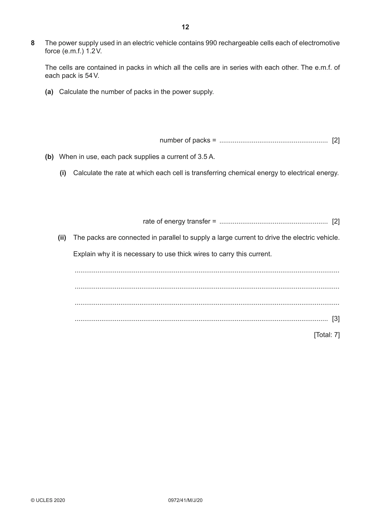
8 The power supply used in an electric vehicle contains 990 rechargeable cells each of electromotive force (e.m.f.) 1.2 V. The cells are contained in packs in which all the cells are in series with each other. The e.m.f. of each pack is 54 V. (a) Calculate the number of packs in the power supply. number of packs = ......................................................... [2] (b) When in use, each pack supplies a current of 3.5 A. (i) Calculate the rate at which each cell is transferring chemical energy to electrical energy. rate of energy transfer = ......................................................... [2] (ii) The packs are connected in parallel to supply a large current to drive the electric vehicle. Explain why it is necessary to use thick wires to carry this current. ........................................................................................................................................... ........................................................................................................................................... ........................................................................................................................................... ..................................................................................................................................... [3] [Total: 7]
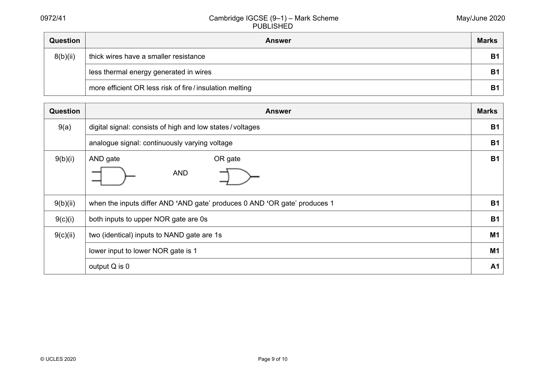
Mark scheme: 8(a) 990 / (54 / 1.2) OR 990 / 45 OR (number of cells in pack =) 54 / 1.2 OR 45 C1 22 A1 8(b)(i) (P =) EI OR 1.2 × 3.5 C1 4.2 W OR 4.2 J / s A1 Question Answer Marks 8(b)(ii) thick wires have a smaller resistance B1 less thermal energy generated in wires B1 more efficient OR less risk of fire / insulation melting B1
Q9 · Describe how a digital signal differs from an analogue signal
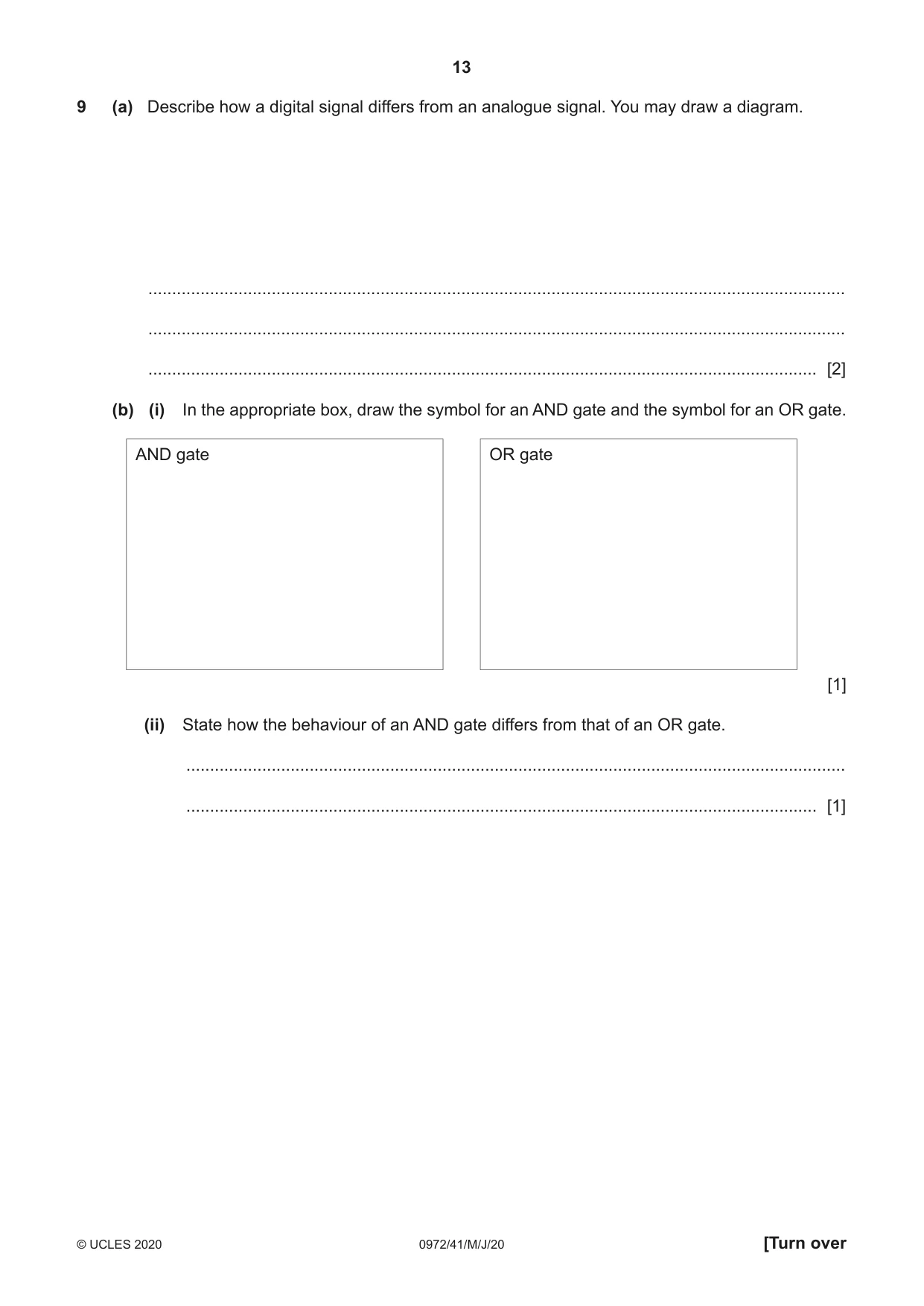
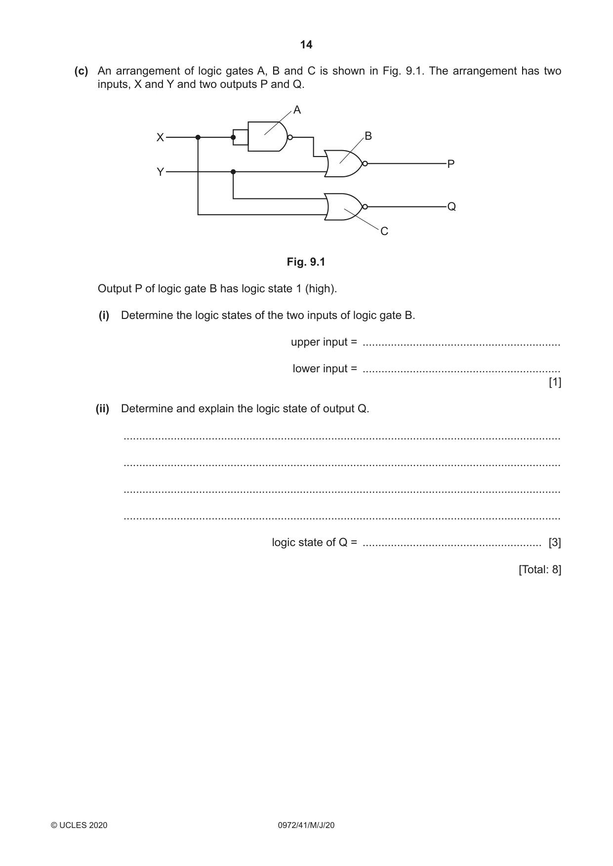
9 (a) Describe how a digital signal differs from an analogue signal. You may draw a diagram. ................................................................................................................................................... ................................................................................................................................................... ............................................................................................................................................. [2] (b) (i) In the appropriate box, draw the symbol for an AND gate and the symbol for an OR gate. AND gate OR gate [1] (ii) State how the behaviour of an AND gate differs from that of an OR gate. ........................................................................................................................................... ..................................................................................................................................... [1] (c) An arrangement of logic gates A, B and C is shown in Fig. 9.1. The arrangement has two inputs, X and Y and two outputs P and Q. A X B P Y Q C Fig. 9.1 Output P of logic gate B has logic state 1 (high). (i) Determine the logic states of the two inputs of logic gate B. upper input = ............................................................... lower input = ............................................................... [1] (ii) Determine and explain the logic state of output Q. ........................................................................................................................................... ........................................................................................................................................... ........................................................................................................................................... ........................................................................................................................................... logic state of Q = ......................................................... [3] [Total: 8]
Mark scheme: 9(a) digital signal: consists of high and low states / voltages B1 analogue signal: continuously varying voltage B1 9(b)(i) AND gate AND OR gate B1 9(b)(ii) when the inputs differ AND ‘AND gate’ produces 0 AND ‘OR gate’ produces 1 B1 9(c)(i) both inputs to upper NOR gate are 0s B1 9(c)(ii) two (identical) inputs to NAND gate are 1s M1 lower input to lower NOR gate is 1 M1 output Q is 0 A1
Q10 · A neutral atom of an isotope of element X
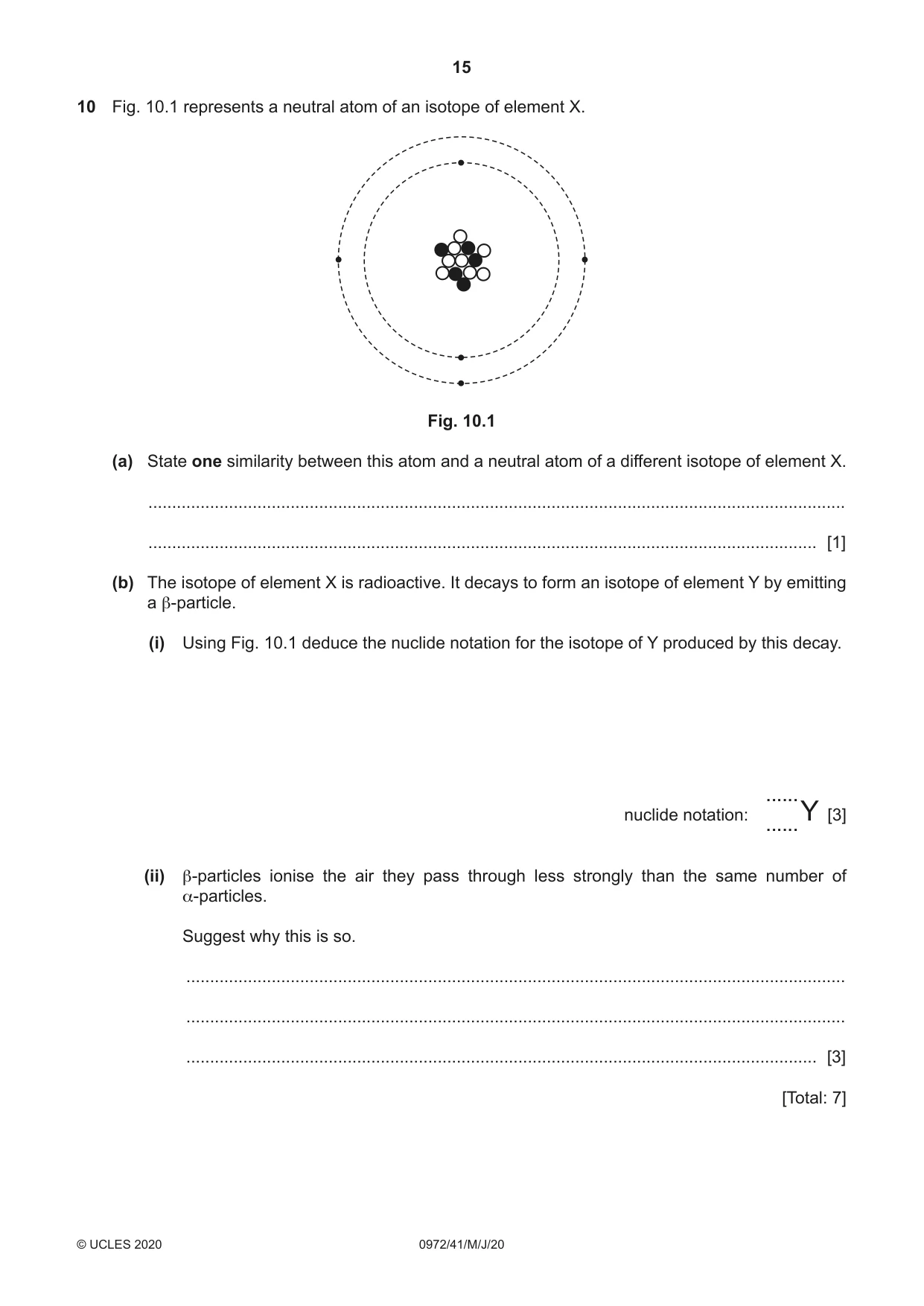
10 Fig. 10.1 represents a neutral atom of an isotope of element X. Fig. 10.1 (a) State one similarity between this atom and a neutral atom of a different isotope of element X. ................................................................................................................................................... ............................................................................................................................................. [1] (b) The isotope of element X is radioactive. It decays to form an isotope of element Y by emitting a β-particle. (i) Using Fig. 10.1 deduce the nuclide notation for the isotope of Y produced by this decay. ...... nuclide notation: [3] ......Y (ii) β-particles ionise the air they pass through less strongly than the same number of α-particles. Suggest why this is so. ........................................................................................................................................... ........................................................................................................................................... ..................................................................................................................................... [3] [Total: 7]
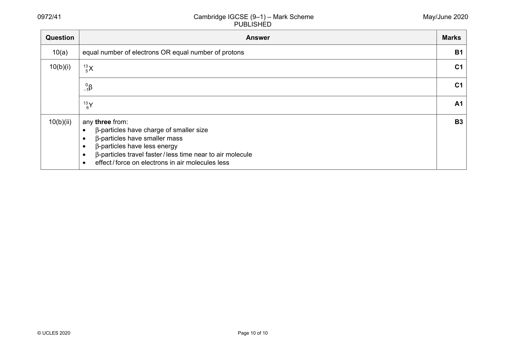
Mark scheme: 10(a) equal number of electrons OR equal number of protons B1 10(b)(i) 13 5X C1 0 1β − C1 13 6Y A1 10(b)(ii) any three from: • β-particles have charge of smaller size • β-particles have smaller mass • β-particles have less energy • β-particles travel faster / less time near to air molecule • effect / force on electrons in air molecules less B3
What was in this paper
The subtopics covered by these 10 questions, and how many questions each got. Open one in a new tab to see every Cambridge question on it.