Cambridge IGCSE Physics (9-1) 0972 — 2024 Oct/Nov Paper 4 · Variant 1
0972/41/O/N/24 · 9 questions · 80 marks · ≈90 min
The question paper and its mark scheme, free to read here and free to download. This is Cambridge’s own paper, exactly as it was sat.
Question paper20 pages
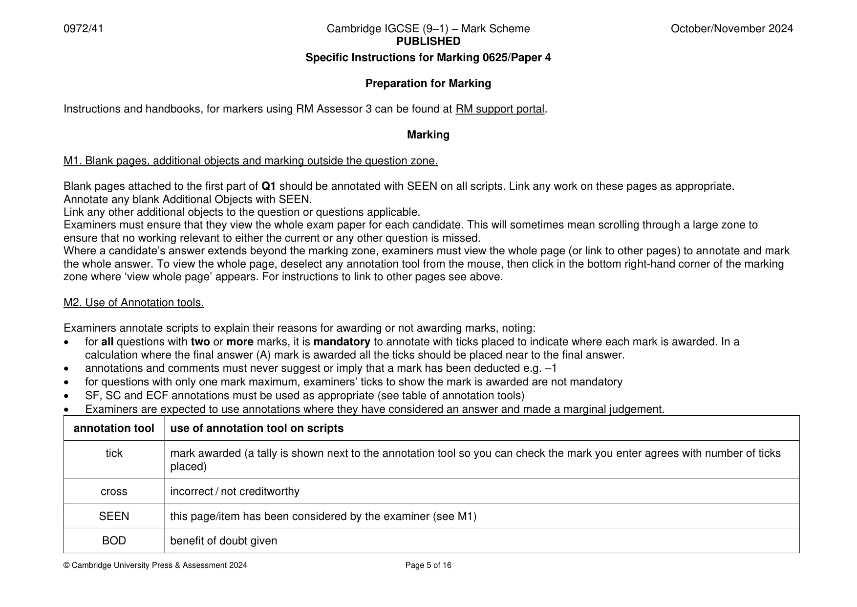
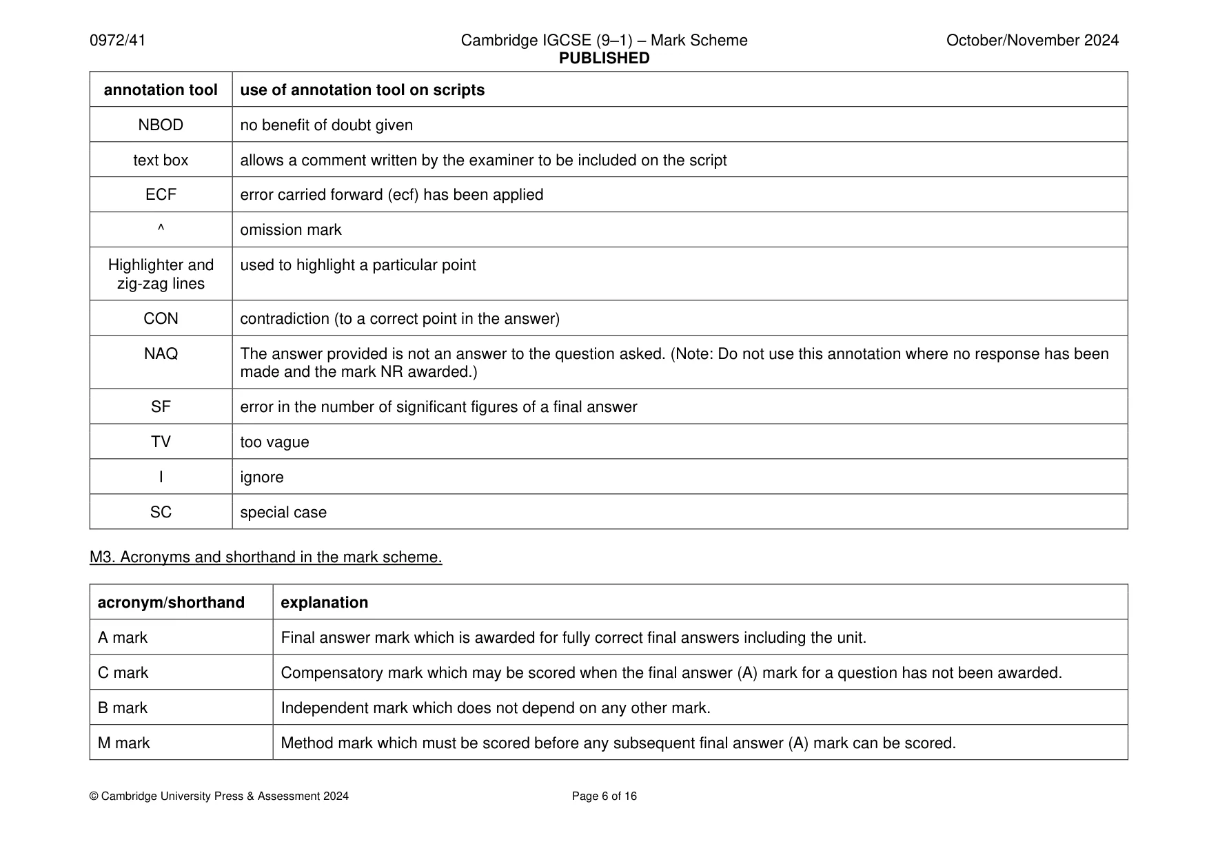
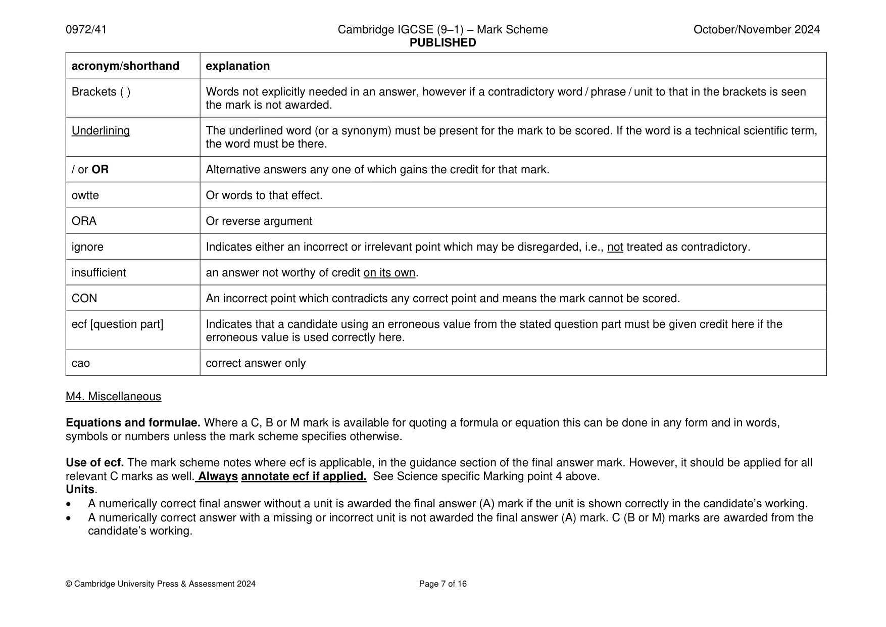
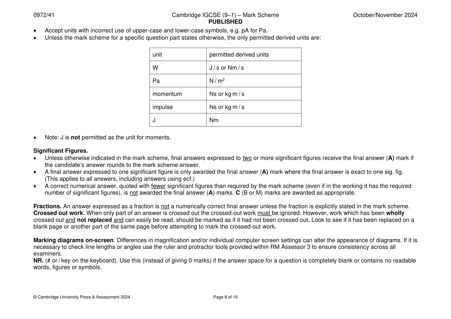
Mark scheme16 pages
Answers below. Sit the paper first if you are practising.
Questions as text
Q1 · A spring is suspended from a clamp
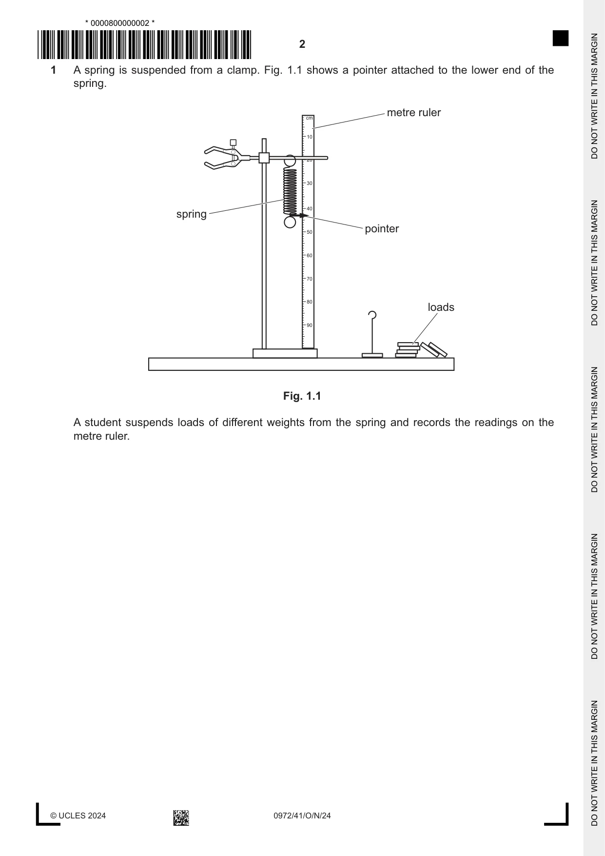
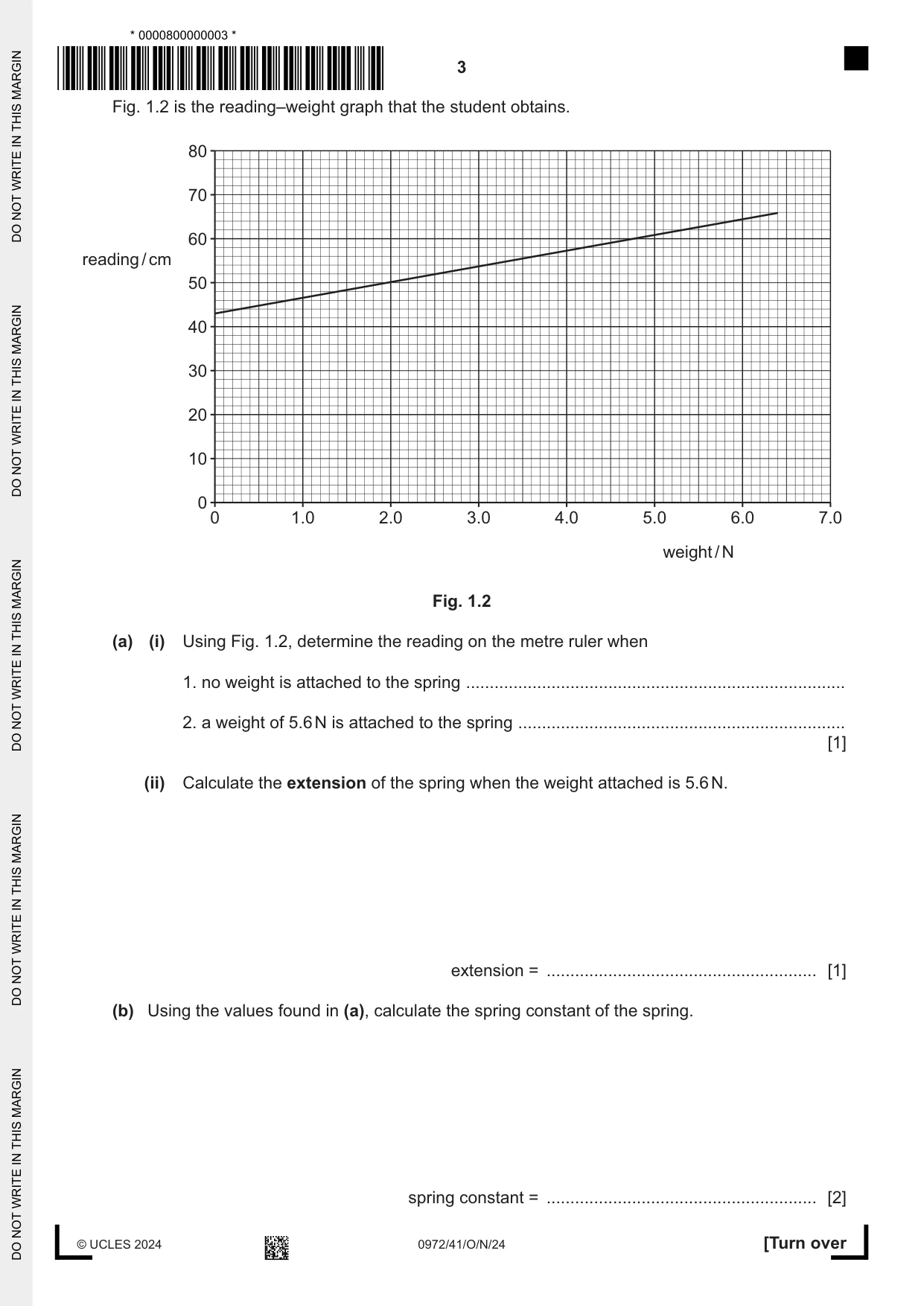
1 A spring is suspended from a clamp. Fig. 1.1 shows a pointer attached to the lower end of the spring. cm metre ruler 10 20 30 spring 40 50 pointer 60 70 80 loads 90 Fig. 1.1 A student suspends loads of different weights from the spring and records the readings on the metre ruler. Fig. 1.2 is the reading–weight graph that the student obtains. 80 70 60 reading / cm 50 40 30 20 10 0 0 1.0 2.0 3.0 4.0 5.0 6.0 7.0 weight / N Fig. 1.2 (a) (i) Using Fig. 1.2, determine the reading on the metre ruler when 1. no weight is attached to the spring ................................................................................ 2. a weight of 5.6 N is attached to the spring ..................................................................... [1] (ii) Calculate the extension of the spring when the weight attached is 5.6 N. extension = ......................................................... [1] (b) Using the values found in (a), calculate the spring constant of the spring. spring constant = ......................................................... [2] (c) An object of mass 0.50 kg is attached to the spring. (i) Calculate the weight of the object. weight = ......................................................... [1] (ii) The object is pulled downwards until the tension in the spring is 6.5 N. The object is released. Calculate the acceleration of the object immediately after it is released. acceleration = ......................................................... [3] [Total: 8]
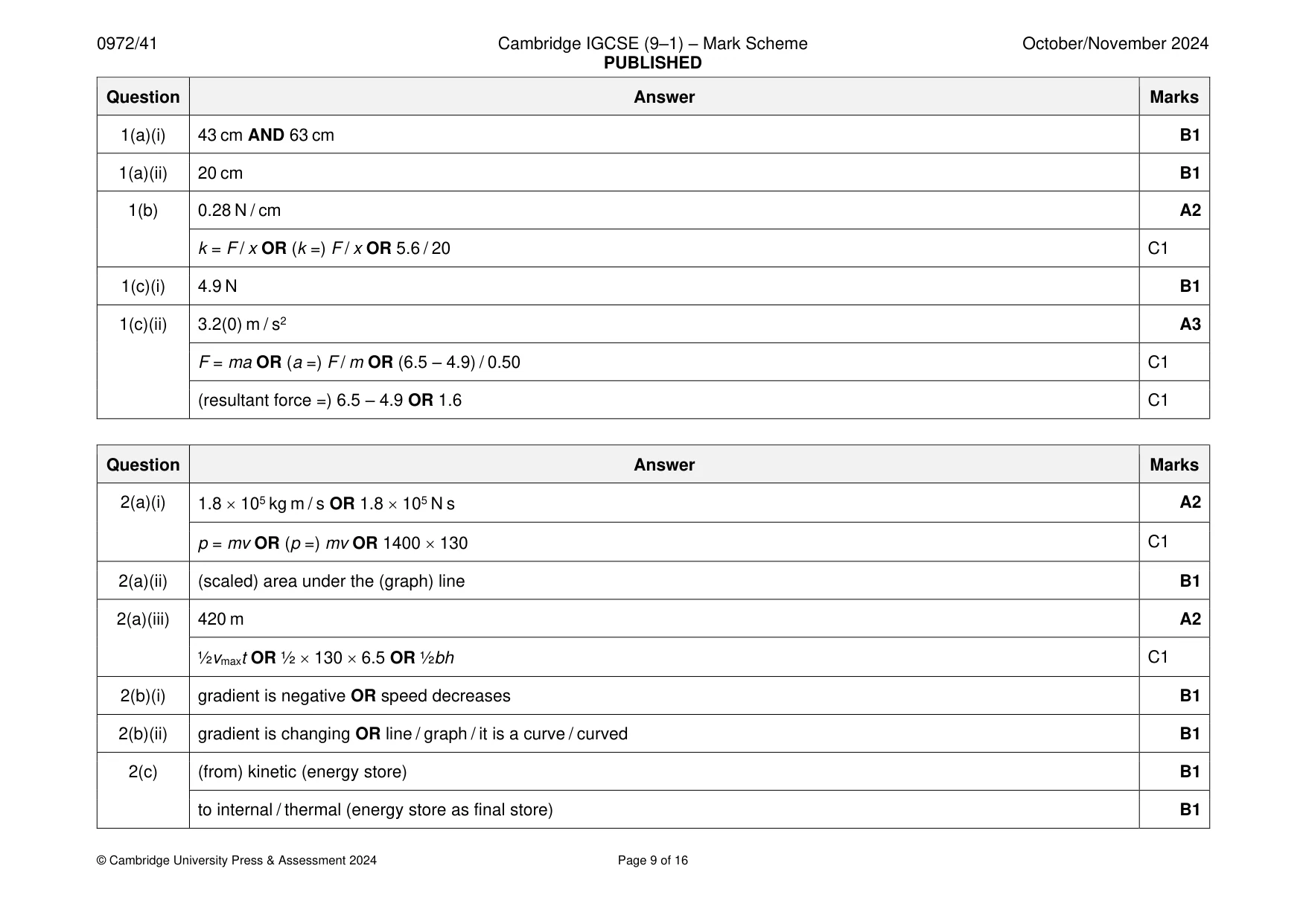
Mark scheme: Question Answer Marks 1(a)(i) 43 cm AND 63 cm B1 1(a)(ii) 20 cm B1 1(b) 0.28 N / cm A2 k = F / x OR (k =) F / x OR 5.6 / 20 C1 1(c)(i) 4.9 N B1 1(c)(ii) 3.2(0) m / s2 A3 F = ma OR (a =) F / m OR (6.5 – 4.9) / 0.50 C1 (resultant force =) 6.5 – 4.9 OR 1.6 C1
Q2 · A drag car is a racing car that is powered by a rocket engine
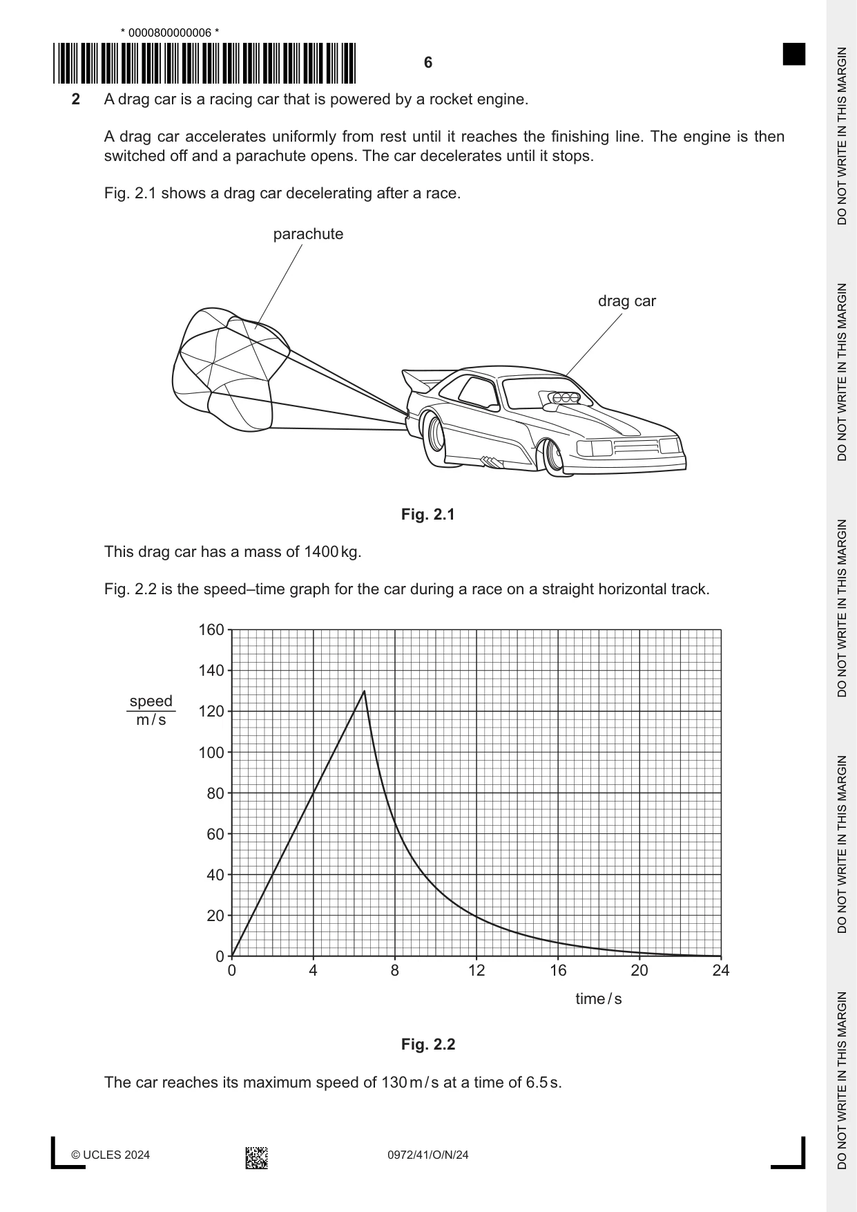
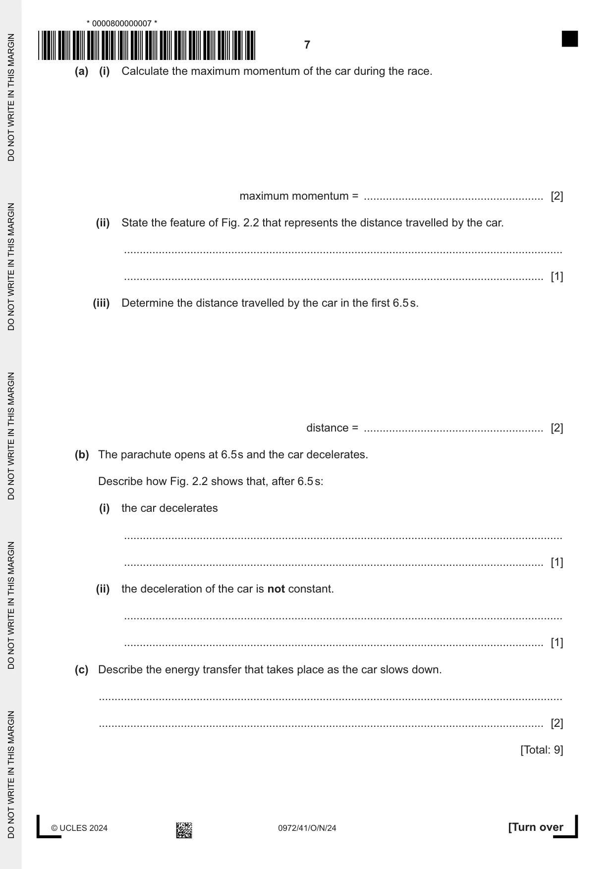
2 A drag car is a racing car that is powered by a rocket engine. A drag car accelerates uniformly from rest until it reaches the finishing line. The engine is then switched off and a parachute opens. The car decelerates until it stops. Fig. 2.1 shows a drag car decelerating after a race. parachute drag car Fig. 2.1 This drag car has a mass of 1400 kg. Fig. 2.2 is the speed–time graph for the car during a race on a straight horizontal track. 160 140 speed 120 m / s 100 80 60 40 20 0 0 4 8 12 16 20 24 time / s Fig. 2.2 The car reaches its maximum speed of 130 m / s at a time of 6.5 s. (a) (i) Calculate the maximum momentum of the car during the race. maximum momentum = ......................................................... [2] (ii) State the feature of Fig. 2.2 that represents the distance travelled by the car. ........................................................................................................................................... ..................................................................................................................................... [1] (iii) Determine the distance travelled by the car in the first 6.5 s. distance = ......................................................... [2] (b) The parachute opens at 6.5 s and the car decelerates. Describe how Fig. 2.2 shows that, after 6.5 s: (i) the car decelerates ........................................................................................................................................... ..................................................................................................................................... [1] (ii) the deceleration of the car is not constant. ........................................................................................................................................... ..................................................................................................................................... [1] (c) Describe the energy transfer that takes place as the car slows down. ................................................................................................................................................... ............................................................................................................................................. [2] [Total: 9]
Mark scheme: 2(a)(i) 1.8 105 kg m / s OR 1.8 105 N s A2 p = mv OR (p =) mv OR 1400 130 C1 2(a)(ii) (scaled) area under the (graph) line B1 2(a)(iii) 420 m A2 ½vmaxt OR ½ 130 6.5 OR ½bh C1 2(b)(i) gradient is negative OR speed decreases B1 2(b)(ii) gradient is changing OR line / graph / it is a curve / curved B1 2(c) (from) kinetic (energy store) B1 to internal / thermal (energy store as final store) B1
Q3 · Define the moment of a force and describe the effect that it measures
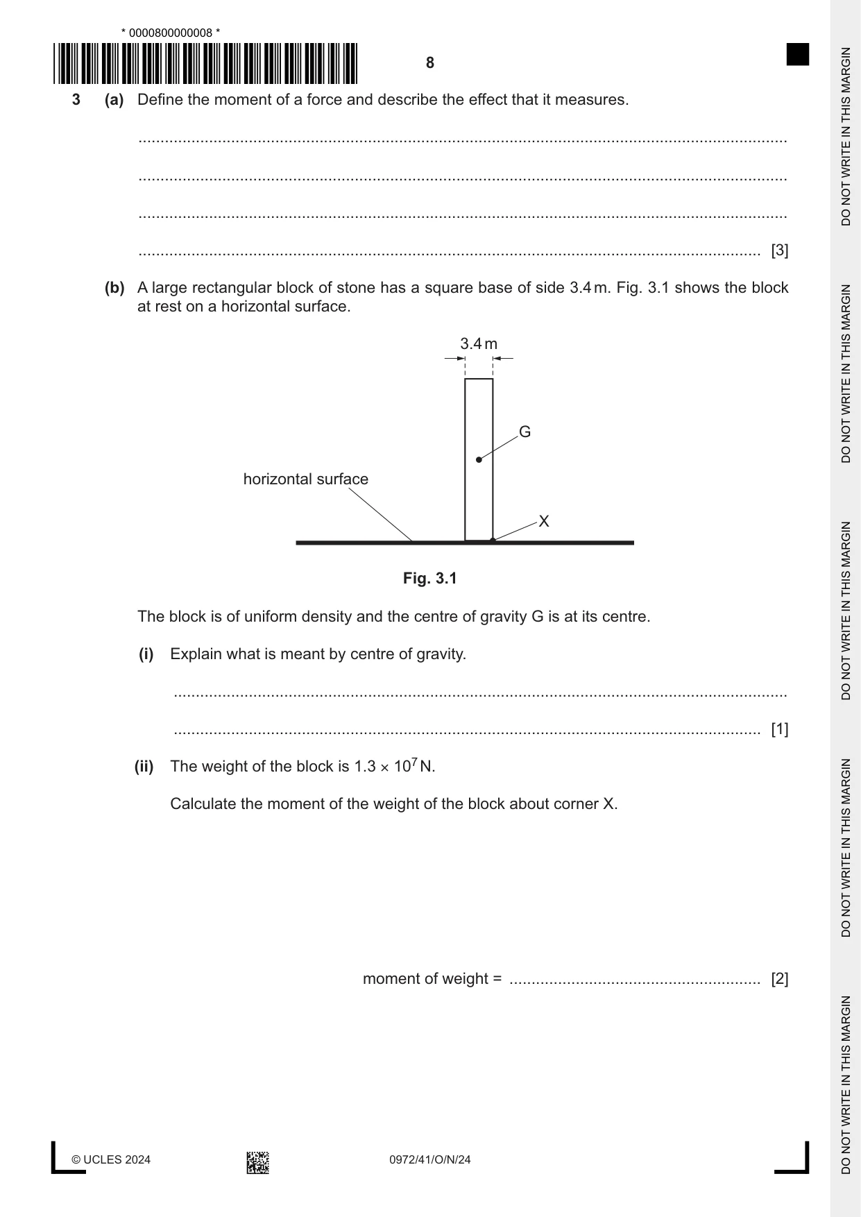
3 (a) Define the moment of a force and describe the effect that it measures. ................................................................................................................................................... ................................................................................................................................................... ................................................................................................................................................... ............................................................................................................................................. [3] (b) A large rectangular block of stone has a square base of side 3.4 m. Fig. 3.1 shows the block at rest on a horizontal surface. 3.4 m G horizontal surface X Fig. 3.1 The block is of uniform density and the centre of gravity G is at its centre. (i) Explain what is meant by centre of gravity. ........................................................................................................................................... ..................................................................................................................................... [1] (ii) The weight of the block is 1.3 × 10⁷ N. Calculate the moment of the weight of the block about corner X. moment of weight = ......................................................... [2] (c) The block shown in Fig. 3.1 is in equilibrium. State the two different conditions that apply when an object is in equilibrium. 1 ................................................................................................................................................ 2 ................................................................................................................................................ [2] [Total: 8]
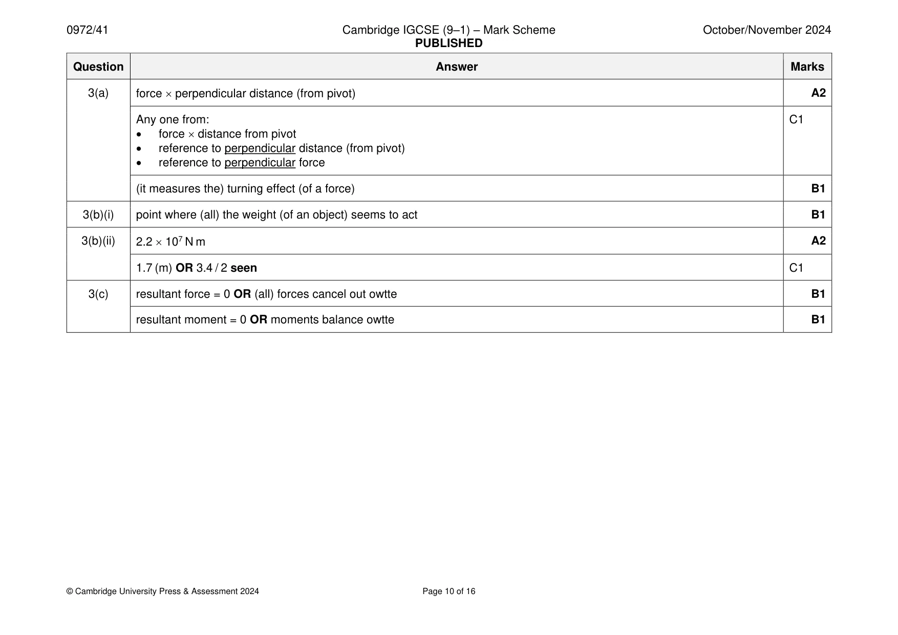
Mark scheme: 3(a) force perpendicular distance (from pivot) A2 Any one from: C1 • force distance from pivot • reference to perpendicular distance (from pivot) • reference to perpendicular force (it measures the) turning effect (of a force) B1 3(b)(i) point where (all) the weight (of an object) seems to act B1 3(b)(ii) 2.2 107 N m A2 1.7 (m) OR 3.4 / 2 seen C1 3(c) resultant force = 0 OR (all) forces cancel out owtte B1 resultant moment = 0 OR moments balance owtte B1
Q4 · Describe an experiment to determine the specific heat capacity of aluminium
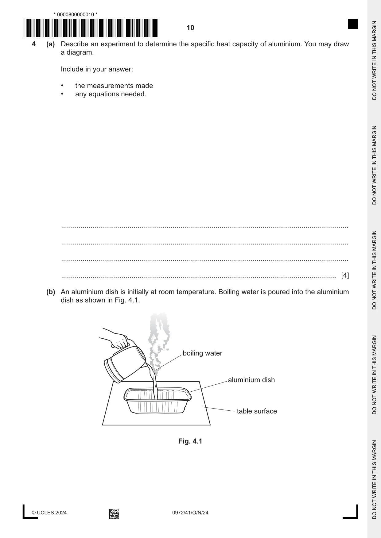
4 (a) Describe an experiment to determine the specific heat capacity of aluminium. You may draw a diagram. Include in your answer: • the measurements made • any equations needed. ................................................................................................................................................... ................................................................................................................................................... ................................................................................................................................................... ............................................................................................................................................. [4] (b) An aluminium dish is initially at room temperature. Boiling water is poured into the aluminium dish as shown in Fig. 4.1. boiling water aluminium dish table surface Fig. 4.1 (i) Explain why, after a short time, the dish and the water are the same temperature. ........................................................................................................................................... ........................................................................................................................................... ........................................................................................................................................... ..................................................................................................................................... [3] (ii) Explain, in terms of its particles, why the aluminium expands as the boiling water is poured into the dish. ........................................................................................................................................... ........................................................................................................................................... ..................................................................................................................................... [2] (iii) The water in the dish evaporates. Explain, in terms of the water molecules, what is meant by evaporation. ........................................................................................................................................... ........................................................................................................................................... ..................................................................................................................................... [2] [Total: 11]
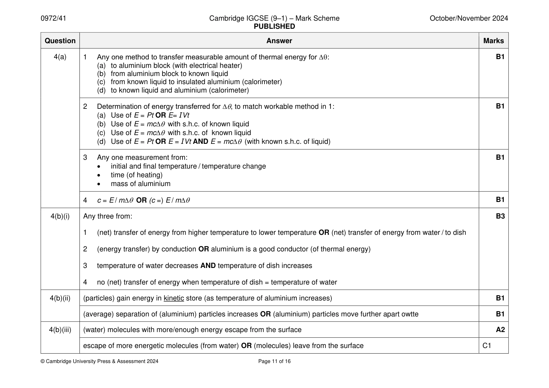
Mark scheme: 4(a) 1 Any one method to transfer measurable amount of thermal energy for ∆: B1 (a) to aluminium block (with electrical heater) (b) from aluminium block to known liquid (c) from known liquid to insulated aluminium (calorimeter) (d) to known liquid and aluminium (calorimeter) 2 Determination of energy transferred for ∆, to match workable method in 1: B1 (a) Use of E = Pt OR E= IVt (b) Use of E = mc with s.h.c. of known liquid (c) Use of E = mc with s.h.c. of known liquid (d) Use of E = Pt OR E = IVt AND E = mc (with known s.h.c. of liquid) 3 Any one measurement from: B1 • initial and final temperature / temperature change • time (of heating) • mass of aluminium 4 c = E / m OR (c =) E / m B1 4(b)(i) Any three from: B3 1 (net) transfer of energy from higher temperature to lower temperature OR (net) transfer of energy from water / to dish 2 (energy transfer) by conduction OR aluminium is a good conductor (of thermal energy) 3 temperature of water decreases AND temperature of dish increases 4 no (net) transfer of energy when temperature of dish = temperature of water 4(b)(ii) (particles) gain energy in kinetic store (as temperature of aluminium increases) B1 (average) separation of (aluminium) particles increases OR (aluminium) particles move further apart owtte B1 4(b)(iii) (water) molecules with more/enough energy escape from the surface A2 escape of more energetic molecules (from water) OR (molecules) leave from the surface C1
Q5 · A loudspeaker produces a sound wave in air
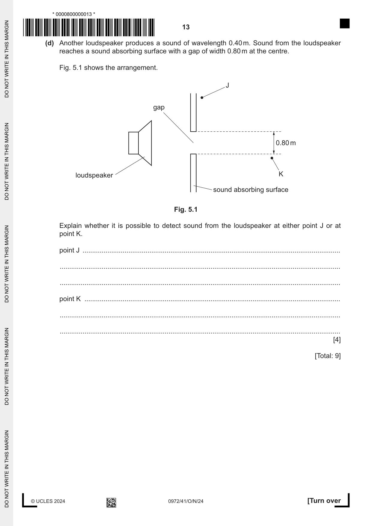
5 A loudspeaker produces a sound wave in air. The distance between the centre of a compression and the centre of a neighbouring rarefaction is 0.10 m. (a) Calculate the wavelength of the sound wave. wavelength = ......................................................... [1] (b) State a typical value for the speed of sound in air. ............................................................................................................................................. [1] (c) (i) Calculate the frequency of the sound from the loudspeaker. frequency = ......................................................... [2] (ii) Explain whether the sound from the loudspeaker is audible to a human with normal hearing. ........................................................................................................................................... ..................................................................................................................................... [1] (d) Another loudspeaker produces a sound of wavelength 0.40 m. Sound from the loudspeaker reaches a sound absorbing surface with a gap of width 0.80 m at the centre. Fig. 5.1 shows the arrangement. J gap 0.80 m loudspeaker K sound absorbing surface Fig. 5.1 Explain whether it is possible to detect sound from the loudspeaker at either point J or at point K. point J ....................................................................................................................................... ................................................................................................................................................... ................................................................................................................................................... point K ...................................................................................................................................... ................................................................................................................................................... ................................................................................................................................................... [4] [Total: 9]
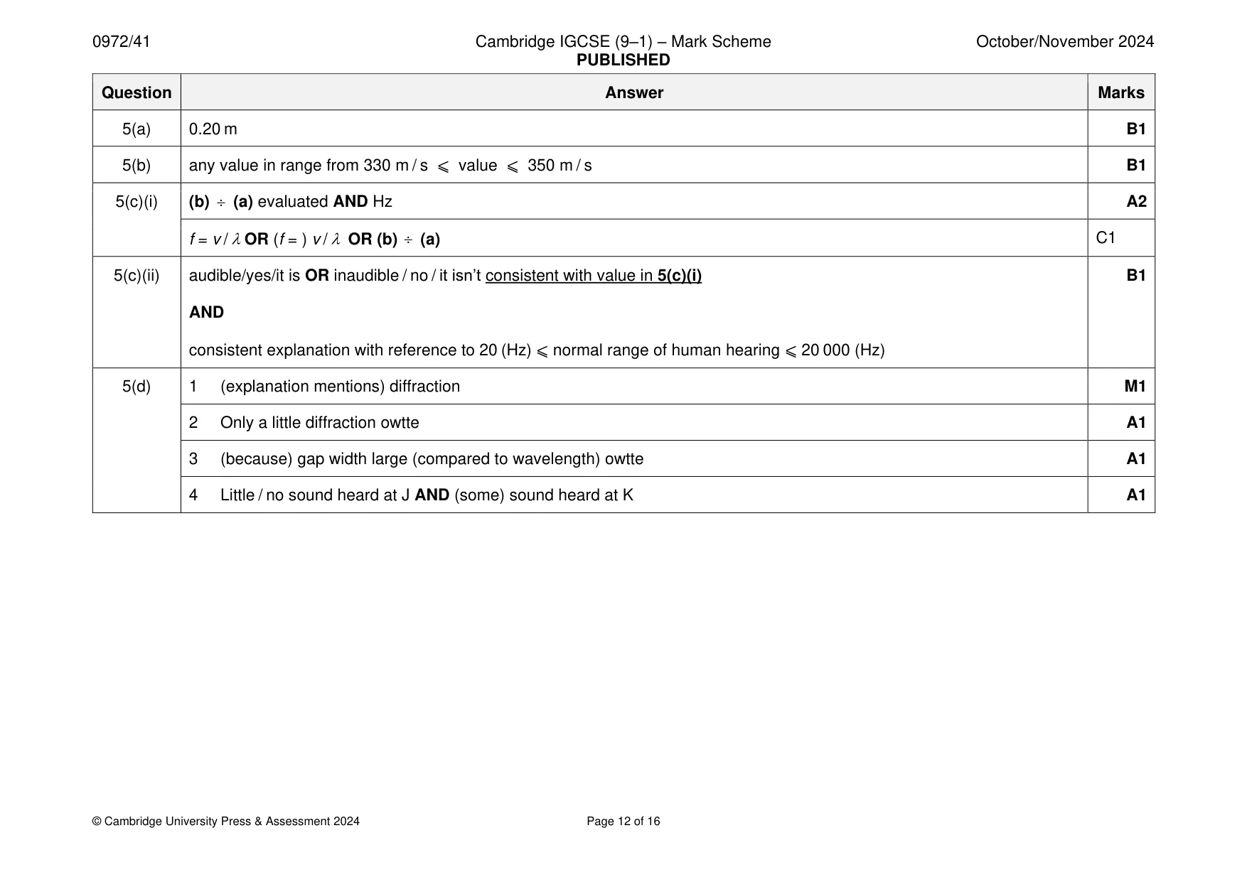
Mark scheme: 5(a) 0.20 m B1 5(b) any value in range from 330 m / s ⩽ value ⩽ 350 m / s B1 5(c)(i) (b) (a) evaluated AND Hz A2 f = v / OR (f = ) v / OR (b) (a) C1 5(c)(ii) audible/yes/it is OR inaudible / no / it isn’t consistent with value in 5(c)(i) B1 AND consistent explanation with reference to 20 (Hz) ⩽ normal range of human hearing ⩽ 20 000 (Hz) 5(d) 1 (explanation mentions) diffraction M1 2 Only a little diffraction owtte A1 3 (because) gap width large (compared to wavelength) owtte A1 4 Little / no sound heard at J AND (some) sound heard at K A1
Q6 · A potential divider is made by connecting a light-dependent resistor (LDR) and a…
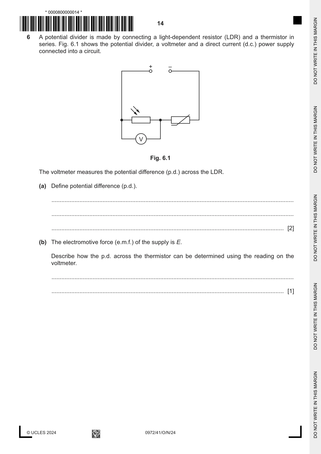
6 A potential divider is made by connecting a light-dependent resistor (LDR) and a thermistor in series. Fig. 6.1 shows the potential divider, a voltmeter and a direct current (d.c.) power supply connected into a circuit. + – V Fig. 6.1 The voltmeter measures the potential difference (p.d.) across the LDR. (a) Define potential difference (p.d.). ................................................................................................................................................... ................................................................................................................................................... ............................................................................................................................................. [2] (b) The electromotive force (e.m.f.) of the supply is E. Describe how the p.d. across the thermistor can be determined using the reading on the voltmeter. ................................................................................................................................................... ............................................................................................................................................. [1] (c) The resistance of the LDR decreases and the resistance of the thermistor increases. (i) State what has happened to the light intensity incident on the LDR and the temperature of the thermistor. intensity of incident light on LDR: ...................................................................................... temperature of thermistor: ................................................................................................. [1] (ii) Explain what happens to the reading on the voltmeter. ........................................................................................................................................... ........................................................................................................................................... ........................................................................................................................................... ..................................................................................................................................... [3] [Total: 7]
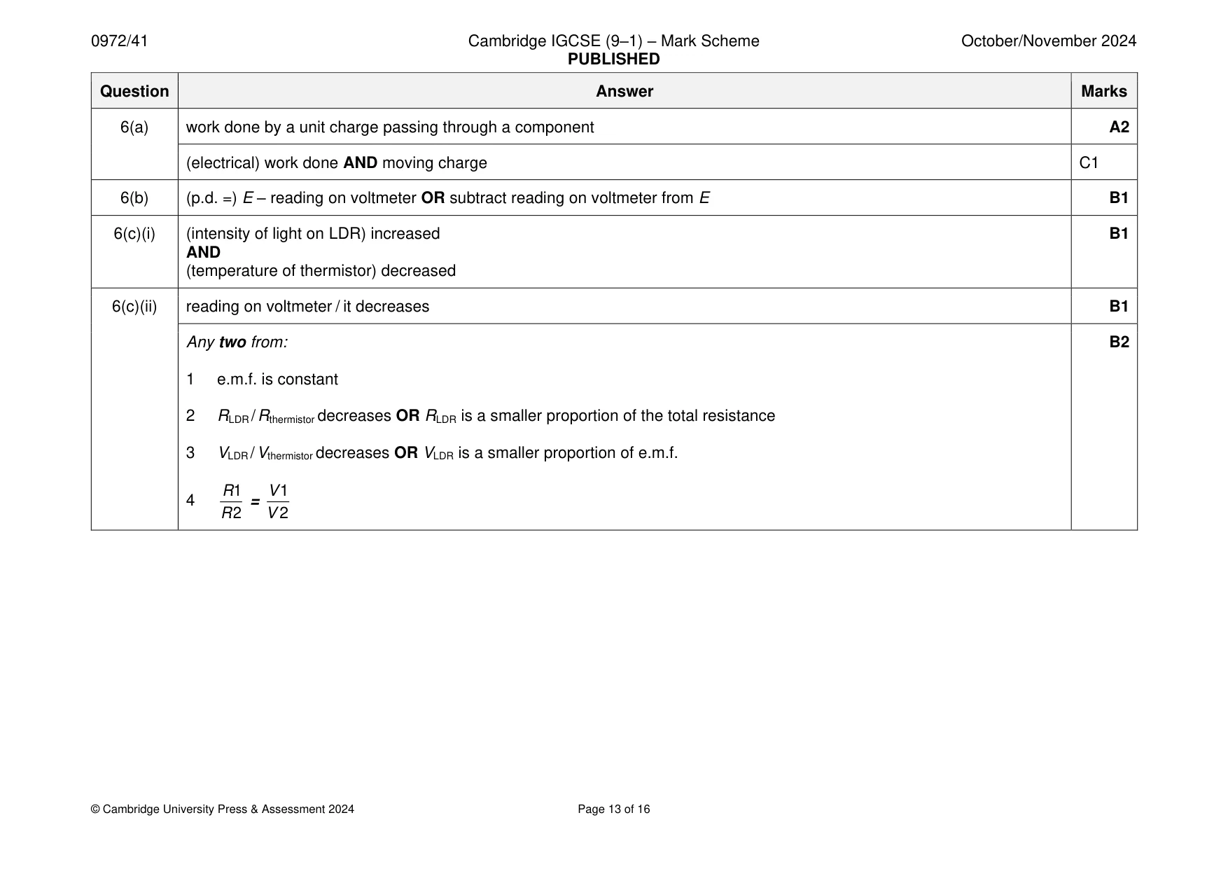
Mark scheme: 6(a) work done by a unit charge passing through a component A2 (electrical) work done AND moving charge C1 6(b) (p.d. =) E – reading on voltmeter OR subtract reading on voltmeter from E B1 6(c)(i) (intensity of light on LDR) increased B1 AND (temperature of thermistor) decreased 6(c)(ii) reading on voltmeter / it decreases B1 Any two from: B2 1 e.m.f. is constant 2 RLDR / Rthermistor decreases OR RLDR is a smaller proportion of the total resistance 3 VLDR / Vthermistor decreases OR VLDR is a smaller proportion of e.m.f. R 1 V 1 4 = R 2 V 2
Q7 · A solid bar is inside a copper solenoid
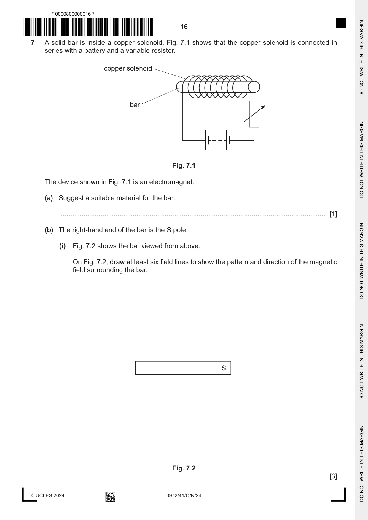
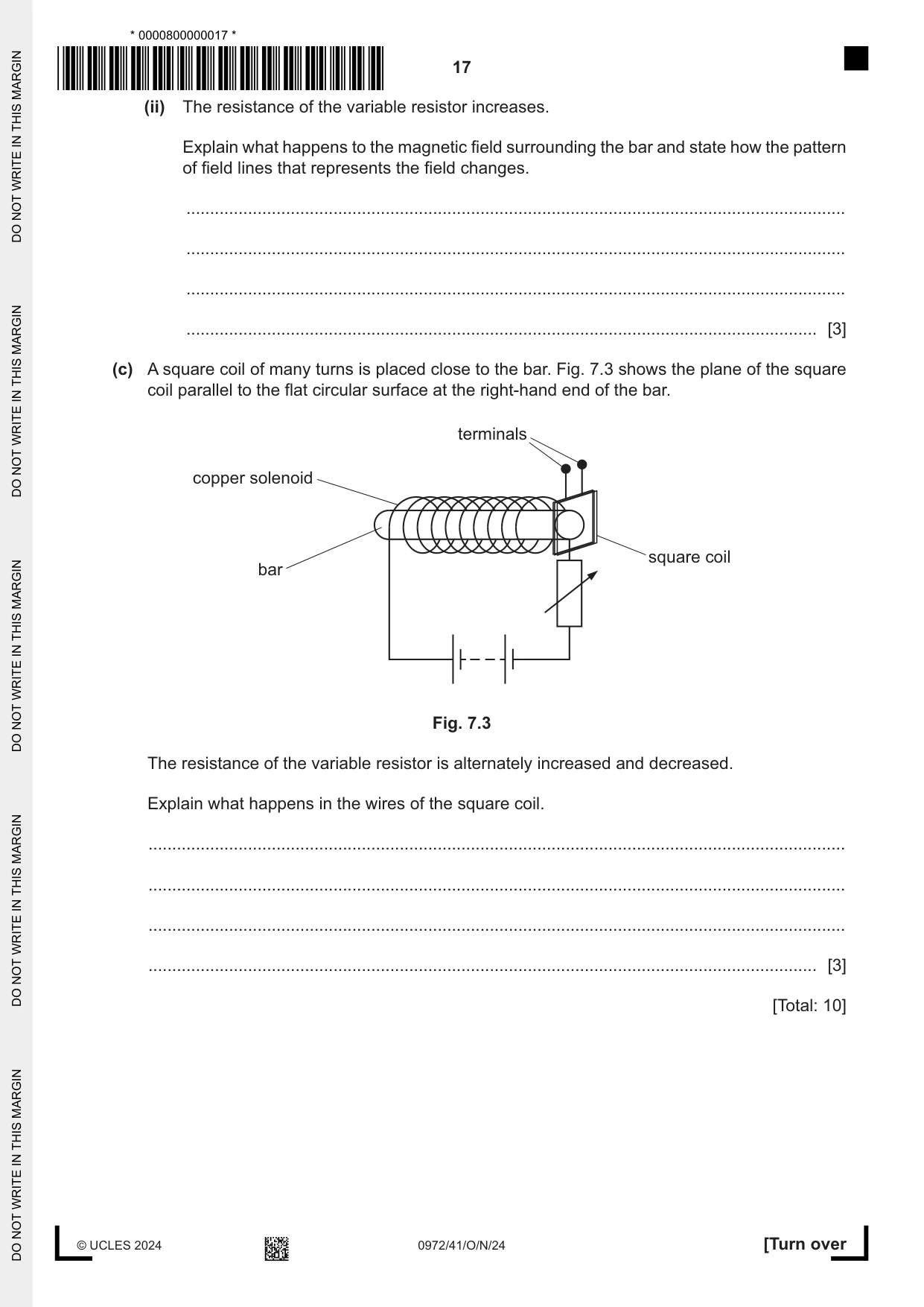
7 A solid bar is inside a copper solenoid. Fig. 7.1 shows that the copper solenoid is connected in series with a battery and a variable resistor. copper solenoid bar Fig. 7.1 The device shown in Fig. 7.1 is an electromagnet. (a) Suggest a suitable material for the bar. ............................................................................................................................................. [1] (b) The right-hand end of the bar is the S pole. (i) Fig. 7.2 shows the bar viewed from above. On Fig. 7.2, draw at least six field lines to show the pattern and direction of the magnetic field surrounding the bar. S Fig. 7.2 [3] (ii) The resistance of the variable resistor increases. Explain what happens to the magnetic field surrounding the bar and state how the pattern of field lines that represents the field changes. ........................................................................................................................................... ........................................................................................................................................... ........................................................................................................................................... ..................................................................................................................................... [3] (c) A square coil of many turns is placed close to the bar. Fig. 7.3 shows the plane of the square coil parallel to the flat circular surface at the right-hand end of the bar. terminals copper solenoid square coil bar Fig. 7.3 The resistance of the variable resistor is alternately increased and decreased. Explain what happens in the wires of the square coil. ................................................................................................................................................... ................................................................................................................................................... ................................................................................................................................................... ............................................................................................................................................. [3] [Total: 10]
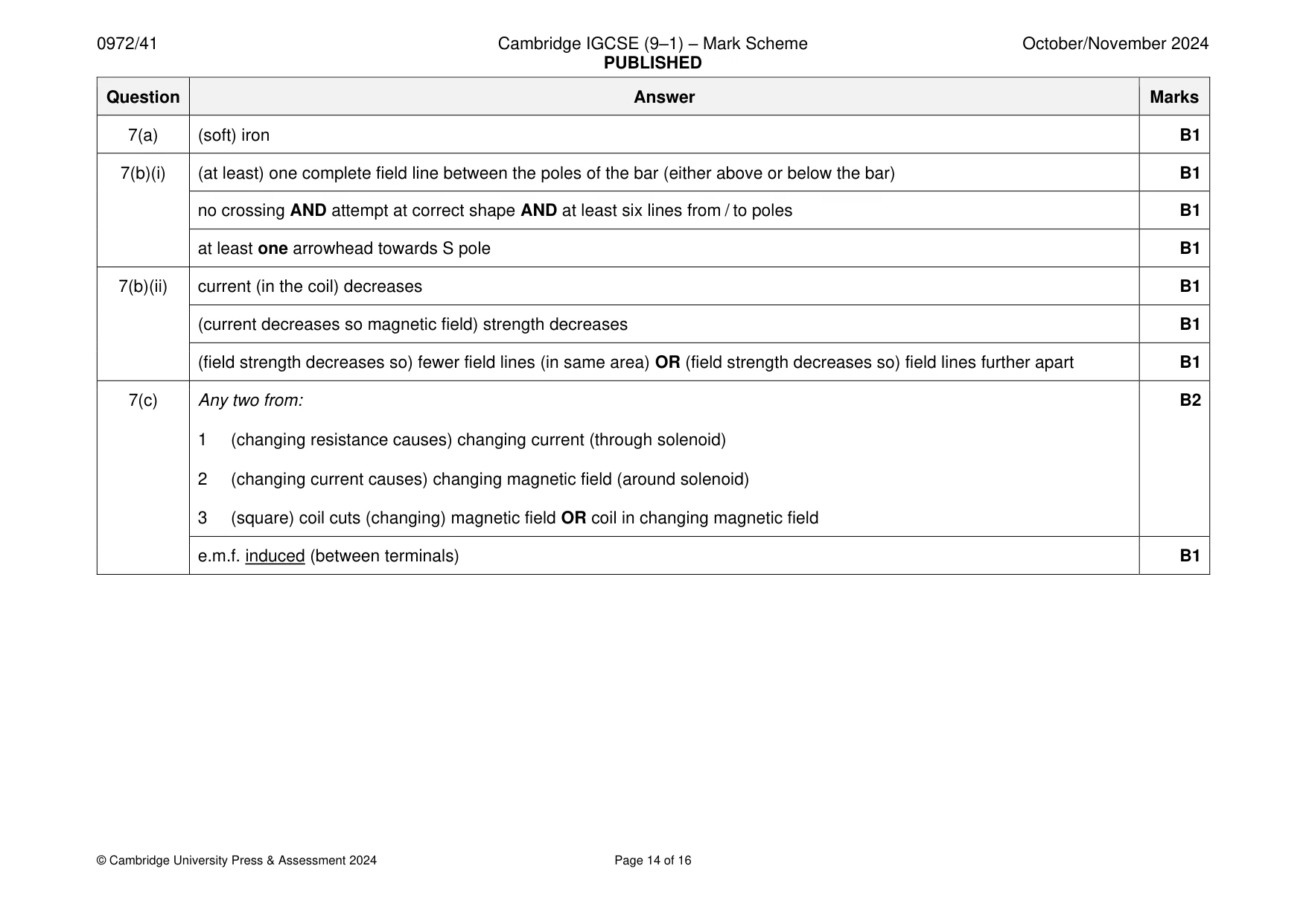
Mark scheme: 7(a) (soft) iron B1 7(b)(i) (at least) one complete field line between the poles of the bar (either above or below the bar) B1 no crossing AND attempt at correct shape AND at least six lines from / to poles B1 at least one arrowhead towards S pole B1 7(b)(ii) current (in the coil) decreases B1 (current decreases so magnetic field) strength decreases B1 (field strength decreases so) fewer field lines (in same area) OR (field strength decreases so) field lines further apart B1 7(c) Any two from: B2 1 (changing resistance causes) changing current (through solenoid) 2 (changing current causes) changing magnetic field (around solenoid) 3 (square) coil cuts (changing) magnetic field OR coil in changing magnetic field e.m.f. induced (between terminals) B1
Q8 · The nuclide notation for the radioactive isotope carbon-14 is 146C
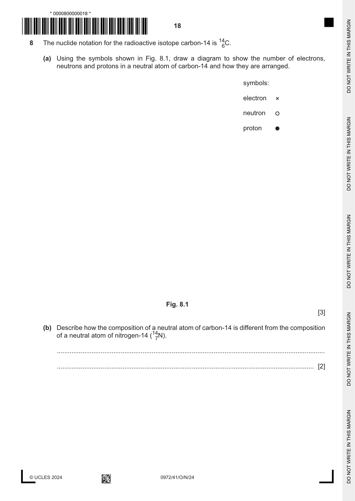
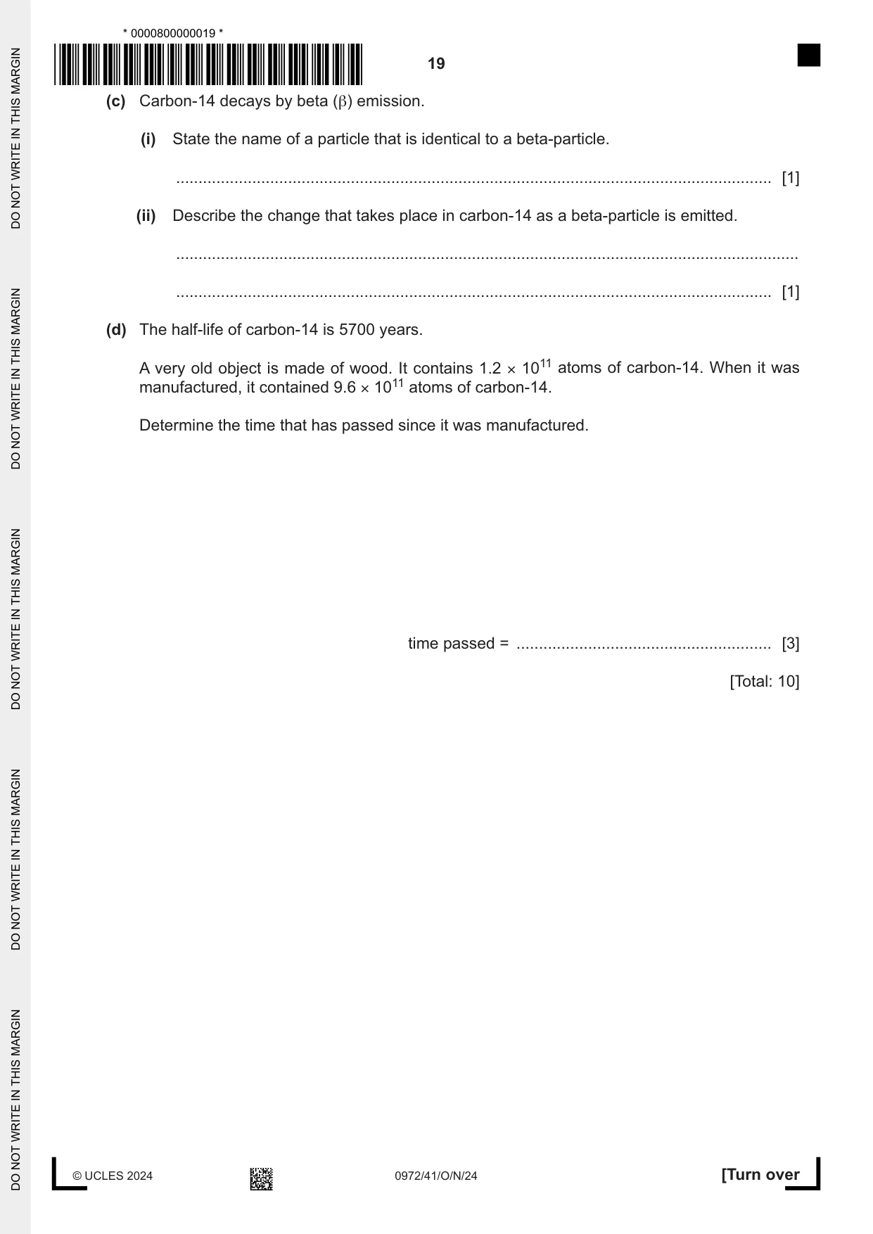
8 The nuclide notation for the radioactive isotope carbon-14 is 146C. (a) Using the symbols shown in Fig. 8.1, draw a diagram to show the number of electrons, neutrons and protons in a neutral atom of carbon-14 and how they are arranged. symbols: electron neutron proton Fig. 8.1 [3] (b) Describe how the composition of a neutral atom of carbon-14 is different from the composition of a neutral atom of nitrogen-14 (147N). ................................................................................................................................................... ............................................................................................................................................. [2] (c) Carbon-14 decays by beta (β) emission. (i) State the name of a particle that is identical to a beta-particle. ..................................................................................................................................... [1] (ii) Describe the change that takes place in carbon-14 as a beta-particle is emitted. ........................................................................................................................................... ..................................................................................................................................... [1] (d) The half-life of carbon-14 is 5700 years. A very old object is made of wood. It contains 1.2 × 10¹¹ atoms of carbon-14. When it was manufactured, it contained 9.6 × 10¹¹ atoms of carbon-14. Determine the time that has passed since it was manufactured. time passed = ......................................................... [3] [Total: 10]
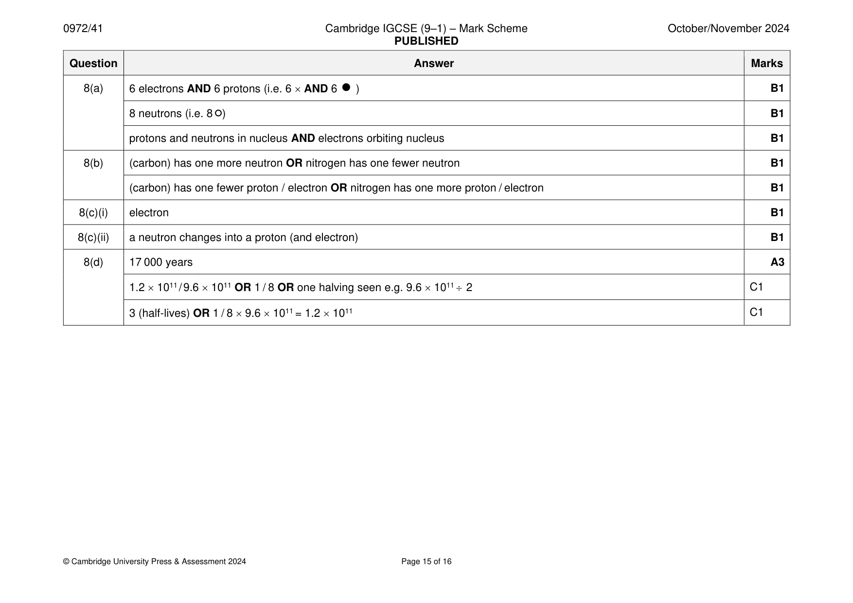
Mark scheme: 8(a) 6 electrons AND 6 protons (i.e. 6 AND 6 ) B1 8 neutrons (i.e. 8 ) B1 protons and neutrons in nucleus AND electrons orbiting nucleus B1 8(b) (carbon) has one more neutron OR nitrogen has one fewer neutron B1 (carbon) has one fewer proton / electron OR nitrogen has one more proton / electron B1 8(c)(i) electron B1 8(c)(ii) a neutron changes into a proton (and electron) B1 8(d) 17 000 years A3 1.2 1011 / 9.6 1011 OR 1 / 8 OR one halving seen e.g. 9.6 1011 2 C1 3 (half-lives) OR 1 / 8 9.6 1011 = 1.2 1011 C1
Q9 · The Milky Way is the galaxy in which the Solar System is located
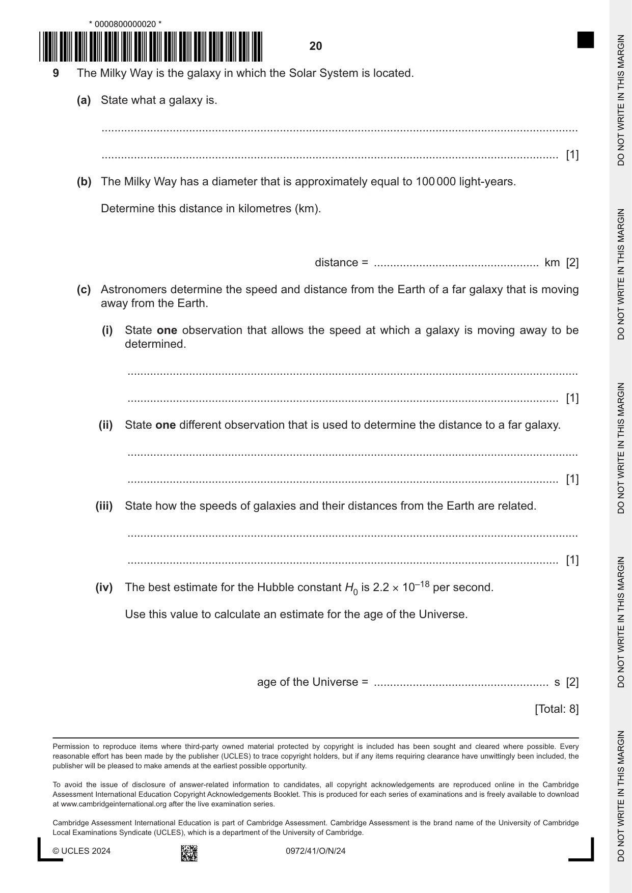
9 The Milky Way is the galaxy in which the Solar System is located. (a) State what a galaxy is. ................................................................................................................................................... ............................................................................................................................................. [1] (b) The Milky Way has a diameter that is approximately equal to 100 000 light-years. Determine this distance in kilometres (km). distance = ................................................... km [2] (c) Astronomers determine the speed and distance from the Earth of a far galaxy that is moving away from the Earth. (i) State one observation that allows the speed at which a galaxy is moving away to be determined. ........................................................................................................................................... ..................................................................................................................................... [1] (ii) State one different observation that is used to determine the distance to a far galaxy. ........................................................................................................................................... ..................................................................................................................................... [1] (iii) State how the speeds of galaxies and their distances from the Earth are related. ........................................................................................................................................... ..................................................................................................................................... [1] (iv) The best estimate for the Hubble constant H0 is 2.2 × 10⁻¹⁸ per second. Use this value to calculate an estimate for the age of the Universe. age of the Universe = ...................................................... s [2] [Total: 8]
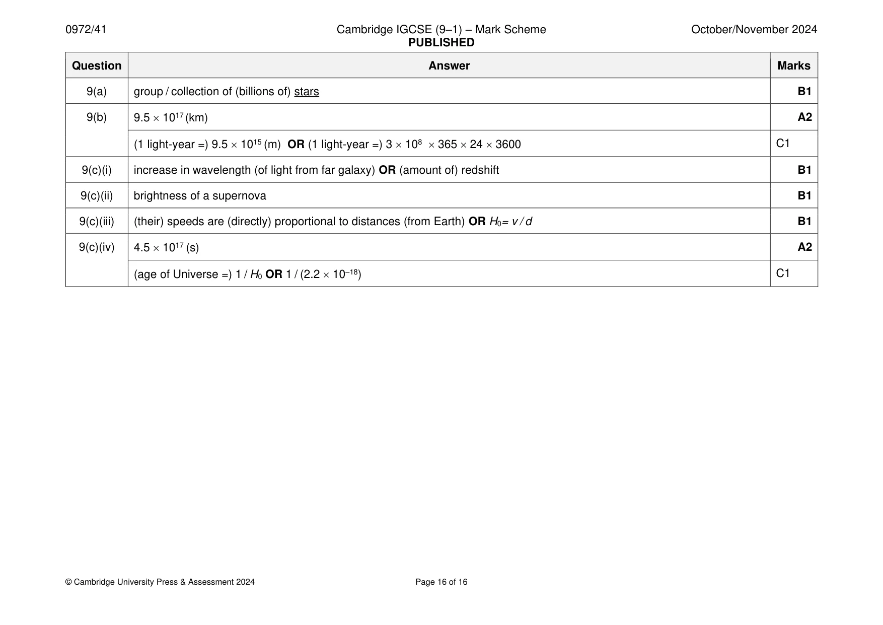
Mark scheme: 9(a) group / collection of (billions of) stars B1 9(b) 9.5 1017 (km) A2 (1 light-year =) 9.5 1015 (m) OR (1 light-year =) 3 108 365 24 3600 C1 9(c)(i) increase in wavelength (of light from far galaxy) OR (amount of) redshift B1 9(c)(ii) brightness of a supernova B1 9(c)(iii) (their) speeds are (directly) proportional to distances (from Earth) OR H0= v / d B1 9(c)(iv) 4.5 1017 (s) A2 (age of Universe =) 1 / H0 OR 1 / (2.2 10–18) C1
What was in this paper
The subtopics covered by these 9 questions, and how many questions each got. Open one in a new tab to see every Cambridge question on it.
What you needed in this session
Cambridge’s own grade thresholds for 2024 Oct/Nov, Paper 4 · Variant 1. A higher threshold means an easier paper — the bar moves with how the cohort did.