Cambridge IGCSE Physics 0625 — 2011 May/June Paper 6 · Variant 1
0625/61/M/J/11 · 40 marks · ≈45 min
The question paper and its mark scheme, free to read here and free to download. This is Cambridge’s own paper, exactly as it was sat.
Question paper12 pages
Mark scheme4 pages
Answers below. Sit the paper first if you are practising.
Paper as text
Question paper, page 1
This document consists of 10 printed pages and 2 blank pages. DC (LEO/SW) 28913/4 © UCLES 2011 [Turn over UNIVERSITY OF CAMBRIDGE INTERNATIONAL EXAMINATIONS International General Certificate of Secondary Education * 9 0 9 6 7 1 7 3 6 0 * PHYSICS 0625/61 Paper 6 Alternative to Practical May/June 2011 1 hour Candidates answer on the Question Paper. No Additional Materials are required. READ THESE INSTRUCTIONS FIRST Write your Centre number, candidate number and name on all the work you hand in. Write in dark blue or black pen. You may use a pencil for any diagrams, graphs or rough working. Do not use staples, paper clips, highlighters, glue or correction fluid. DO NOT WRITE IN ANY BARCODES. Answer all questions. At the end of the examination, fasten all your work securely together. The number of marks is given in brackets [ ] at the end of each question or part question. For Examiner’s Use 1 2 3 4 5 Total www.XtremePapers.com
Question paper, page 2
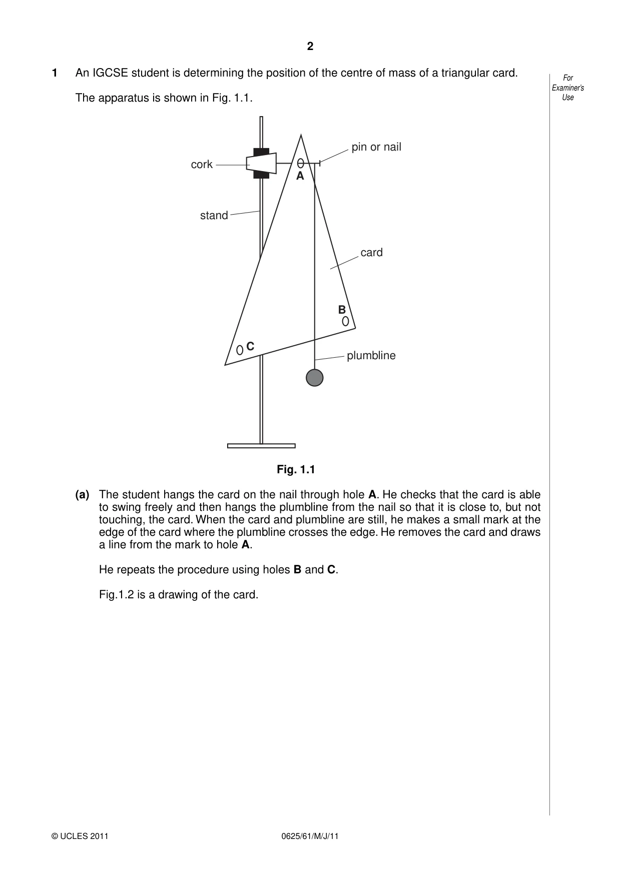
2 © UCLES 2011 0625/61/M/J/11 For Examiner’s Use 1 An IGCSE student is determining the position of the centre of mass of a triangular card. The apparatus is shown in Fig. 1.1. cork B A C pin or nail card plumbline stand Fig. 1.1 (a) The student hangs the card on the nail through hole A. He checks that the card is able to swing freely and then hangs the plumbline from the nail so that it is close to, but not touching, the card. When the card and plumbline are still, he makes a small mark at the edge of the card where the plumbline crosses the edge. He removes the card and draws a line from the mark to hole A. He repeats the procedure using holes B and C. Fig.1.2 is a drawing of the card.
Question paper, page 3
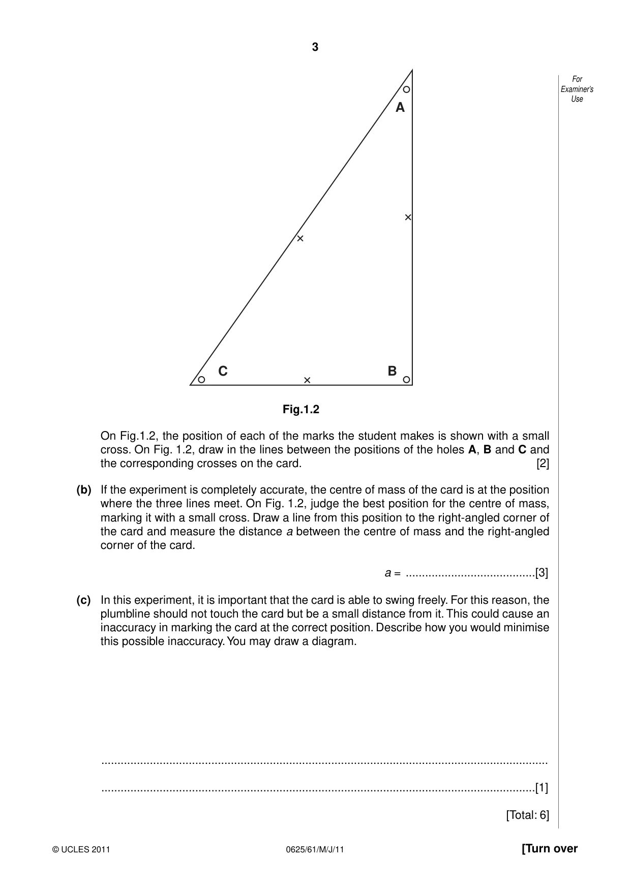
3 © UCLES 2011 [Turn over 0625/61/M/J/11 For Examiner’s Use C B A Fig.1.2 On Fig.1.2, the position of each of the marks the student makes is shown with a small cross. On Fig. 1.2, draw in the lines between the positions of the holes A, B and C and the corresponding crosses on the card. [2] (b) If the experiment is completely accurate, the centre of mass of the card is at the position where the three lines meet. On Fig. 1.2, judge the best position for the centre of mass, marking it with a small cross. Draw a line from this position to the right-angled corner of the card and measure the distance a between the centre of mass and the right-angled corner of the card. a = …[3] (c) In this experiment, it is important that the card is able to swing freely. For this reason, the plumbline should not touch the card but be a small distance from it. This could cause an inaccuracy in marking the card at the correct position. Describe how you would minimise this possible inaccuracy. You may draw a diagram. … …[1] [Total: 6]
Question paper, page 4
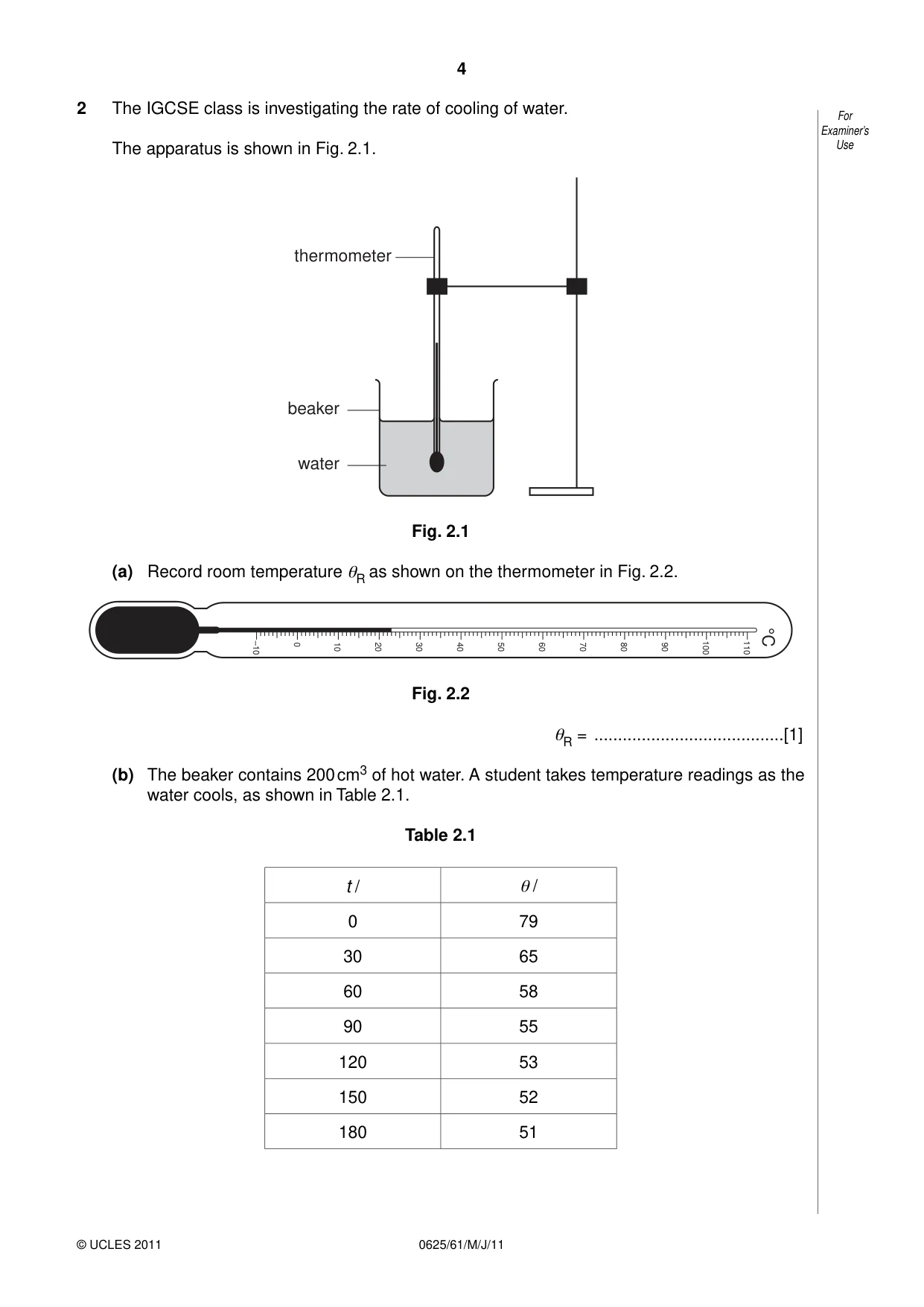
4 © UCLES 2011 0625/61/M/J/11 For Examiner’s Use 2 The IGCSE class is investigating the rate of cooling of water. The apparatus is shown in Fig. 2.1. thermometer beaker water Fig. 2.1 (a) Record room temperature θR as shown on the thermometer in Fig. 2.2. –10 0 10 20 30 40 50 60 70 80 90 100 110 °C Fig. 2.2 θR = …[1] (b) The beaker contains 200 cm3 of hot water. A student takes temperature readings as the water cools, as shown in Table 2.1. Table 2.1 t / θ / 0 79 30 65 60 58 90 55 120 53 150 52 180 51
Question paper, page 5
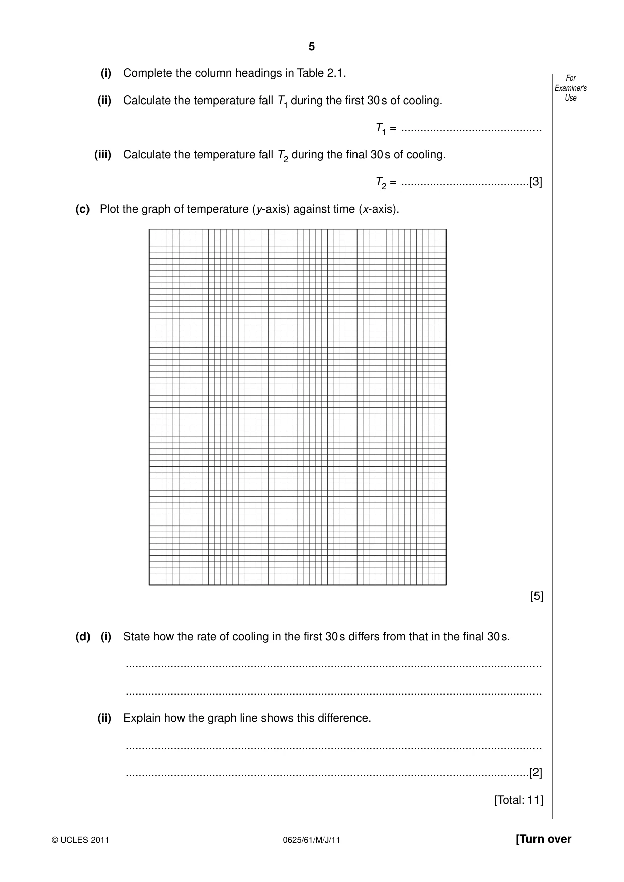
5 © UCLES 2011 [Turn over 0625/61/M/J/11 For Examiner’s Use (i) Complete the column headings in Table 2.1. (ii) Calculate the temperature fall T1 during the first 30 s of cooling. T1 = … (iii) Calculate the temperature fall T2 during the final 30 s of cooling. T2 = …[3] (c) Plot the graph of temperature (y-axis) against time (x-axis). [5] (d) (i) State how the rate of cooling in the first 30 s differs from that in the final 30 s. … … (ii) Explain how the graph line shows this difference. … …[2] [Total: 11]
Question paper, page 6
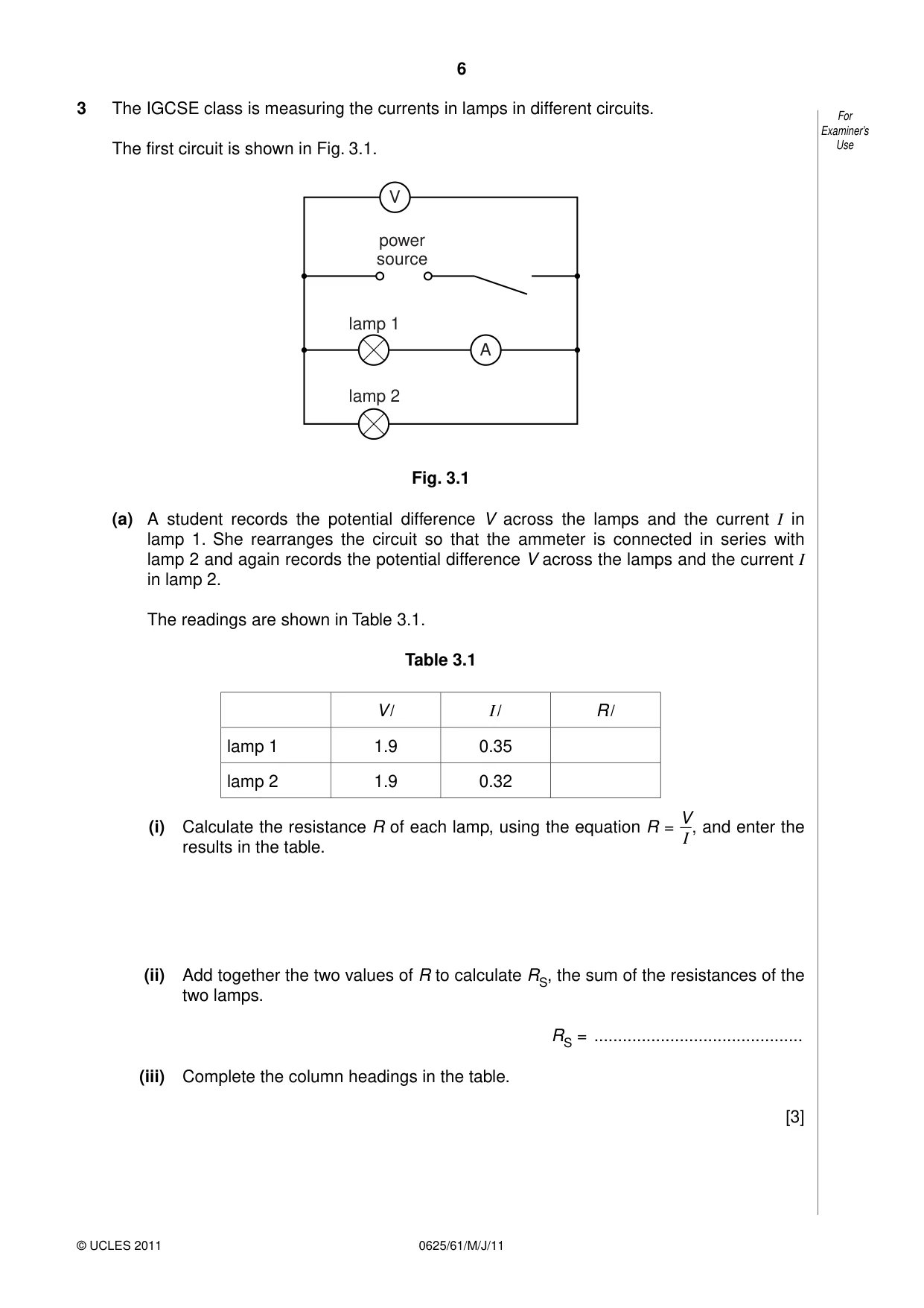
6 © UCLES 2011 0625/61/M/J/11 For Examiner’s Use 3 The IGCSE class is measuring the currents in lamps in different circuits. The first circuit is shown in Fig. 3.1. A V power source lamp 1 lamp 2 Fig. 3.1 (a) A student records the potential difference V across the lamps and the current I in lamp 1. She rearranges the circuit so that the ammeter is connected in series with lamp 2 and again records the potential difference V across the lamps and the current I in lamp 2. The readings are shown in Table 3.1. Table 3.1 V / I / R / lamp 1 1.9 0.35 lamp 2 1.9 0.32 (i) Calculate the resistance R of each lamp, using the equation R = V I , and enter the results in the table. (ii) Add together the two values of R to calculate RS, the sum of the resistances of the two lamps. RS = … (iii) Complete the column headings in the table. [3]
Question paper, page 7
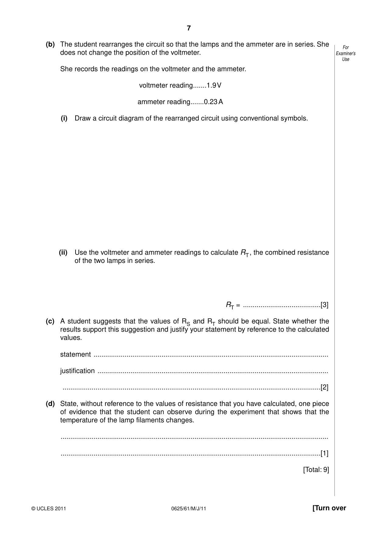
7 © UCLES 2011 [Turn over 0625/61/M/J/11 For Examiner’s Use (b) The student rearranges the circuit so that the lamps and the ammeter are in series. She does not change the position of the voltmeter. She records the readings on the voltmeter and the ammeter. voltmeter reading…1.9 V ammeter reading…0.23 A (i) Draw a circuit diagram of the rearranged circuit using conventional symbols. (ii) Use the voltmeter and ammeter readings to calculate RT , the combined resistance of the two lamps in series. RT = …[3] (c) A student suggests that the values of RS and RT should be equal. State whether the results support this suggestion and justify your statement by reference to the calculated values. statement … justification … …[2] (d) State, without reference to the values of resistance that you have calculated, one piece of evidence that the student can observe during the experiment that shows that the temperature of the lamp filaments changes. … …[1] [Total: 9]
Question paper, page 8
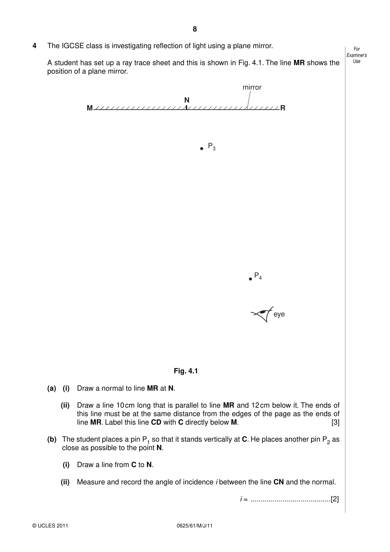
8 © UCLES 2011 0625/61/M/J/11 For Examiner’s Use 4 The IGCSE class is investigating reflection of light using a plane mirror. A student has set up a ray trace sheet and this is shown in Fig. 4.1. The line MR shows the position of a plane mirror. M R N P3 P4 eye mirror Fig. 4.1 (a) (i) Draw a normal to line MR at N. (ii) Draw a line 10 cm long that is parallel to line MR and 12 cm below it. The ends of this line must be at the same distance from the edges of the page as the ends of line MR. Label this line CD with C directly below M. [3] (b) The student places a pin P1 so that it stands vertically at C. He places another pin P2 as close as possible to the point N. (i) Draw a line from C to N. (ii) Measure and record the angle of incidence i between the line CN and the normal. i = …[2]
Question paper, page 9
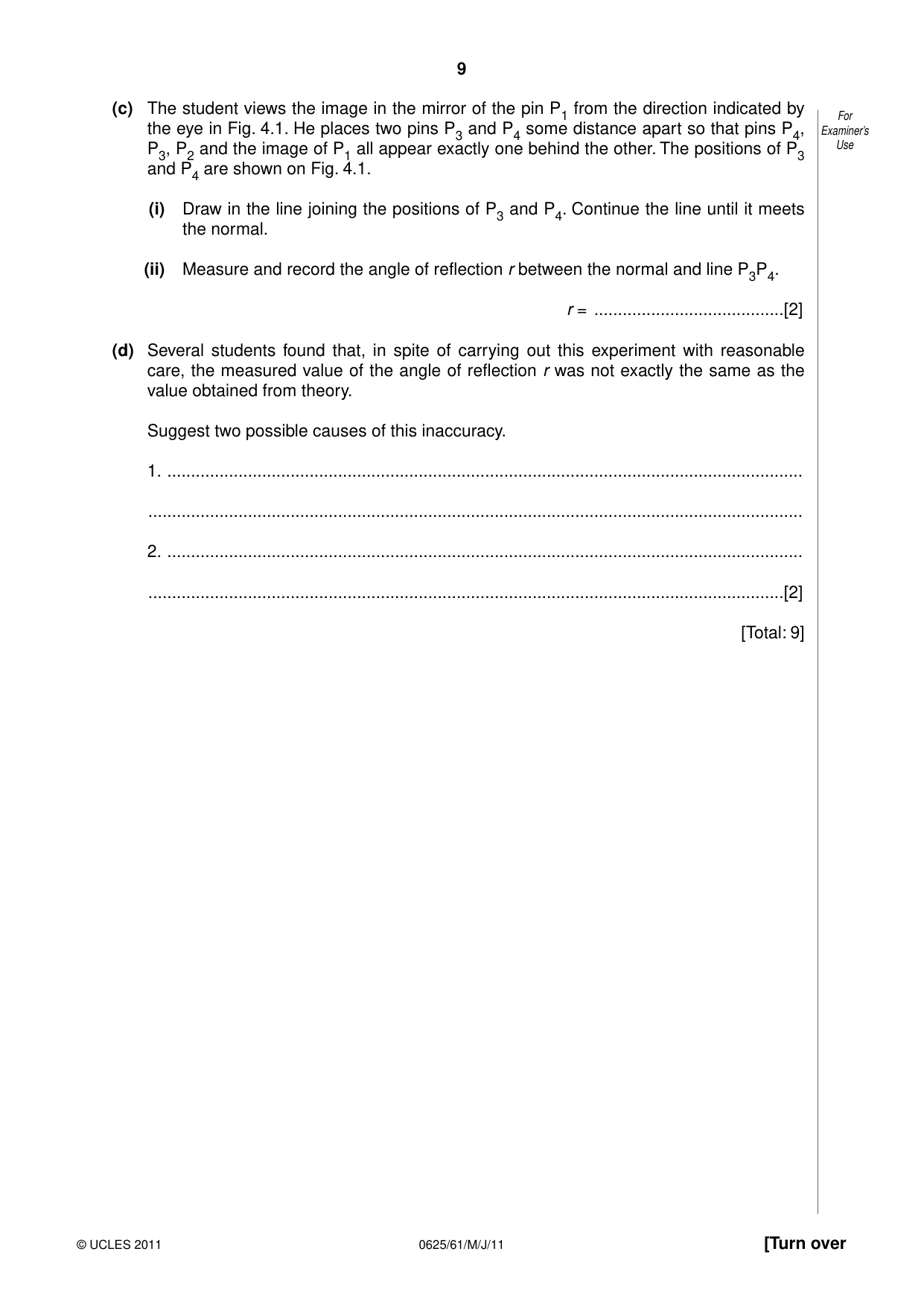
9 © UCLES 2011 [Turn over 0625/61/M/J/11 For Examiner’s Use (c) The student views the image in the mirror of the pin P1 from the direction indicated by the eye in Fig. 4.1. He places two pins P3 and P4 some distance apart so that pins P4, P3, P2 and the image of P1 all appear exactly one behind the other. The positions of P3 and P4 are shown on Fig. 4.1. (i) Draw in the line joining the positions of P3 and P4. Continue the line until it meets the normal. (ii) Measure and record the angle of reflection r between the normal and line P3P4. r = …[2] (d) Several students found that, in spite of carrying out this experiment with reasonable care, the measured value of the angle of reflection r was not exactly the same as the value obtained from theory. Suggest two possible causes of this inaccuracy. 1. … … 2. … …[2] [Total: 9]
Question paper, page 10
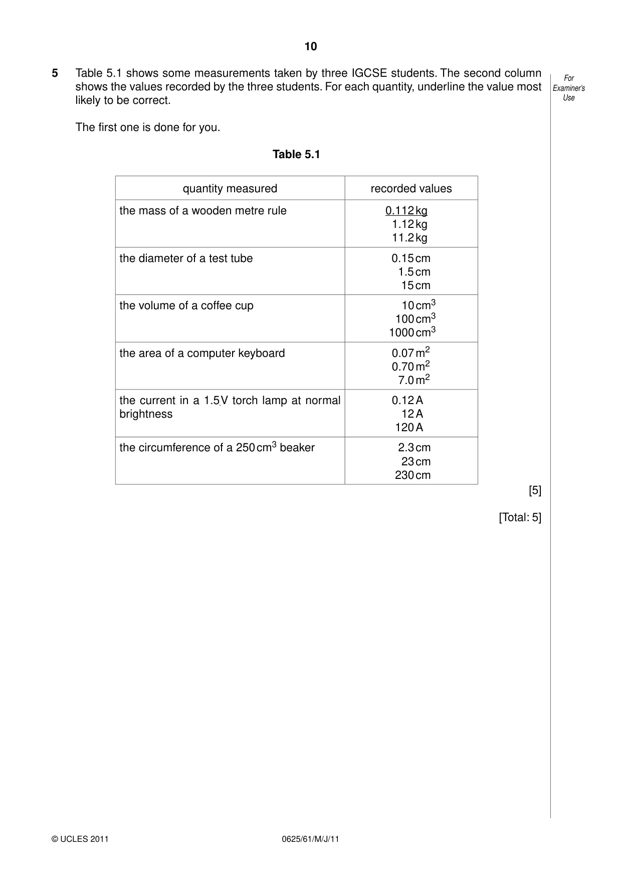
10 © UCLES 2011 0625/61/M/J/11 For Examiner’s Use 5 Table 5.1 shows some measurements taken by three IGCSE students. The second column shows the values recorded by the three students. For each quantity, underline the value most likely to be correct. The first one is done for you. Table 5.1 quantity measured recorded values the mass of a wooden metre rule 0.112 kg 1.12 kg 11.2 kg the diameter of a test tube 0.15 cm 1.5 cm 15 cm the volume of a coffee cup 10 cm3 100 cm3 1000 cm3 the area of a computer keyboard 0.07 m2 0.70 m2 7.0 m2 the current in a 1.5 V torch lamp at normal brightness 0.12 A 12 A 120 A the circumference of a 250 cm3 beaker 2.3 cm 23 cm 230 cm [5] [Total: 5]
Question paper, page 11
11 0625/61/M/J/11 © UCLES 2011 BLANK PAGE
Question paper, page 12
12 0625/61/M/J/11 © UCLES 2011 BLANK PAGE Permission to reproduce items where third-party owned material protected by copyright is included has been sought and cleared where possible. Every reasonable effort has been made by the publisher (UCLES) to trace copyright holders, but if any items requiring clearance have unwittingly been included, the publisher will be pleased to make amends at the earliest possible opportunity. University of Cambridge International Examinations is part of the Cambridge Assessment Group. Cambridge Assessment is the brand name of University of Cambridge Local Examinations Syndicate (UCLES), which is itself a department of the University of Cambridge.
Mark scheme, page 1
UNIVERSITY OF CAMBRIDGE INTERNATIONAL EXAMINATIONS International General Certificate of Secondary Education MARK SCHEME for the May/June 2011 question paper for the guidance of teachers 0625 PHYSICS 0625/61 Paper 6 (Alternative to Practical), maximum raw mark 40 This mark scheme is published as an aid to teachers and candidates, to indicate the requirements of the examination. It shows the basis on which Examiners were instructed to award marks. It does not indicate the details of the discussions that took place at an Examiners’ meeting before marking began, which would have considered the acceptability of alternative answers. Mark schemes must be read in conjunction with the question papers and the report on the examination. • Cambridge will not enter into discussions or correspondence in connection with these mark schemes. Cambridge is publishing the mark schemes for the May/June 2011 question papers for most IGCSE, GCE Advanced Level and Advanced Subsidiary Level syllabuses and some Ordinary Level syllabuses. www.XtremePapers.com
Mark scheme, page 2
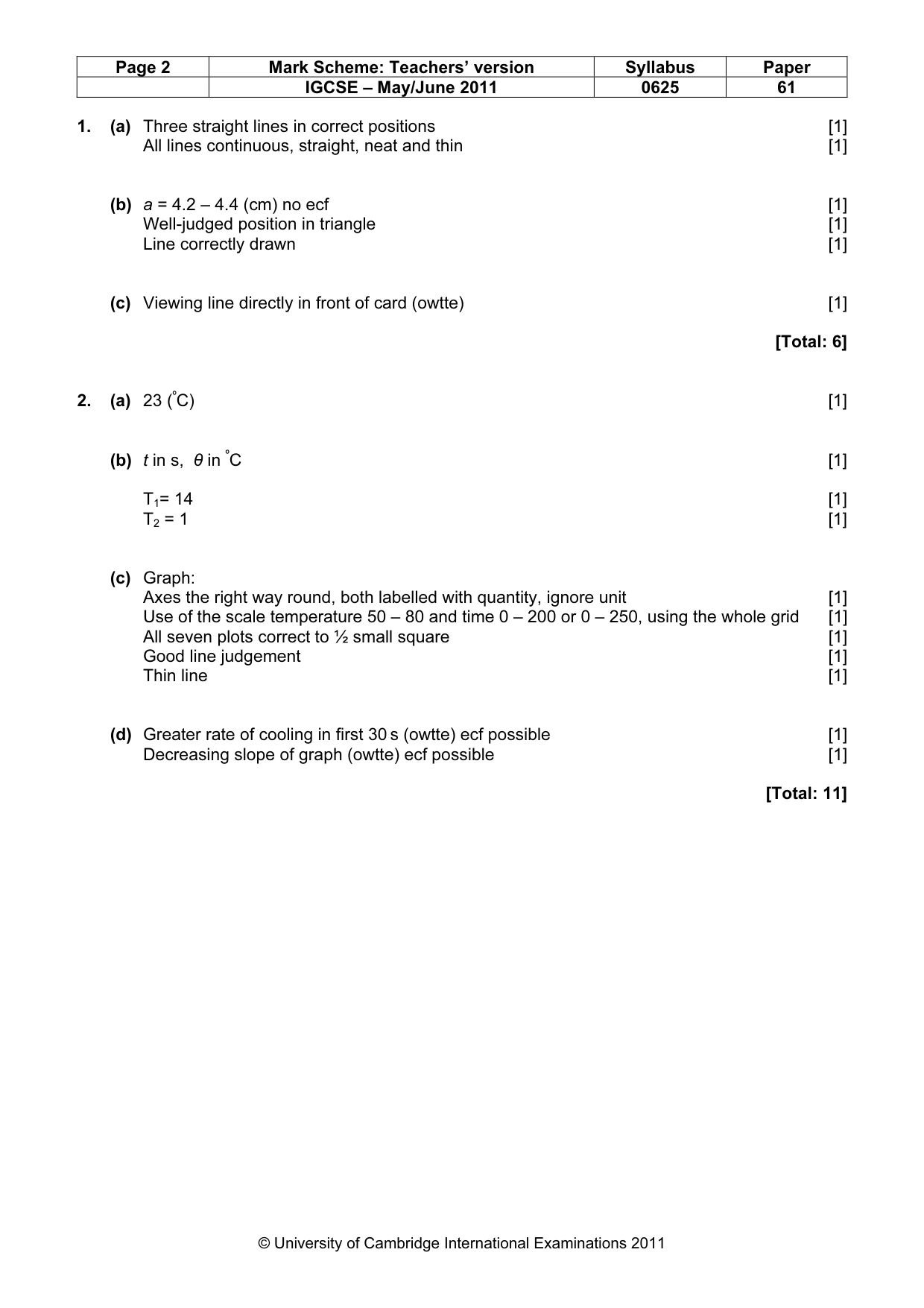
Page 2 Mark Scheme: Teachers’ version Syllabus Paper IGCSE – May/June 2011 0625 61 © University of Cambridge International Examinations 2011 1. (a) Three straight lines in correct positions [1] All lines continuous, straight, neat and thin [1] (b) a = 4.2 – 4.4 (cm) no ecf [1] Well-judged position in triangle [1] Line correctly drawn [1] (c) Viewing line directly in front of card (owtte) [1] [Total: 6] 2. (a) 23 (ºC) [1] (b) t in s, θ in ºC [1] T1= 14 [1] T2 = 1 [1] (c) Graph: Axes the right way round, both labelled with quantity, ignore unit [1] Use of the scale temperature 50 – 80 and time 0 – 200 or 0 – 250, using the whole grid [1] All seven plots correct to ½ small square [1] Good line judgement [1] Thin line [1] (d) Greater rate of cooling in first 30 s (owtte) ecf possible [1] Decreasing slope of graph (owtte) ecf possible [1] [Total: 11]
Mark scheme, page 3
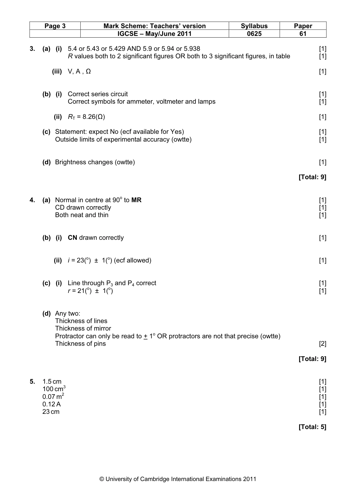
Page 3 Mark Scheme: Teachers’ version Syllabus Paper IGCSE – May/June 2011 0625 61 © University of Cambridge International Examinations 2011 3. (a) (i) 5.4 or 5.43 or 5.429 AND 5.9 or 5.94 or 5.938 [1] R values both to 2 significant figures OR both to 3 significant figures, in table [1] (iii) V, A , Ω [1] (b) (i) Correct series circuit [1] Correct symbols for ammeter, voltmeter and lamps [1] (ii) RT = 8.26(Ω) [1] (c) Statement: expect No (ecf available for Yes) [1] Outside limits of experimental accuracy (owtte) [1] (d) Brightness changes (owtte) [1] [Total: 9] 4. (a) Normal in centre at 90o to MR [1] CD drawn correctly [1] Both neat and thin [1] (b) (i) CN drawn correctly [1] (ii) i = 23(o) ± 1(o) (ecf allowed) [1] (c) (i) Line through P3 and P4 correct [1] r = 21(o) ± 1(o) [1] (d) Any two: Thickness of lines Thickness of mirror Protractor can only be read to + 1o OR protractors are not that precise (owtte) Thickness of pins [2] [Total: 9] 5. 1.5 cm [1] 100 cm3 [1] 0.07 m2 [1] 0.12 A [1] 23 cm [1] [Total: 5]
Mark scheme, page 4
Page 4 Mark Scheme: Teachers’ version Syllabus Paper IGCSE – May/June 2011 0625 61 © University of Cambridge International Examinations 2011 Abbreviations in the mark scheme: ecf = error carried forward. owtte = or words to that effect. c.a.o. = correct answer only
What you needed in this session
Cambridge’s own grade thresholds for 2011 May/June, Paper 6 · Variant 1. A higher threshold means an easier paper — the bar moves with how the cohort did.