Cambridge IGCSE Design and Technology 0445 — 2022 Oct/Nov Paper 4 · Variant 3
0445/43/O/N/22 · 12 questions · 50 marks · ≈56 min
The question paper and its mark scheme, free to read here and free to download. This is Cambridge’s own paper, exactly as it was sat.
Question paper20 pages



Mark scheme14 pages
Answers below. Sit the paper first if you are practising.
Questions as text
Q1 · Two methods of packaging drinks
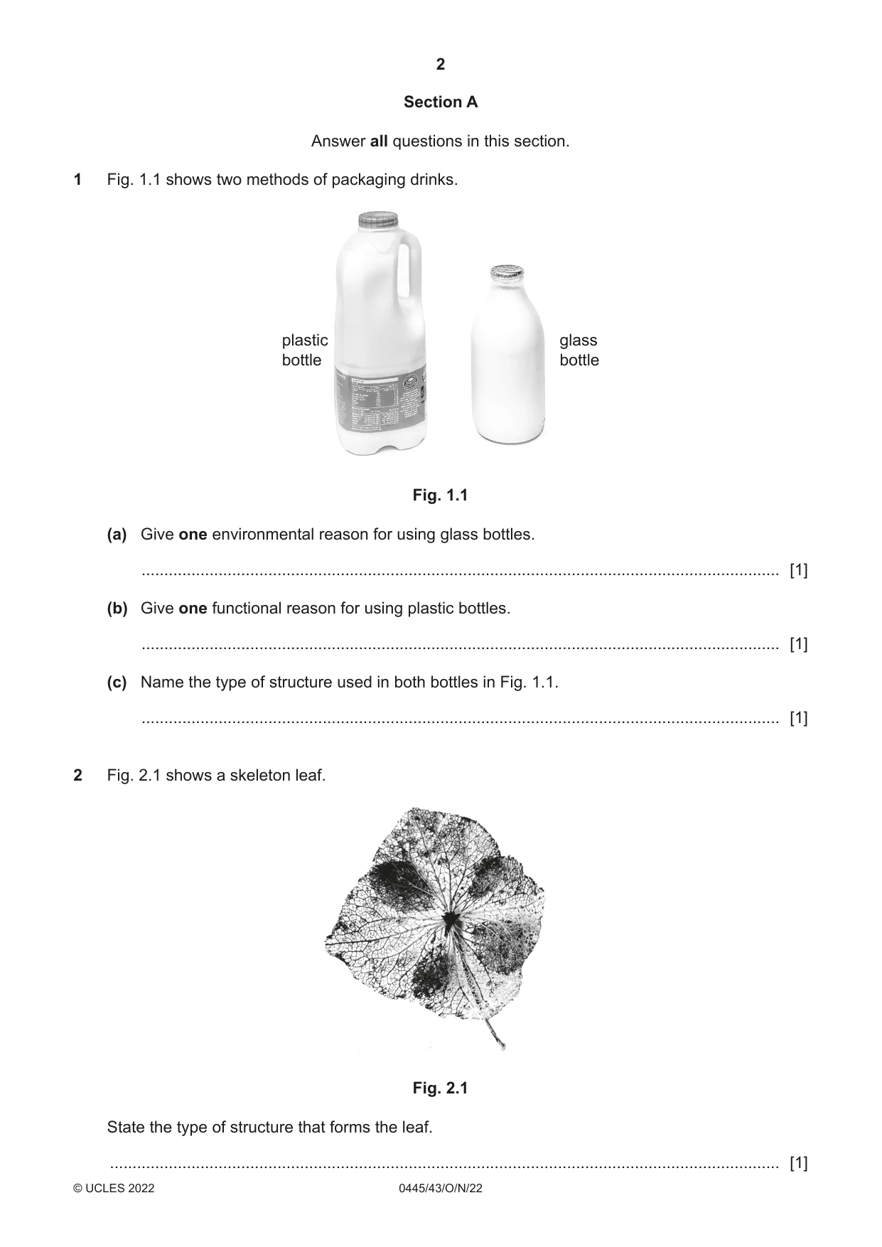
1 Fig. 1.1 shows two methods of packaging drinks. plastic glass bottle bottle Fig. 1.1 (a) Give one environmental reason for using glass bottles. ............................................................................................................................................. [1] (b) Give one functional reason for using plastic bottles. ............................................................................................................................................. [1] (c) Name the type of structure used in both bottles in Fig. 1.1. ............................................................................................................................................. [1]
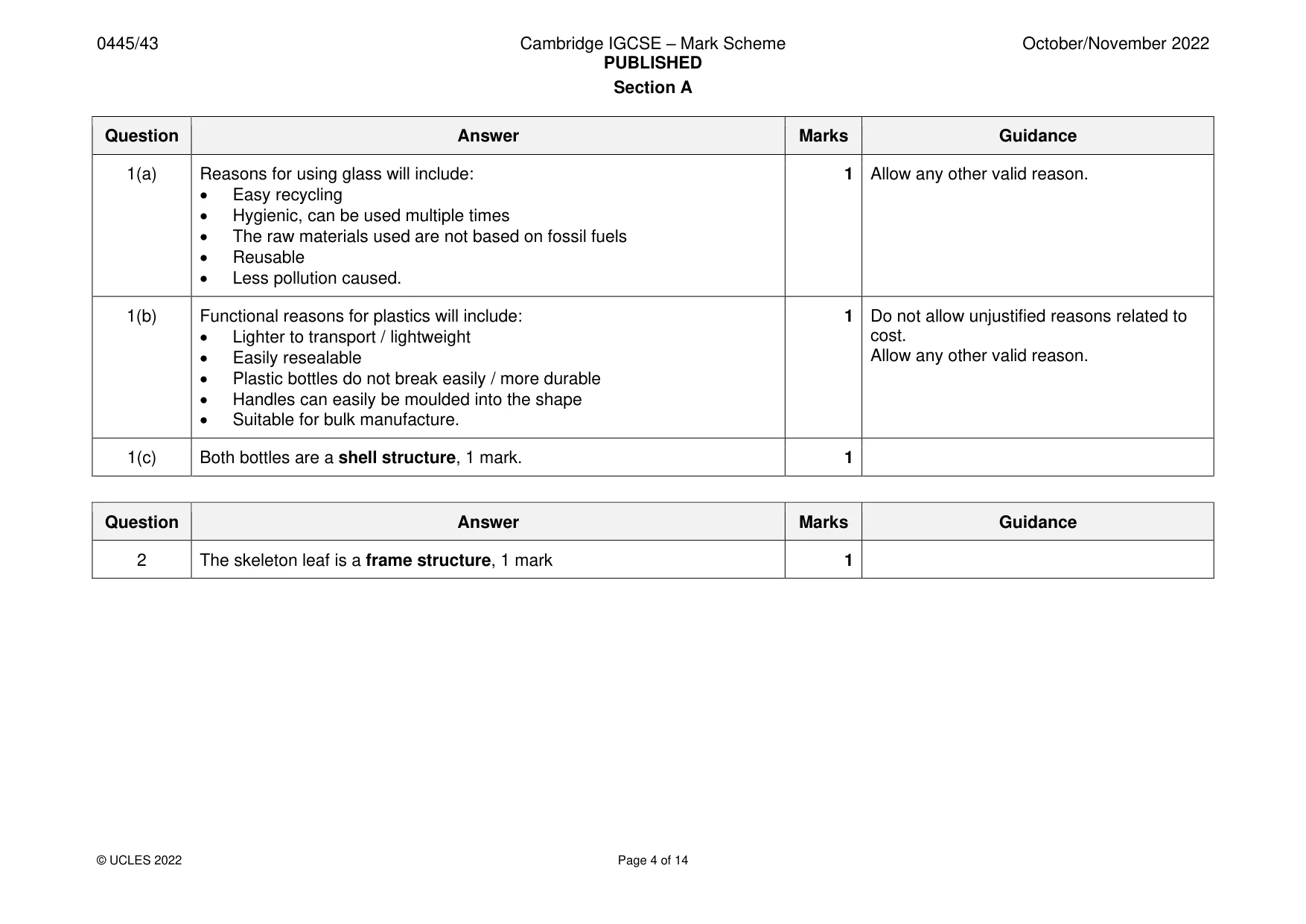
Mark scheme: Question Answer Marks Guidance 1(a) Reasons for using glass will include: 1 Allow any other valid reason. • Easy recycling • Hygienic, can be used multiple times • The raw materials used are not based on fossil fuels • Reusable • Less pollution caused. 1(b) Functional reasons for plastics will include: 1 Do not allow unjustified reasons related to • Lighter to transport / lightweight cost. • Easily resealable Allow any other valid reason. • Plastic bottles do not break easily / more durable • Handles can easily be moulded into the shape • Suitable for bulk manufacture. 1(c) Both bottles are a shell structure, 1 mark. 1
Question 2
2 Fig. 2.1 shows a skeleton leaf. Fig. 2.1 State the type of structure that forms the leaf. .................................................................................................................................................... [1]
Mark scheme: 2 The skeleton leaf is a frame structure, 1 mark 1
Q3 · Most electricity pylons are made from steel
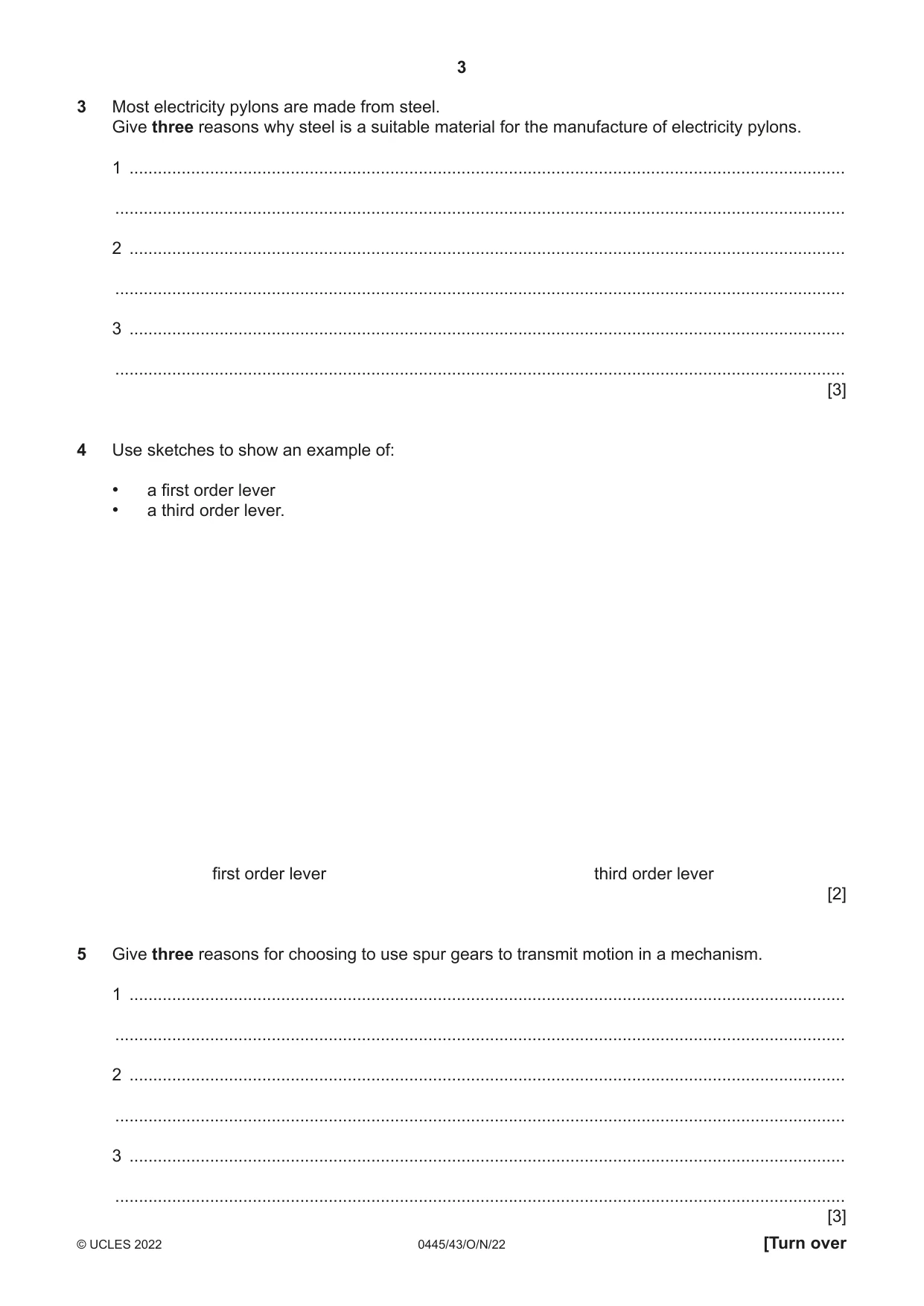
3 Most electricity pylons are made from steel. Give three reasons why steel is a suitable material for the manufacture of electricity pylons. 1 ....................................................................................................................................................... .......................................................................................................................................................... 2 ....................................................................................................................................................... .......................................................................................................................................................... 3 ....................................................................................................................................................... .......................................................................................................................................................... [3]
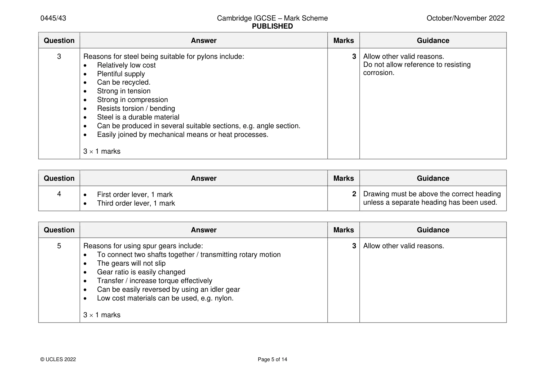
Mark scheme: 3 Reasons for steel being suitable for pylons include: 3 Allow other valid reasons. • Relatively low cost Do not allow reference to resisting • Plentiful supply corrosion. • Can be recycled. • Strong in tension • Strong in compression • Resists torsion / bending • Steel is a durable material • Can be produced in several suitable sections, e.g. angle section. • Easily joined by mechanical means or heat processes. 3 1 marks
Q4 · Use sketches to show an example of: • a first order lever • a third order lever
4 Use sketches to show an example of: • a first order lever • a third order lever. first order lever third order lever [2]
Mark scheme: 4 • First order lever, 1 mark 2 Drawing must be above the correct heading • Third order lever, 1 mark unless a separate heading has been used.
Q5 · Give three reasons for choosing to use spur gears to transmit motion in a mechanism
5 Give three reasons for choosing to use spur gears to transmit motion in a mechanism. 1 ....................................................................................................................................................... .......................................................................................................................................................... 2 ....................................................................................................................................................... .......................................................................................................................................................... 3 ....................................................................................................................................................... .......................................................................................................................................................... [3]
Mark scheme: 5 Reasons for using spur gears include: 3 Allow other valid reasons. • To connect two shafts together / transmitting rotary motion • The gears will not slip • Gear ratio is easily changed • Transfer / increase torque effectively • Can be easily reversed by using an idler gear • Low cost materials can be used, e.g. nylon. 3 1 marks
Q6 · A method of providing lubrication to a mechanism
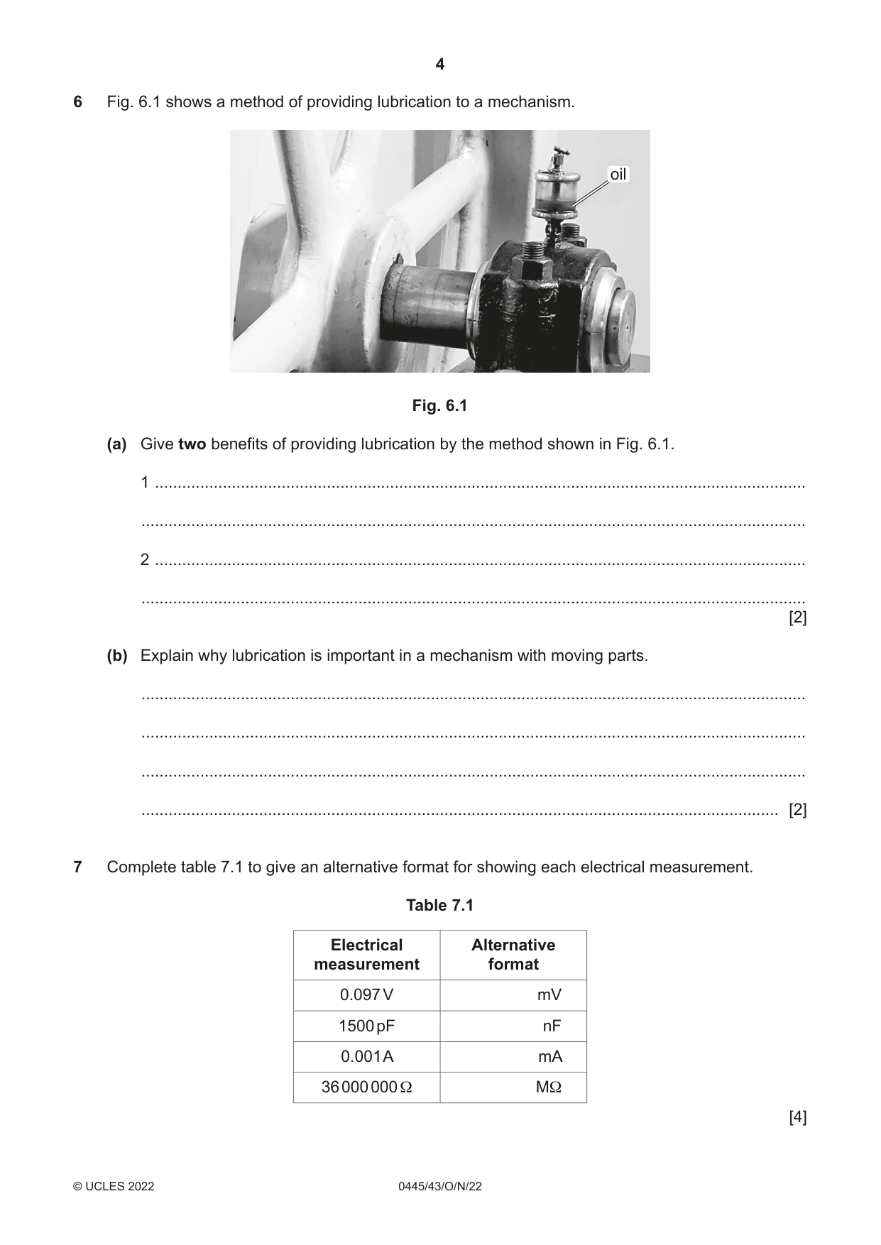
6 Fig. 6.1 shows a method of providing lubrication to a mechanism. oil Fig. 6.1 (a) Give two benefits of providing lubrication by the method shown in Fig. 6.1. 1 ................................................................................................................................................ ................................................................................................................................................... 2 ................................................................................................................................................ ................................................................................................................................................... [2] (b) Explain why lubrication is important in a mechanism with moving parts. ................................................................................................................................................... ................................................................................................................................................... ................................................................................................................................................... ............................................................................................................................................. [2]
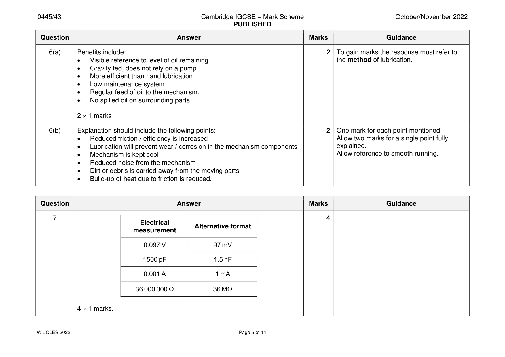
Mark scheme: 6(a) Benefits include: 2 To gain marks the response must refer to • Visible reference to level of oil remaining the method of lubrication. • Gravity fed, does not rely on a pump • More efficient than hand lubrication • Low maintenance system • Regular feed of oil to the mechanism. • No spilled oil on surrounding parts 2 1 marks 6(b) Explanation should include the following points: 2 One mark for each point mentioned. • Reduced friction / efficiency is increased Allow two marks for a single point fully • Lubrication will prevent wear / corrosion in the mechanism components explained. • Mechanism is kept cool Allow reference to smooth running. • Reduced noise from the mechanism • Dirt or debris is carried away from the moving parts • Build-up of heat due to friction is reduced.
Q7 · Complete table 7.1 to give an alternative format for showing each electrical measurement
7 Complete table 7.1 to give an alternative format for showing each electrical measurement. Table 7.1 Electrical Alternative measurement format 0.097 V mV 1500 pF nF 0.001 A mA 36 000 000 Ω MΩ [4]
Mark scheme: 7 4 Electrical Alternative format measurement 0.097 V 97 mV 1500 pF 1.5 nF 0.001 A 1 mA 36 000 000 36 M 4 1 marks.
Question 8
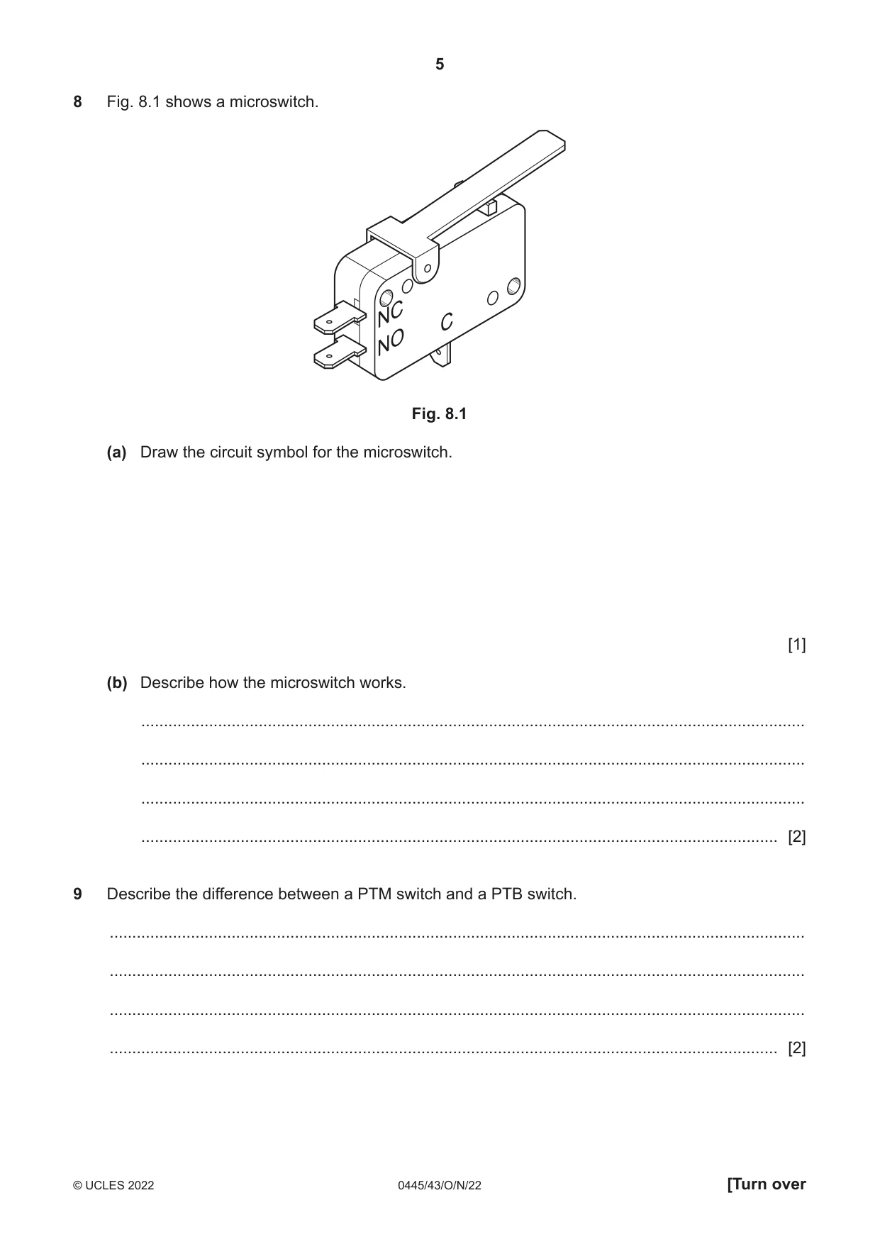
8 Fig. 8.1 shows a microswitch. NC C NO Fig. 8.1 (a) Draw the circuit symbol for the microswitch. [1] (b) Describe how the microswitch works. ................................................................................................................................................... ................................................................................................................................................... ................................................................................................................................................... ............................................................................................................................................. [2]
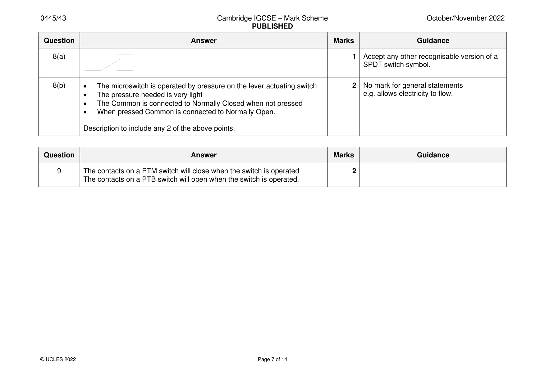
Mark scheme: 8(a) 1 Accept any other recognisable version of a SPDT switch symbol. 8(b) • The microswitch is operated by pressure on the lever actuating switch 2 No mark for general statements • The pressure needed is very light e.g. allows electricity to flow. • The Common is connected to Normally Closed when not pressed • When pressed Common is connected to Normally Open. Description to include any 2 of the above points.
Q9 · Describe the difference between a PTM switch and a PTB switch
9 Describe the difference between a PTM switch and a PTB switch. .......................................................................................................................................................... .......................................................................................................................................................... .......................................................................................................................................................... .................................................................................................................................................... [2]
Mark scheme: 9 The contacts on a PTM switch will close when the switch is operated 2 The contacts on a PTB switch will open when the switch is operated. Section B
Question 10
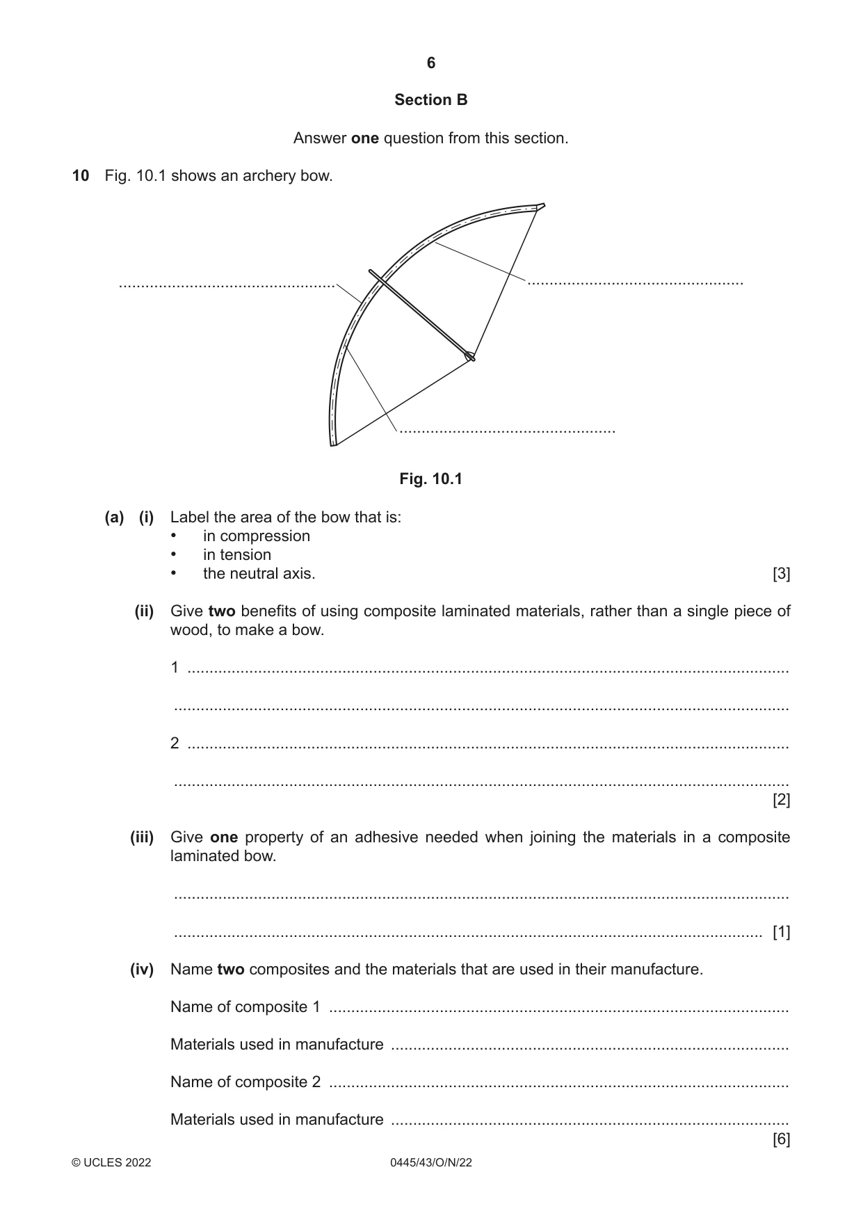
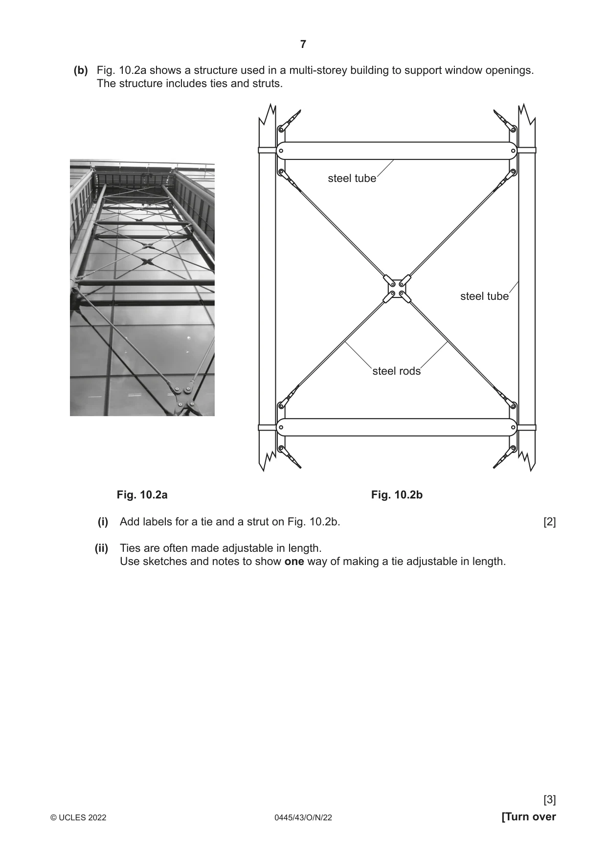
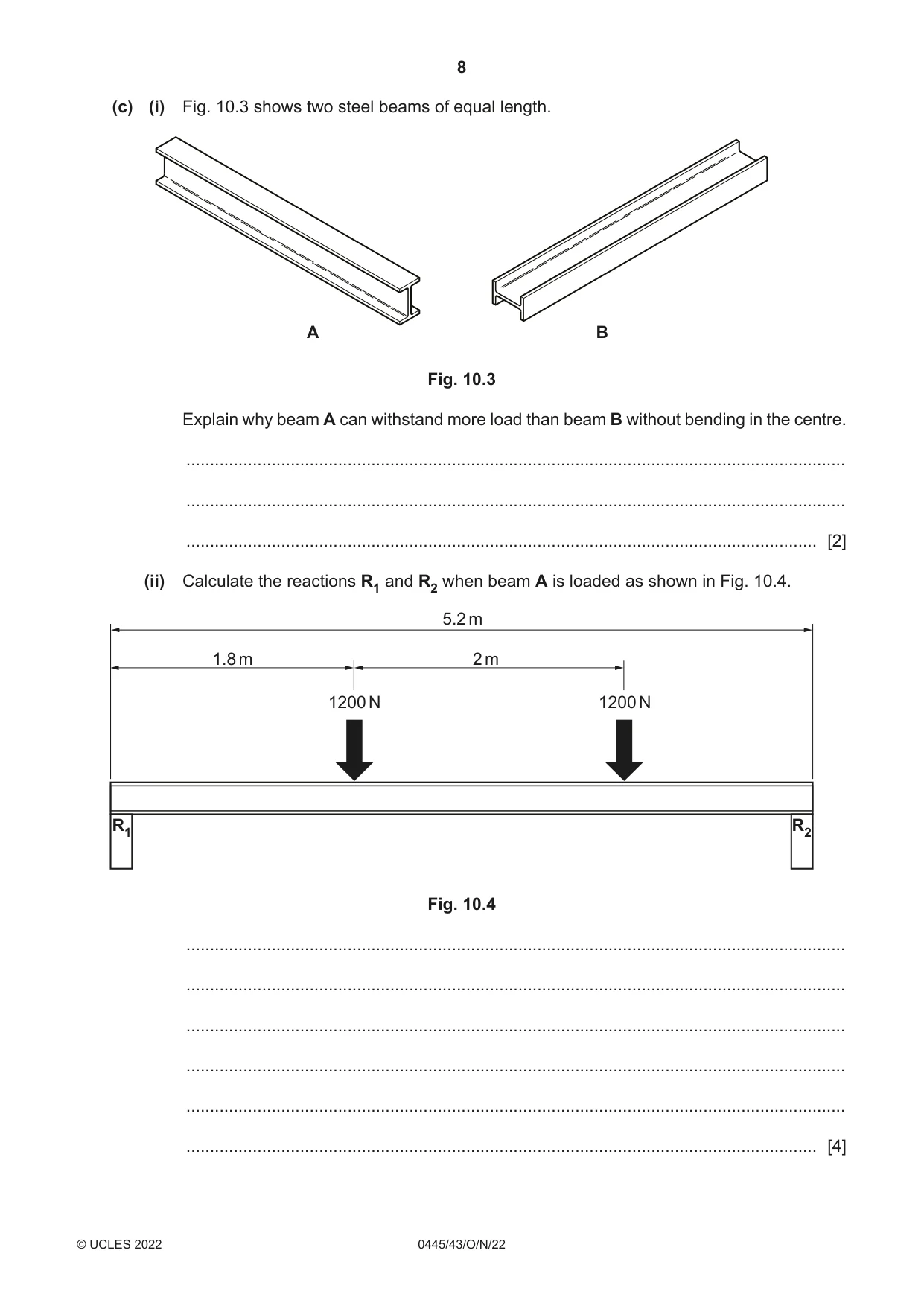
10 Fig. 10.1 shows an archery bow. ................................................. ................................................. ................................................. Fig. 10.1 (a) (i) Label the area of the bow that is: • in compression • in tension • the neutral axis. [3] (ii) Give two benefits of using composite laminated materials, rather than a single piece of wood, to make a bow. 1 ........................................................................................................................................ ........................................................................................................................................... 2 ........................................................................................................................................ ........................................................................................................................................... [2] (iii) Give one property of an adhesive needed when joining the materials in a composite laminated bow. ........................................................................................................................................... ..................................................................................................................................... [1] (iv) Name two composites and the materials that are used in their manufacture. Name of composite 1 ........................................................................................................ Materials used in manufacture .......................................................................................... Name of composite 2 ........................................................................................................ Materials used in manufacture .......................................................................................... [6] (b) Fig. 10.2a shows a structure used in a multi-storey building to support window openings. The structure includes ties and struts. steel tube steel tube steel rods Fig. 10.2a Fig. 10.2b (i) Add labels for a tie and a strut on Fig. 10.2b. [2] (ii) Ties are often made adjustable in length. Use sketches and notes to show one way of making a tie adjustable in length. [3] (c) (i) Fig. 10.3 shows two steel beams of equal length. A B Fig. 10.3 Explain why beam A can withstand more load than beam B without bending in the centre. ........................................................................................................................................... ........................................................................................................................................... ..................................................................................................................................... [2] (ii) Calculate the reactions R1 and R2 when beam A is loaded as shown in Fig. 10.4. 5.2 m 1.8 m 2 m 1200 N 1200 N R1 R2 Fig. 10.4 ........................................................................................................................................... ........................................................................................................................................... ........................................................................................................................................... ........................................................................................................................................... ........................................................................................................................................... ..................................................................................................................................... [4] (iii) Describe how Factor of Safety contributes to the design of a structure that uses beams. ........................................................................................................................................... ........................................................................................................................................... ..................................................................................................................................... [2]
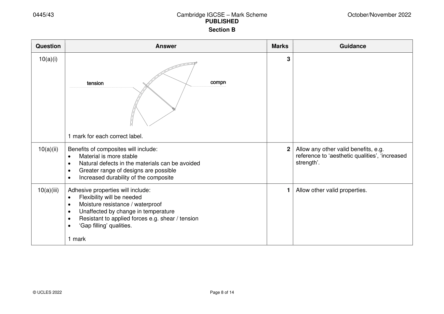
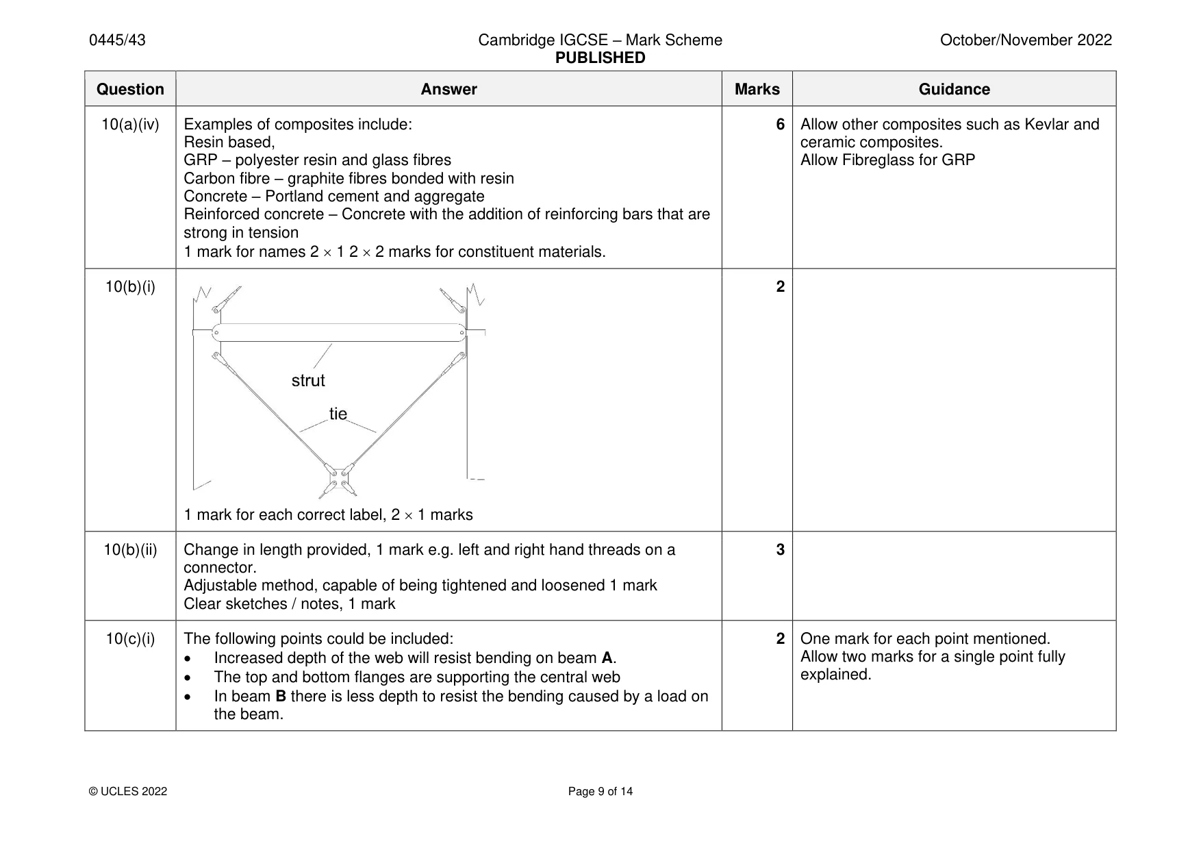
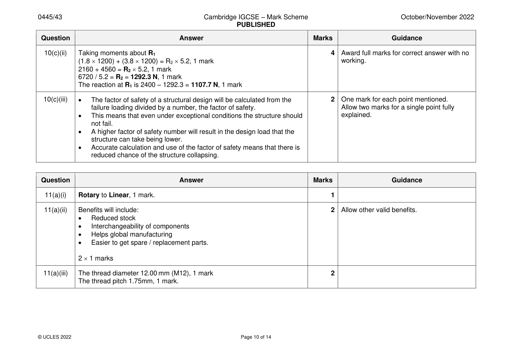
Mark scheme: 10(a)(i) 3 1 mark for each correct label. 10(a)(ii) Benefits of composites will include: 2 Allow any other valid benefits, e.g. • Material is more stable reference to ‘aesthetic qualities’, ‘increased • Natural defects in the materials can be avoided strength’. • Greater range of designs are possible • Increased durability of the composite 10(a)(iii) Adhesive properties will include: 1 Allow other valid properties. • Flexibility will be needed • Moisture resistance / waterproof • Unaffected by change in temperature • Resistant to applied forces e.g. shear / tension • ‘Gap filling’ qualities. 1 mark 10(a)(iv) Examples of composites include: 6 Allow other composites such as Kevlar and Resin based, ceramic composites. GRP – polyester resin and glass fibres Allow Fibreglass for GRP Carbon fibre – graphite fibres bonded with resin Concrete – Portland cement and aggregate Reinforced concrete – Concrete with the addition of reinforcing bars that are strong in tension 1 mark for names 2 1 2 2 marks for constituent materials. 10(b)(i) 2 1 mark for each correct label, 2 1 marks 10(b)(ii) Change in length provided, 1 mark e.g. left and right hand threads on a 3 connector. Adjustable method, capable of being tightened and loosened 1 mark Clear sketches / notes, 1 mark 10(c)(i) The following points could be included: 2 One mark for each point mentioned. • Increased depth of the web will resist bending on beam A. Allow two marks for a single point fully • The top and bottom flanges are supporting the central web explained. • In beam B there is less depth to resist the bending caused by a load on the beam. 10(c)(ii) Taking moments about R1 4 Award full marks for correct answer with no (1.8 1200) + (3.8 1200) = R2 5.2, 1 mark working. 2160 + 4560 = R2 5.2, 1 mark 6720 / 5.2 = R2 = 1292.3 N, 1 mark The reaction at R1 is 2400 – 1292.3 = 1107.7 N, 1 mark 10(c)(iii) • The factor of safety of a structural design will be calculated from the 2 One mark for each point mentioned. failure loading divided by a number, the factor of safety. Allow two marks for a single point fully • This means that even under exceptional conditions the structure should explained. not fail. • A higher factor of safety number will result in the design load that the structure can take being lower. • Accurate calculation and use of the factor of safety means that there is reduced chance of the structure collapsing.
Q11 · A bolt with a screw thread cut into it
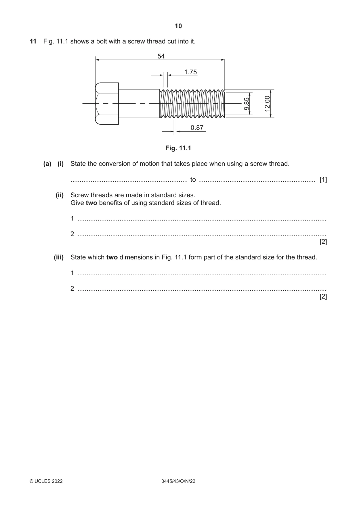
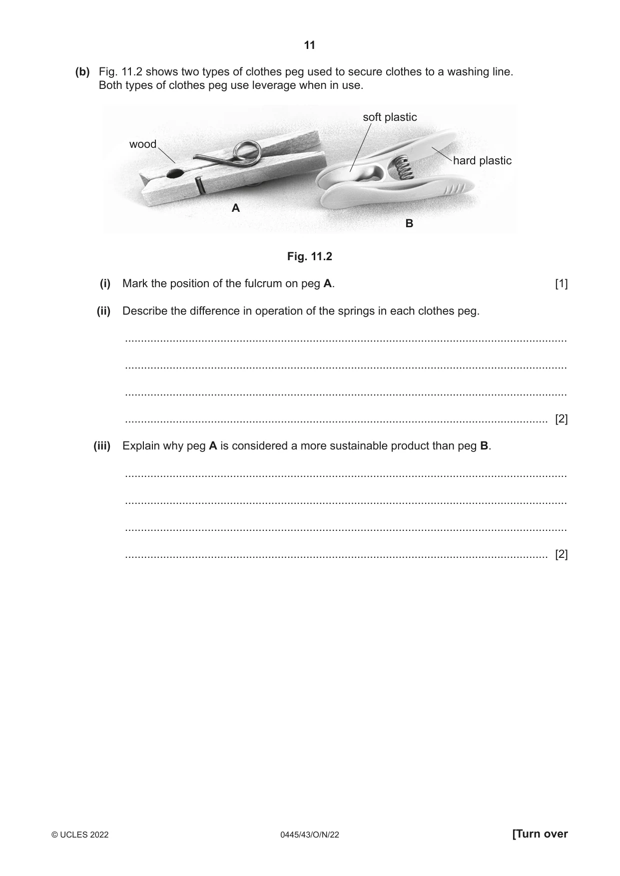
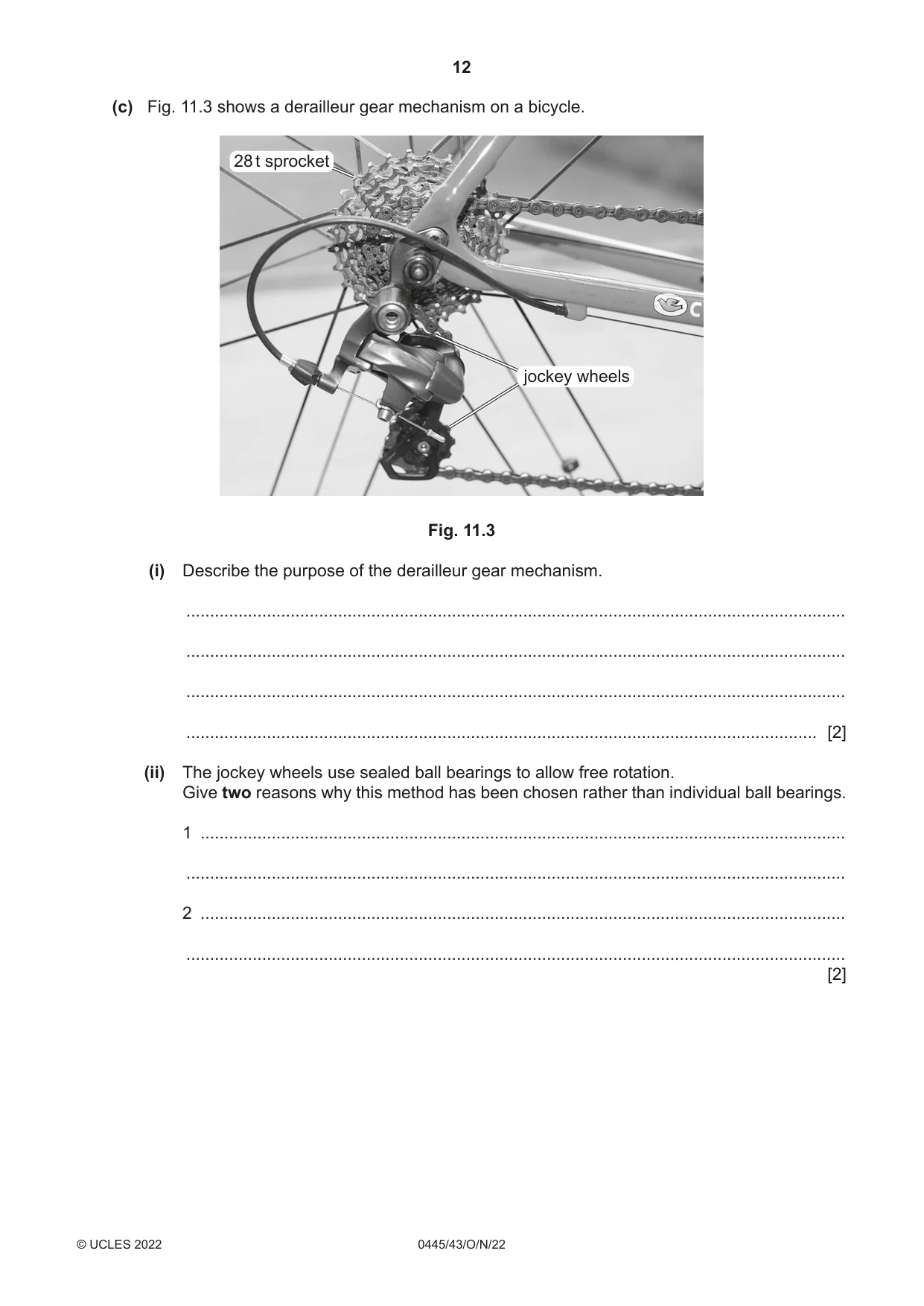
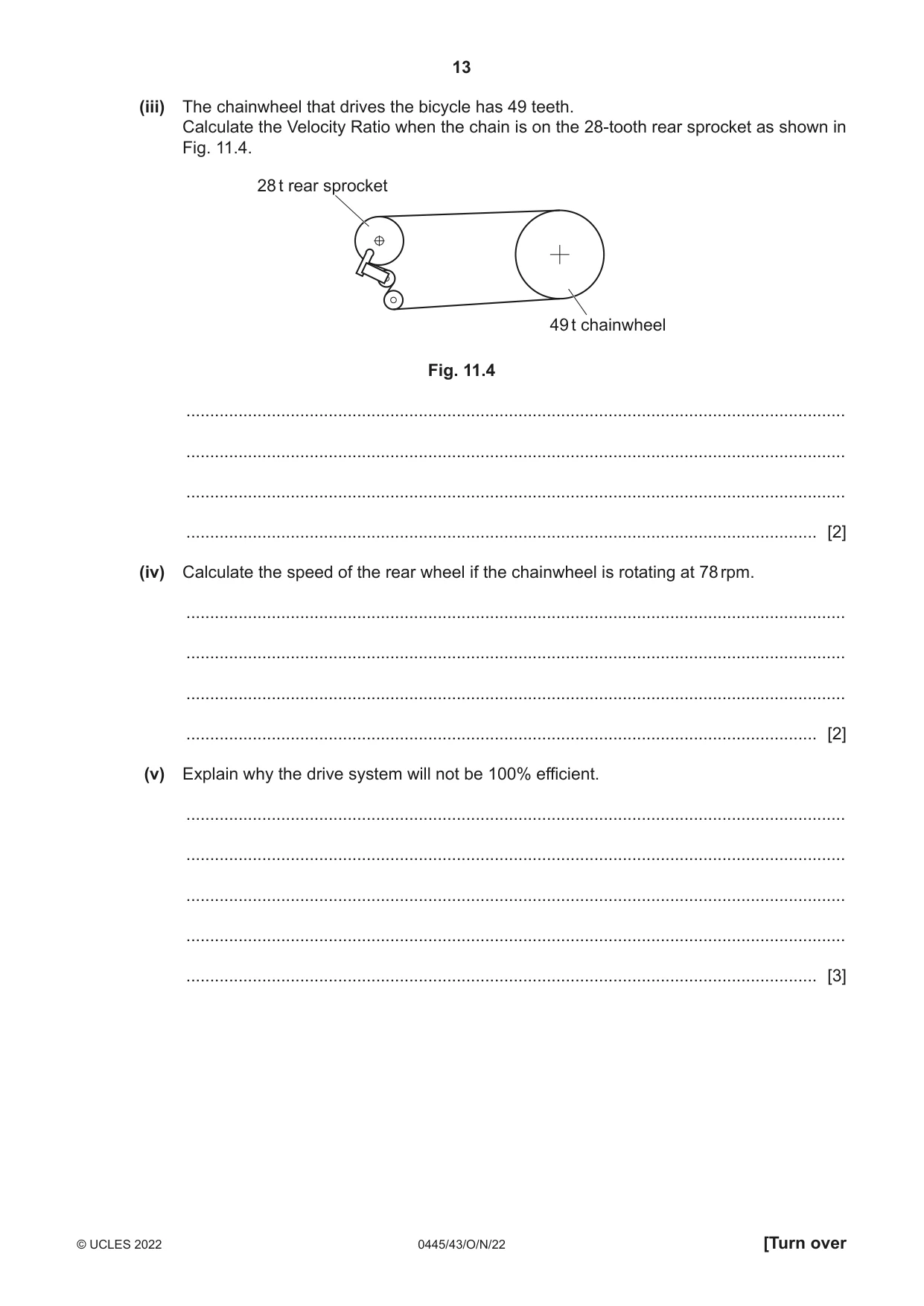
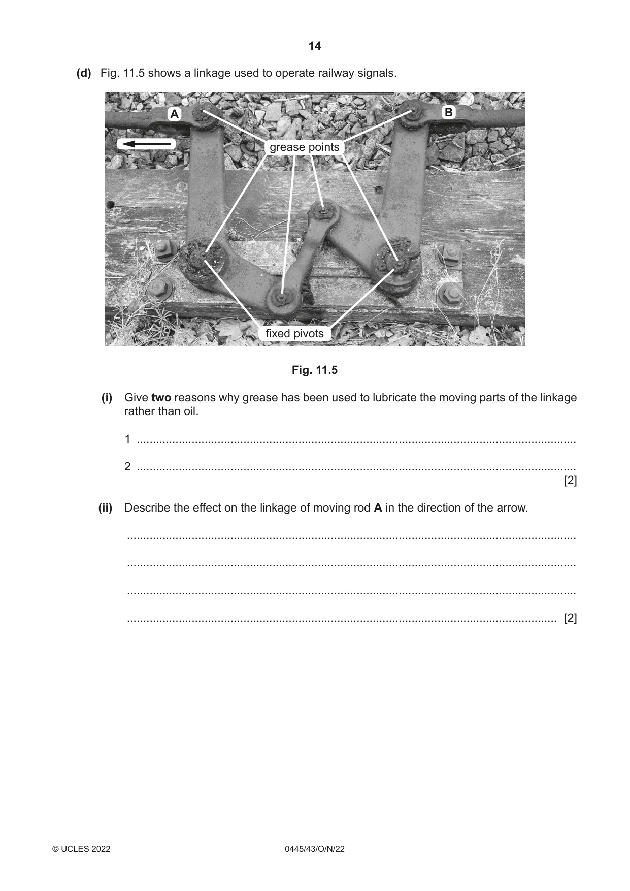
11 Fig. 11.1 shows a bolt with a screw thread cut into it. 54 1.75 9.85 12.00 0.87 Fig. 11.1 (a) (i) State the conversion of motion that takes place when using a screw thread. ................................................................ to ................................................................ [1] (ii) Screw threads are made in standard sizes. Give two benefits of using standard sizes of thread. 1 ........................................................................................................................................ 2 ........................................................................................................................................ [2] (iii) State which two dimensions in Fig. 11.1 form part of the standard size for the thread. 1 ........................................................................................................................................ 2 ........................................................................................................................................ [2] (b) Fig. 11.2 shows two types of clothes peg used to secure clothes to a washing line. Both types of clothes peg use leverage when in use. soft plastic wood hard plastic A B Fig. 11.2 (i) Mark the position of the fulcrum on peg A. [1] (ii) Describe the difference in operation of the springs in each clothes peg. ........................................................................................................................................... ........................................................................................................................................... ........................................................................................................................................... ..................................................................................................................................... [2] (iii) Explain why peg A is considered a more sustainable product than peg B. ........................................................................................................................................... ........................................................................................................................................... ........................................................................................................................................... ..................................................................................................................................... [2] (c) Fig. 11.3 shows a derailleur gear mechanism on a bicycle. 28 t sprocket jockey wheels Fig. 11.3 (i) Describe the purpose of the derailleur gear mechanism. ........................................................................................................................................... ........................................................................................................................................... ........................................................................................................................................... ..................................................................................................................................... [2] (ii) The jockey wheels use sealed ball bearings to allow free rotation. Give two reasons why this method has been chosen rather than individual ball bearings. 1 ........................................................................................................................................ ........................................................................................................................................... 2 ........................................................................................................................................ ........................................................................................................................................... [2] (iii) The chainwheel that drives the bicycle has 49 teeth. Calculate the Velocity Ratio when the chain is on the 28-tooth rear sprocket as shown in Fig. 11.4. 28 t rear sprocket 49 t chainwheel Fig. 11.4 ........................................................................................................................................... ........................................................................................................................................... ........................................................................................................................................... ..................................................................................................................................... [2] (iv) Calculate the speed of the rear wheel if the chainwheel is rotating at 78 rpm. ........................................................................................................................................... ........................................................................................................................................... ........................................................................................................................................... ..................................................................................................................................... [2] (v) Explain why the drive system will not be 100% efficient. ........................................................................................................................................... ........................................................................................................................................... ........................................................................................................................................... ........................................................................................................................................... ..................................................................................................................................... [3] (d) Fig. 11.5 shows a linkage used to operate railway signals. A B grease points fixed pivots Fig. 11.5 (i) Give two reasons why grease has been used to lubricate the moving parts of the linkage rather than oil. 1 ........................................................................................................................................ 2 ........................................................................................................................................ [2] (ii) Describe the effect on the linkage of moving rod A in the direction of the arrow. ........................................................................................................................................... ........................................................................................................................................... ........................................................................................................................................... ..................................................................................................................................... [2]
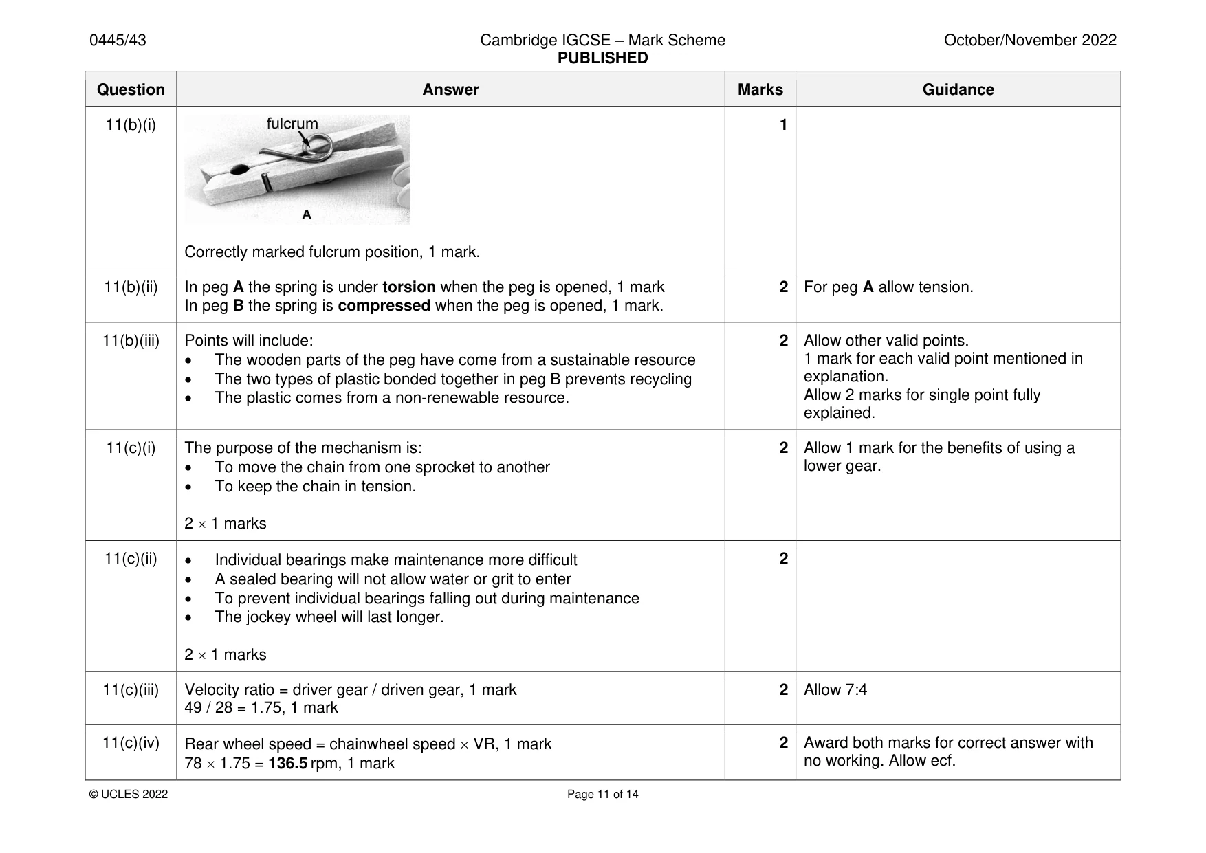
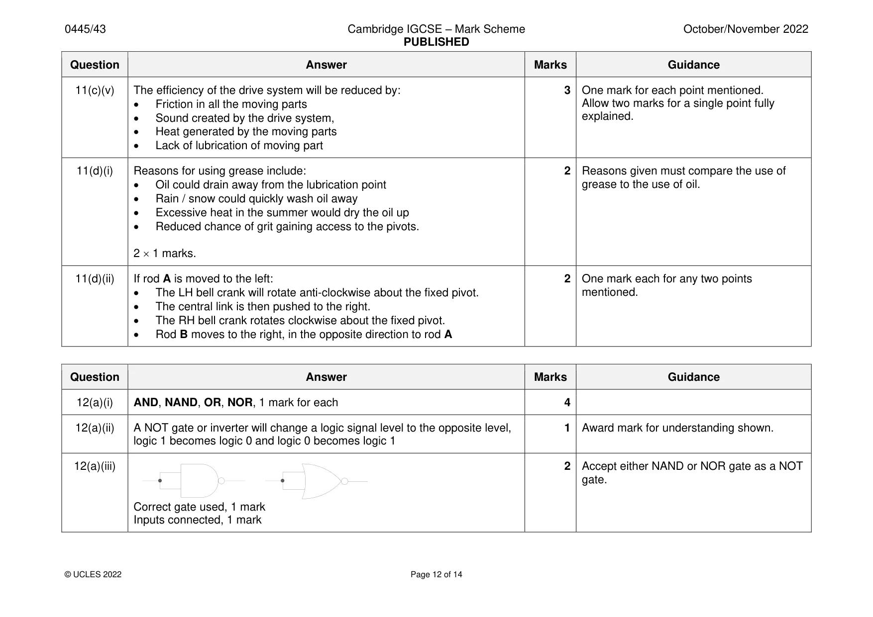
Mark scheme: 11(a)(i) Rotary to Linear, 1 mark. 1 11(a)(ii) Benefits will include: 2 Allow other valid benefits. • Reduced stock • Interchangeability of components • Helps global manufacturing • Easier to get spare / replacement parts. 2 1 marks 11(a)(iii) The thread diameter 12.00 mm (M12), 1 mark 2 The thread pitch 1.75mm, 1 mark. 11(b)(i) 1 Correctly marked fulcrum position, 1 mark. 11(b)(ii) In peg A the spring is under torsion when the peg is opened, 1 mark 2 For peg A allow tension. In peg B the spring is compressed when the peg is opened, 1 mark. 11(b)(iii) Points will include: 2 Allow other valid points. • The wooden parts of the peg have come from a sustainable resource 1 mark for each valid point mentioned in • The two types of plastic bonded together in peg B prevents recycling explanation. • The plastic comes from a non-renewable resource. Allow 2 marks for single point fully explained. 11(c)(i) The purpose of the mechanism is: 2 Allow 1 mark for the benefits of using a • To move the chain from one sprocket to another lower gear. • To keep the chain in tension. 2 1 marks 11(c)(ii) • Individual bearings make maintenance more difficult 2 • A sealed bearing will not allow water or grit to enter • To prevent individual bearings falling out during maintenance • The jockey wheel will last longer. 2 1 marks 11(c)(iii) Velocity ratio = driver gear / driven gear, 1 mark 2 Allow 7:4 49 / 28 = 1.75, 1 mark 11(c)(iv) Rear wheel speed = chainwheel speed VR, 1 mark 2 Award both marks for correct answer with 78 1.75 = 136.5 rpm, 1 mark no working. Allow ecf. 11(c)(v) The efficiency of the drive system will be reduced by: 3 One mark for each point mentioned. • Friction in all the moving parts Allow two marks for a single point fully • Sound created by the drive system, explained. • Heat generated by the moving parts • Lack of lubrication of moving part 11(d)(i) Reasons for using grease include: 2 Reasons given must compare the use of • Oil could drain away from the lubrication point grease to the use of oil. • Rain / snow could quickly wash oil away • Excessive heat in the summer would dry the oil up • Reduced chance of grit gaining access to the pivots. 2 1 marks. 11(d)(ii) If rod A is moved to the left: 2 One mark each for any two points • The LH bell crank will rotate anti-clockwise about the fixed pivot. mentioned. • The central link is then pushed to the right. • The RH bell crank rotates clockwise about the fixed pivot. • Rod B moves to the right, in the opposite direction to rod A
Q12 · Four logic gate symbols
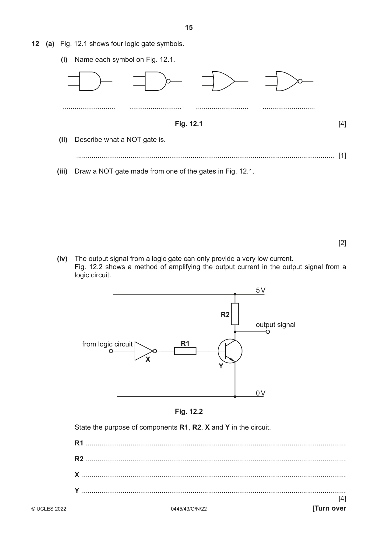
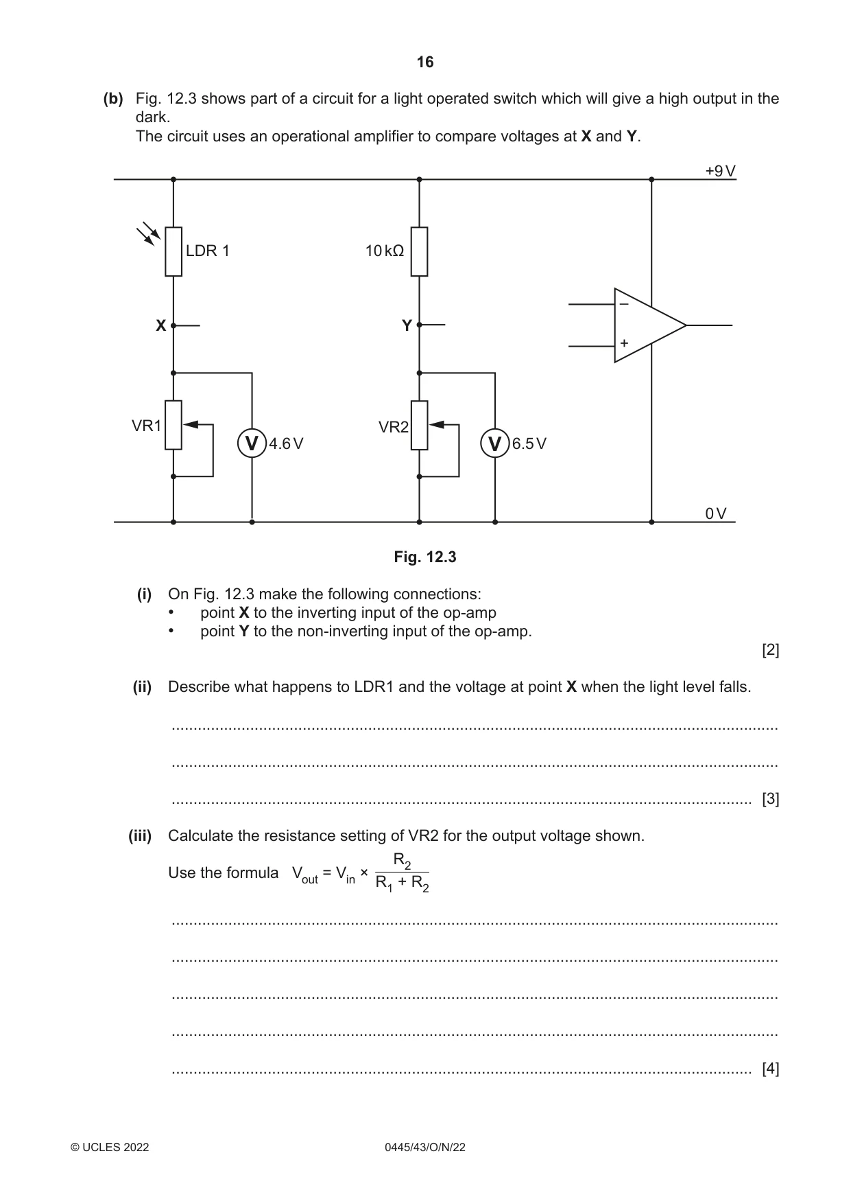
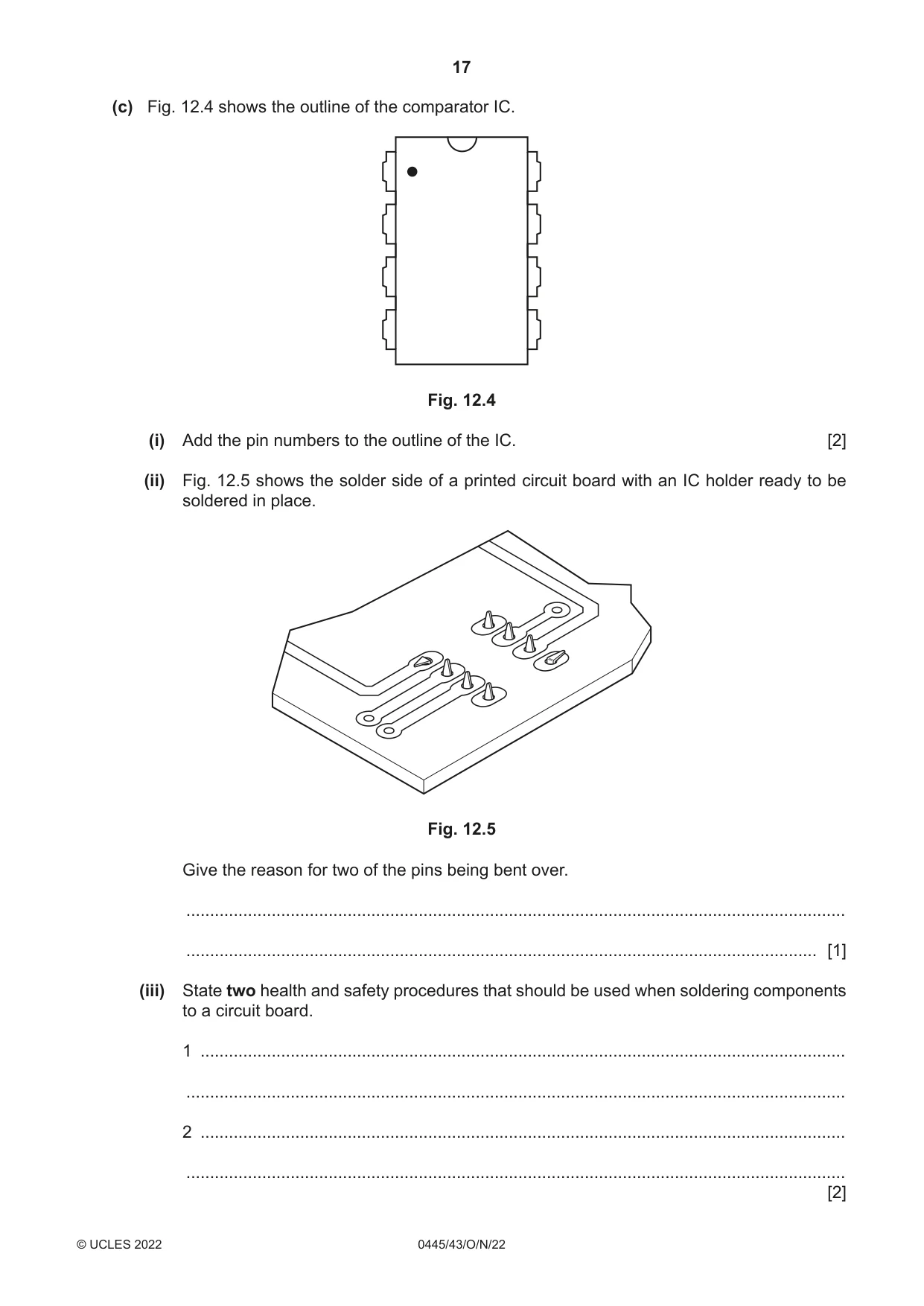
12 (a) Fig. 12.1 shows four logic gate symbols. (i) Name each symbol on Fig. 12.1. ........................... ........................... ........................... ........................... Fig. 12.1 [4] (ii) Describe what a NOT gate is. ..................................................................................................................................... [1] (iii) Draw a NOT gate made from one of the gates in Fig. 12.1. [2] (iv) The output signal from a logic gate can only provide a very low current. Fig. 12.2 shows a method of amplifying the output current in the output signal from a logic circuit. 5 V R2 output signal from logic circuit R1 X Y 0 V Fig. 12.2 State the purpose of components R1, R2, X and Y in the circuit. R1 ...................................................................................................................................... R2 ...................................................................................................................................... X ........................................................................................................................................ Y ........................................................................................................................................ [4] (b) Fig. 12.3 shows part of a circuit for a light operated switch which will give a high output in the dark. The circuit uses an operational amplifier to compare voltages at X and Y. +9 V LDR 1 10 kΩ – X Y + VR1 VR2 V 4.6 V V 6.5 V 0 V Fig. 12.3 (i) On Fig. 12.3 make the following connections: • point X to the inverting input of the op-amp • point Y to the non-inverting input of the op-amp. [2] (ii) Describe what happens to LDR1 and the voltage at point X when the light level falls. ........................................................................................................................................... ........................................................................................................................................... ..................................................................................................................................... [3] (iii) Calculate the resistance setting of VR2 for the output voltage shown. R2 Use the formula Vout = Vin × R1 + R2 ........................................................................................................................................... ........................................................................................................................................... ........................................................................................................................................... ........................................................................................................................................... ..................................................................................................................................... [4] (c) Fig. 12.4 shows the outline of the comparator IC. Fig. 12.4 (i) Add the pin numbers to the outline of the IC. [2] (ii) Fig. 12.5 shows the solder side of a printed circuit board with an IC holder ready to be soldered in place. Fig. 12.5 Give the reason for two of the pins being bent over. ........................................................................................................................................... ..................................................................................................................................... [1] (iii) State two health and safety procedures that should be used when soldering components to a circuit board. 1 ........................................................................................................................................ ........................................................................................................................................... 2 ........................................................................................................................................ ........................................................................................................................................... [2]
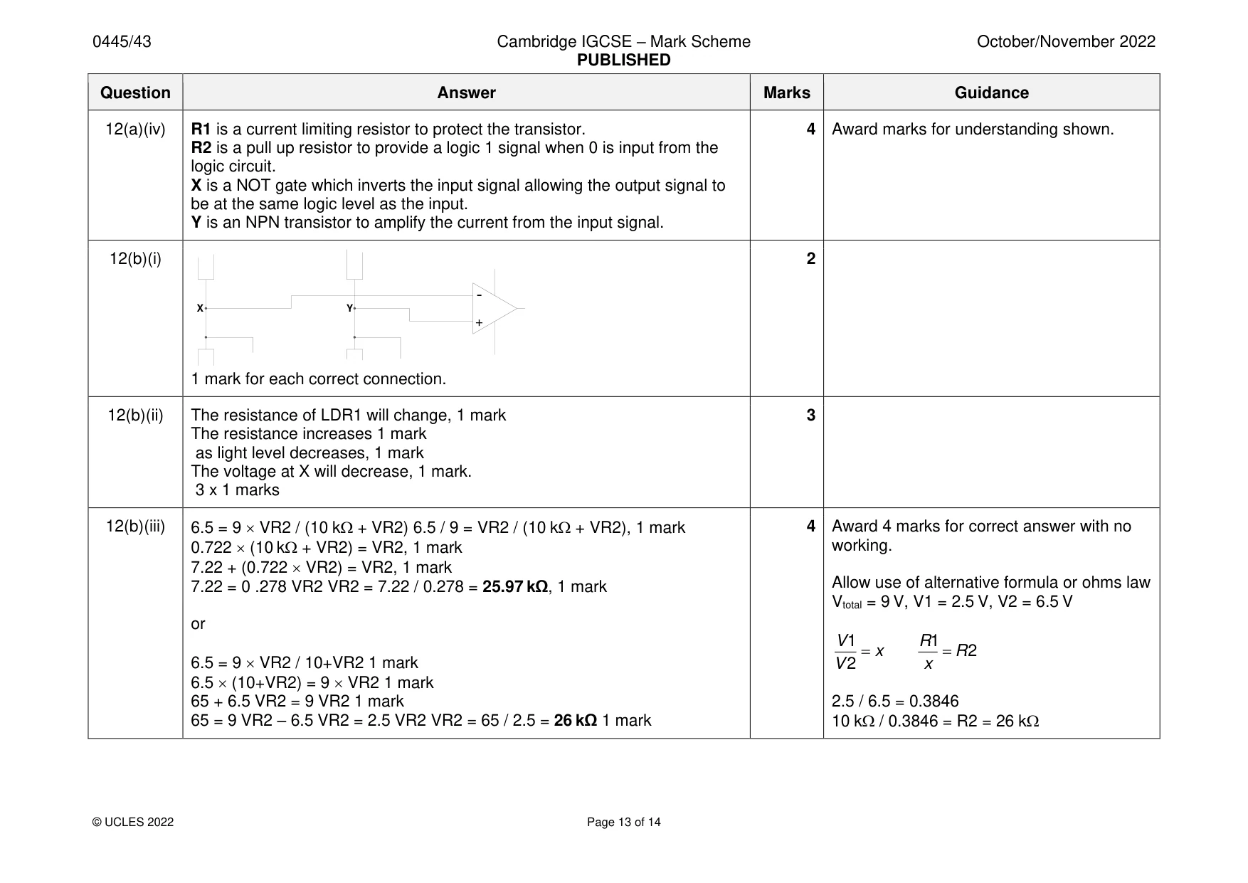
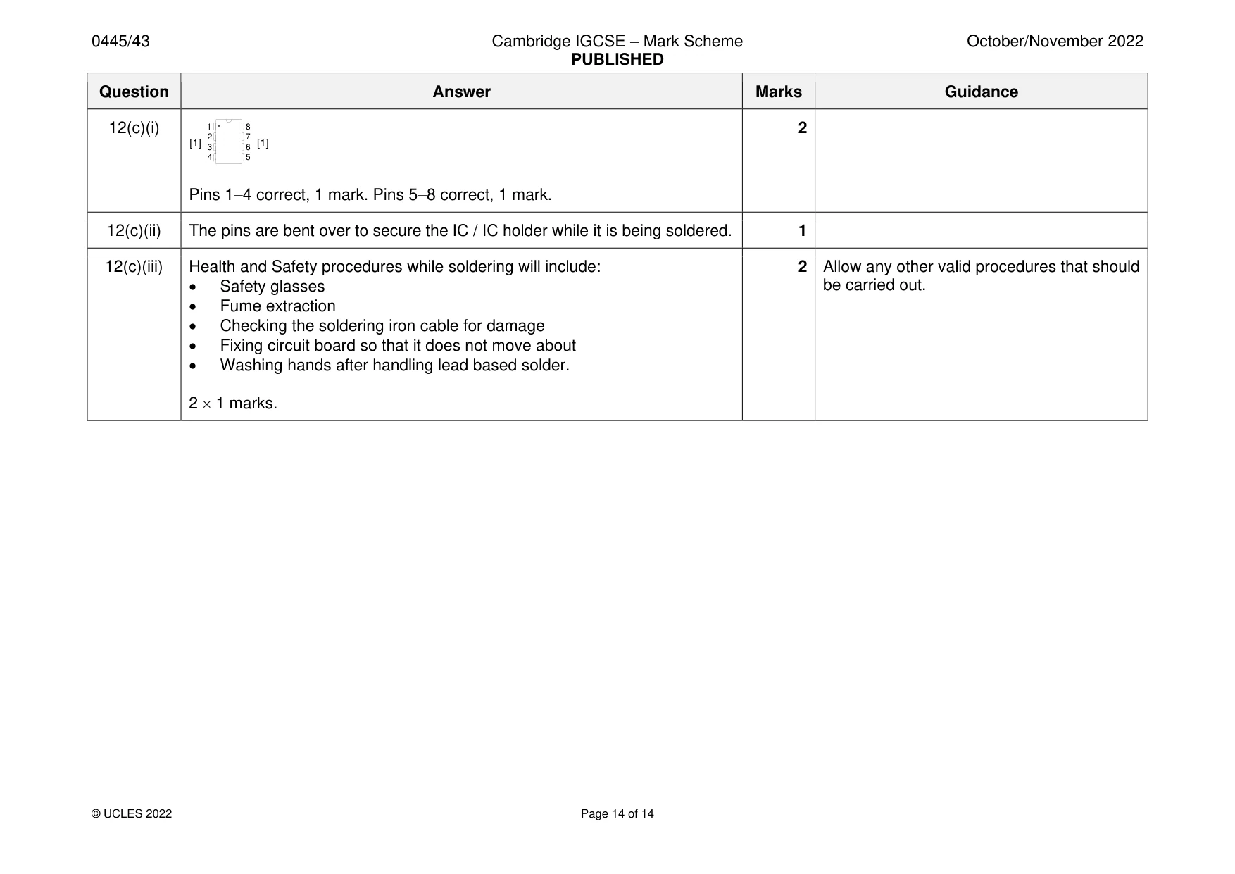
Mark scheme: 12(a)(i) AND, NAND, OR, NOR, 1 mark for each 4 12(a)(ii) A NOT gate or inverter will change a logic signal level to the opposite level, 1 Award mark for understanding shown. logic 1 becomes logic 0 and logic 0 becomes logic 1 12(a)(iii) 2 Accept either NAND or NOR gate as a NOT gate. Correct gate used, 1 mark Inputs connected, 1 mark 12(a)(iv) R1 is a current limiting resistor to protect the transistor. 4 Award marks for understanding shown. R2 is a pull up resistor to provide a logic 1 signal when 0 is input from the logic circuit. X is a NOT gate which inverts the input signal allowing the output signal to be at the same logic level as the input. Y is an NPN transistor to amplify the current from the input signal. 12(b)(i) 2 - X Y + 1 mark for each correct connection. 12(b)(ii) The resistance of LDR1 will change, 1 mark 3 The resistance increases 1 mark as light level decreases, 1 mark The voltage at X will decrease, 1 mark. 3 x 1 marks 12(b)(iii) 6.5 = 9 VR2 / (10 k + VR2) 6.5 / 9 = VR2 / (10 k + VR2), 1 mark 4 Award 4 marks for correct answer with no 0.722 (10 k + VR2) = VR2, 1 mark working. 7.22 + (0.722 VR2) = VR2, 1 mark 7.22 = 0 .278 VR2 VR2 = 7.22 / 0.278 = 25.97 kΩ, 1 mark Allow use of alternative formula or ohms law Vtotal = 9 V, V1 = 2.5 V, V2 = 6.5 V or V 1 R1 = x = R 2 6.5 = 9 VR2 / 10+VR2 1 mark V 2 x 6.5 (10+VR2) = 9 VR2 1 mark 65 + 6.5 VR2 = 9 VR2 1 mark 2.5 / 6.5 = 0.3846 65 = 9 VR2 – 6.5 VR2 = 2.5 VR2 VR2 = 65 / 2.5 = 26 kΩ 1 mark 10 k / 0.3846 = R2 = 26 k 12(c)(i) 1 8 2 2 7 [1] 3 6 [1] 4 5 Pins 1–4 correct, 1 mark. Pins 5–8 correct, 1 mark. 12(c)(ii) The pins are bent over to secure the IC / IC holder while it is being soldered. 1 12(c)(iii) Health and Safety procedures while soldering will include: 2 Allow any other valid procedures that should • Safety glasses be carried out. • Fume extraction • Checking the soldering iron cable for damage • Fixing circuit board so that it does not move about • Washing hands after handling lead based solder. 2 1 marks.
What was in this paper
The subtopics covered by these 12 questions, and how many questions each got. Open one in a new tab to see every Cambridge question on it.
What you needed in this session
Cambridge’s own grade thresholds for 2022 Oct/Nov, Paper 4 · Variant 3. A higher threshold means an easier paper — the bar moves with how the cohort did.