Cambridge IGCSE Design and Technology 0445 — 2021 Oct/Nov Paper 4 · Variant 2
0445/42/O/N/21 · 11 questions · 50 marks · ≈56 min
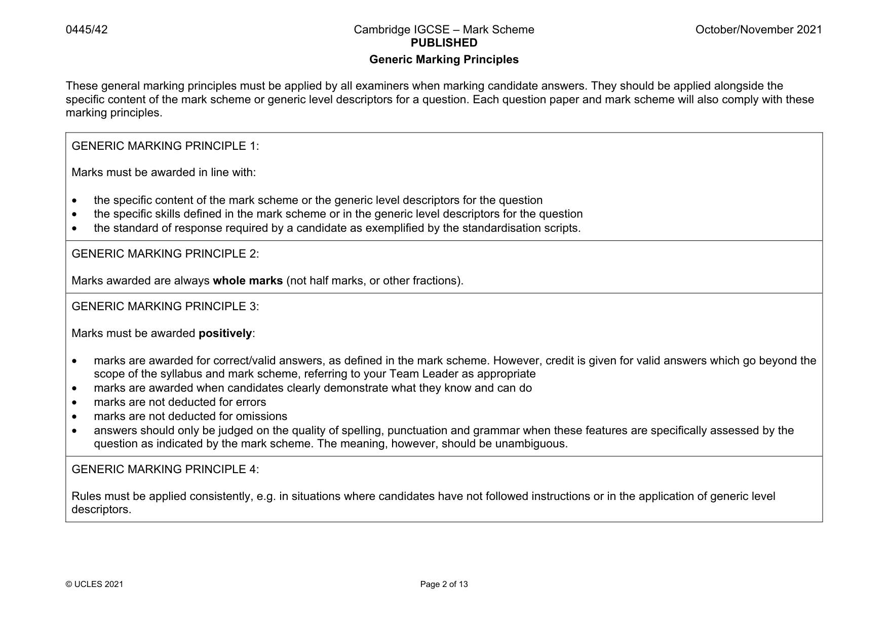
The question paper and its mark scheme, free to read here and free to download. This is Cambridge’s own paper, exactly as it was sat.
Question paper20 pages

Mark scheme13 pages
Answers below. Sit the paper first if you are practising.
Questions as text
Q1 · A satellite dish for a television
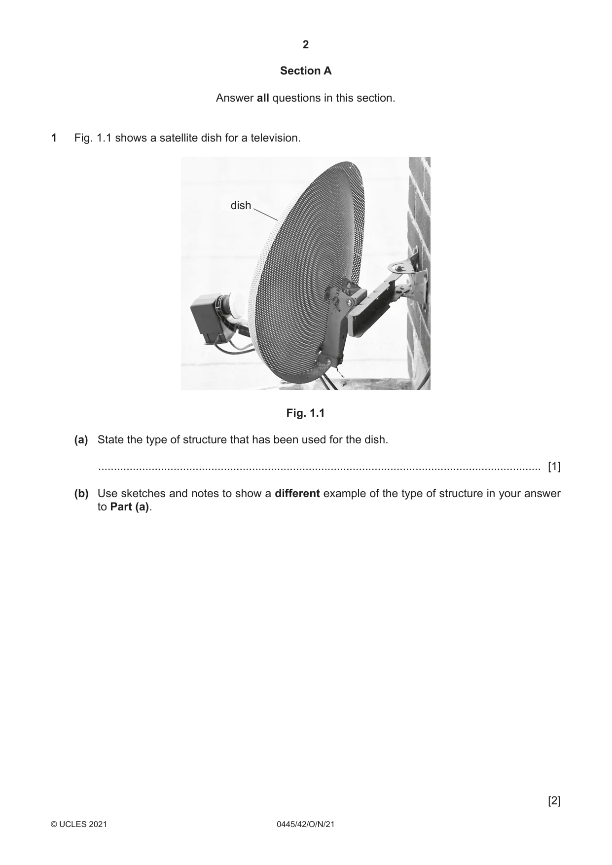
1 Fig. 1.1 shows a satellite dish for a television. dish Fig. 1.1 (a) State the type of structure that has been used for the dish. ............................................................................................................................................. [1] (b) Use sketches and notes to show a different example of the type of structure in your answer to Part (a). [2]
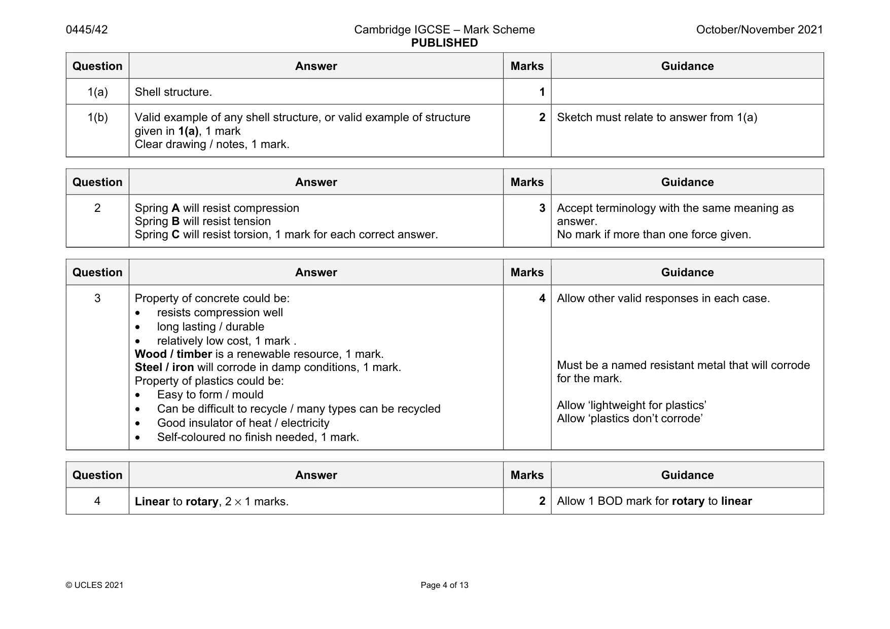
Mark scheme: 1(a) Shell structure. 1 1(b) Valid example of any shell structure, or valid example of structure given in 1(a), 1 mark Clear drawing / notes, 1 mark. 2 Sketch must relate to answer from 1(a)
Q2 · Three types of spring
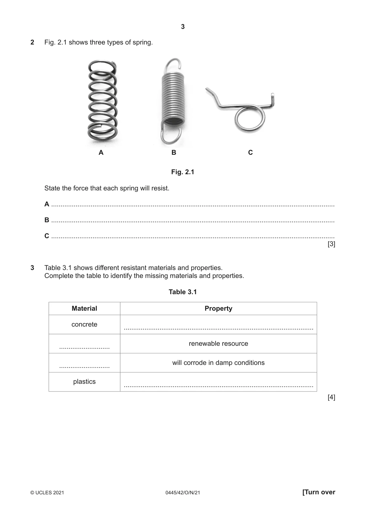
2 Fig. 2.1 shows three types of spring. A B C Fig. 2.1 State the force that each spring will resist. A ....................................................................................................................................................... B ....................................................................................................................................................... C ....................................................................................................................................................... [3]
Mark scheme: 2 Spring A will resist compression Spring B will resist tension Spring C will resist torsion, 1 mark for each correct answer. 3 Accept terminology with the same meaning as answer. No mark if more than one force given.
Q3 · Different resistant materials and properties
3 Table 3.1 shows different resistant materials and properties. Complete the table to identify the missing materials and properties. Table 3.1 Material Property concrete ..................................................................................................... renewable resource ........................... will corrode in damp conditions ........................... plastics ..................................................................................................... [4]
Mark scheme: 3 Property of concrete could be: • resists compression well • long lasting / durable • relatively low cost, 1 mark . Wood / timber is a renewable resource, 1 mark. Steel / iron will corrode in damp conditions, 1 mark. Property of plastics could be: • Easy to form / mould • Can be difficult to recycle / many types can be recycled • Good insulator of heat / electricity • Self-coloured no finish needed, 1 mark. 4 Allow other valid responses in each case. Must be a named resistant metal that will corrode for the mark. Allow ‘lightweight for plastics’ Allow ‘plastics don’t corrode’
Q4 · A parcel tape dispenser
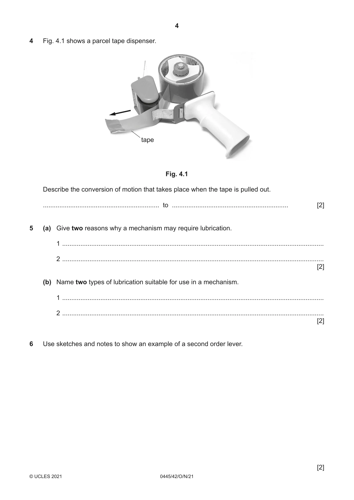
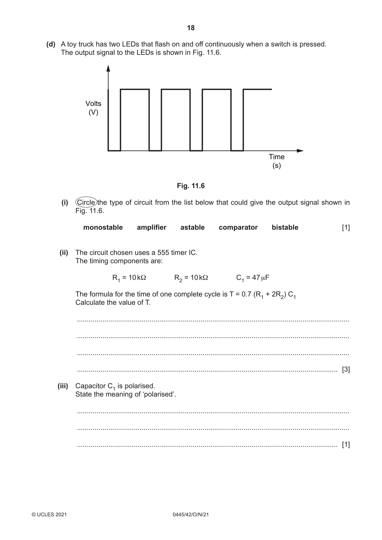
4 Fig. 4.1 shows a parcel tape dispenser. tape Fig. 4.1 Describe the conversion of motion that takes place when the tape is pulled out. ................................................................ to ................................................................ [2]
Mark scheme: 4 Linear to rotary, 2 × 1 marks. 2 Allow 1 BOD mark for rotary to linear
Q5 · Give two reasons why a mechanism may require lubrication
5 (a) Give two reasons why a mechanism may require lubrication. 1 ................................................................................................................................................ 2 ................................................................................................................................................ [2] (b) Name two types of lubrication suitable for use in a mechanism. 1 ................................................................................................................................................ 2 ................................................................................................................................................ [2]
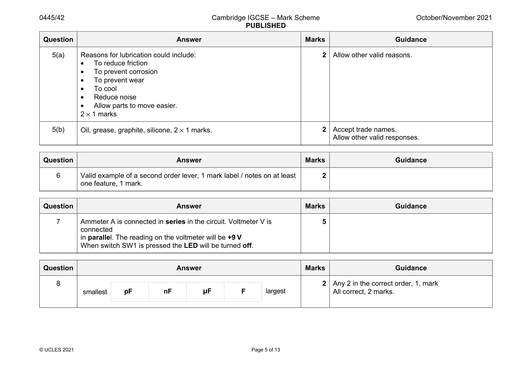
Mark scheme: 5(a) Reasons for lubrication could include: • To reduce friction • To prevent corrosion • To prevent wear • To cool • Reduce noise • Allow parts to move easier. 2 × 1 marks 2 Allow other valid reasons. 5(b) Oil, grease, graphite, silicone, 2 × 1 marks. 2 Accept trade names. Allow other valid responses.
Q6 · Use sketches and notes to show an example of a second order lever
6 Use sketches and notes to show an example of a second order lever. [2]
Mark scheme: 6 Valid example of a second order lever, 1 mark label / notes on at least one feature, 1 mark. 2
Question 7
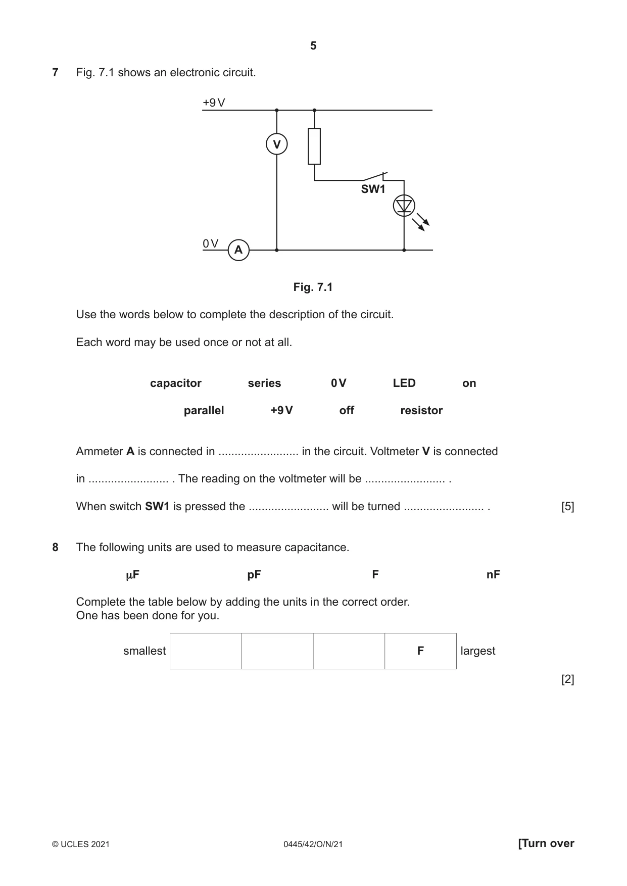
7 Fig. 7.1 shows an electronic circuit. +9 V V SW1 0 V A Fig. 7.1 Use the words below to complete the description of the circuit. Each word may be used once or not at all. capacitor series 0 V LED on parallel +9 V off resistor Ammeter A is connected in ......................... in the circuit. Voltmeter V is connected in ......................... . The reading on the voltmeter will be ......................... . When switch SW1 is pressed the ......................... will be turned ......................... . [5]
Mark scheme: 7 Ammeter A is connected in series in the circuit. Voltmeter V is connected in parallel. The reading on the voltmeter will be +9 V When switch SW1 is pressed the LED will be turned off. 5
Q8 · The following units are used to measure capacitance
8 The following units are used to measure capacitance. μF pF F nF Complete the table below by adding the units in the correct order. One has been done for you. smallest F largest [2]
Mark scheme: 8 2 Any 2 in the correct order, 1, mark All correct, 2 marks. smallest largest F µF pF nF
Q9 · Part of a plastic case to hold a circuit board
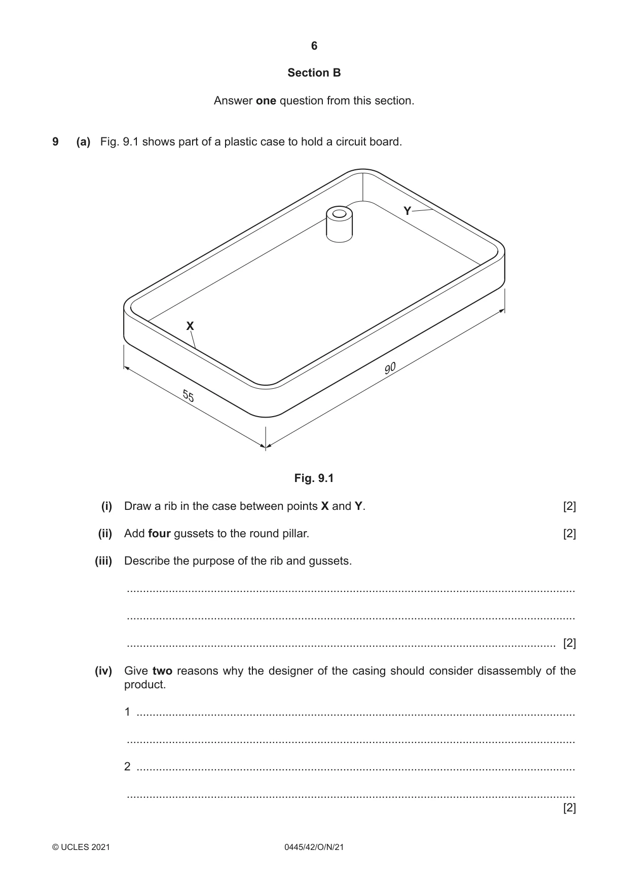
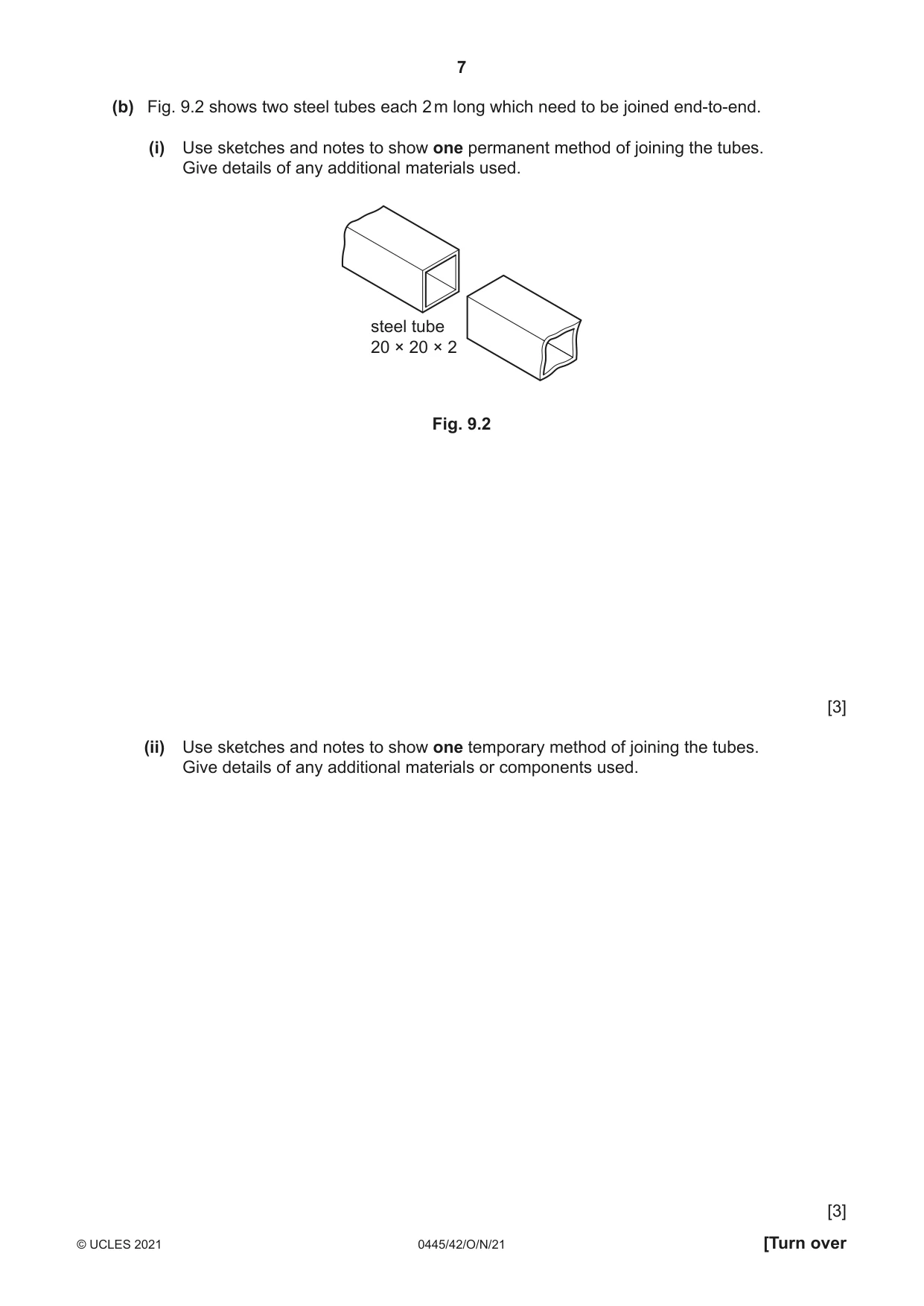
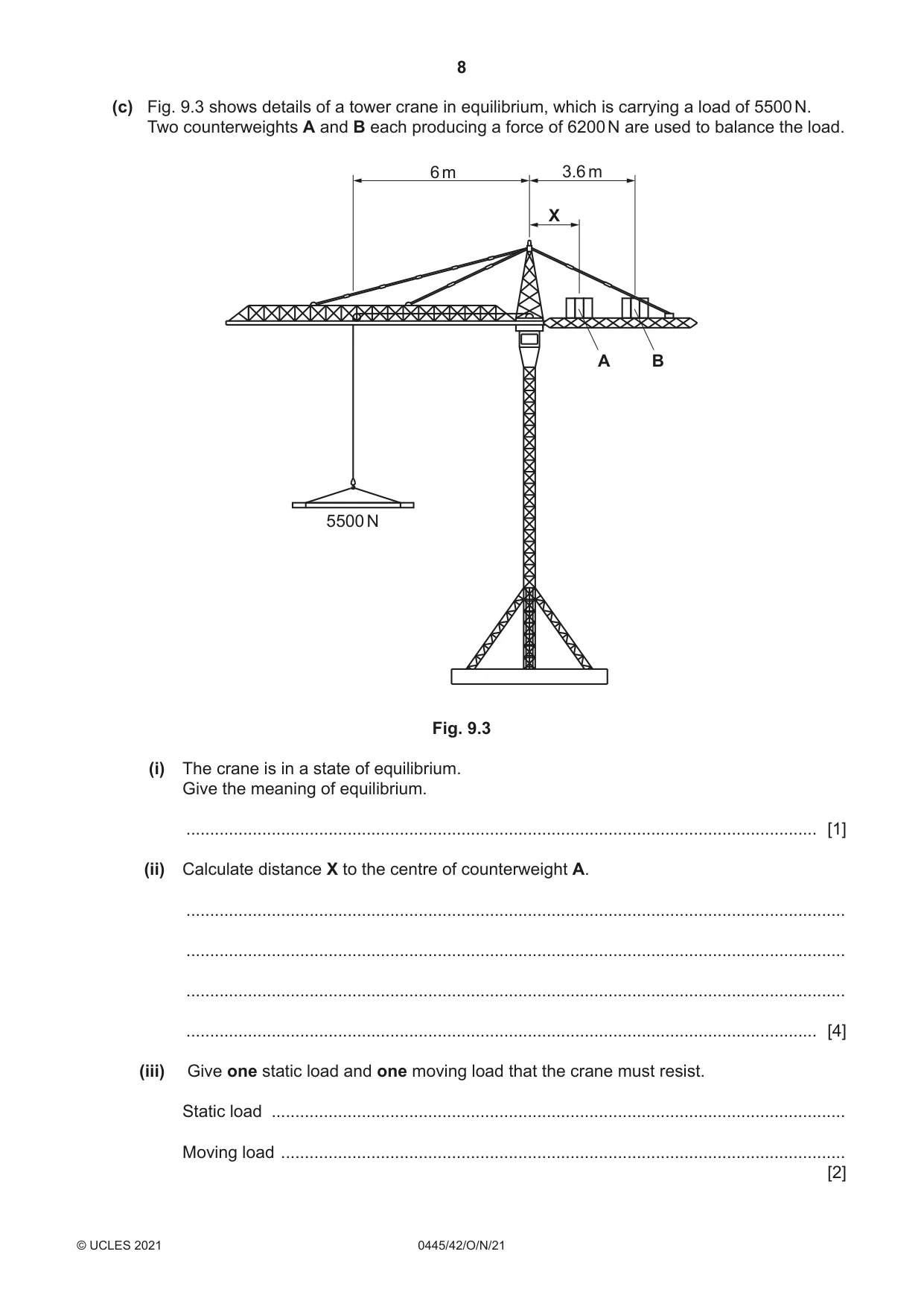
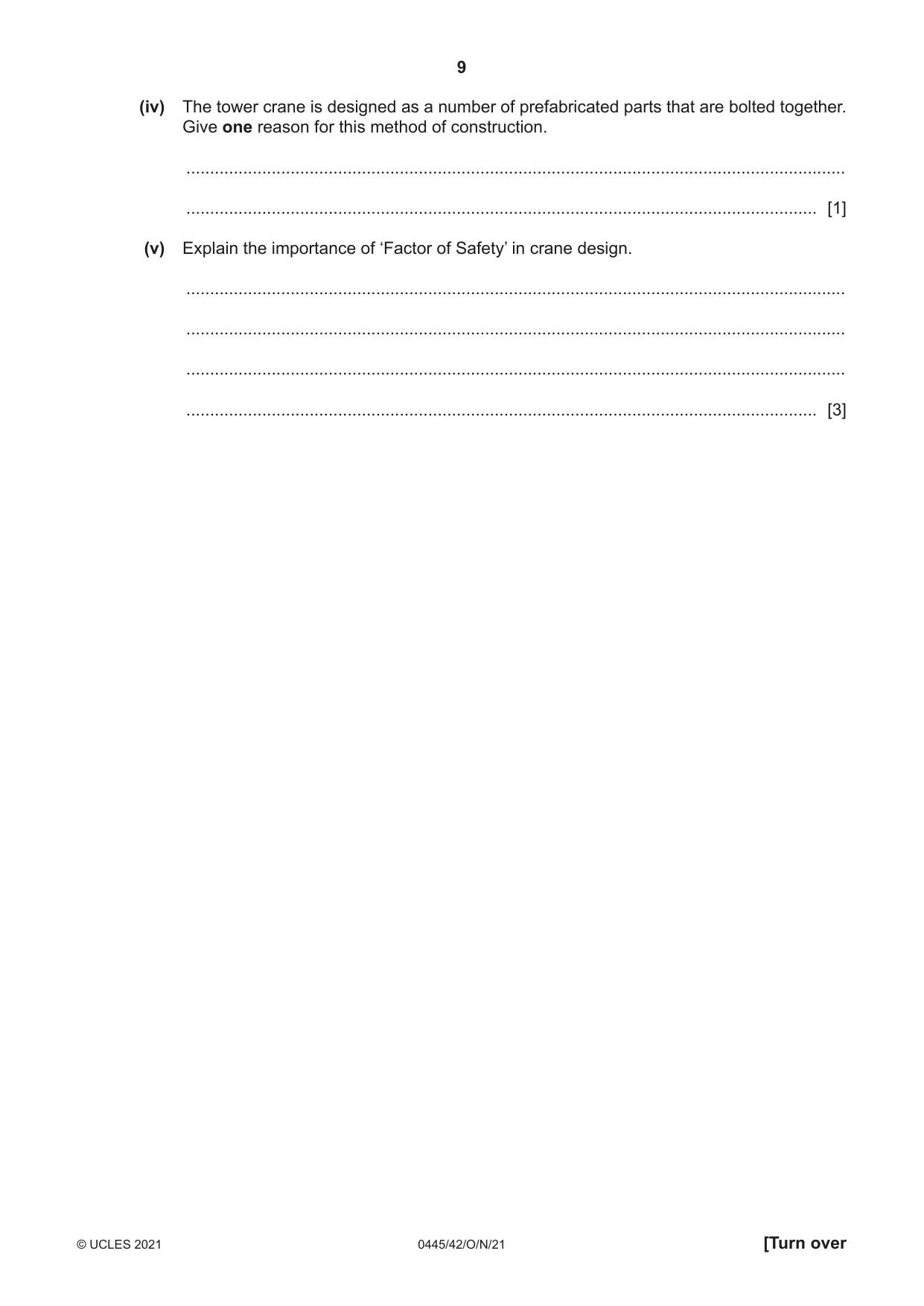
9 (a) Fig. 9.1 shows part of a plastic case to hold a circuit board. Y X 90 55 Fig. 9.1 (i) Draw a rib in the case between points X and Y. [2] (ii) Add four gussets to the round pillar. [2] (iii) Describe the purpose of the rib and gussets. ........................................................................................................................................... ........................................................................................................................................... ..................................................................................................................................... [2] (iv) Give two reasons why the designer of the casing should consider disassembly of the product. 1 ........................................................................................................................................ ........................................................................................................................................... 2 ........................................................................................................................................ ........................................................................................................................................... [2] (b) Fig. 9.2 shows two steel tubes each 2 m long which need to be joined end-to-end. (i) Use sketches and notes to show one permanent method of joining the tubes. Give details of any additional materials used. steel tube 20 × 20 × 2 Fig. 9.2 [3] (ii) Use sketches and notes to show one temporary method of joining the tubes. Give details of any additional materials or components used. [3] (c) Fig. 9.3 shows details of a tower crane in equilibrium, which is carrying a load of 5500 N. Two counterweights A and B each producing a force of 6200 N are used to balance the load. 6 m 3.6 m X A B 5500 N Fig. 9.3 (i) The crane is in a state of equilibrium. Give the meaning of equilibrium. ..................................................................................................................................... [1] (ii) Calculate distance X to the centre of counterweight A. ........................................................................................................................................... ........................................................................................................................................... ........................................................................................................................................... ..................................................................................................................................... [4] (iii) Give one static load and one moving load that the crane must resist. Static load ......................................................................................................................... Moving load ....................................................................................................................... [2] (iv) The tower crane is designed as a number of prefabricated parts that are bolted together. Give one reason for this method of construction. ........................................................................................................................................... ..................................................................................................................................... [1] (v) Explain the importance of ‘Factor of Safety’ in crane design. ........................................................................................................................................... ........................................................................................................................................... ........................................................................................................................................... ..................................................................................................................................... [3]
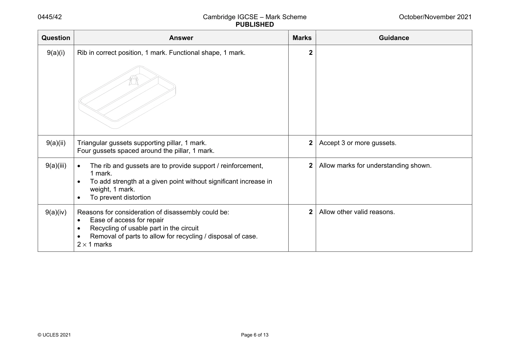
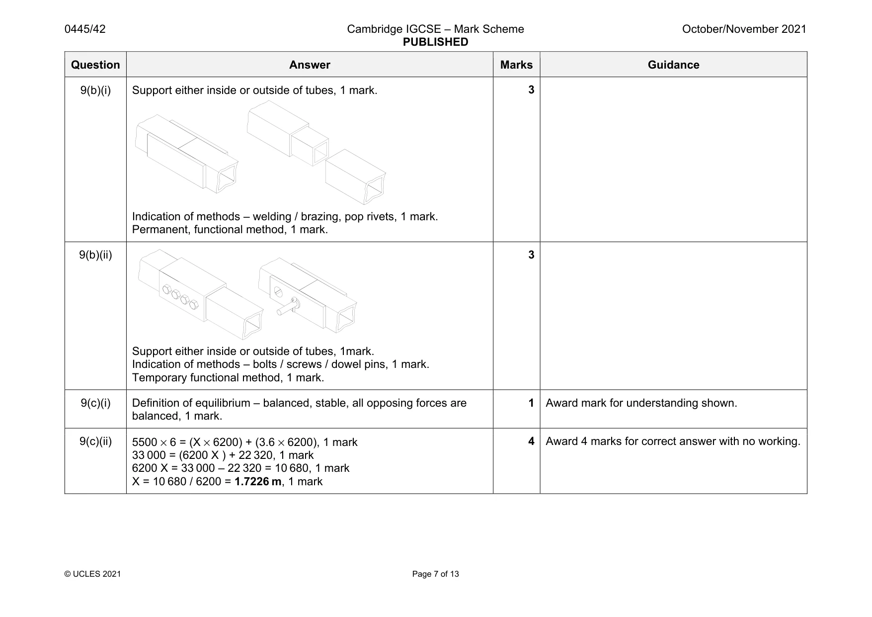
Mark scheme: 9(a)(i) Rib in correct position, 1 mark. Functional shape, 1 mark. 2 9(a)(ii) Triangular gussets supporting pillar, 1 mark. Four gussets spaced around the pillar, 1 mark. 2 Accept 3 or more gussets. 9(a)(iii) • The rib and gussets are to provide support / reinforcement, 1 mark. • To add strength at a given point without significant increase in weight, 1 mark. • To prevent distortion 2 Allow marks for understanding shown. 9(a)(iv) Reasons for consideration of disassembly could be: • Ease of access for repair • Recycling of usable part in the circuit • Removal of parts to allow for recycling / disposal of case. 2 × 1 marks 2 Allow other valid reasons. Question Answer Marks Guidance 9(b)(i) Support either inside or outside of tubes, 1 mark. Indication of methods – welding / brazing, pop rivets, 1 mark. Permanent, functional method, 1 mark. 3 9(b)(ii) Support either inside or outside of tubes, 1mark. Indication of methods – bolts / screws / dowel pins, 1 mark. Temporary functional method, 1 mark. 3 9(c)(i) Definition of equilibrium – balanced, stable, all opposing forces are balanced, 1 mark. 1 Award mark for understanding shown. 9(c)(ii) 5500 × 6 = (X × 6200) + (3.6 × 6200), 1 mark 33 000 = (6200 X ) + 22 320, 1 mark 6200 X = 33 000 – 22 320 = 10 680, 1 mark X = 10 680 / 6200 = 1.7226 m, 1 mark 4 Award 4 marks for correct answer with no working. Question Answer Marks Guidance 9(c)(iii) Static load is: • Load from any of the crane components • Counterweights Moving load is: • Wind, snow, any other weather related condition • Load from items being lifted • Torque caused by rotation of the tower • Movement / swinging of the load being lifted 2 × 1 marks 1 mark for each 2 9(c)(iv) Reason for prefabrication will include: • Can be constructed and then moved to site • Ease of storage • Ease of transport • Crane structure is temporary. 1 mark. 1 Do not allow cost related reason. Allow other valid reasons. 9(c)(v) Points in explanation could include: • Unknown loads and conditions of use • Designer must consider all who will be working on the crane or in the area • Unknown stability of foundations where the base will rest. • Compliance with safety legislation. 3 1 mark for each point mentioned. Allow 2 marks for a fully justified point.
Q10 · Details of a cam operated clamp that is locked in place by a lever
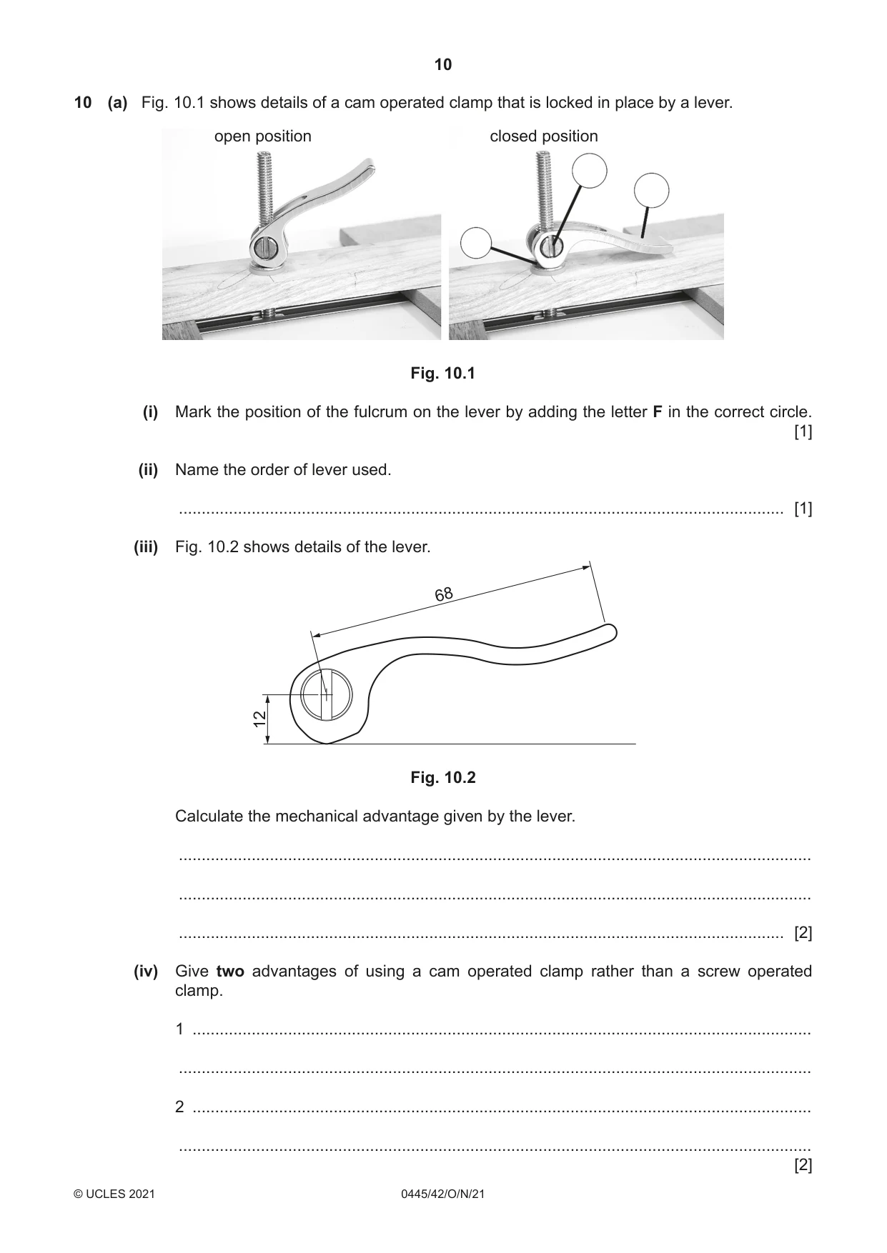
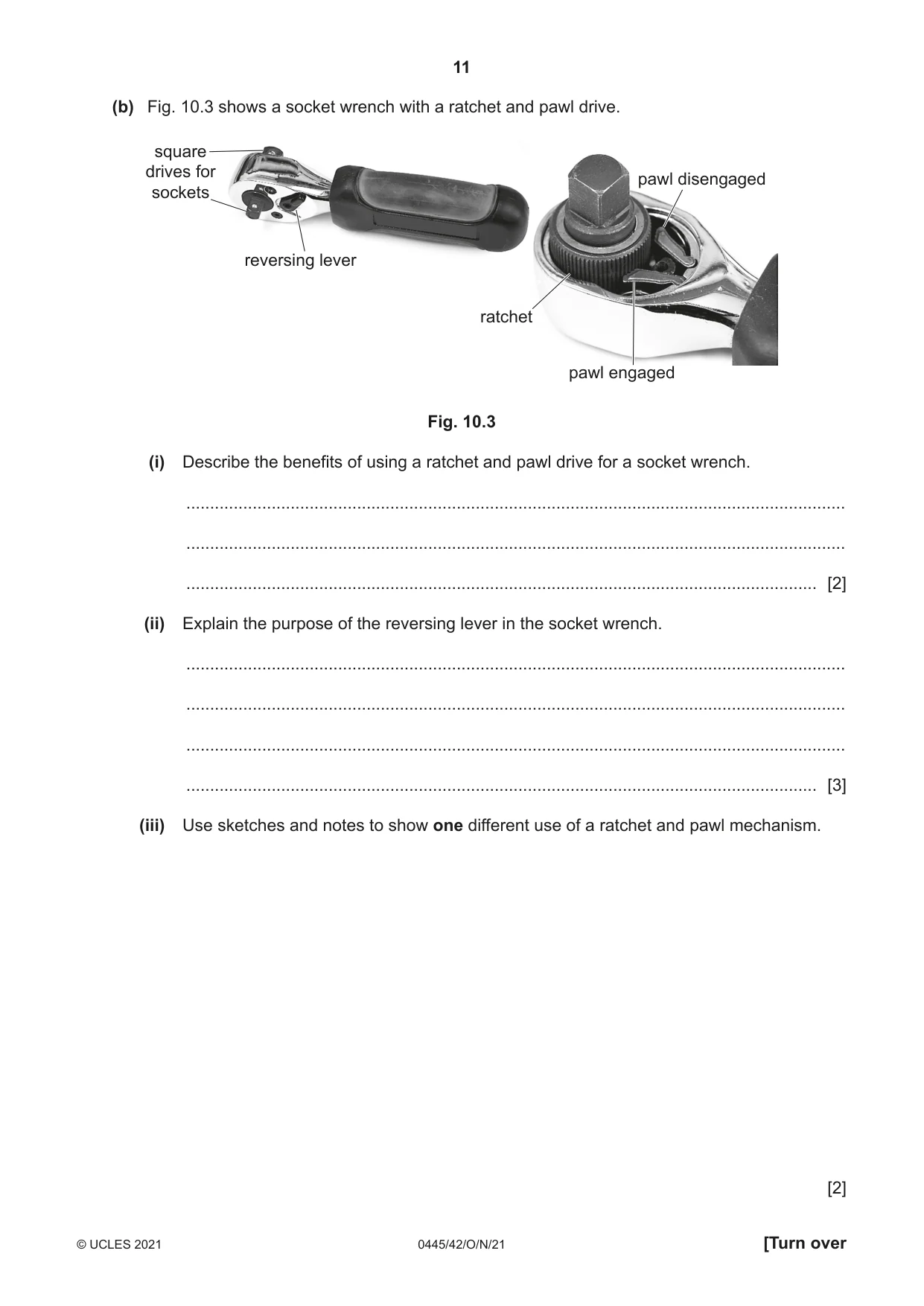
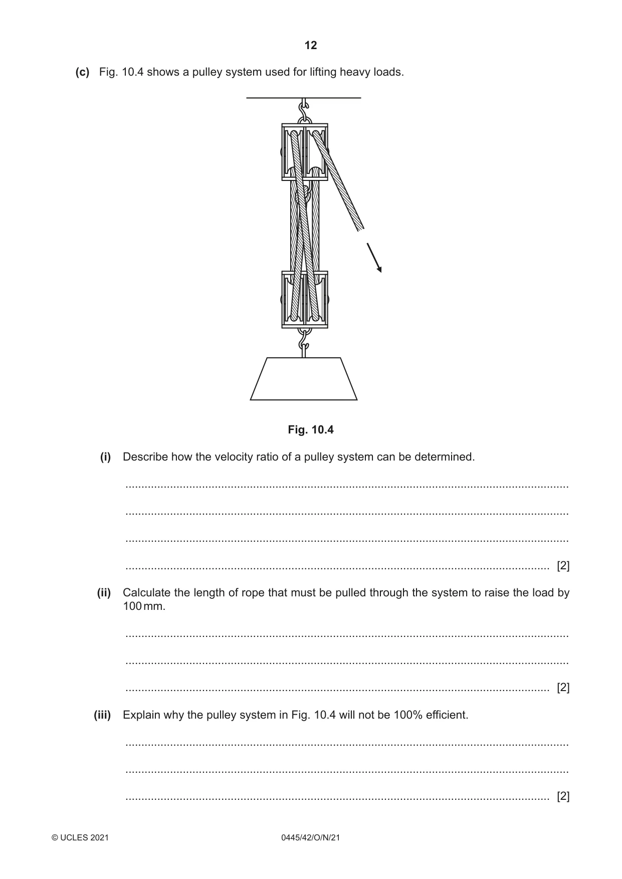
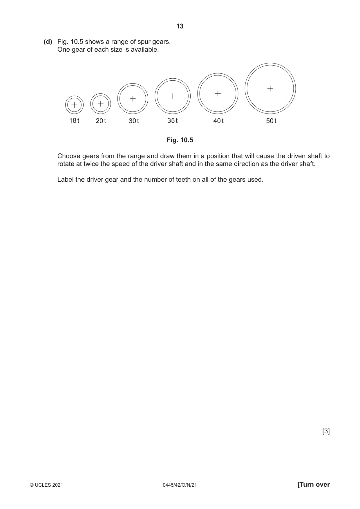
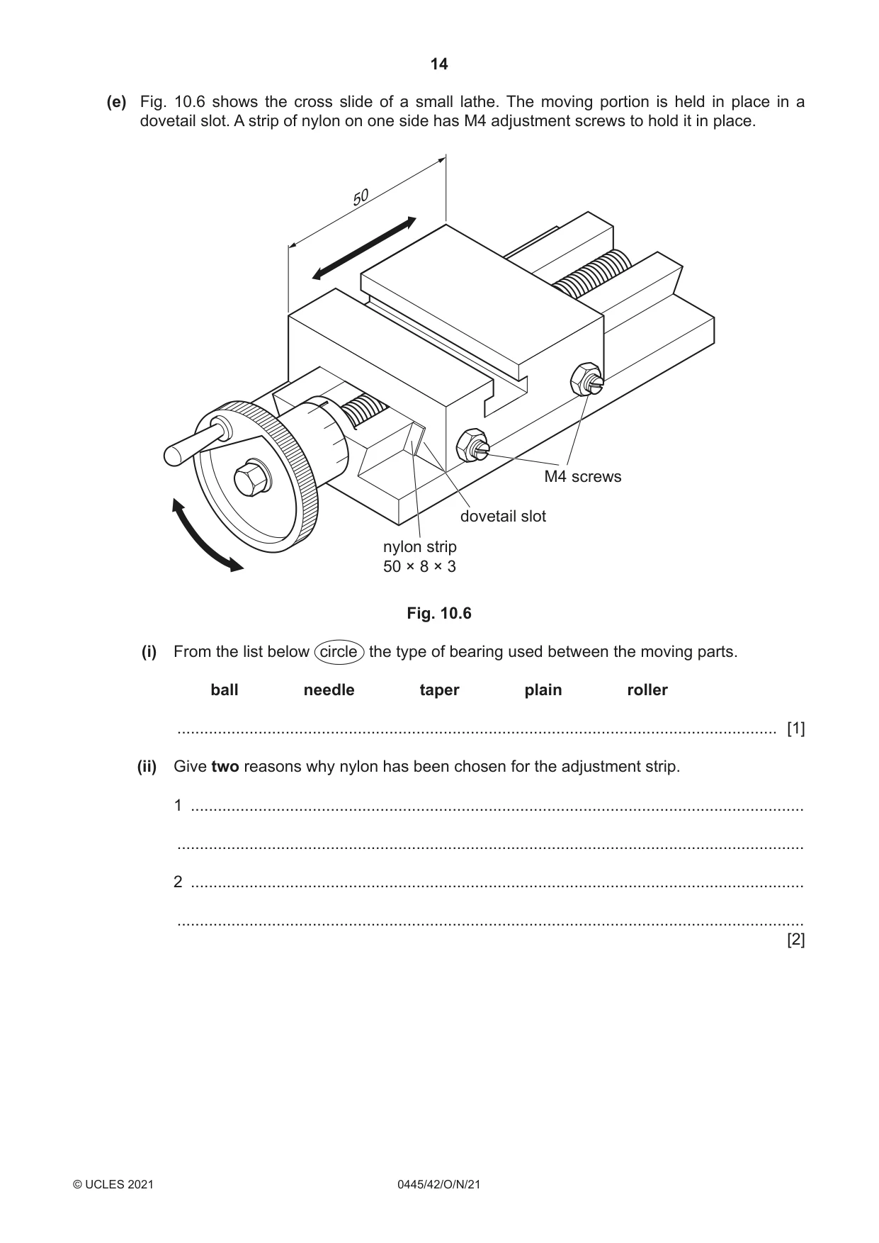
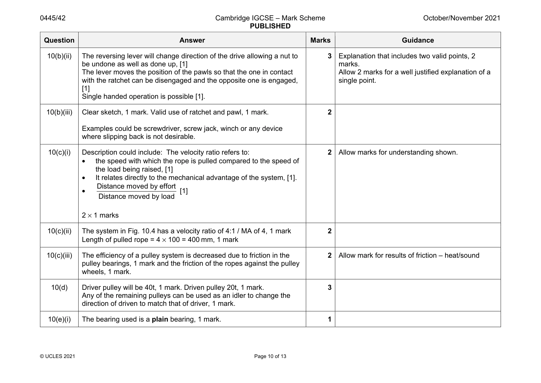
10 (a) Fig. 10.1 shows details of a cam operated clamp that is locked in place by a lever. open position closed position Fig. 10.1 (i) Mark the position of the fulcrum on the lever by adding the letter F in the correct circle. [1] (ii) Name the order of lever used. ..................................................................................................................................... [1] (iii) Fig. 10.2 shows details of the lever. 68 12 Fig. 10.2 Calculate the mechanical advantage given by the lever. ........................................................................................................................................... ........................................................................................................................................... ..................................................................................................................................... [2] (iv) Give two advantages of using a cam operated clamp rather than a screw operated clamp. 1 ........................................................................................................................................ ........................................................................................................................................... 2 ........................................................................................................................................ ........................................................................................................................................... [2] (b) Fig. 10.3 shows a socket wrench with a ratchet and pawl drive. square drives for pawl disengaged sockets reversing lever ratchet pawl engaged Fig. 10.3 (i) Describe the benefits of using a ratchet and pawl drive for a socket wrench. ........................................................................................................................................... ........................................................................................................................................... ..................................................................................................................................... [2] (ii) Explain the purpose of the reversing lever in the socket wrench. ........................................................................................................................................... ........................................................................................................................................... ........................................................................................................................................... ..................................................................................................................................... [3] (iii) Use sketches and notes to show one different use of a ratchet and pawl mechanism. [2] (c) Fig. 10.4 shows a pulley system used for lifting heavy loads. Fig. 10.4 (i) Describe how the velocity ratio of a pulley system can be determined. ........................................................................................................................................... ........................................................................................................................................... ........................................................................................................................................... ..................................................................................................................................... [2] (ii) Calculate the length of rope that must be pulled through the system to raise the load by 100 mm. ........................................................................................................................................... ........................................................................................................................................... ..................................................................................................................................... [2] (iii) Explain why the pulley system in Fig. 10.4 will not be 100% efficient. ........................................................................................................................................... ........................................................................................................................................... ..................................................................................................................................... [2] (d) Fig. 10.5 shows a range of spur gears. One gear of each size is available. 18 t 20 t 30 t 35 t 40 t 50 t Fig. 10.5 Choose gears from the range and draw them in a position that will cause the driven shaft to rotate at twice the speed of the driver shaft and in the same direction as the driver shaft. Label the driver gear and the number of teeth on all of the gears used. [3] (e) Fig. 10.6 shows the cross slide of a small lathe. The moving portion is held in place in a dovetail slot. A strip of nylon on one side has M4 adjustment screws to hold it in place. 50 M4 screws dovetail slot nylon strip 50 × 8 × 3 Fig. 10.6 (i) From the list below circle the type of bearing used between the moving parts. ball needle taper plain roller ..................................................................................................................................... [1] (ii) Give two reasons why nylon has been chosen for the adjustment strip. 1 ........................................................................................................................................ ........................................................................................................................................... 2 ........................................................................................................................................ ........................................................................................................................................... [2]
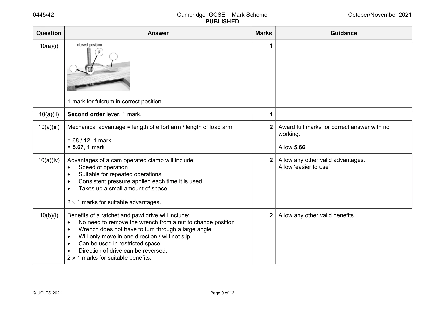
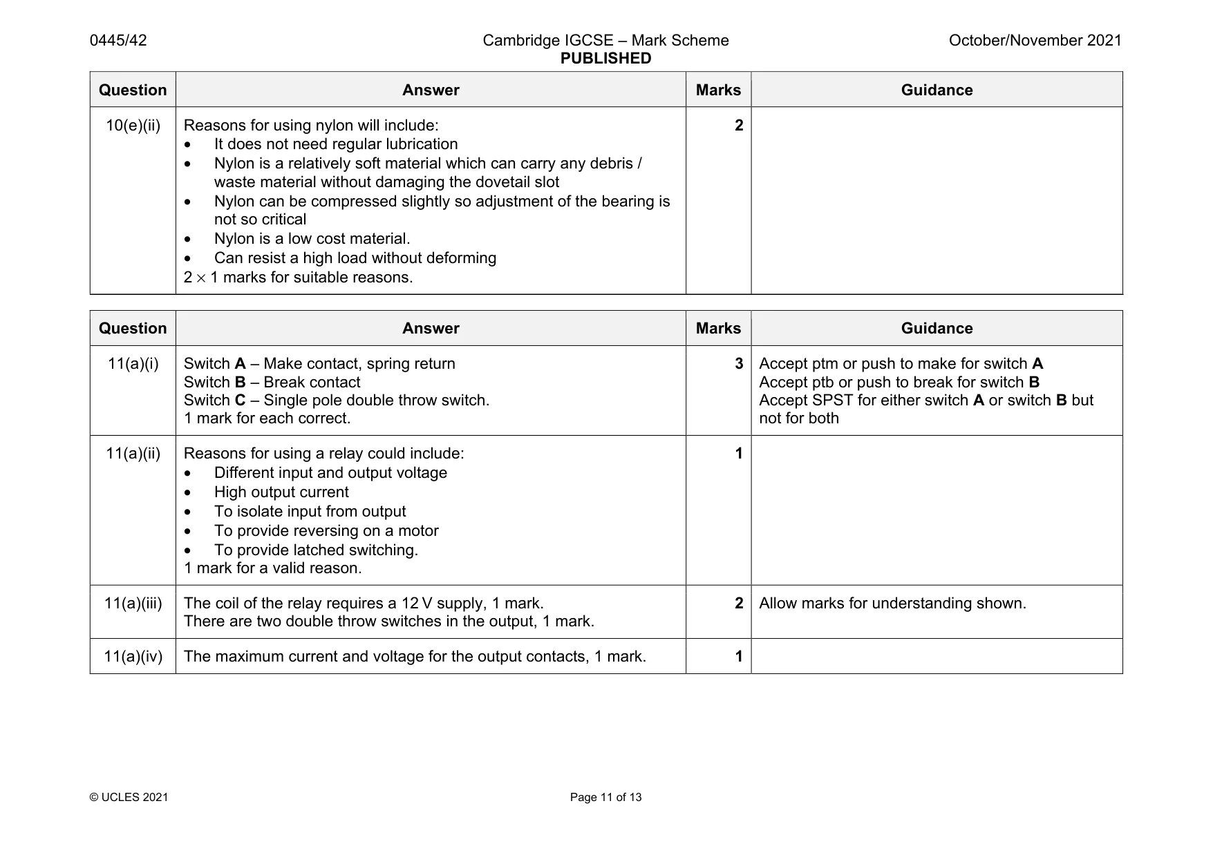
Mark scheme: 10(a)(i) 1 mark for fulcrum in correct position. 10(a)(ii) Second order lever, 1 mark. 1 10(a)(iii) Mechanical advantage = length of effort arm / length of load arm = 68 / 12, 1 mark = 5.67, 1 mark 2 Award full marks for correct answer with no working. Allow 5.66 10(a)(iv) Advantages of a cam operated clamp will include: • Speed of operation • Suitable for repeated operations • Consistent pressure applied each time it is used • Takes up a small amount of space. 2 × 1 marks for suitable advantages. 2 Allow any other valid advantages. Allow ‘easier to use’ 10(b)(i) Benefits of a ratchet and pawl drive will include: • No need to remove the wrench from a nut to change position • Wrench does not have to turn through a large angle • Will only move in one direction / will not slip • Can be used in restricted space • Direction of drive can be reversed. 2 × 1 marks for suitable benefits. 2 Allow any other valid benefits. Question Answer Marks Guidance 10(b)(ii) The reversing lever will change direction of the drive allowing a nut to be undone as well as done up, [1] The lever moves the position of the pawls so that the one in contact with the ratchet can be disengaged and the opposite one is engaged, [1] Single handed operation is possible [1]. 3 Explanation that includes two valid points, 2 marks. Allow 2 marks for a well justified explanation of a single point. 10(b)(iii) Clear sketch, 1 mark. Valid use of ratchet and pawl, 1 mark. Examples could be screwdriver, screw jack, winch or any device where slipping back is not desirable. 2 10(c)(i) Description could include: The velocity ratio refers to: • the speed with which the rope is pulled compared to the speed of the load being raised, [1] • It relates directly to the mechanical advantage of the system, [1]. • Distance moved by effort Distance moved by load [1] 2 × 1 marks 2 Allow marks for understanding shown. 10(c)(ii) The system in Fig. 10.4 has a velocity ratio of 4:1 / MA of 4, 1 mark Length of pulled rope = 4 × 100 = 400 mm, 1 mark 2 10(c)(iii) The efficiency of a pulley system is decreased due to friction in the pulley bearings, 1 mark and the friction of the ropes against the pulley wheels, 1 mark. 2 Allow mark for results of friction – heat/sound 10(d) Driver pulley will be 40t, 1 mark. Driven pulley 20t, 1 mark. Any of the remaining pulleys can be used as an idler to change the direction of driven to match that of driver, 1 mark. 3 10(e)(i) The bearing used is a plain bearing, 1 mark. 1 Question Answer Marks Guidance 10(e)(ii) Reasons for using nylon will include: • It does not need regular lubrication • Nylon is a relatively soft material which can carry any debris / waste material without damaging the dovetail slot • Nylon can be compressed slightly so adjustment of the bearing is not so critical • Nylon is a low cost material. • Can resist a high load without deforming 2 × 1 marks for suitable reasons. 2
Question 11
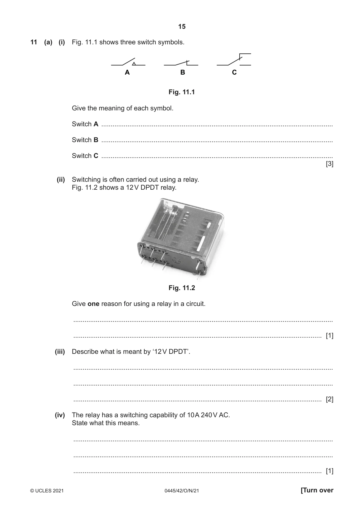
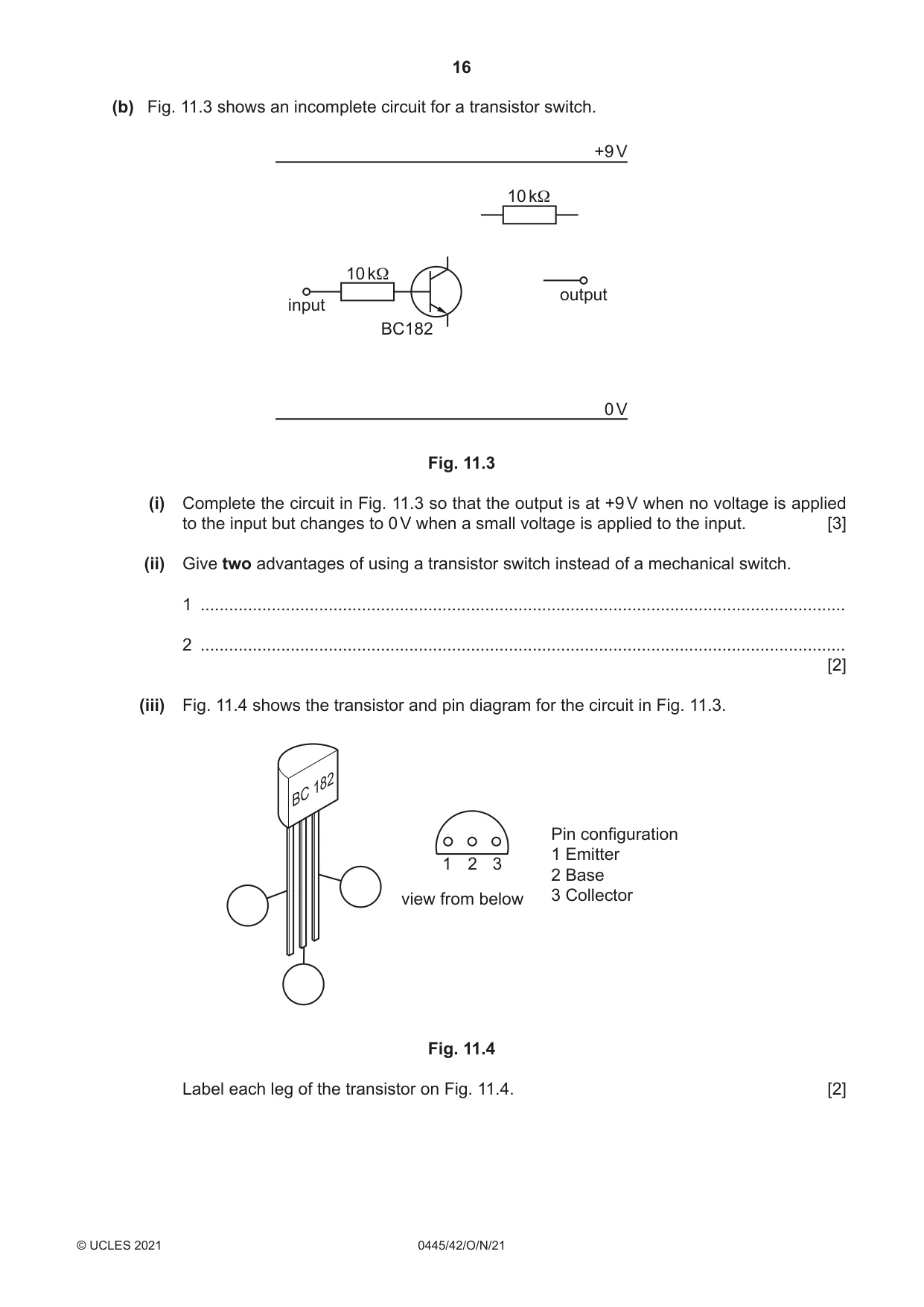
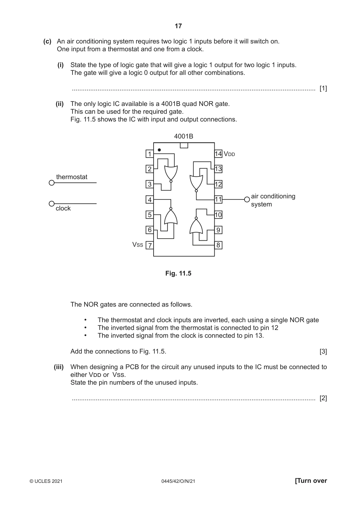
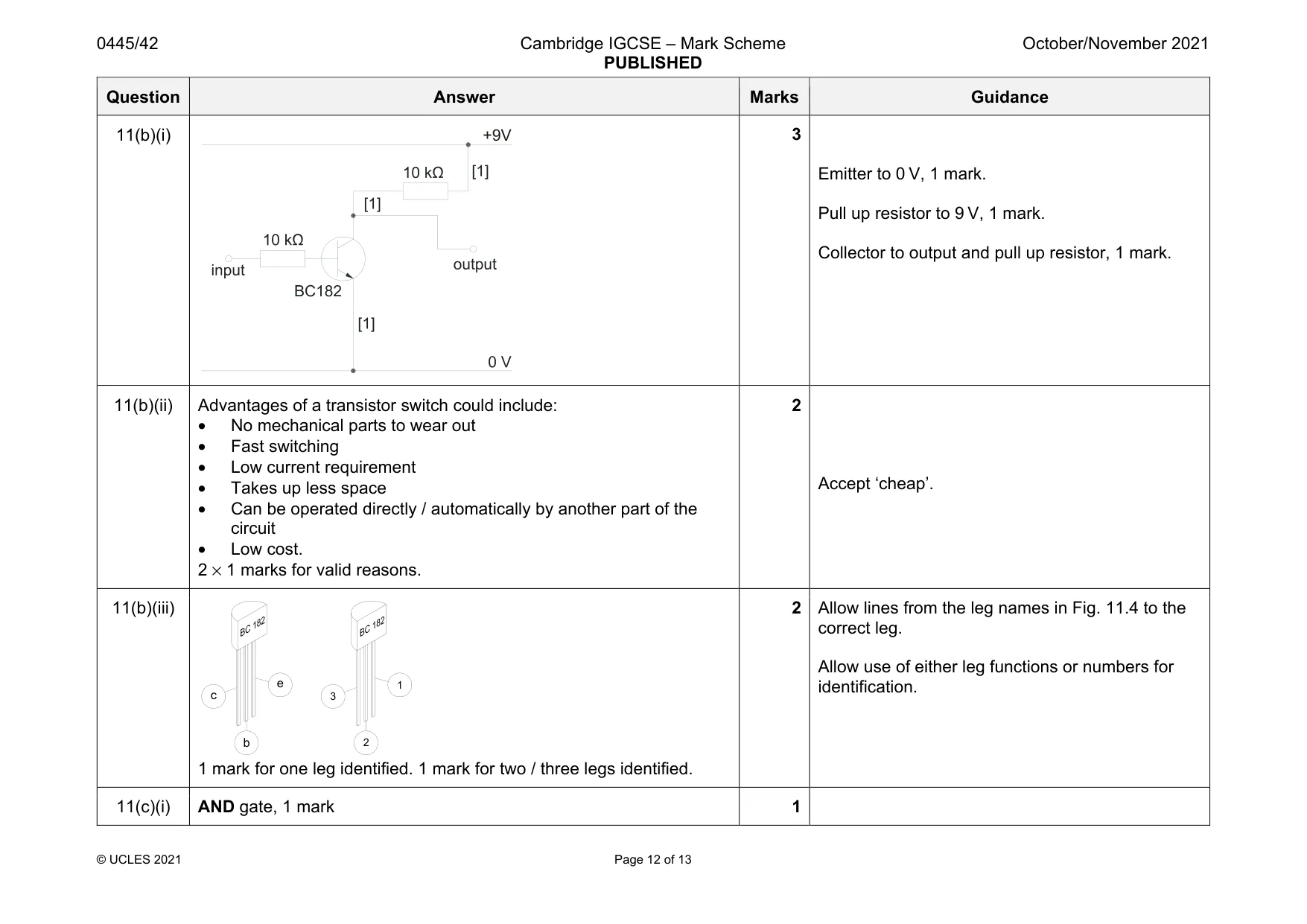
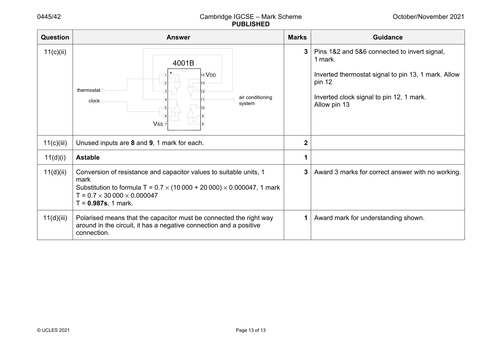
11 (a) (i) Fig. 11.1 shows three switch symbols. A B C Fig. 11.1 Give the meaning of each symbol. Switch A ............................................................................................................................ Switch B ............................................................................................................................ Switch C ............................................................................................................................ [3] (ii) Switching is often carried out using a relay. Fig. 11.2 shows a 12 V DPDT relay. Fig. 11.2 Give one reason for using a relay in a circuit. ........................................................................................................................................... ..................................................................................................................................... [1] (iii) Describe what is meant by ‘12 V DPDT’. ........................................................................................................................................... ........................................................................................................................................... ..................................................................................................................................... [2] (iv) The relay has a switching capability of 10 A 240 V AC. State what this means. ........................................................................................................................................... ........................................................................................................................................... ..................................................................................................................................... [1] (b) Fig. 11.3 shows an incomplete circuit for a transistor switch. +9 V 10 kΩ 10 kΩ output input BC182 0 V Fig. 11.3 (i) Complete the circuit in Fig. 11.3 so that the output is at +9 V when no voltage is applied to the input but changes to 0 V when a small voltage is applied to the input. [3] (ii) Give two advantages of using a transistor switch instead of a mechanical switch. 1 ........................................................................................................................................ 2 ........................................................................................................................................ [2] (iii) Fig. 11.4 shows the transistor and pin diagram for the circuit in Fig. 11.3. 182 BC Pin configuration 1 Emitter 1 2 3 2 Base view from below 3 Collector Fig. 11.4 Label each leg of the transistor on Fig. 11.4. [2] (c) An air conditioning system requires two logic 1 inputs before it will switch on. One input from a thermostat and one from a clock. (i) State the type of logic gate that will give a logic 1 output for two logic 1 inputs. The gate will give a logic 0 output for all other combinations. ..................................................................................................................................... [1] (ii) The only logic IC available is a 4001B quad NOR gate. This can be used for the required gate. Fig. 11.5 shows the IC with input and output connections. 4001B 1 14 VDD 2 13 thermostat 3 12 air conditioning 4 11 system clock 5 10 6 9 VSS 7 8 Fig. 11.5 The NOR gates are connected as follows. • The thermostat and clock inputs are inverted, each using a single NOR gate • The inverted signal from the thermostat is connected to pin 12 • The inverted signal from the clock is connected to pin 13. Add the connections to Fig. 11.5. [3] (iii) When designing a PCB for the circuit any unused inputs to the IC must be connected to either Vdd or Vss. State the pin numbers of the unused inputs. ..................................................................................................................................... [2]
Mark scheme: 11(a)(i) Switch A – Make contact, spring return Switch B – Break contact Switch C – Single pole double throw switch. 1 mark for each correct. Accept ptb or push to break for switch B Accept SPST for either switch A or switch B but not for both 11(a)(ii) Reasons for using a relay could include: • Different input and output voltage • High output current • To isolate input from output • To provide reversing on a motor • To provide latched switching. 1 mark for a valid reason. 1 11(a)(iii) The coil of the relay requires a 12 V supply, 1 mark. There are two double throw switches in the output, 1 mark. 2 Allow marks for understanding shown. 11(a)(iv) The maximum current and voltage for the output contacts, 1 mark. 1 Question Answer Marks Guidance 11(b)(i) 3 Emitter to 0 V, 1 mark. Pull up resistor to 9 V, 1 mark. Collector to output and pull up resistor, 1 mark. 11(b)(ii) Advantages of a transistor switch could include: • No mechanical parts to wear out • Fast switching • Low current requirement • Takes up less space • Can be operated directly / automatically by another part of the circuit • Low cost. 2 × 1 marks for valid reasons. 2 Accept ‘cheap’. 11(b)(iii) 1 mark for one leg identified. 1 mark for two / three legs identified. 2 Allow lines from the leg names in Fig. 11.4 to the correct leg. Allow use of either leg functions or numbers for identification. 11(c)(i) AND gate, 1 mark 1 +9V e b c 1 2 3 Question Answer Marks Guidance 11(c)(ii) 3 Pins 1&2 and 5&6 connected to invert signal, 1 mark. Inverted thermostat signal to pin 13, 1 mark. Allow pin 12 Inverted clock signal to pin 12, 1 mark. Allow pin 13 11(c)(iii) Unused inputs are 8 and 9, 1 mark for each. 2 11(d)(i) Astable 1 11(d)(ii) Conversion of resistance and capacitor values to suitable units, 1 mark Substitution to formula T = 0.7 × (10 000 + 20 000) × 0.000047, 1 mark T = 0.7 × 30 000 × 0.000047 T = 0.987s, 1 mark. 3 Award 3 marks for correct answer with no working. 11(d)(iii) Polarised means that the capacitor must be connected the right way around in the circuit, it has a negative connection and a positive connection. 1 Award mark for understanding shown. thermostat clock air conditioning system
What was in this paper
The subtopics covered by these 11 questions, and how many questions each got. Open one in a new tab to see every Cambridge question on it.
What you needed in this session
Cambridge’s own grade thresholds for 2021 Oct/Nov, Paper 4 · Variant 2. A higher threshold means an easier paper — the bar moves with how the cohort did.